富士氧化锆氧分析仪使用说明书
氧化锆中文说明书
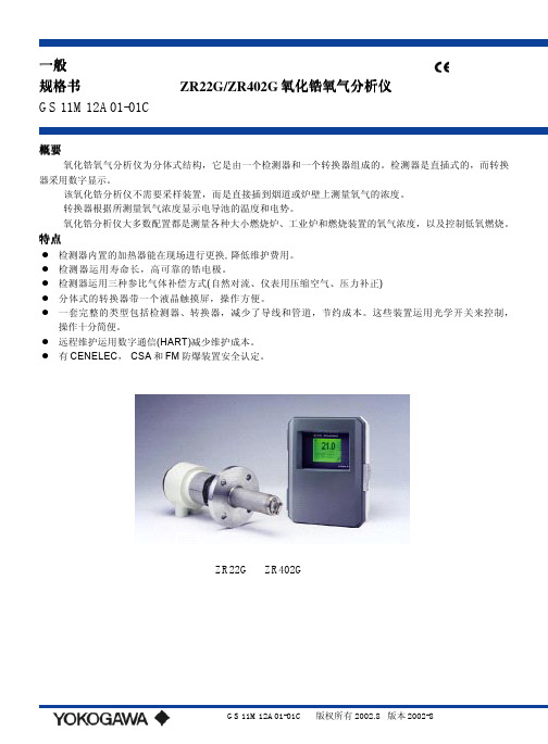
一般规格书ZR22G/ZR402G氧化锆氧气分析仪GS 11M12A01-01C概要氧化锆氧气分析仪为分体式结构,它是由一个检测器和一个转换器组成的。
检测器是直插式的,而转换器采用数字显示。
该氧化锆分析仪不需要采样装置,而是直接插到烟道或炉壁上测量氧气的浓度。
转换器根据所测量氧气浓度显示电导池的温度和电势。
氧化锆分析仪大多数配置都是测量各种大小燃烧炉、工业炉和燃烧装置的氧气浓度,以及控制低氧燃烧。
特点z检测器内置的加热器能在现场进行更换, 降低维护费用。
z检测器运用寿命长,高可靠的锆电极。
z检测器运用三种参比气体补偿方式(自然对流、仪表用压缩空气、压力补正)z分体式的转换器带一个液晶触摸屏,操作方便。
z一套完整的类型包括检测器、转换器,减少了导线和管道,节约成本。
这些装置运用光学开关来控制,操作十分简便。
z远程维护运用数字通信(HART)减少维护成本。
z有CENELEC, CSA和FM防爆装置安全认定。
ZR22G ZR402G芯屏蔽电缆加热器芯屏蔽电缆接点输出HART0~1400常用检测器应用SUS310S 800室。
700~1400℃(带高温探头适配器) 对高温采样气体,应用0.15m长的探头和高温探头适配器ZO21P-H。
采样气体压力:-5~+250kPa(当炉内压力超过3kPa,它用来压力补正; 当炉内压力超过5kPa,必须补偿压力)。
对0.15 m探头来说为0.5~5kPa。
在炉内不能有压力浮动。
探头长度: 0.15,0.4,0.7,1.0,1.5,2.0, 3.0,3.6,4.2,4.8,5.4m探头材料: SUS 316(JIS)环境温度:-20~+150 ℃涉及气体方式:自然对流,仪表用压缩空气,压力补正(其余的探头超过0.15m)仪表用压缩空气方式(包括自然对流除外):压力; 200 kPa+炉内压力(要求用通过露点-20℃以下的冷却干燥空气,且要没有灰尘和油垢。
)消耗量:大约1NL/min气体连接材料:SUS 316(JIS),氧化锆,SUS304(JIS)(法兰), 镍基合金B(Inconel 600,601)结构:加热器和热电偶可更换结构;非防爆产品;相当于国际电气制造业协会 4X/IP 66(只适用于经压力补正的熔炉进行再循环)端子盒材料:铝合金端子盒颜色:外壳:白色(Munsell 0.6GY3.1/2.0)盖子:墨绿(Munsell 2.5GY8.4/1.2)底部:聚亚安酯防腐材料气体连接:Rc1/4或1/4FNPT配线连接:G1/2,Pg13.5,M20×1.5mm,1/2NPT安装:法兰安装探头安装角度:当探头插入长度为2m以下时,安装角度可能为水平到垂直;当探头插入长度为2.5m以内时,安装角度可能为垂直(±5o),如果安装为水平到垂直,要一个保护套管:当探头插入长度为2.5m以上时,为垂直安装(±5o),要一个保护套管。
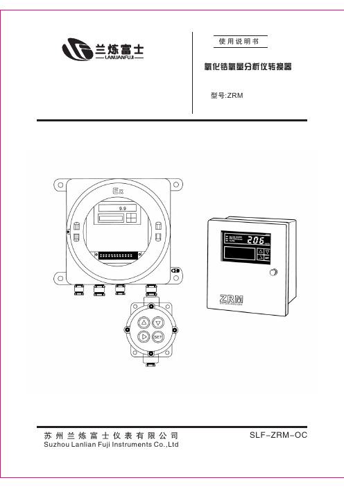
氧化锆氧量分析仪转换器说明书(ZRM)
6.5
(%) 0.01 0.1 0.5 1.0 1.5 2.0
(mV) 168.15 117.41 81.94 66.67 57.73 51.39
750~850℃( 700~800℃)
(
7
,
)
(
2
)
(
2
)
1.2V
(%) 5.0 10.0 15.0 20.0 20.6 21.0
(mV) 31.20 15.93 6.991 0.651 0 -0.4238
FAULT
NO
△
EXIT MEAS MODE
△
“HOLD” R
,
( )
(
),
: ,
”。
, 10 “
“R I C H M O D E” ,
2 0 0 m V( LED
0 . 0 0 2 3 % O 2) , 。
17
6.4
(
),
:
ALARM 1234s High alarm
( “ALARM” )
。
ALARM 1234s
9
10
( 2)
11
12
( 3)
22
23
24
23
250V AC 2A( ( 4)
18 19
20
: )
SELV
Primary
1 2 3 4 5 6 7 8 9 10 11 12 13 14
+
-+
-+
-+
-
( 1)
( 2)
15 16 17 18 19 20 21 22 23 24 25 26 27 28
D A D B FG DI1 DI2 COM
氧化锆分析仪和高温湿度分析仪 ZR22G、ZR402G、ZR202G 型 技术说明书

路中的现场装置的数量(多点模式)。 注:HART 是 HART Communication Fundation
的注册商标。 显示范围:0~100 vol %O2 加热时间:大约 20 分钟
重复性:(包括参比气是自然对流方式的情况) 范围设置最大值的 ±0.5%(不大于 0~25 vol %O2 范围 ) 范围设置最大值的 ±1%(大于 0~25 vol %O2 达到 0~100 vol %O2 范围 )
插入深度为 2.0m 时:大约 12kg(JIS 5K-65)/ 大约 17kg(ANSI 150-4)
插入深度为 3.0m 时:大约 15kg(JIS 5K-65)/ 大约 20kg(ANSI 150-4)
插入深度为 3.6m 时:大约 17kg(JIS 5K-65)/ 大约 22kg(ANSI 150-4)
2
3
系统的基本配置
系统配置—— 分离式
分离式分析仪的系统配置例 2
●参比气采用仪表气。为使校正更精确,应使用 标准气瓶作为校正气。
●应用:大型锅炉和加热炉等的氧浓度进行监测 和控制。在干燥炉和湿度调节器中对湿度进行 监测和控制。
系统配置—— 一体式 一体式分析仪的系统配置例 2
●参比气采用仪表气。为使校正更精确,应使用 标准气瓶作为校正气。
导线连接:G1/2,Pg13.5,M20 1.5mm,1/2NPT 任选 一型
304(JIS)(法兰),哈司特镍合金 B, (lnconel 600,601) 结构:加热器和热电偶可更换结构。非防爆产品。 相当于 NEMA 4X/IP66(仅仅适用于经过压 力补偿的炉内进行再循环)。 终端连接盒体:材料:铝合金 终端连接盒颜色: 盒体:白色(蒙赛尔色度 0.6GY3.1/2.0) 面板:海苔绿(蒙赛尔色度 2.5Y8.4/1.2) 外壳涂层:Polyurethane(聚亚安酯)防腐涂料 与气体的连接:Rc1/4 或 1/4FNPT 导线连接:G1/2, Pg13.5, M20 1.5mm, 1/2 NPT 安装:法兰安装 探头安装角度: 当探头的插入深度小于 2m 时,安装角度 的范围是从水平到垂直向下。当探头的 插入深度为 2.5m 或更长一些时,安装角 度垂直向下(±5°以内),若安装角度 的范围是从水平到垂直向下(±5°以 内),要使用探头保护器。当探头的插入 深度超过 2.5m 时,应垂直向下安装(±5° 以内),并要使用探头保护器。 重量:
氧化锆氧量分析仪维护和使用
氧化锆氧量分析仪维护和使用1、连接加热控制采样检测式氧探头,只有在氧传感器连接了加热控制以后才能正常工作,冷态下输出的是随机信号,不代表任何意义,氧传感器在接入加热控制以后,在室温条件下既可以开始正常的气体检测。
一般的探头调零就是在室温下,加热探头以后,通过对空气的测量,用数字万用表测量此时探头输出毫伏值,此数值就是该探头的零位偏差数值,在显示仪表中需要加入该零位偏差来修正仪表显示的氧浓度。
2、新装或更换氧传感器时的注意事项新装或更换氧传感器时,均应校正氧分析仪的氧浓度显示值。
不进行此项工作,更换新的传感器后,氧分析仪检测的氧浓度可能会与实际浓度产生偏差,从而影响测量。
3、氧浓度的修正原理及方法氧传感器直接测量输出的是被测气体的浓度与标准空气差电势数值,我们称为氧电势,该电势数值在零点(即空气测量)时不同的探头起始输出电势就存在偏差,而输出电势经过模型转换输出氧浓度时也可能存在误差,因此在氧分析仪中对探头信号进行标定修正就是很必要的工作,否则显示氧浓度与实际被测气体的氧浓度就会存在较大偏差,满足不了现场生产的需要,甚至误导控制影响生产。
具体的修正一般通过标准气体进行标定,方法是将计量核定确认的标准气体通过标气口通入探头,测量此时输出氧电势及仪表显示氧浓度,仪表显示氧浓度应该与标准气体浓度相同,存在偏差则修正仪表线性参数,标准计量要求最少使用三种不同浓度标准气体标定系统,这样经过三次标定重复修正好系统线性,保证系统正常工作。
4、积尘对氧传感器的影响及吹扫清除方法由于氧传感器是长期在线检测测量的器件,锅炉等设备(尤其是煤燃烧炉或者烧粉窑炉等)产生的粉尘会堵塞导气采样管道,造成测量的数值失真甚至无法测量,此时必须定期对采样管中的积尘进行吹扫处理,吹扫时间的长短视积灰程度确定,这种吹扫方法要求氧分析仪具有相应功能或者配套使用氧传感器的维护装置,如果没有这些装置只能安装手动阀门控制压缩空气或气泵定期通入吹扫气口对探头进行除尘工作,但此时必须注意以下情况:(1)由于在吹扫的过程中,氧传感器的氧电势会下降,最低有可能会降到1、2mV,这时检测的氧电势不代表炉内的气氛,此点必须要注意;(2)吹扫空气的流量要保证能够去除积灰,吹扫过程中可注意氧传感器的氧电势输出值,如果氧电势值始终没有下降,表明空气流量太小,积尘没有清理,应予以调节或者检查吹扫管道,可能吹扫管道已经堵死;(3)吹扫口的通道是与炉内直接相通的,每次在吹扫完毕后,应关闭阀门,堵死吹扫孔,防止因炉内负压空气进入,影响氧传感器的检测。
氧化锆氧量分析仪使用说明书

氧化锆氧量分析仪OCMHKS4000/5000E系列使用维护手册Version 4.09.01深圳市朗弘科技有限公司Shenzhen Lonhot Science & Technology Co.,ltd目录1系统概述 (3)1.1测量原理 (3)1.2氧量分析系统的结构 (3)2 系统各组件说明 (5)2.1测量探头的设计和功能 (5)2.2专用电缆 (5)2.3专用气缆(配合标定装置选项) (6)2.4电子变送器的设计 (6)2.5自动标定装置TOA2(选项) (6)3 氧量分析系统的安装 (7)3.1氧量探头的安装位置 (7)3.2氧气探头的安装 (7)3.3电子变送器的安装 (12)3.4自动标定装置的安装 (14)4 OCM-4电子变送器的说明 (16)4.1概述 (16)4.2设备运行 (16)4.3校准 (20)5 OCM5000E电子变送器的说明 (22)5.1概述 (22)5.2设备运行 (23)5.3仪表校准 (25)6 故障和报警 (27)7 技术指标 (28)7.1智能电子变送器特性 (28)7.2探头特性 (28)8 故障寻找和排除 (29)8.1虽然工作表明O2较高,但它的显示值却为0%, (29)8.2本机显示正常,而输出不正常 (30)8.3测量值不稳定,变化很大 (30)8.4显示始终为测量量限的终值,或比估计的值要高 (30)9 维修 (31)9.1保险丝的更换 (31)9.2过滤器的更换 (31)9.3探头内芯的拆装 (32)9.4氧化锆测量电池的更换 (32)9.5探头内芯零件的更换 (33)附录一:氧量分析仪选型样本 (35)附录二:主要配件清单 (38)致用户的信亲爱的用户:非常感谢您选用我公司(LONHOT)采用进口组件成套制造的OCMHKS4000/5000E系列直插式烟气氧含量测量仪。
近年来,我们的OCMHKS4000/5000E系列氧量分析仪已经在国内电力、石化、冶金等行业,超过1000个用户得到应用。
TCZ-1氧化锆氧量分析仪说明书(全)

1 概述TCZ-1型氧化锆烟气氧分析仪,是我厂设计人员汲取国外同类产品之精华,集近二十年现场实践之经验,精心设计的新一代标志性氧化锆氧分析仪。
仪器在使用方便性、可靠性、稳定性等方面将给您全新的感受。
为国产分析仪表树立了良好的新形象。
2 用途及适用范围使用TCZ-1系列氧化锆氧分析仪对烟气中残氧含量进行测量,从而将各种燃烧设备的燃烧状态控制在最佳状态,能有效地节约各种燃料(如:原煤、石油、天燃气、煤气等),控制设备平稳、经济运行,延长设备使用寿命;同时还可降低排烟“黑度”减少排烟粉尘和 SO x等有害气体。
达到既节能降耗,又减少了有害物质的排放,起到保护环境等多种成效。
TCZ-1系列氧化锆烟气氧分析仪,可广泛用于石油开采、石油化工、管道输油、金属冶炼、火力发电、陶瓷、水泥等各个行业以及城市集中供暖等各种锅炉、窑炉设备中。
3 特点TCZ-1系列氧化锆烟气氧分析仪由转换器(电路部分)和检测器(俗称探头)两大部分组成。
其外形见图3.1图3.1 TCZ-1系列氧化锆烟气氧分析仪转换器其显著特点是:电路先进、新颖、结构合理,探头寿命长(保证一年,一般一年半到三年), 更换锆管特别方便、参比气体,被测气体自动对流置换,无须外加吹气、抽气等装置;直插式探头反应速度快、滞后小,特殊的防尘方式使防尘效果更好。
检测器外型如图3.1.1图3.1.1 TCZ-1系列氧化锆检测器外形图转换器有两组显示器,分别显示百分氧量和探头内部控温温度,具有热电偶开路保护,热电偶冷端补偿元件错接、漏接保护以及超温保护等完善的保护手段。
氧量测量电路与控温电路相互独立,互不干扰。
4-20mA标准输出与主测量电路光电隔离,可直接远传进入各种控制设备和DCS系统,而绝无“共地”烦恼。
转换器的安装形式有现场型和盘装型。
现场型备有管式安装、壁式安装、盘式安装的全套配件,安装十分方便。
盘装型转换器又有竖式、卧式、方型三种,适应各种用户的不同要求。
检测器有标准型、加长型、负压高温型和正压高温型。
兰炼富士氧化锆说明书
兰炼富士氧化锆说明书
兰炼富士氧化锆是一种高性能陶瓷材料,具有优异的热力学性能和机械性能。
它由纯氧化锆粉末制成,经过高温烧结和表面处理工艺而成。
在工业、医疗和航空航天等领域中有广泛的应用。
兰炼富士氧化锆的主要特点之一是其高硬度和耐磨性。
它的硬度可以与金刚石媲美,使其具有出色的耐磨性能。
这使得兰炼富士氧化锆成为制造高性能陶瓷零件的理想选择,如轴承、密封件和阀门。
此外,兰炼富士氧化锆还具有良好的抗腐蚀性能。
它在高温和腐蚀介质下表现出色,能够长时间保持稳定的化学性质。
这使得它在化工和石油工业中得到广泛应用,如制造化学反应器和管道。
兰炼富士氧化锆的热稳定性也非常出色。
它能够耐受高温环境下的极端条件,不易发生热膨胀和热震裂纹。
因此,它在高温炉窑、燃烧器和热交换器等领域中有广泛的应用。
此外,兰炼富士氧化锆还具有优异的绝缘性能。
它具有低导电率和高介电常数,使其成为制造电子元件和绝缘材料的理想选择。
在电子行业中,它被广泛应用于电容器、电感器和绝缘层等方面。
兰炼富士氧化锆还具有优异的生物相容性。
它不会引起过敏反应或其他不良生物影响,因此在医疗器械和牙科领域中被广泛使用。
它可用于制造人工关节、牙科种植物和骨修复材料等。
总之,兰炼富士氧化锆是一种多功能陶瓷材料,具有出色的性能和广泛的应用领域。
它的高硬度、耐磨性、抗腐蚀性、热稳定性、绝缘性能和生物相容性使其成
为许多行业的首选材料。
在未来,随着科技的进步和应用领域的不断扩大,兰炼富士氧化锆的潜力将得到更大的发挥。
富士ff200003操作手册
富士 ff200003 操作手册本文将介绍富士 ff200003 操作手册的内容和使用方法,帮助用户更好地了解和使用该产品。
下面是本店铺为大家精心编写的3篇《富士 ff200003 操作手册》,供大家借鉴与参考,希望对大家有所帮助。
《富士 ff200003 操作手册》篇1富士 ff200003 是一款多功能的仪器,可用于多种应用。
在使用之前,请务必仔细阅读操作手册,以确保正确使用该产品。
下面是富士 ff200003 操作手册的主要内容:一、产品介绍1. 产品外观和功能介绍a. 外观:富士 ff200003 采用流线型设计,外观美观大方,便于携带。
b. 功能:富士 ff200003 具有多种功能,包括温度测量、湿度测量、压力测量、流量测量等。
2. 产品特点a. 高精度:富士 ff200003 采用先进的传感器技术,可保证测量结果的精度和可靠性。
b. 多功能:富士 ff200003 具有多种功能,可满足不同用户的需求。
c. 易于操作:富士 ff200003 的操作简单易懂,无需专业技能。
二、使用方法1. 开机和关机a. 开机:按下电源按钮,仪器开始工作。
b. 关机:按下电源按钮,仪器停止工作。
2. 测量温度a. 选择温度测量功能。
b. 将传感器放置于需要测量的温度位置。
c. 等待数秒钟,直到仪表显示稳定的温度值。
3. 测量湿度a. 选择湿度测量功能。
b. 将传感器放置于需要测量的湿度位置。
c. 等待数秒钟,直到仪表显示稳定的湿度值。
4. 测量压力a. 选择压力测量功能。
b. 将传感器放置于需要测量的压力位置。
c. 等待数秒钟,直到仪表显示稳定的压力值。
5. 测量流量a. 选择流量测量功能。
b. 将传感器放置于需要测量的流量位置。
c. 等待数秒钟,直到仪表显示稳定的流量值。
三、注意事项1. 避免将传感器放置于高温、高压、高湿度等极端环境中。
2. 避免将传感器暴露于化学品、腐蚀性物质等危险物品中。
3. 避免将传感器摔落或碰撞,以免损坏。
氧化锆氧量分析使用说明书
氧化锆氧量分析仪使用说明书Operation manual of zirconium oxide oxygen analyzer概述OverviewZrO2-Ⅱ型直插式氧化锆氧量自动分析仪是在总结国内外多年研究和应用经验后,研制成功的新型氧量分析仪,适用于分析各种工业锅炉、窑炉及加热炉中烟气的含氧量。
它的主要特点是氧探头的结构设计及铂电极的化学配方、制作工艺充分考虑了被测炉气组分极端复杂这一特点,可保证氧探头在水平直插条件下应用时具有足够长的寿命。
而其信号转换部分以单片微处理器为核心,通过软件实现仪表大部分功能,硬件配置重点强化仪表的抗干扰措施。
ZrO2-Ⅱdirect plug-in zirconium oxide oxygen automatic analyzer is a new oxygen analyzer successfully developed by summarizing years of study and application experience both in domestic and abroad; it is fit for analyzing the oxygen content of flue gas in various industrial boiler, kiln and heating furnace. The main characteristics thereof is the design of the oxygen probe structure and chemical formulation of platinum electrode, and the manufacturing technology fully considers the extreme complex features of the measured furnace gas component, it can ensure the oxygen probe having sufficient service life when using under horizontal direct plug-in condition. While the signal conversion portion thereof takes single-chip microprocessor as nuclear, most functions of the instruments are implemented via software, and the hardware configuration highlights enhancing anti-interference measures of the instrument.1.主要技术参数1. Main technical parameters1.1 测量范围1.1 Measuring range显示:0~25.0 %O2:(三位数字显示)Display: 0~25.0 %O2:(a three-digital display)模拟量输出(线性):0~5.00 %O2,0~10.0 %O2、0~25.0 %O2Analogue output (linear) : 0~5.00 %O2,0~10.0 %O2、0~25.0 %O21.2 测量精度:3% (满量程)1.2 Measuring precision: 3% (full range)1.3 响应时间:<5S(90%测量值)1.3 Response time: <5S(90% measured value)1.4 温度精度:700±1℃1.4 Temperature precision: 700±1℃1.5 显示内容:氧浓(O2%)、氧势(mV)、炉温(℃)、加热电压(V)、量程上、下限(O2%)、报警上、下限(O2%)1.5 Display contents: oxygen concentration (O2%), oxygen potential (mV), furnace temperature(℃), heating voltage (V), upper and lower limits of range (O2%), alarming upper and lower limits (O2%)1.6 键盘设定:探头零电势校正, 报警上、下限设定,1.6 Keyboard setting: zero potential probe correction, alarming upper and lower limits setting1.7 自诊断内容及故障类别符号:1.7 Self-diagnosis contents and fault category symbols:E—0 氧量上限E—1 氧量下限E—2 温度异常(高)E—3 温度异常(低) E—4 升温异常(快) E—5 升温异常(停)E—6 氧势异常E—7 断偶E—0 maximum oxygen E—1 minimum oxygen E—2 temperature anomaly (high) E—3 temperature anomaly (low) E—4 heating up anomaly (fast) E—5 heating up anomaly (stop) E—6 oxygen potential anomaly E—7 broken coupling1.8 输出:0—10mA 或4—20mA1.8 Output: 0—10mA or 4—20mA1.9 负载电阻:0-1.0 kΩ(0-10mA输出), 0-500Ω(4-20mA输出)1.9 Load resistance: 0-1.0 kΩ(0-10mA output), 0-500Ω(4-20mA output)1.10 氧探头长度为0.2m、0.4m、0.6m、0.8m、1.0m、1.2m。
富士电气氧分析仪ZFK3 4 7使用说明书
Instruction ManualZIRCONIA OXYGEN ANALYZERTYPE:ZFK3ZFK4ZFK7INZ-TN4ZFK3a-EPREFACEWe are grateful for your purchase of Fuji Electric’s Zirconia Oxygen Analyzer (ZFK3, 4, 7).- i -CAUTION ON SAFETYFirst of all, read this “Caution on safety” carefully, and then use the analyzer in the correct way.•The cautionary descriptions listed here contain important information about safety, so they should always be observed. Those safety precautions are ranked in 3 levels; DANGER, CAUTION and PRO-HIBITION.- ii -- iii -CONTENTS PREFACE (i)CAUTION ON SAFETY (ii)1.OUTLINE (1) AND DESCRIPTION OF EACH PART (2)2.1Name and description of each part on case (2)2.2Name and description of internal parts (3)3.INSTALLATION (4)3.1Mounting method (4)3.2Piping (5)3.3Sampling (6)3.4Wiring method (7)4.OPERATING (8)4.1Operating procedure (8)4.2Preparation for operation (8)4.3Start of measurement (8)4.4Shutdown (8)5.MAINTENANCE (9)5.1Daily inspection (9)5.2Cleaning gas outlet (9)5.3Replacement of fuse (10)APPENDIX (11)1.Specifications (11)- iv -1. OUTLINEThe zirconia oxygen analyzer utilizes a solid electrolyte consisting mainly of zirconia (ZrO2) which con-ducts only oxygen ions at a high temperature. It is an oxygen sensor which measures, based on the principle of an oxygen concentration cell, the electromotive force produced due to the difference in oxy-gen concentration between the measured gas and reference air. By combining this analyzer with a sampling system including an infrared gas analyzer, it can accurately measure oxygen concentration for a variety of applications including combustion equipment control, air separation plants and laboratory use.- 1 -- 2 -Front viewSide view No.Name Function 1Case cover Protects the internal components.2Retaining screw Fix the case cover.3Main switch Turn ON to supply power to the interior.4Fuse 250V AC/3.15A 5Terminal board Used to connect input/output 6Sample gas inlet Connect tube for gas to be measured. (Rc1/4 internal thread)7Sample gas outlet Connect tube for discharging measured gas.(Rc1/4 internal thread)8Temperature indicator Indicates the sensor temperature.9Specification nameplate Indicates type and specifications.2. NAME AND DESCRIPTION OF EACH PART2.1 Name and description of each part on case- 3 -No.Name Function 10Oxygen sensor Provides output according to oxygen concentration in sample gas. 11TemperaturecontrollerControls heater of oxygen sensor at operating temperature of 800°C 12DC power supply Supplies +12V DC to amplifier PCB.13Amplifier PCB Provides DC output of about 0 to 1V versusoxygen concentration of 20.6 to 0.05% O 2(ZFK: direct output from detector)14Gas feeding caseIntroduces gas to be measured to theoxygen sensor. 2.2 Name and description of internal parts3. INSTALLATION3.1 Mounting method• Mount the unit on a metal plate, such as steel plate, of more than 3 mm thick using M4 screws or bolts. Do not mount it on materials such as plasterboard or lumber, which do not have sufficient strength for mounting. If the unit is to be mounted on a metal plate of less than 3 mm thick, it is recommended to fix the unit using nuts.•Mount on a vertical wall with the gas inlet and outlet facing down.•Provide space for maintenance and heat dissipation at the top, bottom, front and right side.•To protect the oxygen sensor, avoid supplying power with the front of the unit facing upward.•Select a proper installation location.•Select a place where temperature will not fluctuate too much, and remains near the normal tempera-ture and humidity.•Select a place which is free from heat radiation or direct sunlight.•This analyzer is of an indoor structure. When installing outdoors, select a place which is not exposed to rain or water or use a protective cover.•Select a clean place which is free from corrosive gas or combustible gas.- 4 -- 5 -3.2 Piping(1) Piping methodConnect pipes to the gas inlet and outlet at the bottom of the unit.Use anticorrosive tubes such as Teflon, stainless steel or polyethylene for connecting this instrument and the sampling system.The inlet pipe should be kept as short as possible to allow a fast response. A suitable inner diameter is around 4mm. The pipes and joints should be clean, because dust entering the instrument may cause faulty operation.Since sulfuric acid mist or oxides may be discharged through the outlet pipe, this pipe should have an inner diameter of about 8mm and be easily detachable for cleaning. A branch should also beprovided midway on this pipe for eliminating mist and the like. The outlet pipe should be open to the atmosphere to avoid connecting it to another analyzer, sampling device, etc.Connect pipe here for introducinggas to be measured.Connect pipe here fordischargingmeasured gas.FrontBottom view- 6 -(2) Piping configuration diagramFollowing is a typical example of piping.3.3 Sampling3.3.1 Sample gas conditions(a)Dust included in sample gas should be completely eliminated with a filter. Use a filter capable ofeliminating dust particles of 0.3µm at the final stage.(b)The dew point of sample gas must be lower than the ambient temperature to avoid condensationof drain inside the analyzer. If water vapor is included in sample gas, then use a dehumidifier to lower the dew point to about 0 .(c)If SO 3 mist is included in sample gas, then use a mist filter, cooler or the like to exclude it. Othertypes of mist should also be excluded.(d)Strongly corrosive gases like Cl 2, F 2 and HCl included in sample gas will shorten the service life ofthe instrument. Harmful components such as Si vapor, alkaline metals, P, Pb and SO 2 at high concentrations (1000ppm or more) will also shorten its service life.(e)Sample gas temperature should range from 0 to 50 . Do not introduce a high temperature gasdirectly into the instrument.(f)Combustible gases such as H 2 and CO included in sample gas will consume O 2 via a reaction andproduce a measuring error.Infrared gasanalyzerChangeover valve- 7 -Zero gas (span gas in rule of measuring)Air *Span gas (zero gas in rule of measuring)1 to 2% O 2/N 2Fig. 3-1 External wiring3.3.2 Sample gas flow rateSet the sample gas flow rate at 0.5±0.25 L/min.3.3.3 Preparation of standard gasPrepare standard gas for zero point and span calibration.*When using with O 2 range of 0 to 10%, the standard gas of 9 to 10% O 2/N 2 can also be used as zero gas (span gas in rule of measuring).3.4 Wiring methodExternal terminals are provided on the front of the instrument. Make connection to these terminals according to Fig. 3-1. Be sure to perform class D grounding.Terminal screws are M4. Keep the power supply wiring to 3 m or shorter, and use a polyvinyl chloride wire of 1.25 sq for 600V or equivalent.Use shielded wiring for the output signal to reduce the influence of external noise.Direct output from zirconia in case “ZFK7”.Infrared gas analyzerOxygen analyzer4. OPERATING4.1 Operating procedureRead through the instruction manual for the infrared gas analyzer to be combined with this analyzer, then proceed to operation accordingly.The oxygen analyzer requires a warmup of at least 30 minutes.4.2 Preparation for operation(1)Check of piping and wiringMake sure all the piping and wiring have been made correctly.(2)Turning on powerTurn on the power switch and the temperature will be indicated.(3)WarmupFlow zero gas (air) and warm up the instrument for at least 30 minutes. The warmup is finished when the temperature reaches 800±5°C.(4)CalibrationCalibrate the zero point (air) and span with reference to the instruction manual for the infrared gas analyzer.4.3 Start of measurementFlow the sample gas into the instrument.4.4 ShutdownWhen shutting down the instrument, supply air or the like for at least 5 minutes to replace the measured gas inside the sensor.The turn OFF the power switch.- 8 -5. MAINTENANCE5.1 Daily inspection(1)Zero point (air) and span calibrationq Calibrate the zero point according to the instruction manual for the infrared gas analyzer.w Calibrate the span following zero point calibration.e Zero point and span should be calibrated about once a week as required.(2)Check of flow rateCheck once a day if sample gas flow rate is 0.5±0.25 L/min.(3)Check of analyzer output and temperature indication(a)Oxygen analyzer outputIf the response is delayed or the oxygen indication does not change, then check for disconnected piping or clogging of the outlet pipe, etc.(b)Temperature indication•Check if the temperature indication is in a range of 800±5°C.•If the temperature indicator shows “UUUU”, then wiring may be disconnected or a thermo-couple may be broken.Check for continuity between 3 and 4 of the oxygen sensor - it should be around 2Ω.When disconnected, replace the oxygen detector.5.2 Cleaning gas outletSulfate mist or oxide may be precipitated at the pipe output, depending on the components of measuring gas. In this case, turn OFF the source power supply and let the pipe cool down before cleaning the pipe.- 9 -- 10 -5.3 Replacement of fuse(1)Turn off the power switch.(2)The fuse is located at the lower left viewed from the front. Pull up the cap of the fuse holder whilerotating it counterclockwise, and the cap and the fuse are detached.(3)Replace the fuse with a new one (Fuse: 250V AC / 3.15A delay type).(4)Then fasten the cap of the fuse holder.ON OFF345672E OUT ALMAC +-FUSE 3A POWERO XYGEN ANA L YZERTEMP .8001Fuse holder (Cap)- 11 -APPENDIX1. SpecificationsMeasuring system:Zirconia solid electrolyte Measuring range:Minimum range 0 to 5 vol% O 2 and maximum range of 0 to 25 vol% O 2, if used in combination with infrared gas analyzer Measurable component:Oxygen in noncombustible gas or combustion exhaust gas (sensor will be burned and error will appear if combustible gas is mixed in sample gas)Output signal:4 to 20mA DC and 0 to 1V DC linear or direct output from sensor,connected to infrared gas analyzer Sensor output:Logical output of zirconia sensor (with sensor temperature of 800°C)E = 50.74 log E: Logical output (mV)X: Measured gas concentration (%O 2)B: Blank voltage (mV)– B 20.6X Temperature alarm output:Contact output normally-closed contact, contact capacity: 220V AC, 1A(resistive load)Repeatability:±0.5% FS (when connected with infrared gas analyzer)Flow rate:0.5±0.25 liter/minute (when connected with infrared gas analyzer)Response speed:Approx. 20 seconds for 90% response (when connected with infrared gasanalyzer)Warmup time:Approx. 30 minutesAmbient temperature:0 to +45°CAmbient humidity:90% RH or lessMounting method:Indoor wall mountingGas inlet/outlet:Rc1/4 (PT1/4 internal thread)Outer dimensions (HxWxD):141x170x189.5mmMass:Approx. 3kgFinish color:Munsell 5Y7/1- 12 -Code symbols:As follows 4Z F K Y Y DescriptionY 0Y Y 12345678910111213Gas inlet/outletRc1/4NPT1/4*1: Selectable when 4th digit is 7.137834718Measuring system, with or without certification*Zirconia oxygen analyzer (without certification) Zirconia oxygen analyzer (with a certification)Zirconia oxygen analyzer (direct output from zirconia)Power supply/Gas outlet 90 to 126V AC, 50/60Hz 200 to 240V AC, 50/60Hz 200 to 240V AC, 50/60Hz (CE marking approved) Standard gas outlet *1200 to 240V AC, 50/60Hz (CE marking approved)Expanded gas outlet *1Power supplyRated voltage:100 to 115V AC or 200 to 240V AC Rated frequency:50Hz/60Hz Maximum rated power:215VA (at power on) / 65VA (during normal operation)Environmental conditionUse environment:Indoors Maximum altitude:2000 m Fluctuation of power supply voltage:230V AC ±10%Overvoltage category:II Pollution degree:2Applicable standardsProduct safety EN61010-1: 2001, IEC61010-1: 2001。
- 1、下载文档前请自行甄别文档内容的完整性,平台不提供额外的编辑、内容补充、找答案等附加服务。
- 2、"仅部分预览"的文档,不可在线预览部分如存在完整性等问题,可反馈申请退款(可完整预览的文档不适用该条件!)。
- 3、如文档侵犯您的权益,请联系客服反馈,我们会尽快为您处理(人工客服工作时间:9:00-18:30)。
注意事项 • 严禁擅自转载本书的部分或全部内容。 • 本书内容今后若有变更,恕不事先通知。敬请谅解。 • 如果您发现本书中存在难以理解、表述错误、遗漏等处,请填写在本书末页
的说明书意见表内,交给本公司销售人员。
-i-
©富士电机系统株式会社 2006
发行
2006-10
安全注意事项
使用前请务必认真阅读“安全注意事项”,确保正确使用。
2.1 机箱的各部分名称和说明 .........................................................................................................1 2.2 仪器内部的名称和说明.............................................................................................................2 3. 设置方法 ...........................................................................................................................................3 3.1 安装方法 ..................................................................................................................................3 3.2 配管方法 ..................................................................................................................................4 3.3 采 样 .....................................................................................................................................5 3.4 配线方法 ..................................................................................................................................6 4. 运 行 ..............................................................................................................................................7 4.1 运行步骤 ..................................................................................................................................7 4.2 运行准备 ..................................................................................................................................7 4.3 测量开始 ..................................................................................................................................7 4.4 停 止 .....................................................................................................................................7 5. 维 护 ..............................................................................................................................................8 5.1 日常检查 ..................................................................................................................................8 5.2 气体出口的清洁 .......................................................................................................................8 5.3 电源熔丝的更换 .......................................................................................................................9 规 格 .................................................................................................................................................10
2. 各部分名称和说明
2.1 机箱的各部分名称和说明
ᕃᕄ ᕊ
ᕋ
OXYGEN ANALYZER
TEMP. 8 0 0
ᕄ
POWER ON
FUSE 3A
OFF
1 234567
+
-
AC
E OUT
ALM
ᕄ
ᕅ
ᕆ
ᕇ
ൣڎ
ᕈᕉΒιβλιοθήκη Ξڎ编号 ᕃ ᕄ ᕅ ᕆ ᕇ ᕈ ᕉ ᕊ ᕋ
名称 机箱盖 安装螺钉 主开关 熔丝 端子板 试样气体入口 试样气体出口 温度指示器 规格铭牌
可能导致事故或故障。 • 维护时换下的零部件请作为不燃物处理。
ሄൢ
• 禁止在直接受到雨水等水分侵袭的场所进行作业。否则会导致触电或故障。
ӿᬖ ซ
其它注意事项
• 被测气体中若含有可燃性气体,使用前请充分确认气体组分和规格。否则不仅不 能发挥仪表的性能,还可能导致爆炸。
• 即使查阅了使用说明书也无法做出判断的故障,请务必与销售店或本公司的调试 技术员联系。随意拆卸可能导致事故或受伤。
• 请务必按照规定的要求进行接地施工。未接地可能导致触电、误动作。 • 请连接、使用符合仪表额定规格的电源。否则可能导致火灾。 • 进行布线、接线施工时,请务必先切断所有电源。否则可能导致触电事故。 • 接线施工必须按照仪表的额定值选用合适的线材,使用不能承受额定规格的接线材料
可能导致火灾。
ሄൢ
• 禁止在直接受到雨水等水分侵袭的场所进行作业。否则会导致触电或故障。
使用说明书
氧化锆氧分析仪
型号:ZFK3 ZFK4 ZFK7
/
INZ-TN4ZFK3-C
前言
承蒙您购买富士的氧化锆氧分析仪(型号:ZFK3、4、7),深表感谢。
• 请仔细阅读本使用说明书,在充分理解其内容之后再进行氧化锆氧分析仪的安装、运行、维护。如使用不当,可能导致 事故和受伤。
• 本氧化锆氧分析仪的规格会因产品改进而变更,恕不事先通知,敬请谅解。 • 严禁擅自改装氧化锆氧分析仪。若因擅自改装而引发的事故,本公司概不负责。 • 本使用说明书请由实际使用氧化锆氧分析仪的人员保管。 • 阅读后,请保存在实际使用分析仪的人员随时可以查阅之处。 • 请务必确保将本使用说明书交付给终端用户。
• 这里列出的注意事项记载着与安全有关的重要内容,请务必遵守。安全注意事项的等级分为“危险”、“注意”、 “禁止”。
ӿ ᬖ 如使用不当,将发生危险,可能导致死亡或者重伤。
ซ
如使用不当,将发生危险,可能导致中等程度的伤害、轻伤,或者仅发生物质损失。
ሄ ൢ 表示禁止(不允许执行的事)。
设置、配管 · 配线时的注意事项
- ii -
运行、维护 · 检查时的注意事项
ӿᬖ ซ
• 校正气体中若含有CO等有毒气体时,排气、使用时要充分加以注意。否则可能导 致中毒。
• 请切断总电源后再进行作业。若在通电状态下进行作业可能会导致触电。 • 清洁配管出口等时,请切断总电源,等充分冷却后再进行作业。否则可能导致
烫伤。 • 更换零件时请勿使用非制造商指定的产品。否则不仅不能充分发挥产品性能,还
- iv -
1. 概 要
氧化锆氧分析仪利用以氧化锆(ZrO2)为主要成分的固体电解质在高温下只能通过氧离子的导电特性,是以氧浓差电池的原理为 基础,测量由被测气体与基准气体氧浓度之差所产生的电动势的氧传感器。通过与红外气体分析仪组合及与采样系统并用, 在燃烧设备的管理和空气分离设备以及实验室等的所有领域中,能够高精度地测量氧的浓度。
ӿᬖ ซ
• 本产品为非防爆规格。请勿在有爆炸性气体的环境中使用。否则可能导致爆炸、火灾 等重大事故。
• 请将本产品设置在符合“使用说明书”中记载的使用条件的场所。若设置场所不符合 要求,使用时会导致触电、火灾或误动作。
• 安装施工中,注意不要使电线头等杂物进入仪表内,否则可能导致火灾、故障、 误动作。
• 进行了不正确的操作、超出产品规格范围使用、不正确的维护·修理·改造等时,可 能有损安全保护性能。