工程热力学第三版第五章曾丹苓答案
工程热力学和传热学课后答案(前五章)
第一篇工程热力学第一章基本概念一.基本概念系统:状态参数:热力学平衡态:温度:热平衡定律:温标:准平衡过程:可逆过程:循环:可逆循环:不可逆循环:二、习题1.有人说,不可逆过程是无法恢复到起始状态的过程,这种说法对吗?错2.牛顿温标,用符号°N表示其温度单位,并规定水的冰点和沸点分别为100°N和200°N,且线性分布。
(1)试求牛顿温标与国际单位制中的热力学绝对温标(开尔文温标)的换算关系式;(2)绝对零度为牛顿温标上的多少度3.某远洋货轮的真空造水设备的真空度为0.0917MPa,而当地大气压力为0.1013MPa,当航行至另一海域,其真空度变化为0.0874MPa,而当地大气压力变化为0.097MPa。
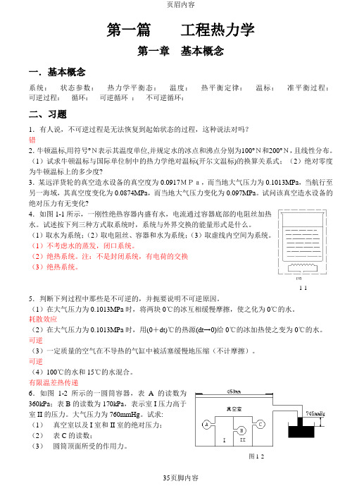
试问该真空造水设备的绝对压力有无变化?4.如图1-1所示,一刚性绝热容器内盛有水,电流通过容器底部的电阻丝加热水。
试述按下列三种方式取系统时,系统与外界交换的能量形式是什么。
(1)取水为系统;(2)取电阻丝、容器和水为系统;(3)取虚线内空间为系统。
(1)不考虑水的蒸发,闭口系统。
(2)绝热系统。
注:不是封闭系统,有电荷的交换(3)绝热系统。
图1-15.判断下列过程中那些是不可逆的,并扼要说明不可逆原因。
(1)在大气压力为0.1013MPa时,将两块0℃的冰互相缓慢摩擦,使之化为0℃的水。
耗散效应(2)在大气压力为0.1013MPa时,用(0+dt)℃的热源(dt→0)给0℃的冰加热使之变为0℃的水。
可逆(3)一定质量的空气在不导热的气缸中被活塞缓慢地压缩(不计摩擦)。
可逆(4)100℃的水和15℃的水混合。
有限温差热传递6.如图1-2所示的一圆筒容器,表A的读数为360kPa;表B的读数为170kPa,表示室I压力高于室II的压力。
大气压力为760mmHg。
试求:(1)真空室以及I室和II室的绝对压力;(2)表C的读数;(3)圆筒顶面所受的作用力。
图1-2第二章热力学第一定律一.基本概念功:热量:体积功:节流:二.习题1.膨胀功、流动功、轴功和技术功四者之间有何联系与区别?2.下面所写的热力学第一定律表达是否正确?若不正确,请更正。
热工基础(4.1.1)--第五章习题作业及答案

热工基础第五章作业题5-2 空气流经出口面积为A 2=10cm 2的渐缩喷管,喷管进口的空气参数为p 1=2.0MPa 、t l =80℃、c 1=150m/s ,背压p b =0.8MPa ,试求喷管出口处空气的流速和流经喷管的空气流量。
若喷管的速度系数为0.96,喷管的出口流速和流量又为多少?答案:(1)c 2=339.5 m/s ,q m =0.489 kg/s 。
(2)c 2’=325.9 m/s ,q m ’=0.462 kg/s 。
5-3 水蒸气经汽轮机中的喷管绝热膨胀,进入喷管的水蒸气参数p 1=0.9MPa 、t 1=525℃,喷管背压为p b =0.4MPa 、若流经喷管的质量流量q m =6kg/s ,试进行喷管的设汁计算。
答案:选缩放喷管,A cr =5.79 cm 2,A 2=5.99 cm 25-7 一锅炉锅筒,壁厚20mm ,外径0.6m ,热导率K)58W/(m •=λ,烟气温度C 10001°=t ,水温C 2002°=t 。
烟气到锅筒壁的总表面传热系数K)W/(m 16121•=h ,锅筒壁壁面到水的表面传热系数K)W/(m 232622•=h 。
求锅筒的热流密度和汽包外壁表面的温度。
若锅筒内壁表面结了一层5mm 的水垢,其热导率K)W/(m 312•=.λ,再求各值。
答案:无垢q =85150(W/m 2),t w1=269.3℃;结垢q =58800(W/m 2),t w 1=493.1℃;5-11一套管式换热器长2m ,外壳内径为6cm ,内管外径为4cm ,厚3mm 。
内管中流过冷却水,平均温度为40°C ,质量流量为0.0016m 3/s 。
平均温度70°C 的L-AN14润滑油流过环形空洞,质量流量为0.005 m 3/s 。
试计算内外壁面均洁净的传热系数值。
冷却水系经处理的冷却塔水,管壁材料为黄铜。
(油类被冷却时,层流换热可按1/30.14f w 1.86(/)(/)Nu RePrd l ηη=计算,定性温度为流体平均温度)。
工程热力学第三版课后习题答案

工程热力学第三版课后习题答案【篇一:工程热力学课后答案】章)第1章基本概念⒈闭口系与外界无物质交换,系统内质量将保持恒定,那么,系统内质量保持恒定的热力系一定是闭口系统吗? 答:否。
当一个控制质量的质量入流率与质量出流率相等时(如稳态稳流系统),系统内的质量将保持恒定不变。
⒉有人认为,开口系统中系统与外界有物质交换,而物质又与能量不可分割,所以开口系不可能是绝热系。
这种观点对不对,为什么?答:不对。
“绝热系”指的是过程中与外界无热量交换的系统。
热量是指过程中系统与外界间以热的方式交换的能量,是过程量,过程一旦结束就无所谓“热量”。
物质并不“拥有”热量。
一个系统能否绝热与其边界是否对物质流开放无关。
⒊平衡状态与稳定状态有何区别和联系,平衡状态与均匀状态有何区别和联系?答:“平衡状态”与“稳定状态”的概念均指系统的状态不随时间而变化,这是它们的共同点;但平衡状态要求的是在没有外界作用下保持不变;而平衡状态则一般指在外界作用下保持不变,这是它们的区别所在。
⒋倘使容器中气体的压力没有改变,试问安装在该容器上的压力表的读数会改变吗?在绝对压力计算公式p?pb?pe(p?pb); p?pb?pv(p?pb)中,当地大气压是否必定是环境大气压?答:可能会的。
因为压力表上的读数为表压力,是工质真实压力与环境介质压力之差。
环境介质压力,譬如大气压力,是地面以上空气柱的重量所造成的,它随着各地的纬度、高度和气候条件不同而有所变化,因此,即使工质的绝对压力不变,表压力和真空度仍有可能变化。
“当地大气压”并非就是环境大气压。
准确地说,计算式中的pb 应是“当地环境介质”的压力,而不是随便任何其它意义上的“大气压力”,或被视为不变的“环境大气压力”。
⒌温度计测温的基本原理是什么?答:温度计对温度的测量建立在热力学第零定律原理之上。
它利用了“温度是相互热平衡的系统所具有的一种同一热力性质”,这一性质就是“温度”的概念。
⒍经验温标的缺点是什么?为什么?答:由选定的任意一种测温物质的某种物理性质,采用任意一种温度标定规则所得到的温标称为经验温标。
工程热力学05章习题提示与答案.docx
习题提示与答案第五章热力学第二定律5-1蒸汽机中所用新蒸汽的温度为227 °C,排出乏汽的温度为100 °C,如按卡诺循环计算,试求其热效率。
提示:新蒸汽与乏汽的温度分别看做卡诺循环的高、低温热源温度。
答案:7ft = 0.254。
5-2海水表而温度为10 °C,而深处的温度为4 °C。
若设计一热机利用海水的表而和深处作为高温热源及低温热源并按卡诺循环工作,试求该热机的热效率。
提示:略。
答案:7t = 0.021 2 o5-3 一卡诺热机的热效率为40%,若它从高温热源吸热4 000 kJ/h,而向25 °C的低温热源放热,试求高温热源的温度及热机的功率。
提示:略。
答案:T ri =497K, P = 0.44 kWo5-4某内燃机每作出1 kW-h的功需消耗汽油514.8 go已知每千克汽油燃烧时町放出41 868 kJ的热量, 试求该内燃机的实际热效率。
提示:热机的吸热量等于燃料的放热量。
答案:— 0.167。
5-5有报告宣称某热机H 160 °C的热源吸热,向5 °C的低温环境放热,而在吸热1000kJ/h时可发出功率0.12 kWo试分析该报告的正确性。
提示:热机热效率不可能大于在相同温度范围内工作的卡诺热机的热效率。
答案:报告不正确,不可能实现。
5-6冇A 、B 两个卡诺热机,A 从温度为700 °C 的热源吸热,向温度为/的热源放热。
B 则从温度为啲热源取得-A 排岀的热量并向温度为100 °C 的热源放热。
试求:当两热机 的循环净功相同或两热机的热效率相同吋温度/的数值。
提示:答案:两热机循环净功相同时f = 400 °C,两热机热效率相同时严= 329.4 °C 。
5-7以氮气作为工质进行一个R 诺循坏,其高温热源的温度为1 000 K 、低温热源的温度为300 K ;在定温压缩过程中,氮气的压力由0.1 MPa 升高到0.4 MPa 。
第三版工程热力学课后思考题答案

第一章1、答:不一定。
稳定流动开口系统内质量也可以保持恒定。
2、答:这种说法是不对的。
工质在越过边界时,其热力学能也越过了边界。
但热力学能不是热量,只要系统和外界没有热量地交换就是绝热系。
3、答:只有在没有外界影响的条件下,工质的状态不随时间变化,这种状态称之为平衡状态。
稳定状态只要其工质的状态不随时间变化,就称之为稳定状态,不考虑是否在外界的影响下,这是他们的本质区别。
平衡状态并非稳定状态之必要条件。
物系内部各处的性质均匀一致的状态为均匀状态。
平衡状态不一定为均匀状态,均匀并非系统处于平衡状态之必要条件。
4、答:压力表的读数可能会改变,根据压力仪表所处的环境压力的改变而改变。
当地大气压不一定是环境大气压。
环境大气压是指压力仪表所处的环境的压力。
5、答:温度计随物体的冷热程度不同有显著的变化。
6、答:任何一种经验温标不能作为度量温度的标准。
由于经验温标依赖于测温物质的性质,当选用不同测温物质的温度计、采用不同的物理量作为温度的标志来测量温度时,除选定为基准点的温度,其他温度的测定值可能有微小的差异。
7、答:系统内部各部分之间的传热和位移或系统与外界之间的热量的交换与功的交换都是促使系统状态变化的原因。
8、答:(1)第一种情况如图1-1(a ),不作功(2)第二种情况如图1-1(b ),作功(3)第一种情况为不可逆过程不可以在p-v 图上表示出来,第二种情况为可逆过程可以在p-v 图上表示出来。
9、答:经历一个不可逆过程后系统可以恢复为原来状态。
系统和外界整个系统不能恢复原来状态。
10、答:系统经历一可逆正向循环及其逆向可逆循环后,系统恢复到原来状态,外界没有变化;若存在不可逆因素,系统恢复到原状态,外界产生变化。
11、答:不一定。
主要看输出功的主要作用是什么,排斥大气功是否有用。
第二章1、答:将隔板抽去,根据热力学第一定律w u q +∆=其中0,0==w q 所以容器中空气的热力学能不变。
工程热力学_曾丹苓_第五章气体的热力性质

工程热力学_曾丹苓_第五章气体的热力性质第五章气体的热力性质(4+实验2学时)1. 教学目标及基本要求掌握从热力学一般关系出发,导出理想气体特性的方法;熟悉理想气体性质(特性);认识实际气体性质的复杂性,了解实际气体性质的研究方法;掌握气体性质图表的查用方法;熟悉通用压缩因子图的使用。
2. 各节教学内容及学时分配5-1 理想气体性质(1学时)5-2 理想气体比热容及参数计算(1学时)5-3 实际气体状态方程(1学时)5-4 实际气体的比热容及焓、熵函数(0.5学时)★本章小结(0.5学时)** 实验课:空气c p(t)测定(2学时)3. 重点难点理想气体特性;平均比热容;对比态状态方程。
4. 教学内容的深化和拓宽范德瓦尔方程的理论意义。
5. 教学方式讲授,讨论,.ppt,例题6. 教学过程中应注意的问题本章没有太难的内容。
注意提醒学生:关于气体性质,要用宏观描述;平均比热容不能用于计算熵;理想气体的熵并非温度的单值函数!7. 思考题和习题思考题:教材的课后自检题(部分在课堂上讨论)习题:教材习题5,8,12,13,16(可变)8. 师生互动设计讲授中启发讨论:新工质(如新的制冷剂),无物性资料,怎么办?(对照第四章的同一问题)不用微观模型,理想气体的性质如何描述?9. 讲课提纲、板书设计第五章气体的热力性质理想气体微观模型:分子无体积;分子间无作用力理想气体宏观模型:用宏观热力性质描述(本章内容)实际气体:分子自身占有体积;分子间有作用力p →0时,实际气体→理想气体工程上,通常的参数范围内(相对温度来说压力很低,或相对压力来说温度很高时),一般的气体工质常可作理想气体处理(但饱和态附近的气体,例如湿蒸汽,不能当作理想气体)实际气体性质:可在理想气体基础上加以修正(本章内容)5-1 理想气体性质一、理想气体状态方程(Clapeyron 方程)m kg (n mol ) pV = mR g T = nRT1 kg pv = R g T1 mol pV m = RTR g —气体常数,J/(kg ·K)R = 8314 J/(kmol ·K) —通用气体常数(据Avogadro 假说)R g = R /MM = m /n kg/kmol —千摩尔质量二、理想气体的热系数特性αV = 1/T β = 1/T κT = 1/p c V = c V (T ) c p = c p (T ) c p – c V = R g μJ = 0三、理想气体的u 、h 特性du= c V (T )dTu = u (T ) dh= c p (T )dT h = h (T )四、理想气体的sds (T , v ) = c V dT/T+R g dv/vds (T , p ) = c p dT/T–R g dp/p5-2 理想气体c V 、c p 及?u 、?h 、?s 计算一、比热容的单位及换算名称符号单位质量比热容 c V c pJ/(kg ·K) 摩尔热容 C V ,m C p,mJ/(kmol ·K) 体(容)积热容C’V C’p J/(m3·K)二、c V (T )、c p (T )函数—查表(注意单位换算)dT T c h h h dT T c u u u T T p T T V )( , )(121212211221∫∫=?=?=?= 三、近似计算:定值比热容—查表(注意单位换算)12121212/ln /ln /ln /ln , p p R T T c v v R T T c s Tc h T c u g p g V p V ?=+=??=??=?四、平均比热容注意:根据定义,平均比热容不能用于?s 计算!5-3 实际气体状态方程纯实验的方法(不可靠)×实验得到热系数,再按热力学关系得到状态方程√理论分析(对理想气体做修正),实验确定修正系数或常数√对比态方法(基于相似理论)√修正:系数=实际/理想,余量=实际–理想一、范德瓦尔状态方程范德瓦尔气体:考虑实际气体分子占有体积(使活动空间↓);分子间有作用力(使撞击容器壁的力↓,撞击力的减小∝正在撞击器壁的分子数和未撞击器壁的分子数):p = R g T / (v – b ) –a ρ2 = R g T / (v – b ) – a /v 2用摩尔参数表达为 RT b V V a p V a b V RT p m m m m = +??=)( )(22或写成V m 的三次方程为 pV m 3 – (pb + RT )V m 2 + aV m – ab = 0★ .ppt 图示:范德瓦尔方程的意义:物质集态变化二、RK (瑞里奇-邝)方程,BB (贝蒂-布里奇曼)方程三、Virial (维里)方程(幂级数形式)四、对比态方程,通用压缩因子图物理现象相拟;热力学相似;对比参数;对应定律对比态状态方程 z = f (p r , T r )5-4 实际气体的比热容及焓、熵函数用热力学一般关系导得气体热力学能、焓、熵计算式的方法。
工程热力学第三版答案【英文】第5章
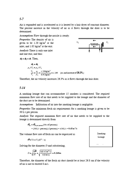
5-7Air is expanded and is accelerated as it is heated by a hair dryer of constant diameter. The percent increase in the velocity of air as it flows through the drier is to be determined.Assumptions Flow through the nozzle is steady. Properties The density of air is given to be 1.20 kg/m 3 at the inlet, and 1.05 kg/m 3 at the exit. Analysis There is only one inlet and one exit, and thusmm m 12==. Then,)of increase and (or, 1.263kg/m 0.95kg/m 1.2033211222112126.3% =====ρρρρV V AV AV m mTherefore, the air velocity increases 26.3% as it flows through the hair drier.5-14A smoking lounge that can accommodate 15 smokers is considered. The required minimum flow rate of air that needs to be supplied to the lounge and the diameter of the duct are to be determined.Assumptions Infiltration of air into the smoking lounge is negligible.Properties The minimum fresh air requirements for a smoking lounge is given to be 30 L/s per person.Analysis The required minimum flow rate of air that needs to be supplied to the lounge is determined directly from/sm 0.453=L/s 450= persons)person)(15L/s (30= persons)of No.(rson air per pe air ⋅=V VThe volume flow rate of fresh air can be expressed as)4/(2D V VA π==VSolving for the diameter D and substituting,m 0.268===m /s)(8)/s m 45.0(443ππVD VTherefore, the diameter of the fresh air duct should be at least 26.8 cm if the velocity of air is not to exceed 8 m/s.VSmokingLounge15 smokers5-20An air compressor compresses air. The flow work required by the compressor is to be determined.Assumptions 1 Flow through the compressor is steady. 2 Air is an ideal gas.Properties The gas constant of air is R = 0.287 kPa ⋅m 3/kg ⋅K (Table A-1).Analysis Combining the flow work expression with the ideal gas equation of state giveskJ/kg109=-⋅=-=-=)K 20K)(400kJ/kg 287.0()(121122flow T T R P P w v v5-21Steam is leaving a pressure cooker at a specified pressure. The velocity, flow rate, thetotal and flow energies, and the rate of energy transfer by mass are to be determined. Assumptions 1 The flow is steady, and the initial start-up period is disregarded. 2 The kinetic and potential energies are negligible, and thus they are not considered. 3 Saturation conditions exist within the cooker at all times so that steam leaves the cooker as a saturated vapor at 20 psia.Properties The properties of saturated liquid water and water vapor at 20 psia are v f = 0.01683 ft 3/lbm, v g = 20.093 ft 3/lbm, u g = 1081.8 Btu/lbm, and h g = 1156.2 Btu/lbm (Table A-5E).Analysis (a ) Saturation conditions exist in a pressure cooker at all times after the steady operating conditions are established. Therefore, the liquid has the properties of saturated liquid and the exiting steam has the properties of saturated vapor at the operating pressure. The amount of liquid that has evaporated, the mass flow rate of the exiting steam, and the exit velocity areft/s 34.1=⎪⎪⎭⎫⎝⎛⨯===⨯===∆==⎪⎪⎭⎫ ⎝⎛=∆=22233-33liquidft 1in 144in 0.15/lbm)ft 093lbm/s)(20. 10(1.765lbm/min 1059.0min45lbm 766.4lbm 766.4gal 1ft 13368.0/lbm ft 0.01683gal0.6c g c g f A m A m V t m m m v v V ρlbm/s101.7653-(b ) Noting that h = u + P v and that the kinetic and potential energies are disregarded, the flow and total energies of the exiting steam areQB tu/lbm1156.2B tu/lbm74.4=≅++==-=-==h pe ke h u h P e θ8.10812.1156flow vNote that the kinetic energy in this case is ke = V 2/2 = (34.1 ft/s)2 /2 = 581 ft 2/s 2 =0.0232 Btu/lbm, which is very small compared to enthalpy.(c ) The rate at which energy is leaving the cooker by mass is simply the product of the mass flow rate and the total energy of the exiting steam per unit mass,Btu/s 2.04=⨯==-Btu/lbm ) 6.2lbm /s)(115 10765.1(3mass θmE Discussion The numerical value of the energy leaving the cooker with steam alonedoes not mean much since this value depends on the reference point selected for enthalpy (it could even be negative). The significant quantity is the difference between the enthalpies of the exiting vapor and the liquid inside (which is h fg ) since it relates directly to the amount of energy supplied to the cooker.5-30Air is decelerated in an adiabatic diffuser. The velocity at the exit is to be determined. Assumptions 1 This is a steady-flow process since there is no change with time. 2 Air is an ideal gas with constant specific heats. 3 Potential energy changes are negligible. 4 There are no work interactions. 5 The diffuser is adiabatic.Properties The specific heat of air at the average temperature of (20+90)/2=55°C =328 K is c p = 1.007 kJ/kg ⋅K (Table A-2b ).Analysis There is only one inlet and one exit, and thus m m m==21. We take diffuser as the system, which is a control volume since mass crosses the boundary. The energybalance for this steady-flow system can be expressed in the rate form asoutin energiesetc. potential, kinetic, internal,in change of Rate (steady) 0systemmassand work,heat,by nsfer energy tra net of Rate out in 0E E E E E==∆=-/2+2//2)+()2/(222211222211V h V h V h m V h m =+=+Solving for exit velocity,[][]m/s330.2=⎥⎥⎦⎤⎢⎢⎣⎡⎪⎪⎭⎫ ⎝⎛-⋅+=-+=-+=5.02225.021215.021212kJ/kg 1/s m 1000)K90K)(20kJ/kg 007.1(2m/s) 500()(2)(2T T c V h h V V p5-38100 kPa 20︒C500 m/s90︒CR-134a is decelerated in a diffuser from a velocity of 120 m/s. The exit velocity of R-134a and the mass flow rate of the R-134a are to be determined.Assumptions 1 This is a steady-flow process since there is no change with time. 2 Potential energy changes are negligible. 3 There are no work interactions. Properties From the R-134a tables (Tables A-11 through A-13) kJ/kg 267.29/kgm 0.025621.kPa 8001311==⎭⎬⎫=h vapor sat P v andkJ/kg 274.17/kgm 0.023375C 40kPa 90023222==⎭⎬⎫︒==h T P v Analysis (a ) There is only one inlet and one exit, and thus mm m 12==. Then the exit velocity of R-134a is determined from the steady-flow mass balance to be()m/s 60.8===−→−=m/s 120/kg)m (0.025621/kg)m (0.0233751.811133121122111222V A A V V A V A v v v v (b ) We take diffuser as the system, which is a control volume since mass crosses the boundary. The energy balance for this steady-flow system can be expressed in the rate form asoutin energiesetc. potential, kinetic, internal,in change of Rate (steady) 0systemmassand work,heat,by nsfer energy tra net of Rate out in 0E E E E E==∆=-⎪⎪⎭⎫⎝⎛-+-=≅∆≅=++20)pe W (since /2)V +()2/(212212in 222211inV V h h mQ h m V h m QSubstituting, the mass flow rate of the refrigerant is determined to be()⎪⎪⎭⎫ ⎝⎛⎪⎪⎭⎫ ⎝⎛-+-=2222/s m 1000kJ/kg 12m /s) (120m /s 60.8kg 267.29)kJ/(274.17kJ/s 2m It yieldskg/s 1.308=m5-46Steam expands in a turbine. The change in kinetic energy, the power output, and theturbine inlet area are to be determined.Assumptions 1 This is a steady-flow process since there is no change with time.212Potential energy changes are negligible. 3 The device is adiabatic and thus heat transfer is negligible.Properties From the steam tables (Tables A-4 through 6) kJ/kg3178.3/kgm 0.047420C 400MPa 613111==⎭⎬⎫︒==h T P v andkJ/kg 2318.52392.10.9262.31792.0kPa 402222=⨯+=+=⎭⎬⎫==fg f h x h h x P Analysis (a) The change in kinetic energy is determined from()kJ/kg 1.95-=⎪⎪⎭⎫⎝⎛-=-=∆22222122/s m 1000kJ/kg12m /s) (80m /s 502V V ke(b ) There is only one inlet and one exit, and thus mm m 12==. We take the turbine as the system, which is a control volumesince mass crosses the boundary. The energy balance for this steady-flow system can be expressed in the rate form asoutin energiesetc. potential, kinetic, internal,in change of Rate (steady) 0systemmassand work,heat,by nsfer energy tra net of Rate out in 0E E E E E==∆=-⎪⎪⎭⎫⎝⎛-+--=≅∆≅+=+20)pe Q (since /2)+()2/(212212out 222out211V V h h mW V h m W V h mThen the power output of the turbine is determined by substitution to beMW 14.6==---=kW 14,590kJ/kg )1.953178.32318.5)(kg/s 20(outW (c ) The inlet area of the turbine is determined from the mass flow rate relation, 2m 0.0119===−→−=m/s80)/kg m 0.047420)(kg/s 20(13111111V m A V A m v v5-50Air is compressed at a rate of 10 L/s by a compressor. The work required per unitmass and the power required are to be determined.Assumptions 1 This is a steady-flow process since there is no change with time.2P 1 = 6 MPa T 1 = 400︒CV 1P 2 = 40 kPa x 2 = 0.92 V 2 = 50 m/sKinetic and potential energy changes are negligible. 3 Air is an ideal gas with constant specific heats.Properties The constant pressure specific heat of air at the average temperature of (20+300)/2=160°C=433 K is c p = 1.018 kJ/kg·K (Table A-2b). The gas constant of air is R = 0.287 kPa ⋅m 3/kg ⋅K (Table A-1).Analysis (a ) There is only one inlet and one exit, and thus m m m==21. We take the compressor as the system, which is a control volume since mass crosses the boundary.The energy balance for this steady-flow system can be expressed in the rate form aso u tin energiesetc. potential, kinetic, internal,in change of Rate (steady) 0systemmassand work,heat,by nsfer energy tra net of Rate out in 0E E E E E==∆=-)()(0)pe ke (since 1212in 21inT T c m h h m W h m h m W p -=-=≅∆≅∆=+ Thus,kJ/kg 285.0=-⋅=-=0)K 2K)(300kJ/kg (1.018)(12in T T c w p(b ) The specific volume of air at the inlet and the mass flow rate are/kg m 7008.0kPa120K) 273K)(20/kg m kPa 287.0(33111=+⋅⋅==P RT vkg/s 0.01427/kgm 0.7008/s m 010.03311===v V m Then the power input is determined from the energy balance equation to bekW 4.068=-⋅=-=0)K 2K)(300kJ/kg 8kg/s)(1.01 (0.01427)(12inT T c m W p5-65Steam is throttled by a well-insulated valve. The temperature drop of the steam afterthe expansion is to be determined.Assumptions 1 This is a steady-flow process since there is no change with time. 2 Kinetic and potential energy changes are negligible. 3 Heat transfer to or from the fluid is negligible. 4 There are no work interactions involved. Properties The inlet enthalpy of steam is (Tables A-6),kJ/kg 1.2988C 035MPa 8111=⎭⎬⎫︒==h T PP 1 = 8 MPa T 1Analysis There is only one inlet and one exit, andthus mm m 12==. We take the throttling valve as the system, which is a control volume since mass crosses the boundary. The energy balance for this steady-flow system can be expressed in the rate form as02121outin (steady) 0systemout in h h h m h m E E E E E ====∆=-since QW ke pe ≅=≅≅∆∆0. Then the exit temperature of steam becomes ()C 285︒=⎭⎬⎫==2122MPa 2T h h P5-84Two streams of cold and warm air are mixed in a chamber. If the ratio of hot to coldair is 1.6, the mixture temperature and the rate of heat gain of the room are to be determined.Assumptions 1 This is a steady-flow process since there is no change with time. 2 Kinetic and potential energy changes are negligible. 3 There are no work interactions. 4 The device is adiabatic and thus heat transfer is negligible. Properties The gas constant of air is R = 0.287 kPa.m 3/kg.K. The enthalpies of air are obtained from air table (Table A-17) ash 1 = h @280 K = 280.13 kJ/kg h 2 = h @ 307 K = 307.23 kJ/kg h room = h @ 297 K = 297.18 kJ/kg Analysis (a ) We take the mixing chamber as the system, which is a control volume since mass crosses the boundary. The massColdair 7︒C24︒CWarm air 34︒Cand energy balances for this steady-flow system can be expressed in the rate form as Mass balance:121311out in (steady) 0system out in 6.1 since 6.26.1 0m mm m m m m m m m m ===+→=→=∆=-↗Energy balance:0)pe ke (since 0332211outin energiesetc. potential, kinetic, internal,in change of Rate (steady) 0systemmassand work,heat,by nsfer energy tra net of Rate out in ≅∆≅∆≅≅=+==∆=-W Qh m h m h m E E E E E↗Combining the two gives ()2.3/2.22.32.2213312111h h h or h m h m h m+==+ Substituting, h 3 = (280.13 +2.2⨯ 307.23)/3.2 = 298.76 kJ/kg From air table at this enthalpy, the mixture temperature isT 3 = T @ h = 298.76 kJ/kg = 298.6 K = 25.6︒C (b ) The mass flow rates are determined as followskg/s.1363kg/s) 9799.0(2.32.3kg/s 9799.0/kg m 0.7654/s m 0.75kg/m 7654.0kPa 105K)273K)(7/kg m kPa (0.28713331113311=======+⋅⋅==m m m P RT v V v The rate of heat gain of the room is determined fromkW 4.93-=-=-=kJ/kg )76.29818.297(kg/s) 136.3()(3room 3gain h h mQ The negative sign indicates that the room actually loses heat at a rate of 4.93 kW.5-102A room is to be heated by an electric resistance heater placed in a duct in the room. The power rating of the electric heater and the temperature rise of air as it passes through the heater are to be determined.Assumptions 1 Steady operating conditions exist. 2 Air is an ideal gas with constant specific heats at room temperature. 3 Kinetic and potential energy changes are negligible. 4 The heating duct is adiabatic, and thus heat transfer through it is negligible. 5 No air leaks in and out of the room.Properties The gas constant of air is 0.287 kPa.m 3/kg.K (Table A-1). The specific heats of air at room temperature are c p = 1.005 and c v = 0.718 kJ/kg·K (Table A-2). Analysis (a ) The total mass of air in the room iskg 284.6)K 288)(K /kg m kPa 0.287()m 240)(kPa 98(m240m 865331133=⋅⋅===⨯⨯=RT P m V VWe first take the entire room as our system,which is a closed system since no mass leaks in or out. The power rating of the electric heater is determined by applying the conservation of energy relation to this constant volume closed system:()()12avg ,out in fan,in e,in fan,in e,energiesetc. potential, kinetic, internal,in Change system massand work,heat,by nsfer energy tra Net 0)=PE =KE (since T T mc Q W W t U Q W W E E E out out in -=-+∆∆∆∆=-+∆=-vSolving for the electrical work input giveskW5.40=⨯-⋅+-=∆--=+s) 60C/(15)1525)(C kJ/kg 0.718)(kg 284.6()kJ/s 0.2()kJ/s 200/60(/)(12in fan,out in e, tT T W Q W mc v (b ) We now take the heating duct as the system, which is a control volume since masscrosses the boundary. There is only one inlet and one exit, and thus mm m 12==. The energy balance for this adiabatic steady-flow system can be expressed in the rate formas)()(0)pe ke (since 01212in fan,in e,21in fan,in e,energiesetc. potential, kinetic, internal,in change of Rate (steady) 0systemmassand work,heat,by nsfer energy tra net of Rate T T c m h h mW W Q h m h mW W E E E E E p outin out in -=-=+≅∆≅∆==++==∆=-Thus, ()()C 6.7 =⋅+=+=-=∆K kJ/kg 1.005kg/s 50/60kJ/s )2.040.5(infan,in e,12p c m W W T T T5-107R-134a is condensed in a condenser. The heat transfer per unit mass is to bedetermined.Assumptions 1 This is a steady-flow process since there is no change with time. 2 Kinetic and potential energy changes are negligible. 3 There are no work interactions. Analysis We take the pipe in which R-134a is condensed as the system, which is a control volume. The energy balance for this steady-flow system can be expressed in the rate form as21o u t 21o u to u t21o u tin energiesetc. potential, kinetic, internal,in change of Rate (steady) 0systemmassand work,heat,by nsfer energy tra net of Rate out in )(0h h q h h m QQ h m h m E E E E E -=-=+===∆=-The enthalpies of R-134a at the inlet and exit of the condenser are (Table A-12, A-13).kJ/kg61.1010kP a 900kJ/kg13.295C 60kP a 900kPa 900@22111==⎭⎬⎫===⎭⎬⎫︒==f h h x P h T PSubstituting,kJ/kg 193.5=-=61.10113.295out q5-112Helium flows from a supply line to an initially evacuated tank. The flow work of the helium in the supply line and the final temperature of the helium in the tank are to be determined.Properties The properties of helium are R = 2.0769 kJ/kg.K, c p = 5.1926 kJ/kg.K, c v = 3.1156 kJ/kg.K (Table A-2a).Analysis The flow work is determined from its definition but we first determine the specific volume/kg m 0811.4kP a)200(K)27320kJ/kg.K)(1 0769.2(3line =+==P RT vkJ/kg816.2===/kg)m 1kPa)(4.081 200(3flow v P wNoting that the flow work in the supply line is converted to sensible internal energy in the tank, the final helium temperature in the tank issat. liq.60︒Cdetermined as followsK655.0=−→−=−→−==+===tank tank tank tank -line line linetank kJ/kg.K) 1156.3(kJ/kg 7.2040kJ/kg7.2040K) 27320kJ/kg.K)(1 1926.5(T T T c u T c h h u p vAlternative Solution : Noting the definition of specific heat ratio, the final temperature in the tank can also be determined fromK 655.1=+==K) 273120(667.1line tank kT T which is practically the same result.5-119A rigid tank initially contains superheated steam. A valve at the top of the tank is opened, and vapor is allowed to escape at constant pressure until the temperature rises to 500︒C. The amount of heat transfer is to be determined.Assumptions 1 This is an unsteady process since the conditions within the device are changing during the process, but it can be analyzed as a uniform-flow process by using constant average properties for the steam leaving the tank. 2 Kinetic and potential energies are negligible. 3 There are no work interactions involved. 4 The direction of heat transfer is to the tank (will be verified). Properties The properties of water are (Tables A-4 through A-6)kJ/kg3468.3,kJ/kg 3116.9/kgm 0.17568C 500MP a 2kJ/kg3024.2,kJ/kg 2773.2/kgm 0.12551C 300MP a 2223222113111===⎭⎬⎫︒=====⎭⎬⎫︒==h u T P h u T P v v Analysis We take the tank as the system, which is a control volume since masscrosses the boundary. Noting that the microscopic energies of flowing and nonflowing fluids are represented by enthalpy h and internal energy u , respectively, the mass and energy balances for this uniform-flow system can be expressed as Mass balance :21system out in m m m m m m e -=→∆=-Energy balance :)0 (since 1122in energiesetc. potential, kinetic,internal,in Change system massand work,heat,by nsfer energy tra Net out in ≅≅≅-=-∆=-pe ke W u m u m h m Q E E E e eThe state and thus the enthalpy of the steam leaving the tank is changing during thisprocess. But for simplicity, we assume constant properties for the exiting steam at the average values. Thus,kJ/kg 3246.22kJ/kg3468.33024.2221=+=+≅h h h e The initial and the final masses in the tank arekg 1.138/kgm 0.17568m 0.2kg1.594/kg m 0.12551m 0.23322233111======v V v V m mThen from the mass and energy balance relations,kg 0.456138.1594.121=-=-=m m m e()()()()()()kJ606.8=-+=-+=kJ/kg 2773.2kg 1.594kJ/kg 3116.9kg 1.138kJ/kg 3246.2kg 0.4561122u m u m h m Q e e in5-131An insulated piston-cylinder device with a linear spring is applying force to the piston. A valve at the bottom of the cylinder is opened, and refrigerant is allowed to escape. The amount of refrigerant that escapes and the final temperature of the refrigerant are to be determined.Assumptions 1 This is an unsteady process since the conditions within the device are changing during the process, but it can be analyzed as a uniform-flow process assuming that the state of fluid leaving the device remains constant. 2 Kinetic and potential energies are negligible.Properties The initial properties of R-134a are (Tables A-11 through A-13)kJ/kg11.354kJ/kg 03.325/kg m 02423.0C 120MPa 2.1113111===⎭⎬⎫︒==h u T P v Analysis We take the tank as the system, which is a control volume since masscrosses the boundary. Noting that the microscopic energies of flowing and nonflowing fluids are represented by enthalpy h and internal energy u , respectively, the mass and energy balances for this uniform-flow system can be expressed as Mass balance : 21system out in m m m m m m e -=→∆=- Energy balance :)0 (since 1122in b,energiesetc. potential, kinetic,internal,in Change system massand work,heat,by nsfer energy tra Net out in ≅≅≅-=-∆=-pe ke Q u m u m h m W E E E e e23212322233111m 0.502.33m 0.5kg02.33/kgm 0.02423m 0.8v v V v V -=-======m m m v m m eNoting that the spring is linear, the boundary work can be determined fromkJ 270m 0.5)-0.8(2kPa600)(1200)(232121in b,=+=-+=V V P P W Substituting the energy balance,kJ/kg) kg)(325.03 02.33(m 5.0m 5.002.3327022323-⎪⎪⎭⎫ ⎝⎛=⎪⎪⎭⎫ ⎝⎛--u h e v v (Eq. 1) where the enthalpy of exiting fluid is assumed to be the average of initial and finalenthalpies of the refrigerant in the cylinder. That is,2kJ/kg) 11.354(2221h h h h e +=+=Final state properties of the refrigerant (h 2, u 2, and v 2) are all functions of finalpressure (known) and temperature (unknown). The solution may be obtained by a trial-error approach by trying different final state temperatures until Eq. (1) is satisfied. Or solving the above equations simultaneously using an equation solver with built-in thermodynamic functions such as EES, we obtainT 2 = 96.8︒C , m e = 22.47 kg, h 2 = 336.20 kJ/kg, u 2 = 307.77 kJ/kg, v 2 = 0.04739 m 3/kg, m 2 = 10.55 kg。
工程热力学第五章 习题解答

第五章 习题解答5-1 ⑴ 12,187331364.14%873t c T T T η--===⑵ 0,10.641410064.14 kW t c W Q η==⨯= ⑶ ()()2,1110.641410035.86 kW t c Q Q η=-=-⨯= 5-2 12,1100040060%1000t c T T T η--=== 0,10.61000600 kJ < 700 kJ t c W Q η==⨯= 该循环发动机不能实现5-3 ()()121 1.011000300707 kJ/kg p q c T T =-=⨯-=133323331221.41.41lnln ln 300 0.287300ln 362.8 kJ/kg1000p pT q RT RT RT p p T κκ--⎛⎫=== ⎪⎝⎭⎛⎫=⨯⨯=- ⎪⎝⎭12707362.8344.2 kJ/kg w q q =+=-=1344.248.68%707w q η=== 5-4 12,1100030070%1000t c T T T η--=== ,10.7707495 kJ/kg t c w q η==⨯= 5-5 ⑴221126310000089765 kJ/h 293T Q Q T ==⨯= ⑵12,122939.77293263c T T T ε===-- 12,1000002.84 kW 9.773600cQ P ε===⨯⑶100000100000 kJ/h 27.78 kW 3600P ===5-6 ⑴12,1229314.65293273c T T T ε===-- 12,2010000.455 kW 9.773600cQ P ε⨯===⨯由()1221212003600T T T PT T -⨯=-220t =℃ 得1313 K 40T ==℃5-7 2,10.351000015000 kJ/h t c Q Q ηε==⨯⨯= 5-8 ()()2111000010.37000 kJ/h t Q Q η=-=⨯-=215000700022000 kJ/h Q Q Q =+=+=总 5-9 可逆绝热压缩终态温度2T1 1.411.422110.3300410.60.1p T T p κκ--⎛⎫⎛⎫==⨯= ⎪⎪⎝⎭⎝⎭K可逆过程0Q U W =∆+=,不可逆过程0Q U W ''=∆+= 且 1.1W W '=,则 1.1U U '∆=∆()()21211.1v v mc T T mc T T '-=-()()21211.1300 1.1410.6300421.7T T T T '=+-=+⨯-=K 2211421.70.3ln ln 0.1 1.01ln 0.287ln 3000.1p T p S m c R T p '⎛⎫⎛⎫∆=-=⨯- ⎪ ⎪⎝⎭⎝⎭=0.00286 kJ/kg.K5-10 理论制冷系数:21,122587.37293258c T T T ε===-- 制冷机理论功率:21,1257004.74 kW 7.373600cQ P ε===⨯散热量:12125700 4.743600142756 kJ/h Q Q P =+=+⨯=冷却水量:21H O 1427564867.2 kg/h 4.197Q mc t ===∆⨯5-11 ⑴ 1111003070 kJ W Q U =-∆=-=热源在完成不可逆循环后熵增0.026kJ/kg.K 则第二个过程热源吸热:120.0261006000.026115.6 kJ Q Q T T ⎛⎫=+=+⨯= ⎪⎝⎭工质向热源放热:()22115.63085.6 kJ W Q U =-∆=---=- 5-12 可逆定温压缩过程熵变:211ln0.287ln 0.66 kJ/kg K 0.1p s R p ∆=-=-⨯=-⋅ 可逆过程耗功:1120.1ln0.287400ln 264 kJ/kg 1p w RT p ==⨯⨯=- 实际耗功:()1.25 1.25264330 kJ/kg w w '==⨯-=- 因不可逆性引起的耗散损失:()33026466 kJ/kg q w w ''=-=---=- 总熵变:0660.660.44 kJ/kg K 300q s s T ''∆=∆+=-+=-⋅ 5-13 ()121v q c T T =-,()231p q c T T =-()()31313121121212111111111p v c T T T T v v q wq q c T T T T p p ηκκ---==-=-=-=---- 5-14 1112lnp q RT p =,()421223ln v pq c T T RT p =-+ ()412412223321111122lnln 1111lnlnv p T T pc T T RT T p p q p p q RT T p p κη--++-=-=-=-5-15 ⑴11940 K T '=,2660 K T '=216601166%1940T T η'=-=-=' ⑵01100066%660 kJ W Q η==⨯=20,max11600110001700 kJ 2000T W Q T ⎛⎫⎛⎫=-=⨯-= ⎪ ⎪⎝⎭⎝⎭0,max 0700660 kJ 40 kJ W W W δ=-=-=5-16 11114000.10.445 kg 0.287313p V m RT ⨯===⨯ 22222000.10.238 kg 0.287293p V m RT ⨯===⨯ ()()11220v v U m c T T m c T T ∆=-+-=1122120.4453130.238293306 K 0.4450.238m T m T T m m +⨯+⨯===++()()12120.4450.2380.2873060.3 MPa 0.10.1m m RT p V V ++⨯⨯===++ 1122121122 ln ln ln ln 3060.3 0.4451.01ln 0.287ln 3130.43060.3 0.2381.01ln 0.287ln 0.0093 kJ/K2930.2p p S m s m s T p T p m c R m c R T p T p ∆=∆+∆⎛⎫⎛⎫=-+- ⎪ ⎪⎝⎭⎝⎭⎛⎫=⋅-⋅ ⎪⎝⎭⎛⎫+-⋅= ⎪⎝⎭5-17 ⑴2211400 2.51000 K pT T p ==⨯=()()1210.7231000400433.8 kJ/kg v q c T T =-=⨯-=12331ln 0.287400ln 264.3 kJ/kg 10v q RT v ==⨯=-⑵12433.8264.3169.5 kJ/kg w q q =-=-=21264.31139.0%433.8q q η=-=-=5-18 ⑴()12201s R T T W m w m κκκ'-===- ()()21201201.41298258.2 K 0.5 1.40.287T T m R κκ'--=-=-=⨯⨯⑵1 1.412 1.42112980.4229.4 K p T T p κκ--⎛⎫==⨯= ⎪⎝⎭()()120.287298229.40.5 1.41 1.4134.5 kWs R T T W m w m κκκ-⨯-===⨯⨯--= 5-19 1 1.311.322111303515.5 K 0.1n np T T p --⎛⎫⎛⎫==⨯= ⎪ ⎪⎝⎭⎝⎭()()21 1.3 1.40.287515.53031 1.31 1.4150.8 kJ/kgv n q c T T n κ--=-=⨯⨯----=- 环境熵变:1050.80.175 kJ/kg K 290q s T ∆===⋅空气熵变:22211ln ln p T ps c R T p ∆=-515.511.005ln 0.287ln 0.127 kJ/kg K 3030.1=⨯-=-⋅孤立系统熵变:120.1750.1270.048 kJ/kg K iso s s s ∆=∆+∆=-=⋅ 5-20 1 1.411.422110.2800505.1 K 1p T T p κκ--⎛⎫⎛⎫==⨯= ⎪ ⎪⎝⎭⎝⎭()()120.2968800505.1218.8 kJ/kg 1 1.41R T T w κ-⨯-===--()()()12120210212112021 505.1800 218.81000.2968167.6 kJ/kg2001000u u v ex ex u u p v v T s s RT RT c T T p p p -=---+-⎛⎫=--- ⎪⎝⎭⎛⎫=-⨯⨯-= ⎪⎝⎭排开环境所作的功为作功能力损失(51.2kJ/kg )5-21 1 1.211.222110.2800611.8 K 1n np T T p --⎛⎫⎛⎫==⨯= ⎪⎪⎝⎭⎝⎭()()120.2968800611.8279.3 kJ/kg 1 1.21R T T w n -⨯-===--31110.29688000.237 m /kg 1000RT v p ⨯=== 32220.2968611.80.908 m /kg 200RT v p ⨯=== 22221111ln ln ln ln 11.40.2968611.80.2ln 0.2968ln 0.20 kJ/kg K1.418000.1p T p T p R s c R R T p T p κκ∆=-=--⨯=-=⋅-()()()()()()1212021021120210 10.2968 800611.81000.9080.2373000.21.41 132.5 kJ/kg u u ex ex u u p v v T s s RT T p v v T s κ-=---+-=---+∆-=⨯--⨯-+⨯-= 5-22 1112001013.94 kg 0.287500pV m RT ⨯===⨯ ()()2113.94 1.0056005001400.7 kJ p Q mc T T =-=⨯⨯-=21600ln1.005ln 0.1832 kJ/kg K 500p T s c T ∆==⨯=⋅ 01400.730013.940.1832634.6 kJ q Ex Q T m s =-⋅∆=-⨯⨯= 030013.940.1832766.1 kJ q An T m s =⋅∆=⨯⨯=5-23 ()()12 1.40.287500320180.74 kJ/kg 1 1.41s R T T w κκ-⨯⨯-===--22113200.1lnln 1.005ln 0.287ln 5000.5 0.0134 kJ/kg Kp T p s c R T p ∆=-=⨯-⨯=⋅()()()1212021120 1.0055003203000.0134184.92 kJ/kgh h p ex ex h h T s s c T T T s -=-+-=-+∆=⨯-+⨯=12180.7497.7%184.92s ex h h w ex ex η===-5-24 ⑴21300201167.3%100020T T η'+=-=-='- ⑵013001170%1000t T T η=-=-= ()()110000.70.67327 kJ t L Q ηη=-=⨯-= ⑶()()211100010.673327 kJ Q Q η=-=⨯-=12110211111111 10003270.09 kJ/K9801000300320S Q Q T T T T ⎛⎫⎛⎫∆=-+- ⎪⎪''⎝⎭⎝⎭⎛⎫⎛⎫=-+-= ⎪ ⎪⎝⎭⎝⎭0iso 3000.0927 kJ L T S =∆=⨯= 符合!。
- 1、下载文档前请自行甄别文档内容的完整性,平台不提供额外的编辑、内容补充、找答案等附加服务。
- 2、"仅部分预览"的文档,不可在线预览部分如存在完整性等问题,可反馈申请退款(可完整预览的文档不适用该条件!)。
- 3、如文档侵犯您的权益,请联系客服反馈,我们会尽快为您处理(人工客服工作时间:9:00-18:30)。
工程热力学第三版第五章曾丹苓答案
第一题
问题:为什么工程热力学中熵函数可以视为状态参量?
在工程热力学中,熵函数是一个很重要的物理量,它可以用于描述系统的无序程度和能量分布均匀程度。
熵函数被定义为系统的状态参量,因为它只取决于系统的初始状态和终态,并且与路径无关。
其原因可以从以下两个方面解释:
1.熵函数的数学性质:熵函数具有可加性和广延性的
数学性质。
对于一个复合系统,其熵等于各个组成部分的熵之和。
这个性质导致熵函数可以作为状态参量来描述系统的热力学状态。
2.熵函数与平衡态:在平衡态下,系统的熵函数达到
最大值,这也是热力学第二定律的表述之一。
因此,熵函数可以作为判断系统是否处于平衡态的指标。
综上所述,由于熵函数具有可加性、广延性和与平衡态的关系,使得熵函数在工程热力学中可以被视为状态参量。
问题:怎样理解熵的微观本质?
熵在工程热力学中是一个非常重要的概念,它可以用来描述系统的无序程度和能量分布均匀程度。
从微观的角度来理解熵的本质,可以有以下几个方面的解释:
1.微观粒子的随机运动:根据统计力学的角度,熵可
以理解为微观粒子的随机运动的度量。
微观粒子的随机运动越强烈,系统的熵越大,即系统的无序程度越高。
2.能量的分布均匀性:熵还可以理解为系统中能量的
分布均匀程度的度量。
当系统中能量更加均匀地分布时,系统的熵将会增加。
3.系统的信息量:熵还可以解释为系统中所包含的信
息量。
当一个系统的状态可能性更多时,它所包含的信息量也就越大,此时系统的熵也会增加。
因此,从微观角度来理解,熵可以看作是微观粒子的随机运动、能量分布均匀性和系统的信息量所耦合的结果。
问题:什么是可逆过程和不可逆过程?
在工程热力学中,可逆过程和不可逆过程是描述系统变化
方式的两个重要概念。
可逆过程是指系统从一个热力学平衡态通过一系列连续的
无限小的热力学平衡态经过的过程。
在可逆过程中,系统的每一个状态都可以与外界的环境达到瞬时的热力学平衡。
可逆过程是理论上的概念,意味着系统在整个过程中没有任何内部或外部的不均匀分布或不均匀性。
不可逆过程是指系统从一个热力学平衡态到另一个热力学
平衡态的过程,但过程中无法保持系统与外界的热力学平衡。
在不可逆过程中,系统的状态发生了不可逆的变化,不能通过微小的变化来恢复原来的状态。
不可逆过程通常与能量的转化和传递不完全相关。
可逆过程和不可逆过程之间的区别在于系统与外界是否达
到热力学平衡。
可逆过程要求系统与外界始终保持热力学平衡,而不可逆过程则允许系统与外界的热力学平衡破坏。
问题:什么是热力学第二定律?
热力学第二定律是热力学中的一个重要定律,它揭示了自然界中能量转化和能量传递的规律。
热力学第二定律有以下两种等价的表述方式:
1.克劳修斯表述:不可能把热量从低温物体自发地传
递给高温物体,而不产生其他效果。
换句话说,热量不能自发地由低温物体传输到高温物体。
2.开尔文表述:不可能通过一个循环过程完成工作并
使系统从单一热源吸收热量,然后将这些热量全部转化为有用的工作,并使系统回到原始状态。
换句话说,不可能通过一个循环过程将热量完全转化为有用的工作。
热力学第二定律可以用来判断系统是否处于平衡态。
根据热力学第二定律,系统朝着熵增加的方向进行变化,只有在平衡态下,系统的熵才能达到最大值。
第五题
问题:热力学第二定律的意义是什么?
热力学第二定律是热力学中的一个非常重要的定律,它揭示了自然界中能量转化和能量传递的规律。
热力学第二定律具有以下几个重要的意义:
1.限制了能量转化的效率:热力学第二定律确定了能
量转化的最大效率。
根据开尔文表述,不可能通过一个循环过程将热量完全转化为有用的工作。
这意味着能量转化会伴随着能量的浪费和损失。
2.定义了时间的箭头:根据热力学第二定律,系统的
熵朝着增加的方向进行变化,而不会自发地减少。
这定义了时间的箭头,说明了自然界中的物理过程具有时间的不可逆性。
3.确定了平衡态和不平衡态之间的关系:热力学第二
定律揭示了平衡态和不平衡态之间的关系。
只有在平衡态下,系统的熵才能达到最大值。
而不平衡态则表明系统还存在一定的能量分布不均匀性和无序程度。
综上所述,热力学第二定律限制了能量转化的效率,定义了时间的箭头,并确定了平衡态和不平衡态之间的关系,对于理解自然界中的能量转化和平衡态具有重要意义。
注意:本文档采用Markdown文本格式编写,可以方便地转换为HTML、PDF等其他格式,以便更好地展示和阅读。