AEX2200双通道激励器方法及要点
百灵达EX2200激励器的工作原理及使用方法

2002 年第三期 www.av-2000.com
行补偿(接在录音机前),然后再将经激励器处理过的 信号录在磁带上,这样就可以大大地提高了磁带复制 率(转录次数),保证了磁带录音的重放音质。有时,音 源本身由于保存时间过长和信号传送等方面的原因, 也会使高低音噪声过大或声音信号频带不够宽,这时 可用均衡器将高低音噪声滤掉,再用激励器对高低音 进行补偿,录音质量可以显著提高。
调节步骤:1.IN/OUT 放在 IN ,表示加激励。2 . T U N E 放在 1 2 点位置。3 . P R O C E S S 根据实际需要调 节。 4.HIGH MIX 调到最小。5.LOW MIX 放在 12 点 位置。6. 提升 HIGH MIX,直到听到有镶边声(声音 变亮)。7. 调 TUNE ,用以改善或突出某个声音的音色 或穿透力。8.调 LOW MIX,根据需要改变低音的软硬 度。9 . 用 IN/OUT 对比加与不加激励的声音效果。如 不理想,可反复调整,直到高低音均满意为止。
电压×电流 = 功率 开关式功率放大器的输出级工作于开或关的两种 状态时电压与电流中有一项为 0 或接近于 0,所以器件 上的功率消耗也接近于 0。当然,还有一种状态就是由 开到关或者是由关到开的转换状态,这个过程处于和
低频的有用声音也会被一同滤掉,这没有关系,可以再 用激励器造出失去的有用高音与低音,达到了降低噪 音,又保证音质的目的。
音
响 技
专业音响
术
百灵达 EX2200 激励器的工作原理及使用方法
激励器是一种改善声音音色、提高声音穿透力的 信号处理设备。它将原声中的基波进行选频后送入谐 波发生器,制造出该频率的谐波成分,再将这些高频谐 波成分加回到原声中去,以加强原声的谐波量。由于声 音音色是由基波和谐波成分构成的,高频谐波不仅对 音色如何起到了决定性作用,其含量多少还决定了声 音穿透力的强弱,所以,声音中高频谐波量的增加,必 然会使声音的音色和穿透力明显改善。音色是衡量音 响系统音质的一个十分重要依据,音色好的设备,音色 纯正且优美动听;反之则听起来干涩无味。但在声音录 制、处理、放大和转换过程中,由于种种原因,会造成 谐波成分的损失;有时音响师也需要对声音谐波量加 以调节,以求对声音音色和穿透力进行控制。所以,激 励器是现代音响所必须具备的设备,它的作用是任何 频率处理设备所无法替代的。虽然均衡器可以提升或 衰减某些频率的声音,但它绝对不能创造出某些频率 的声音,一旦声音中没有某些频率,均衡器是无能为 力、力不从心的,即使提升,结果也只能是增加了噪声。 而激励器可以根据需要创造出特定的谐波成分,并将 这些谐波成分加到声音中去。因此,自从上一世纪七十 年代激励器问世以来,得到了广泛的应用,广大音响工 作者不断对它提出新的要求,生产厂家也不断改进和 完善激励器对音质的修饰和美化的功能。可以这样说, 现代激励器在声音效果和可调性等方面已经达到了一 个极高的水平,德国百灵达公司近年来生产的 EX2200 就是新型激励器的一个很典型的代表。
EX3200激励器

EX3200激励器
EX3200激励器
ULTRAFEX PRO 是全世界销售量最好的心理声学处理器。
它的“自然音色”处理器能有让人膛目结舌的音色,高频通透明亮,低频炉火纯青。
另外还有可调节的环绕声处理器,可灵活地调节立体声的空间效果
简单介绍:
1.IN/OUT 切入或旁通
2.AUTO NR 自动降噪
3.NR SENSIVTIVITY 降噪灵敏度控制
4.发光二极管显示
5.频率选择中高频1KHz---8KHz
6.PROESS 逆时针旋转激励功能被激活
7.HIGH MIX 高频增益
8.SOLO 独奏效果
9. SHIFT 低频转换功能选择低音或极端低音
10. LOW MIX 低音处理增益
11. MODE 低频模式柔软或强劲
12. 环绕声工作状态选择
13. 环绕声处理增益选择
14. 机号
15. 保险丝,可以110和220切换
16. 电源输入口
17. 输入,有卡侬头和6.3的头(平衡接法)
18. 输出,有卡侬头和6.3的头(平衡接法)。
道努尔2200系列、3200系列和LPZ传输器90°调节转移器设置、操作和维护手册说明书

For other service manuals visit our website at:/service_manuals.aspDORNER MFG. CORP .INSIDE THE USA OUTSIDE THE USA P .O. Box 20 • 975 Cottonwood Ave.TEL: 1-800-397-8664TEL: 262-367-7600Hartland, WI 53029-0020 USA FAX: 1-800-369-2440FAX: 262-367-5827851-335 Rev. D90° Adjustable Transfers for 2200 Series, 3200 Series &LPZ ConveyorsSet-up, Operation & Maintenance ManualDorner Mfg. Corp.2851-335 Rev. D90° Adjustable Transfers for 2200 Series, 3200 Series & LPZ ConveyorsTable of ContentsIntroduction......................................................................... 2Warnings - General Safety.................................................. 3Specifications...................................................................... 4Installation........................................................................... 4Required Tools.. (4)Kit Mounting.................................................................... 4Service Parts......................................................................... 7Return Policy (8)IntroductionUpon receipt of shipment:•Compare shipment with packing slip. Contact factory regarding discrepancies.•Inspect packages for shipping damage. Contact carrier regarding damage.•Accessories may be shipped loose. See accessory instruc-tions for installation.Dorner conveyors are covered by the following patentnumbers: 5131529, 5156260, 5156261, 5174435, 5203447, 5265714, 5875883, and corresponding patents and patent applications in other countries.Dorner’s Limited Warranty applies.Dorner reserves the right to make changes at any time without notice or obligation.IMPORTANTSome illustrations may show guards removed. DO NOT operate equipment without guards.851-335 Rev. D3Dorner Mfg. Corp.90° Adjustable Transfers for 2200 Series, 3200 Series & LPZ ConveyorsWarnings - General SafetyA WARNINGThe safety alert symbol, black triangle with white exclamation, is used to alert you to potential personal injury hazards.Climbing, sitting, walking or riding on conveyor will cause severe injury.KEEP OFF CONVEYORS.DO NOT OPERATE CONVEYORS IN AN EXPLOSIVE ENVIRONMENT.A WARNINGExposed moving parts can cause severe injury.LOCK OUT POWER before removing guards or performing maintenance.A WARNINGA Transfer Plate and guiding MUST be installed on discharge end of InfeedConveyor.AWARNINGLoosening stand height or angle adjustment screws may cause conveyor sections to drop down, causing severe injury.SUPPORT CONVEYOR SECTIONS PRIOR TO LOOSENING STAND HEIGHT OR ANGLE ADJUSTMENT SCREWS.A WARNINGDorner cannot control the physicalinstallation and application of conveyors. Taking protective measures is the responsibility of the user.When conveyors are used in conjunction with other equipment or as part of a multiple conveyor system, CHECK FOR POTENTIAL PINCH POINTS and other mechanical hazards before system start-up.A WARNINGExposed moving parts can cause severe injury.DO NOT ATTEMPT ADJUSTMENTS WITH CONVEYOR RUNNING.Dorner Mfg. Corp.4851-335 Rev. D90° Adjustable Transfers for 2200 Series, 3200 Series & LPZ ConveyorsSpecifications•Requires low side conveyors•Maximum recommended part weight is 20 lb (9 Kg) at 50ft/minute (15 M/minute) belt speed •For conveyors up to 12¨ (610 mm) wide •1/4¨ (6 mm) minimum part thickness•Minimum product size:-3/4¨ (19 mm) for 2100 Series conveyor or 3100 Series conveyor with transfer tail option-1-1/4¨ (32 mm) for 3100 Series or LPZ conveyors with standard 3¨ (76 mm) diameter tailInstallationRequired Tools•Hex key wrenches 4 mm & 5 mm •17 mm wrench •Torque wrenchKit MountingIllustration References: 1.Parts as shipped (Figure 1)Figure 12.Identify infeed conveyor (Figure 2,item A) and outfeed conveyor (C). Install pulley transfer plate (B) ondischarge end of infeed conveyor (A). See instructions in your Pulley Transfer Plates Set-up, Operation & Maintenance Manual.Figure 2A WARNINGExposed moving parts can cause severe injury.LOCK OUT POWER before removing guards or performing maintenance.A WARNINGA Transfer Plate and guiding MUST be installed on discharge end of Infeed Conveyor.A Infeed ConveyorB Transfer PlateC Outfeed ConveyorD Outside Turn Guide, 4-ft (1219 mm) LengthE Guide Mounts with 4-1/2¨ (114 mm) Long Shaft (2x)F Guide Mounts with 12¨ (305 mm) Long Shaft (2x)G M6 x 12 mm Low Head Cap Screws (4x)H T-bars (5x)I M6 x 12 mm Socket Head Screws (10x)J Guide Wheel AssemblyK Guide Mounts Angle Bracket LGuide Wheel Angle BracketNOTEThe 90° Transfer Kit is a universal guide kit. The following is an example of a typical installation.DEFGHJE FIKLACB851-335 Rev. D5Dorner Mfg. Corp.90° Adjustable Transfers for 2200 Series, 3200 Series & LPZ ConveyorsInstallation3.Install T-bars (Figure 3,item H) in both infeed conveyor (A) and outfeed conveyor (C) T-slots. See Figure 4 for attaching guide mounts.Figure 34.Loosely attach guide mounts with 4-1/2¨ (114 mm) long shafts (Figure 4,item E) to T-bars (Figure 1,item H) with screws (I).Figure 45.Attach outside turn guide (Figure 5,item D) to shaft of each guide mount (E) with screw (G). Tighten screws to 30 in-lb (3 Nm).Figure 56.Determine arc of guide (Figure 6,item D) and position of guide mounts (E). Adjust guide mounts to create desired guide position.Figure 67.Secure fasteners:•Tighten screws (Figure 1,item I) to 73 in-lb (8 Nm)•Tighten guide mount nuts (Figure 1,item K) to 146 in-lb (16 Nm)8.To stabilize guide (Figure 7,item D), repeat steps 3through 7 to install additional guide mount(s) (F), as required.Figure 79.Trim excess guide (D) as required.10.Install T-bar (Figure 8,item H) in T-slot of outfeedconveyor (C). Loosely attach guide wheel assembly (J) to T-bar with screws (I).Figure 8A WARNINGExposed moving parts can cause severe injury.DO NOT ATTEMPT ADJUSTMENTS WITH CONVEYOR RUNNING.HEEACGEDDEEFDJC HLIDorner Mfg. Corp.6851-335 Rev. D90° Adjustable Transfers for 2200 Series, 3200 Series & LPZ ConveyorsInstallation11.Adjust guide wheel assembly position, as required(Figure 8).12.Secure fasteners:•Tighten screws (Figure 8,item I) to 73 in-lb (8 Nm)•Tighten screw (L) 146 in-lb (16 Nm)13.On the discharge end of the infeed conveyor (Figure9,item A):•Install guiding (M) within 1/4¨ (6 mm) of the guide wheel assembly (J). See instructions provided with guiding.•Install guiding (N) against the outside turn guide (D). See instructions provided with guiding.Figure 9A WARNINGExposed moving parts can cause severe injury.DO NOT ATTEMPT ADJUSTMENTS WITH CONVEYOR RUNNING.A WARNINGTransfer Plate (Figure 1,item B) and guiding (M & N) MUST be installed on discharge end of Infeed Conveyor to eliminate pinch points.DJMNB A851-335 Rev. D7Dorner Mfg. Corp.90° Adjustable Transfers for 2200 Series, 3200 Series & LPZ ConveyorsService Parts111429875361012161415171813Item Part No. Part Description1234014Guide, 4-ft (cut to length required)2920692M Socket Low Head Screw, M6-1.00 x 12mm 3807-1056Guide Rail Clamp Knob 4234009M Horizontal Shaft (short)5807-948Cap 6234010M Spacer T ube7961045MSS Hex Head Cap Screw, M10-1.50 x 45mm 8234012M Angle Bracket9920614M Socket Head Screw, M6-1.00 x 14mm 10200830M Drop-In T -Bar 11234013M Horizontal Shaft (long)12234006UHMW Guide Wheel 13234003M Angle Bracket 14915-218Retaining Ring 15234005M Vertical Shaft 16234007M Spacer T ube 17605279P Washer18920616MSocket Head Screw, M6-1.00 x 16mmDorner Mfg. Corp. reserves the right to change or discontinue products without notice. Allproducts and services are covered in accordance with our standard warranty. All rights reserved. © Dorner Mfg. Corp. 2010DORNER MFG. CORP.975 Cottonwood Ave., PO Box 20Hartland, WI 53029-0020 USATEL 1-800-397-8664 (USA)FAX 1-800-369-2440 (USA)Internet: Outside the USA:TEL 1-262-367-7600FAX 1-262-367-5827Return PolicyReturns must have prior written factory authorization or they will not be accepted. Items that are returned to Dorner without authorization will not be credited nor returned to the original sender. When calling for authorization, please have the following information ready for the Dorner factory representative or your local distributor:1. Name and address of customer.2. Dorner part number(s) of item(s) being returned.3. Reason for return.4. Customer's original order number used when ordering the item(s).5. Dorner or distributor invoice number (if available, part serial number).A representative will discuss action to be taken on the returned items and provide a Returned Goods Authorization (RMA)number for reference. RMA will automatically close 30 days after being issued. To get credit, items must be new and undamaged. There will be a return charge on all items returned for credit, where Dorner was not at fault. It is the customer’s responsibility to prevent damage during return shipping. Damaged or modified items will not be accepted. The customer is responsible for return freight.Conveyors and conveyor accessoriesStandard catalog conveyors 30%MPB, 7200, 7300 Series, cleated and specialty belt50%AquaGard & AquaPruf Series conveyors non-returnable itemsEngineered to order products case by caseDrives and accessories30%Sanitary stand supports non-returnable itemsPartsStandard stock parts30%Plastic chain, cleated and specialty belts non-returnable itemsReturns will not be accepted after 60 days from original invoice date. The return charge covers inspection, cleaning, disassembly, disposal and reissuing of components to inventory. If a replacement is needed prior to evaluation of returned item, a purchase order must be issued. Credit (if any) is issued only after return and evaluation is complete.Dorner has representatives throughout the world. Contact Dorner for the name of your local representative. Our Customer Service Team will gladly help with your questions on Dorner products.For a copy of Dorner's Warranty, contact factory, distributor, service center or visit our website at .For replacement parts, contact an authorized Dorner Service Center or the factory.851-335 Rev. D Printed in U.S.A.。
EX2000型激励器的使用与维护

EX2000型激励器的使用与维护苏华丽【摘要】EX2000型激励器采用数字DDS技术和DSP芯片,广泛使用大规模集成电路,使用单片机控制,具有操作简单,可靠性高、故障率低、便于系统升级等优点,广泛应用于短波发射机中,经过几年的经验积累,掌握了该款激励器的相关性能,现本人将对其在使用和维护方面的认识进行简单总结。
【期刊名称】《电子制作》【年(卷),期】2015(000)015【总页数】1页(P100-100)【关键词】激励器;电源;DSP主板【作者】苏华丽【作者单位】新疆新闻出版广电局节传中心9166台【正文语种】中文1 EX2000型激励器工作原理EX 激励器是由开关电源、电源滤波板、控制板、DSP 主板组成,其各单元作用如图所示。
1.1 开关电源该激励器的开关电源是永明电源厂生产的4100DIXA 型电源,输入电压为直流45V,输出多路电压,分别有5V/4A、12V/2A、-12V/1.5A、18V/2A,其中12V 直接供给散热风扇,其余输出电压(包括12V)送到电源滤波板。
1.2 电源滤波板电源滤波板主要对开关电源输出的-12V、12V、5V、18V 电压进行滤波,滤波后送入DSP 主板,使DSP 主板能够正常工作。
1.3 控制板激励器的各类功能接口连接都在控制板上进行。
控制板的作用主要有以下几点:第一,通过控制板连接,使LED 显示接口与显示板接口相连,使LED 显示电路工作;第二,PTT、报警白噪声控制接口的连接,在控制板上连接后,当PTT 信号为低电平时,激励器输出信号,PTT 信号为高电平时停止输出,当激励器出现故障后,幅度自动降至4.8dB;第三,保护接口的连接,使激励器的正向、反向保护电压调节范围有控制板的电位器进行调节;第四,与发射机谐波滤波器的连接,从而使激励器可以控制谐波滤波器的八个滤波板;第五,与DSP 主板进行连接,使DSP 主板接收控制命令;第六,与激励器主板键盘进行连接,从而使人机可以交互。
Azden FMX-22 双通道可移动音频混音器说明书

FMX-222-Channel Portable Audio MixerThank you for purchasing an Azden product.Please read this manual thoroughly before using thisproduct.○1 POWER INDICATOR: When the power switch (○12)Is on, the LED will light in green. When the battery level becomes too low for proper operation, the LED will turn red. When this happens, replace the batteries with fresh “AA” alkaline batter-ies.○2 CHANNEL 1& 2 INPUT LEVEL CONTROLS: Each knob controls the input volume level of the microphone connected to the corresponding input (○9). Zero is the lowest (quietest) setting while 10 is the highest (loudest). ○3 CHANNEL 1 & 2 OUTPUT SELECTORS: Let you select the output of each channel between LEFT, CENTER and RIGHT. ○4 MASTER LEVEL CONTROL: This knob controls the overall volume level of all connected sources (microphone and/or line -level devices).○5 CHANNEL 1 & 2 LIMITER SWITCHS: Each input channel has a switchable limiter. After setting the input volume level, turn this switch on. The limiter circuit will be activated and reduce the possibility of overload distortion from very loud sounds without affecting normal sound volume. If you prefer the overall sound quality of the mixer without the limiter circuit engaged, leave this switch off.○6 INPUT PEAK LEVEL INDICATOR: When the mixer detects signal overload and distortion, this LED will light in red. Lower the input level by turning the corresponding input level control (○2) counterclockwise. ○7 CHANNEL LEFT & RIGHT OUTPUT LEVEL INDICATORS: These indicators will show the output volume level of the CH L and CH R outputs (○13&○14). When the indicators show red, reduce the volume level by turning the input level control knobs (○2) or the master level control knob (○4). ○8 BATTERY COMPARTMENT: Open the lid by lifting it while pushing the tab.● Safety Instructions* It is very important to read and understand this manual completely before use. Keep this manual for future refer -ence. * When connecting/disconnecting cables and/or changing the phantom power setting or input level settings, turn theinput level control knobs to zero or power switch off.* When the phantom DC48V power is not needed, make sure the phantom switch is in the off position. * Before turning the phantom DC48V switch on, make sure your condenser microphone is designed to handle 48V DCor the microphone may be damaged. Check the microphone’s manual or with the manufacturer.* Do not use other batteries than “AA” alkaline batteries. Do not mix fresh batteries with used ones. * Remove the batteries if the mixer will not be used for a long period of time to prevent battery fluid leak. ● Front Control Panel● Side Panels○9CHANNEL 1 & 2 XLR INPUTS: Connect the 3-pin XLR output of a microphone, wireless receiver or line level audio compo-nent to CH 1 and/or CH 2. Push the XLR connector into the input jack until it locks. To remove the XLR connector, press the “PUSH” tab while pulling the connector out.○10INPUT LEVEL SELECTOR: The following 2 settings are available for each channel: MIC HI: maximum -5dBu (2kΩ)MIC LO: maximum -21dBu (2kΩ)○11PHANTOM DC 48V SWITCH: Each channel has its own phantom DC 48V power setting. When using a dynamic micro-phone, make sure that the corresponding phantom DC 48V switch is in the OFF position. When using the condenser micro-phone that requires 48V DC external power, turn the corresponding phantom DC 48V switch ON. When you turn the phan-tom DC 48V switch ON or OFF, make sure to turn the volume level control knobs (○2) zero or turn the power switch (○12) OFF.○12POWER SWITCH○13 & ○14CHANNEL LEFT & RIGHT XLR OUTPUTS: Connect a cable from these outputs to the MIC or LINE input of your cam-era or audio recorder. The outputs accept a standard 3-pin female XLR connector.○15STEREO MIC OUTPUT: This mini-connector (3.5mm) output is designed for video cameras or audio recorders with mini-connector mic-level inputs. This output is stereo (dual-channel) and unbalanced. It is recommended to use a stereo-to-stereo mini cable (not included) to connect this output to the input of your video camera or audio recorder. Because theFMX-32a is equipped with low-impedance XLR inputs and a mini-connector output, users of cameras/audio recorders withmini-connector inputs can now use high-quality microphones with XLR outputs.○16 MONITOR PHONES OUTPUT JACK: A 1/4” (6.3mm) jack for headphones.○17LEVEL VOLUME CONTROL: Controls the volume level of the monitor phones output (○16). Zero is the lowest and 10 is the highest setting.○18EXTERNAL DC IN CONNECTOR: To power the mixer with external 12V DC power. An optional AC adaptor, part number BC-27, is available. For information, visit AZDEN CORPORATION200 Valley Road, Suite 101, Mt. Arlington, NJ 07856Phone: 1-973-810-3070 Email:******************* Web Site: Printed in USALIMITED TWO -YEAR WARRANTYAzden Corporation warrants, to the first purchaser, that the Azden brand product purchased is free from defects in material and workmanship. Azden’s sole obligation under this warranty shall be to provide, without charge, repair or replacement (at Azden’s sole discretion), within two years from the date of purchase. The cost to ship a failed product to and from Azden or to its dealer shall not be covered by this warranty. A dated receipt acts to establish the date of purchase and is all that is required for warranty service.This warranty is the sole and exclusive express warranty given with respect to the product and all other warran-ties, expressed or implied, are hereby excluded. Neither Azden, nor the dealer who sells this product, is responsi-ble for indirect, incidental or consequential damages.This warranty does not extend to any defect, malfunction or failure caused by misuse, abuse, accident, Act of God, faulty hookup, unauthorized modification, connecting this product to equipment for which this product is not intended or defective associated equipment. Please read your owner’s manual carefully.● SpecificationsIINPUT LEVEL: Max Input Level Max Gain Input ImpedanceMIC LO -20dBu +58dB 2kΩMIC HI -3dBu +42dB 2kΩMAX OUTPUT LEVEL:CH L & CH R: +15dBu (5kΩ) UNBALANCED OUTPUT: -20dBu (2kΩ) MONITOR OUTPUT: +1.5dBu (32Ω) FREQUENCY RESPONSE: 20 - 20,000Hz (+0/-0.5dB)NOISE LEVEL: -119dBuT.H.D.: Less than 0.005% (1kHz, +19dBu)PHANTOM POWER: 48V ±1.5VPOWER SOURCE: 4 “AA” Alkaline batteries/DC 12V 200mABATTERY DURATION: Up to 15 hours in continuous useDIMENSIONS: 145mmL x 120mmW x 53.5mmH / 5 11/16”L x 4 3/4”W x 2 1/8”HWEIGHT: 670 g / 23.63 oz (without batteries)。
EX2N-A系列文本PLC一体机用户手册

6、 模拟量输入
EX2N-30A可选4路,40A/50A可选12路
7、 模拟量输出
EX2N-30A可选2路,40A/50A可选8路
8、 模拟量输入类型 EK:热电偶
PT:PT100
SR:S型热电偶
A4:4-20mA电流 A0:0-20mA电流
JR:J型热电偶
V:0-10V电压
NTC:热敏电阻(10k/50k/100k)
能。本机上的接地端子FG务必正确的接地,可以提高抗干扰能力。 4、本机工作电源为DC24V,电源/输入/输出信号端切勿接入交流输入电源,否则可能
导致严重损坏。请在上电之前再次确认电源配线。上电时请勿触摸任何端子。
产产品品信 信息息
■■命名规则 EX2N -40A-24MRT-4AD2DA-V-A0-1C1-1P-485/232
环境条件
工作温度
-20°C~60°C
相对湿度
5%~95%RH
储存温度
-20°C~70°C
振动频率
10-57Hz,振幅0.035mm; 57Hz-150Hz,加速度4.9m/s² (X、Y、Z三方向各10次,合计各80分钟)
机械设计参考
■■ 安装尺寸
EX2N-30A
EX2N-40A/50A
图1 安装尺寸图
X06
Y05
X05
Y04
X04
COM1
X 0 3 FG0 V ~2 4V 文本/ PLC通讯口
PLC运行开关 Y 0 3
X02
Y02
X01
选装232/485口
Y01
X00
Y00
COM
COM0
图4 EX2N-40A/50A
端子接线规格:22-14AWG电线。 本系列机型端子均为可插拔端子。
激励器的使用方法
激励器的使用方法
激励器(Exciter)是一种音频设备,用于增强音频信号的音量和动态范围。
下面是激励器的一般使用方法:
1.连接信号源:将音频信号源(如音乐播放器、混音器等)
的输出通过信号线连接到激励器的输入端。
确保连接正确,并检查信号线的稳定连接。
2.调整输入增益:激励器通常具有输入增益控制旋钮。
根据
输入信号的强度,适当调整输入增益以确保进入激励器的
信号在合适的范围内,避免过载或失真。
3.调整声音处理参数:激励器通常提供多种声音处理参数,
如音量、压缩、EQ(均衡器)等。
根据音频需求和个人偏
好,适当调整这些参数,以获得所需的声音效果。
4.设置输出水平:激励器还有输出控制,用于调整激励器的
输出水平。
根据需要将输出水平设置为适合目标音响系统
或扬声器的水平。
5.调试和优化:进行一些测试,调试和优化激励器的效果。
可能需要通过试听和实际演奏来调整参数,以获得最佳音
效。
请注意,具体的激励器使用方法可能会因激励器型号和品牌而有所不同。
Belimo EP200+AKRX-E N4 气压独立二路内线缸双向控制阀说明书
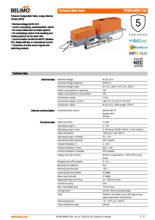
Pressure Independent Valve, 2-way, Internalthread, (EPIV)• Nominal voltage AC/DC 24 V• Control modulating, communicative, Hybrid• For closed chilled and hot water systems• For modulating control of air-handling andheating systems on the water side• Communication via BACnet MS/TP, ModbusRTU, Belimo-MP-Bus or conventional control• Conversion of active sensor signals andswitching contactsTechnical dataElectrical data Nominal voltage AC/DC 24 VNominal voltage frequency50/60 HzNominal voltage range AC 19.2...28.8 V / DC 21.6...28.8 VPower consumption in operation 6 WPower consumption in rest position 5 WTransformer sizing12 VAConnection supply / control cable 3 ft. [1 m], 6 x 0.75 mm²Conductors, cables AC/DC 24 V, cable length <100 m Data bus communication Communicative control BACnet MS/TPModbus RTUMP-BusFunctional data Valve size [mm]2" [50]Operating range Y 2...10 VOperating range Y note 4...20 mA w/ ZG-R01 (500 Ω, 1/4 W resistor)Input impedance100 kΩ (0.1 mA), 500 ΩOperating range Y variable0.5...10 VOperating modes optional VDC variablePosition feedback U 2...10 VPosition feedback U note Max. 1 mAPosition feedback U variable VDC variableSetting Fail-Safe Position NC/NO or adjustable 0...100% (POP rotaryknob)Bridging time (PF) variable0...10 sRunning Time (Motor)90 sRunning time fail-safe<35 sSound power level Motor45 dB(A)Noise level, fail-safe61 dB(A)Adjustable flow rate V'max25...100% of V'nomControl accuracy±5%Min. controllable flow1% of V'nomConfiguration via NFC, Belimo Assistant AppFluid Chilled or hot water, up to 60% glycol max(open loop/steam not allowed)Fluid temperature-10...120°C [14...250°F]Close-off pressure ∆ps200 psi••••Functional dataDifferential Pressure Range 5...50 psi or 1...50 psi see flow reductions chart in tech docFlow characteristic equal percentage or linear Body Pressure Rating 360 psi Leakage rate 0% leakage GPM66Installation position upright to horizontal (in relation to the stem)Servicing maintenance-free Manual overrideexternal push button Measuring data Measured values FlowFlow measurementMeasuring principle Ultrasonic volumetric flow measurement Measuring accuracy flow ±2%Min. flow measurement 0.5% of V'nom Measurement Repeatability ±0.5% (Flow)Sensor TechnologyUltrasonic with glycol and temperature compensation Safety data Degree of protection IEC/EN IP66Degree of protection NEMA/UL NEMA 4EnclosureUL Enclosure Type 4Pressure equipment directive CE according to 2014/68/EU Quality Standard ISO 9001UL 2043 CompliantSuitable for use in air plenums per Section 300.22(C) of the NEC and Section 602 of the IMC Rated impulse voltage supply / control 0.8 kV Ambient humidity Max. 100% RH Ambient temperature -22...122°F [-30...50°C]Storage temperature-40...176°F [-40...80°C]MaterialsValve bodyNickel-plated brass body Flow measuring pipe brass body nickel-plated Valve plug Stainless steel Stem stainless steel Stem seal EPDM (lubricated)Characterized disc TEFZEL®SeatPTFE Pipe connection NPT O-ring EPDM Ballstainless steelTermsAbbreviationsPOP = Power off position / fail-safe position PF = Power fail delay time / bridging timeSafety notesThis device has been designed for use in stationary heating, ventilation and air-conditioning systems and must not be used outside the specified field of application, especially in aircraft or in any other airborne means of transport.Outdoor application: only possible in case that no (sea) water, snow, ice, insolation or aggressive gases interfere directly with the actuator and that is ensured that the ambient conditions remain at any time within the thresholds according to the data sheet.Only authorized specialists may carry out installation. All applicable legal or institutional installation regulations must be complied during installation.The device contains electrical and electronic components and must not be disposed of as household refuse. All locally valid regulations and requirements must be observed.Mode of operationFlow measurement Pre-charging time (start up)Delivery condition (capacitors)Product featuresThe HVAC performance device is comprised of three components: characterized control valve (CCV), measuring pipe with flow sensor and the actuator itself. The adjusted maximum flow (V'max) is assigned to the maximum control signal (typically 100%). The HVAC performance device can be controlled via communicative signals. The fluid is detected by the sensor in the measuring pipe and is applied as the flow value. The measured value is balanced with the setpoint. The actuator corrects the deviation by changing the valve position. The angle of rotation α varies according to the differential pressure through the control element (see flow curves).With the supply voltage the integrated condensors will be charged.Interrupting the supply voltage causes the valve to be moved to the selected fail-safe position by means of stored electrical energy.All flow tolerances are at 68°F [20°C] & water.Flow rate curvesThe capacitor actuators require a pre-charging time. This time is used for charging thecapacitors up to a usable voltage level. This ensures that, in the event of a power failure, the actuator can move at any time from its current position into the preset fail-safe position.The duration of the pre-charging time depends mainly on following factors:– Duration of the power failure – PF delay time (bridging time)Typical pre-charging time[d] = Power failure in days[s] = Pre-charging time in secondsPF[s] = Bridging timeCalculation example: Given a power failure of 3 days and a bridging time (PF) set at 5 s, the actuator requires a pre-charging time of 14 s after the power has been reconnected(see graphic).The actuator is completely discharged after delivery from the factory, which is why the actuator requires approximately 20 s pre-charging time before initial commissioning in order to bring the capacitors up to the required voltage level.Bridging time Setting fail-safe position Power failures can be bridged up to a maximum of 10 s.In the event of a power failure, the actuator will remain stationary in accordance with the set bridging time. If the power failure is greater than the set bridging time, the actuator will move into the selected fail-safe position.The bridging time set at the factory is 2 s. It can be modified on site in operation by means of the Belimo service tool MFT-P.Settings: The rotary knob must not be set to the "PROG FAIL-SAFE" position!For retroactive adjustments of the bridging time with the Belimo service tool MFT-P or with the ZTH EU adjustment and diagnostic device only the values need to be entered.The rotary knob fail-safe position can be used to adjust the desired fail-safe position 0...100% in 10% increments. The rotary knob always refers to the adapted angle-of-rotation range. In the event of a power failure, the actuator will move into the selected fail-safe position. Settings: The rotary knob must be set to the «Tool» position for retroactive settings of the fail-safe position with the Belimo service tool MFT-P. Once the rotary knob is set back to the range 0...100%, the manually set value will have positioning authority.Control characteristics The fluid velocity is measured in the measuring component (sensor electronics) and converted to a flow rate signal.The control signal Y corresponds to the power Q via the exchanger, the volumetric flow isregulated in the EPIV. The control signal Y is converted into a linear characteristic curve andprovided with the V'max value as the new reference variable w. The momentary controldeviation forms the control signal Y1 for the actuator.The specially configured control parameters in connection with the precise flow rate sensorensure a stable quality of control. They are however not suitable for rapid control processes, i.e.for domestic water control. U5 displays the measured flow as voltage (factory setting).Parametrizing V'max with ZTH:U5 refers to the respective V'nom, i.e. if V'max is e.g. 50% of V'nom, then Y = 10 V, U5 = 5 V.Parametrizing V'max with PC-Tool:In the PC-Tool, the maximum flow rate to which U5 refers can be set individually. If V'max ischanged (e.g. to 70% V'nom), the U5 flow range is also automatically changed to the same value(e.g. 70% V'nom: U5 = 10 V). This adjustment can be reversed by entering a value manually (U5flow range = 100%: U5 refers to V'nom).As an alternative, U5 can be used for displaying the valve opening angle.Block diagramCreep flow suppressionConverter for sensorsControl signal inversionHydronic balancing Combination analogue - communicative(hybrid mode)Manual override Flow controlV'nom is the maximum possible flow.V'max is the maximum flow rate which has been set with the highest control signal DDC. V'maxcan be set between 25% and 100% of V'nom.Given the very low flow speed in the opening point, this can no longer be measured by the sensor within the required tolerance. This range is overridden electronically.Opening valveThe valve remains closed until the flow required by the control signal DDC corresponds to 1% of V'nom. The control along the flow characteristic is active after this value has been exceeded. Closing valveThe control along the flow characteristic is active up to the required flow rate of 1% of V'nom. Once the level falls below this value, the flow rate is maintained at 1% of V'nom. If the level falls below the flow rate of 0.5% of V'nom required by the control signal DDC, then the valve willclose.Connection option for a sensor (active or with switching contact). In this way, the analog sensor signal can be easily digitized and transferred to the bus systems BACnet, Modbus or MP-Bus. This can be inverted in cases of control with an analog control signal. The inversion causes the reversal of the standard behavior, i.e. at a control signal of 0%, is equal to V'max, and the valve is closed at a control signal of 100%.With the Belimo tools, the maximum flow rate (equivalent to 100% requirement) can be adjusted on-site, simply and reliably, in a few steps. If the device is integrated in the management system, then the balancing can be handled directly by the management system. With conventional control by means of an analog control signal DDC, BACnet, Modbus, or MP-Bus can be used for the communicative position feedback.Manual control with push-button possible - temporary. The gear train is disengaged and the actuator decoupled for as long as the button is pressed.AccessoriesTools Description TypeConverter Bluetooth / NFC ZIP-BT-NFCWire colors:1 = black 2 = red 3 = white 5 = orange 6 = pink 7 = greyFunctions:C1 = D- = A C2 = D+ = BElectrical installationSupply from isolating transformer.The wiring of the line for BACnet MS/TP / Modbus RTU is to be carried out in accordance with applicable RS485 regulations.Modbus / BACnet: Supply and communication are not galvanically isolated. Connect earth signal of the devices with one another.Modbus RTU / BACnet MS/TP with analogue setpoint (hybrid mode)BACnet MS/TP / Modbus RTUCable colors:1= black 2 = red 3 = white 5 = orange 6 = pink 7 = greyBACnet / Modbus signal assignment:C1 = D– = A C2 = D+ = BConnection with active sensor, e.g. 0...10 V @ 0...50°CPossible voltage range:0...32 V (resolution 30 mV)Connection with switching contact, e.g. Δp monitorRequirements for switching contact:The switching contact must be able to accurately switch a current of 16 mA @ 24 V.Operation on the MP-BusFunctionsFunctions with specific parameters (Parametrisation necessary)Operating controls and indicatorsLED display green On:Device starting upOff:No power supply or wiring error Flashing:In operation (Voltage ok)Flow direction NFC interfaceManual override button Press button:Gear train disengages, motor stops, manual override possible Release button:Gear train engages, standard mode. Device performssynchronisation.Cover, POP button POP buttonScale for manual adjustment Manual override button Press button:Gear train disengages, motor stops, manual override possible Release button:Gear train engages, standard modePush-button (LED yellow)Press button:Acknowledgment of addressingPush-button (LED Green)Press button:Triggers angle of rotation adaptation, followed by standard mode123423456Recommended installation positionsInstallation position in return Water quality requirementsServicing Flow direction Cleaning of pipes Prevention of stressesSetting fail-safe positionSetting emergency setting position (POP)Installation notesThe ball valve can be installed upright to horizontal. The ball valve may not be installed in ahanging position, i.e. with the stem pointing downwards.Installation in the return is recommended.The water quality requirements specified in VDI 2035 must be adhered to.Belimo valves are regulating devices. For the valves to function correctly in the long term, they must be kept free from particle debris (e.g. welding beads during installation work). The installation of a suitable strainer is recommended.Ball valves, rotary actuators and sensors are maintenance-free.Before any service work on the control element is carried out, it is essential to isolate the rotary actuator from the power supply (by unplugging the electrical cable if necessary). Any pumps in the part of the piping system concerned must also be switched off and the appropriate slide valves closed (allow all components to cool down first if necessary and always reduce the system pressure to ambient pressure level).The system must not be returned to service until the ball valve and the rotary actuator have been correctly reassembled in accordance with the instructions and the pipeline has been refilled by professionally trained personnel.The direction of flow, specified by an arrow on the housing, is to be complied with, since otherwise the flow rate will be measured incorrectly.Before installing the valve, the circuit must be thoroughly rinsed to remove impurities. The valve must not be subjected to excessive stress caused by pipes or fittings. EP200+AKRX-E N4 • en-us • 2023-05-24 • Subject to change 11 / 11Inlet section Split installation Behaviour in case of sensor failure In order to achieve the specified measuring accuracy, a flow-calming section or inflow section inthe direction of the flow is to be provided upstream from the flow sensor. Its dimensions shouldbe at least 5x DN.The valve-actuator combination may be mounted separately from the flow sensor. The directionof flow of both components must be observed.General notesIn case of a flow sensor error, the EPIV will switch from flow control to position control.Once the error disappears, the EPIV will switch back to the normal control setting.DimensionsDimensional drawingsTypeWeight EP200+AKRX-E N415 lb [6.7 kg]AB C D E F 26.6" [675]13.9" [353]12.0" [305]10.2" [260] 3.4" [86] 3.4" [86]。
- 1、下载文档前请自行甄别文档内容的完整性,平台不提供额外的编辑、内容补充、找答案等附加服务。
- 2、"仅部分预览"的文档,不可在线预览部分如存在完整性等问题,可反馈申请退款(可完整预览的文档不适用该条件!)。
- 3、如文档侵犯您的权益,请联系客服反馈,我们会尽快为您处理(人工客服工作时间:9:00-18:30)。
ALTO AEX2200双通道听觉激励器概述:AEX2200是新一代的听觉激励器,与过去的激励器相比,AEX2200不仅可以实现人工控制中高频频段的激励和低频段激励,更具有智能化的自动衰减功能,可以利用这个功能衰减在进行激励处理过程中产生的令人不愉快的噪音。
在对音频信号进行激励的同时,还可以利用内部专用的电路处理,实现低频段音乐风格的转变,能满足不同场所对低频的要求。
功能键介绍:前面板1、POWER---电源开关2、BYPASS---直通、接入开关,按下后为直通状态,激励器对输入信号不作任何处理。
3、INPUT LEVEL---输入信号指示灯,指示范围-12分贝到+12分贝,当输入信号过大时,CLIP(削波)指示灯将点亮。
MULTIBAND PROCESSOR(多频段处理器)部分4、SOLO---独奏开关,按下后变为红色,输出的处理后信号中的原始输入信号将被静音,只输出处理后的信号。
5、AUTO REDUCTION---自动衰减处理开关,按下后进入自动处理模式,可以自动进行处理并消除一些不必要的噪声。
不按下这个开关,自动控制部分不对信号进行任何处理,同时所有的效果指示灯将点亮,激励器处于最大处理模式。
6、SENSITIVITY---输入灵敏度控制,转动这个旋钮,可以根据输入信号的强度,对输入信号增益进行控制。
7、EFFECT---效果指示灯,可以实时显示激励器对信号的改变和激励量的大小。
在输入信号处于很低的电平情况下,第一个指示灯仍保持点亮状态。
8、TUNE---频率调谐控制,通过旋转这个旋钮可以调整激励器对于中高频频段的处理范围,也是一个高通滤波器频率调整控制,可以在1kHz---6kHz的范围选择,凡低于选择的频率之下的频带将被切除,不做处理。
9、PROCESS---处理方式控制,通过转动这个旋钮,可以更好的提升高频频段的响度,顺时针旋转为增强方式,逆时针旋转为激励方式,两种方式的不同点在于在提升时的声音的亮度不同,激励方式提升高频的亮度,增强方式提升高频的响度。
10、 HIGH MIX---高频信号混合比调整,这个旋钮用于调整输出信号中原始高频信号和经过提升高频的信号的混合比。
BASS PROCESSOR(低频处理器)部分11、 SHIFT---低频切除开关,通过按下或弹起这个开关切换切除极低频或低频信号。
弹出状态下切除低频信号,按下时切除超低频信号。
12、 LOWMIX---低频信号混合比调整,这个旋钮用于调整输出信号中原始低频信号和经过提升的低频信号的混合比。
13、 MODE---低频增强模式转换开关,有NORMAL(正常)和SOFT(软化)两种状态,弹出时为SOFT状态,可以使比较干的低频效果变成温暖和自然的效果。
SURROUND PROCESSOR(环绕声处理器)部分14、 SURROUND---环绕声处理器功能开关,在输入立体声音源同时双通道处理的情况下,在CHANNL1(通道1)和CHANNL2(通道2)之间进行交叉处理,从而产生环绕声效果。
在不需要做环绕声处理时,保持这个开关处于弹开状态。
15、 SURROUND---环绕声调节旋钮,用于调整两个通道间环绕声处理量,顺时针方向转动可以增强环绕声效果,反之则为立体声效果。
后面板16、电源保险丝17、交流电源输入插座18、 INPUT---信号输入19、 OUTPUT---信号输出连接方法:激励器与系统连接方式一般有两种:链接方式—激励器的输入端连接来自上一级设备的输出端,激励器的输出端连接下一级设备的输入端,一般采用平衡连接方式。
此方式一般用于整体系统声音特性调整。
该方式优点是使用器材少,调整简单;缺点是在进行动态处理时,有可能会对某些特质不同的声音造成影响。
激励器一般在链接环路中安装在均衡器前端。
断点插入方式---利用TRS大三芯立体声插头连接均衡器的输入及输出端,大三芯插头的尖连接均衡器的输入端、大三芯插头的环连接均衡器的输出端、输入输出共用信号地。
将大三芯插头插入调音台输入或输出通道的INSERT(断点插入)插座,即可等于将该激励器介入调音台通道内部。
该方式适用于对单独的输入输出通道进行独立激励处理,一般用于要求特别高的场所。
激励器也可以和效果器一样使用辅助(AUX)连接方式与调音台连接,可以对单独的输入通道的信号进行处理。
一台激励器可以分别进行两种不同的处理方式:采用双单声道输入----双单声道输出方式:从调音台辅助总线输出(AUXOUT1或AUX SEND1)的信号连接至AEX2200后面板的通道1输入(CHANNEL1 INPUT)插口,然后将AEX2200后面板的通道1输出(CHANNEL1 OUTPUT)插口连接到调音台的辅助返回(AUX RETURN1或AUX IN1)插座。
从调音台辅助总线输出(AUX OUT2或AUX SEND2)的信号连接至AEX2200后面板的通道2输入CHANNEL2 INPUT)插口,然后将AEX2200后面板的通道2输出(CHANNEL2 OUTPUT)插口连接到调音台的辅助返回(AUX RETURN2或AUX IN2)插座。
此方式适合一般作为对不同的演唱话筒或乐器以及音源进行的效果处理。
操作方法:步骤一、连通系统,接通电源,弹起激励器各个通道的直通按键(BYPASS)、环绕声开关(SURROUND)和独奏(SOLO)按键,按下超低频切除按键(NORMAL/SOFT),音源设备送出信号,适当推起调音台总音量推杆,检查信号通道是否通畅,系统正常发出声音。
然后进行高频激励处理调节。
步骤二、高频自动处理模式:AEX2200内部装有智能处理电路,可以根据输入信号的性质自动进行激励及增强处理,只需要按下自动衰减开关(AUTO REDUCTION),调整输入灵敏度(SENSITIVITY)旋钮,听音箱发出的声音是否满意,满意后保持灵敏度旋钮的位置即可。
这种方式适合于一般使用场所。
对于要求更高的场所,对于中高频的声音处理一般需要进行人工调节,方法如下步骤三、高频人工调节模式:弹起自动处理开关(AUTO REDUCTION),此时输入灵敏度调节不起作用,把高频信号混合比(HIGH MIX)旋钮逆时针调到最小,处理模式(PROCESS)旋钮逆时针转动放在激励位置(EXCITE)。
信号源信号或话筒信号送出,音箱正常发出声音后,首先顺时针转动高频混合比旋钮(HIGH MIX)到中间位置,这时,注意音箱发出的声音已经开始有所变化;然后转动处理模式旋钮(PROCESS)到中间位置,此时音箱发出的声音应该有明显的改变;然后转动频率调谐旋钮(TUNE),同时听音箱发出的声音,选择需要进行激励的频段,待选定的需要的频段,音箱发出的声音基本满意后,调节处理模式旋钮(PROCESS),可以调整所激励的频段的亮度或者响度,最后,调节高频混合比旋钮(HIGH MIX),增加或衰减经过处理的信号在输出信号中的比例,达到最满意的效果。
然后调整低频激励处理。
步骤四、弹起低频激励模式开关(MODE),使低频处理器处于软化(SOFT)模式,慢慢转动低频混合旋钮(LOW MIX),听音箱发出的低频是否满意。
同时可以切换低频切除开关(SHIFT),选择切除低频部分或超低频部分,这样可以切除一些不必要的低频信号,使低频效果变得更加干净或者更加深沉。
注意:在调节低频混合比旋钮(LOW MIX)时必须小心进行,缓慢转动,防止快速转动该旋钮使激励器产生的极其深沉的低频信号对音箱造成的损害。
步骤五、在一些特殊的使用场所可能需要一些模拟环绕声处理,AEX2200可以提供这样的功能。
首先将设备以链式连接方式安装在系统中,激励器部分按照上面的步骤调节好后,按下环绕声处理器功能开关(SURROUND),调节环绕声处理旋钮(SURROUND)进行环绕声处理。
AEX2200使用技巧在一些相对业余或设备档次不高的场所,利用激励器可以产生立竿见影的效果,能够非常轻松的增加人声的穿透力和系统的层次感以及丰满度。
下面详细叙述各种处理方法:一、人声处理:男声:激励器处于人工操作模式,设置频率调谐旋钮(TUNE)在2.2kHz—3.3kHz 之间,处理旋钮(PROCESS)处于顺时针刻度3格至4格位置,高频混合比(HIGH MIX)旋钮处于中间位置,此时,男声的高频层次感和穿透力得到很大提升。
女声:激励器处于人工操作模式,设置频率调谐旋钮(TUNE)在3.3kHz—4.5kHz 之间,处理旋钮(PROCESS)处于顺时针刻度3格至4格位置,高频混合比(HIGH MIX)旋钮处于中间位置,此时,女声的高频层次感和穿透力得到很大提升。
齿音提升:齿音的提升能够很大程度的消除业余歌手演唱时的疲劳感,使唱歌变得非常轻松。
操作如下:激励器处于人工操作模式,设置频率调谐旋钮(TUNE)在5kHz—6kHz之间,处理旋钮(PROCESS)处于顺时针刻度5格至6格位置,高频混合比(HIGH MIX)旋钮处于中间位置,此时,人声的齿音得到很大提升,声音感觉非常明亮通透。
二、在一些DISCO场所对于音响系统经常要求中高频能提供刺激的声音效果,即所谓“金属声”效果,设置如下:激励器处于人工操作模式,设置频率调谐旋钮(TUNE)在1.5kHz—2.2kHz之间,处理旋钮(PROCESS)处于顺时针刻度5格至6格位置,高频混合比(HIGH MIX)旋钮处于中间位置,此时,系统中高频力度和速度感得到很大提升,声音变得非常“锋利”。
三、在一些演艺场所,对于低频的要求一般要求丰满、深沉,有足够的弥漫感觉,利用AEX2200的低频处理可以制造柔和的低频效果,操作如下:选择低频切除开关(SHIFT)位于按下位置,只切除不必要的次低频,低频混合旋钮转动到2和3位置中间,低频模式(MODE)开关选择SOFT模式。
这样,低频音箱将产生极其深沉丰满的低频效果。
四、在DISCO场所对于低频的要求一般是要具有很强的力度和震撼力,同时还不能缺少弹性,AEX2200可以轻松提供这样的效果。
选择低频切除开关(SHIFT)位于弹起位置,只切除不必要的低频,可以提升低频的速度感和力度感,低频混合旋钮转动到3和4位置中间,低频模式(MODE)开关选择SOFT模式,保证低频的弹性感觉。
这样,低频音箱将发出极其震撼同时弹性十足的低频效果。
注意:超低频音箱配备的功放必须有足够的功率余量(不小于2倍)!防止功放削波失真损坏音箱。
五、很多情况下,受预算影响或其他原因限制,一个音响系统只配备一台激励器的情况下,如何使用一台激励器同时进行两种不同方式的处理,既要对人声进行处理(此时不需要进行低频处理),同时又要对音乐或乐队信号进行全面的处理,激励器连接在主系统中间就无法满足了,要实现这个目标,方法很简单,连接方式如下:将激励器按照上述的连接方法中第三种方法连接到调音台上,和效果器的连接方法相同,等于连接了两台单通道激励器,其中,一个通道用于人声处理,另一个通道进行音乐信号处理即可。