SDS3000使用说明书3.0
Sensotec TensiMaster 3000 产品说明书

Provides the ultimate solution for measuring and monitoring precise tension on web process or wire machinery in demanding industrial environments•For use with pillow block bearingsand rotating shaft installations.•Washdown-duty, withstanding impinging liquids and wet environments.•Designed to comply withNEMA 4x, IP65/67 standards.•Completely sealed. Corrosion-resisting and chemical-resisting (Stainless Steel 410 or Anodized Aluminum Alloy 6061).•Competitively priced againstcommon non-sealed,non-corrosive and chemical resistive designs.•Compact low-profile design fits easily into tight places.•With an end connector design(instead of on the side), no need for a left hand and right hand configuration.•Available in a variety of loadcapacities (25 to 30,000 lb.)and sizes (6.5 to 17 inches long),suiting a wide range of applications.•Provides 500% overload protection.•Easily mounted at any angle.•Convenient mounting plate for easy installation of pillow block bearing.Performance BenefitsThe UPB (Under-Pillow-Block)Washdown-Duty LC (load cell) is part of the Cleveland-Kidder ®Tension Transducer product family. It sets the standard for under-pillow-block tension transducers for the web process industry.The UPB Washdown-Duty LC has a completely sealed corrosion-resisting design, making it ideal for use in demanding industrial environments,including the production of paper, steel,textiles, roofing shingles, linoleum,rubber, foil, and food products.The UPB Washdown-Duty LC can be mounted at any angle. Its web force direction is not restricted to being either parallel or perpendicular to the UPB top surface (common with other load cell designs). Its compact low profile design makes it perfect for use in both retrofit and OEM applications.The UPB Washdown-Duty LC is a solid one-piece design, providing a high natural frequency response with a high level, linear output signal.Design FeaturesThe Cleveland-Kidder UPB Washdown-Duty LC is an under-pillow-block load cell that has been designed formeasuring and monitoring tension on web process and wire machinery in demanding environments.The UPB Washdown-Duty LC is made from a solid block that results in a completely sealed design with a very low profile. It is typically applied in pairs,one under each of the supporting guide roll’s pillow block bearings. Mounting the pillow block bearing to the UPB Washdown-Duty LC is simple and convenient:Rather than having to drill into the top of the load cell, the UPB Washdown-Duty LC uses a convenient mounting plate, making installation andreplacement easier. Held in place by four corner bolts, the mounting plate is easily removed, drilled and tapped to match the pillow block mounting dimensions. The plate is then remounted and the pillow block bearing is bolted into place.To assure maximum corrosion and chemical resistance, the UPBWashdown-Duty LC is made from either Stainless Steel or Aluminum Alloy depending on the size rating.Displacement from loads is negligible (typically 0.002 in.) and the output is temperature compensated.UNDER PILLOW BLOCK WASHDOWN-DUTY LOAD CELLUPB Washdown-DutyLCSIZE RATING (LB) * ULTIMATE OVERLOAD (%)UPB125 to 1000500UPB21000 to 1000050020000250UPB310000 to 30000500INDUSTRIAL PRODUCTSDIMENSION TABLESRATINGSSize Dimensions in Inches*Maximum No.Working Force (lb.)A B C D E F(Max.)G H J(Max.)KL M N WUPB1 1.50.55 5.8 1.55/16(4) 5.8 1.6 1.951/2 1.40 6.5 1.3 2.2 2.2 25, 50, 100, 250, 500, 1000UPB230.8010.0 3.01/2 (4)10.0 3.0 2.473/4 1.6811.0 3.3 3.95 4.01000, 2500, 5000, 10000, 20000UPB3 4.51.6315.04.51 (4)15.6 5.04.21-1/8 2.8017.04.85.26.510000, 20000, 30000Size Dimensions in Millimeters*MaximumNo.Working Force (N)**A B C DE F(Max.)G H J(Max.)KLM N WUPB13814147.538M814740.549.5M1235.5165335656 110, 225, 450, 1100, 2250, 4500UPB2762025476M122547663M2042.5279.584100101.54500, 11000, 22000, 45000, 90000UPB311441.5381114M24396127106.5M307143212213216545000, 90000, 135000Weight lb. (kg.) Each UPB1UPB2UPB33.7 (1.7)22 (10)102 (47)*Ultimate overload: Maximum force applied on the transducer without risking permanentdeformation. For the Washdown duty UPB the output is linear up to the point of the ultimate overload.*Allow 2.5 inches clearance (64mm) for connector.**Approximate rating in Newtons.INDUSTRIAL PRODUCTS SPECIFICATIONSMaterial: Body: Size 1- Anodized Aluminum Alloy 6061Size 2 & 3 Stainless Steel 410Mounting Plates: Stainless Steel 304Bolts for Mounting Plates: Stainless Steel Gage Resistance:Each transducer contains a half-bridge,having a nominal end-to-end resistance of440-480 Ohms.Gage Factor:100 nominalExcitation Voltage:10 VDC or VAC (rms) maximumOutput Signal@ Rated M.W.F.: 100 mV nominal / transducer200 mV nominal / pair(With 10 VDC or VAC rms excitationvoltage)OperatingTemperature Range:0˚F to 200˚FSensitivity Changewith Temp.Less than 0.02% of rated outputtypicalHumidity:95% R.H.CombinedNon-linearityAnd hysteresis:±0.5% maximum of rated output Repeatability:±0.2% maximum of rated output“MS” Connectors:MS-3102E-10SL-3P(Sealed 3 Pin Connector)Input Impedancerequired:5K Ohms per transducer(TransducerSignal Amplifierif not CMCsupplied)Output impedance:880 Ohms for UPB2 and UPB3120 Ohms for UPB1UNDERPILLOWBLOCKWASHDOWN-DUTYLOAD CELLUPBWashdown-DutyLCProcedure for Mounting the UPB Load Cellto the Machine Frame (see picture above)Remove the pillow block mounting plate (it is held in place by four stainless steel corner bolts) in order to gain access to the four load cell mounting holes. Drill and tap the machine frame to match the load cell mounting holes. Note: The UPB must be oriented so that the resultant tension force direction (bisector of the wrap angle) isin the same quadrant as the load direction arrow on the side of the UPB.Bolt the load cell in place. The UPB load cell is designed so that either imperial or metric mounting bolts can be used when mounting the load cell to the machine frame. Refer to E in the Dimensions Table for the proper bolt size. Before remounting the pillow block mounting plate refer to the procedure below.Procedure for Mounting the Pillow Block Bearing to the UPB Load Cell (see picture above)Mounting the pillow block bearing to the UPB is simple and convenient. The UPB is offered with a pillow block mounting plate. The mounting plate is held in place by four stainless steel corner bolts. Remove the mounting plate, then drill and tap it to match the pillow block mounting dimensions. A centerline mark is provided on the mounting plate. The plate is to be drilled and tapped by utilizing this centerline mark to insure that the pillow block bearing is centered on the plate. Remount the plate and bolt the pillow block bearing to it. The mounting plate is 304 Stainless Steel, which is amenable to drilling but offers corrosive and chemical resistance. Refer to Jin the Dimensions Table for the maximum bolt diameterrecommended for bolting the pillow blockbearing to the mounting plate.INDUSTRIAL PRODUCTSUNDER PILLOW BLOCK WASHDOWN-DUTY LOAD CELLUPB LCSIZING CALCULATIONSIZING CALCULATION:ORDERING PROCEDURE:SELECTION CHARTT =Max Tension A =Wrap Angle (Degrees)W =Roll Weight B =Angle of Tension Force (Degrees)K =Overload for Transients(Nominally 1.4 for most applications)MWF = Maximum Working Force(This is used to select the proper force rating of the transducer)C =Mounting Angle H =Bearing Height + DSIZE L (in.) D (in.)UPB1 2.50.98UPB2 4.5 1.25UPB36.52.10A[2KT sin —][HsinB + LcosB] ±W[L cosC – HsinC]**2*The MWF calculation defines the force on each individual load cell.**If Angle B is below horizontal use + in calculation. If Angle B is above horizontal use - in calculation Note: Consult CMC for assistance in sizing the load cell to your specific application.1. Calculate the Maximum Working Force (MWF)rating based upon your calculations from the sizing calculation equation.2. From the Selection Chart,determine the part number for the UPB Washdown-Duty LC. Select a MWF rating that equals or exceeds the MWF from your sizing calculation. Then, make sure that your pillow block bearing fits the UPB type that you selected (UPB 1, 2,or 3).Example: If you calculate a MWF of 2,204 lbs., select a UPB 2 rated at 2,500 lbs.MWF from the Selection Chart. Your part number is M846-12172-100. Then,from the Dimensions Table,make sure that your pillow bearing fits on the Size 2transducer. If it does not,please consult factory.3. Obtain pricing and delivery information by contacting a CMC sales representative,distributor, or the factory.ACCESSORIESACCESSORIES CHART*Load Cell Cable The load cell cable end is provided with a straight or right angle connector as specified. The controller end is provided with tinned leads. The controller end of the cable can be cut to length if the standard length provided is not the exact length required.MWF* =2LTransducer MWF (lbs.)UPB1Rating25501002505001000Part No. M846-12171-000100200300400500UPB2Rating1000250050001000020000Part No. M846-12172-000100200300400UPB3Rating100002000030000Part No. M846-12173-000100200Cable Length Part Number - Straight Connector Part Number - Right Angle Connector 20 Feet MO-01948-020MO-01957-02025 Feet MO-01948-025MO-01957-02550 Feet MO-01948-050MO-01957-05075 Feet MO-01948-075MO-01957-075100 Feet MO-01948-100MO-09157-100150 FeetMO-01948-150MO-01957-150*Cables are not washdown-duty. For washdown-duty cables consult CMC.。
LA3000系列二合一分析仪使用手册说明书

BusFinder系列. LA3000系列二合一分析仪(协议+逻辑)使用手册Publish: 2018/06目录第一章安装与设置 (4)硬件安装 (4)主机外观与功能说明 (4)LA探头 (5)eMMC5.1探头(选配) (6)NAND Flash探头(选配) (7)SD 3.0探头(选配) (8)SD 4.0(uSD 4.0)探头(选配) (9)软件安装 (10)第二章功能列表与操作 (12)协议分析仪 (12)档案 (12)采集 (13)显示波形 (20)搜寻 (20)到末尾 (21)窗口 (21)保存成文本文件 (21)细节窗口 (22)统计窗口 (23)隐藏数据窗口 (23)叠加示波器 (24)光标 (25)逻辑分析仪 (26)档案 (27)采集 (32)采集模式设置 (45)光标 (49)波形区 (52)报告区 (53)总线解碼设置 (54)自定义报告设置 (54)第三章技术支持 (55)附录一探头尺寸规格及脚位定义 (56)LA探头 (56)eMMC5.1探头 (58)NAND Flash探头 (60)SD3.0探头 (61)SD4.0(uSD4.0)探头 (63)附录二Tuning settings (64)第一章安装与设置硬件安装主机外观与功能说明❶插槽(Socket A)❷插槽(Socket B)❸SD 4.0数据传输插孔,此为USB 3.0 Type A 插孔,使用USB 3.0传输线(75cm),仅作为连接SD 4.0转板用,LA3000系列不适用❹指示灯,有2种用途a.绿灯:只有电源与USB传输线都正确接好上电之后,指示灯才会亮起b.红灯:设备正于忙碌中时显示红灯长亮或闪烁❶DC 12V电源插孔❷USB 3.0 Type B传输线插孔,连接计算机用.❸触发输入(Trigger In)插孔❹触发输出(Trigger Out)插孔❺同步参考频率输入(Reference clock)插孔❻同步参考频率输出(Reference clock)插孔探头安装方式推入:将探头持平正对主机插槽,用力平均的将探头推入,听到喀嚓声即安装完成。
SDS3000X系列智能示波器数据手册说明书
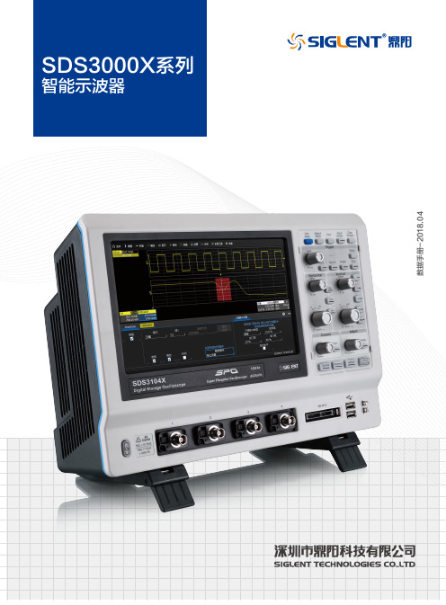
数据手册-2018.04SDS3000X 系列智能示波器数据手册产品综述SDS3000X 系列智能示波器,最大带宽 1GHz,最高实时采样率 4GSa/s,采用创新的 SPO 技术,支持高刷新、256级波形辉度等级及色温显示、数字触发和深存储特性;采用单芯片 ADC,具备优异的模拟前端和信号保真度;支持丰富的智能触发、串行协议触发和解码;支持历史模式(History)、顺序模式(Sequence)、高级波形搜索和分析(WaveScan)、趋势图(Trend)、参数直方图(Histicons)、增强分辨率模式(Eres);具备丰富的测量和数学运算功能;具备独特的综合归档功能(LabNoteBook);支持16路数字通道;集成 25MHz 函数 / 任意波形发生器;配备 Windows 操作系统和10.1 英寸电容触摸屏。
基于以上强大的功能与特性,SDS3000X 可以满足用户日益增长的测试测量和数据分析的需求,是一款性能先进的智能示波器。
特性与优点模拟通道带宽:500MHz、1GHz 4 模拟通道 +1 个外触发通道实时采样率高达 4GSa/s 创新的 SPO 技术 存储深度达 20Mpts/CH 波形捕获率达 1,000,000 帧 / 秒具备优异的模拟前端和信号保真度,最低底噪低于 400μV 支持 256 级波形辉度等级及色温显示配备 Windows 操作系统和 10.1 英寸电容触摸屏(1024*600),支持触摸屏、键盘、 鼠标操作采用顶级的用户界面MAUI,迷人的简洁,所有菜单层级只有两级 集成了 15 种最常用的一键式设计,一触即发智能触发(边沿,脉宽,判定合格,逻辑图,TV,窗口,间隔,漏失,欠幅, 斜率)串行总线触发及解码,支持的协议:I 2C、I 2S、 SPI、 UART/RS232、LIN、CAN、 CAN-FD、 FlexRay、MIL 1553、USB 2.0顺序模式(Sequence),根据用户设置的触发条件,以最小 1us 的死区时 间分段捕获符合条件的事件,并给出时间标签高级波形搜索和分析(WaveScan)功能,支持多种搜索条件,并把捕获的 异常信号用 Zoom 功能展现出来,方便用户在海量信息中快速搜索出需要关 注的波形增强分辨率模式(Eres),通过数字滤波的方式降低噪声带宽,可等效提高 示波器的垂直分辨率,最高可达 11 bit历史模式(History),一键进入,通过导航栏“回放”历史上出现过的波形综合报告归档功能(LabNoteBook), 保存的数据可在示波器和 PC 端进行 再测量和分析24 种参数统计测量和 20 种波形运算,能支持 AIM 测量和波形的运算再运 算(Math on Math)趋势图(Trend),以线图的方式表示参数测量结果随采集的次序变化的过程, 第一次采集的测量结果显示在屏幕的最左边,测量结果从右往左逐渐移动参数直方图(Histicons),反映了参数值在一个确定范围 (Bin) 内出现的概率, 表明了参数值的统计分布状态通过 / 失败(Pass/Fail)检测功能,用户可自定义规则 / 模板,与被测信号 进行比较,实时统计通过 / 失败的次数,可用来查找异常波形或进行自动化测试内置 25MHz 函数 / 任意波形发生器,125MSa/s 采样率,16kpts 波形长度 16 路数字通道(MSO 功能),500MSa/s 采样率,10Mpts 存储深度4 位数字电压表和 5 位硬件频率计功能丰富的外围接口:4*USB Host,SD 卡槽,USB Device,LAN,AUX out (Pass/Fail,Trigger Out),EXT TRIG,标准 D 型 15 针 SVGA 接口(分辨 率 1024*600),16 路逻辑通道接口和可配置的校准信号接口,方便仪器扩 展及程控操作SDS3000X 系列智能示波器数据手册型号与主要指标一键进入运算一键保存一键打印一键清除一键进入历史模式一键调用保存的波形一键复位一键捕获一键放大一键光标一键WaveScan 一键触发点归零同类型500MHzSDS3054XSDS3000X 系列智能示波器数据手册创新的SPO 构架丰富的调试工具包,精确定位问题在实时采样下,SDS3000X 系列最大支持250,000帧/秒的波形捕获率;在顺序模式(Sequence)下,其最高波形捕获率可达1,000,000帧/秒。
盛蒂斯SDS3000主控器4[1].0
![盛蒂斯SDS3000主控器4[1].0](https://img.taocdn.com/s3/m/3916ac1dfad6195f312ba6e7.png)
SDS-3000 Super Lift System Controllers
安全注意事项
安全注意事项不仅适用于主控电脑板,还适用于与主控电脑板配套的其它各种电 子及电气设备。
客户应对收到的货物开箱检查,请仔细确认在运输中是否有破损现象,所收货物 是否与订货要求一致。若发现有遗漏或不相符的情况,请速与供货商联系解决。
5
SDS-3000 Super Lift System Controllers
CN10 CN9 CN8
CN7
CN2 CN1 CN12
6
通讯口2 外呼通讯口
编码器信号
微控制器电源输入
调速器反馈信号
CN6
微控制器控制调速器信号
控制门机
继电器控制 多功能输出1
LCD-DISPLAY-192×64 SDS3000-V-LIFT-CONTROL
SMT 表面贴装技术 SDS-3000系统的各微机线路板都采用SMT 表面贴装技术,结构紧凑,可靠性增 强,性能价格比更高。
高抗干扰设计 主控电脑板采用抗干扰设计,能在较恶劣的环境下连续可靠地工作。主控电脑板 内置开关电源,核心部件均单独供电,供电电压从 DC15V 到 DC24V 均可;硬件 及软件双重“看门狗”,系统意外故障时能够自恢复运行;光耦输入,继电器输 出,主控电脑板与外部环境完全隔离;高性能抗干扰 RS485 通讯器件。
RS485 串行通讯口用于主控电脑板与各远程终端之间的可靠连接。通讯口 1 采集 及输出轿内内选板的信号、采集及输出轿内指令板的信号。通讯口 2 采集及输出 井道中各种信号(外呼板上的信号)。通讯口 3 用于用于两台电梯并联或多台电 梯群控。注意通讯口 3 提供了两种形式的接线端子。通讯口 4 用于同时监控多台 电梯情况下的远程监控,这时需要通过 RS485-232 转接控制板将 RS485 信号转 换成 RS232 信号,再与调制解调器(Modem)相连。
SIGLENT SDS3000X HD 高分辨率数字示波器用户手册说明书
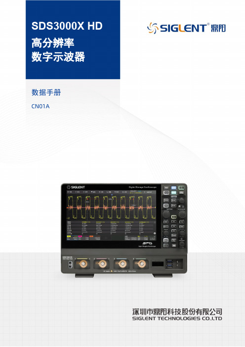
SDS3000X HD数据手册CN01ASDS3104X HDSDS3054X HDSDS3034X HD产品综述SDS3000X HD系列高分辨率数字示波器, 具有最高12-bit 垂直分辨率、优秀的本底噪声性能和垂直测量精度, 能满足更高精度的测量需求。
SDS3000X HD的最大带宽1 GHz, 采样率最高4 GSa/s, 具备4个模拟通道和16个数字通道, 存储深度可达400 Mpts/通道。
SDS3000X HD采用的SPO 技术, 波形捕获率高达890 000帧/秒, 具有256级辉度等级及色温显示;创新的数字触发系统, 触发灵敏度高, 触发抖动小;支持丰富的智能触发、串行总线触发和解码;支持历史 (History)模式、分段采集 (Sequence)、模板测试、搜索、导航、波特图和电源分析等高级分析模式;具备丰富的测量和数学运算功能。
SDS3000X HD采用了10.1 英寸电容式触摸屏, 支持多种手势实现对波形和菜单的常用操作, 结合前面板的多个一键操作按键, 极大地优化了操作示波器的效率, 提升了用户体验。
特性与优点模拟通道带宽:最高1 GHz;实时采样率高达4 GSa/s垂直分辨率:12-bit低本底噪声, 在全带宽下低至125 μVrms高直流增益精度:±0.5%SPO 技术•波形捕获率最高达890 000 帧/秒 (Sequence 模式), 200 000 帧/秒 (正常模式)•支持256 级波形辉度及色温显示•存储深度最高达400 Mpts/通道•数字触发智能触发: 边沿、斜率、脉宽、窗口、欠幅、间隔、超时、码型、第N边沿、建立/保持和视频触发 (支持HDTV)等串行总线触发和解码, 支持的协议包括标配的I2C、SPI、UART、CAN、LIN和选配的CAN FD、I2S、FlexRay、MIL-STD-1553B、SENT、Manchester、ARINC429等分段采集 (Sequence)模式, 最大可以将存储深度等分为80 000 段, 根据用户设置的触发条件, 以非常小的死区时间分段捕获符合条件的事件。
Standard3000中文操作手册part1
Standard3000中⽂操作⼿册part13.6. 電箱/控制器3.6.1. 技術資料y尺⼨(寬×⾧×⾼) 205×340×345 mm3000W y輸出功率 1000/2000/50/60Hz,y電源供應 230V,單相電源y溝通介⾯ RS232y LCD顯⽰螢幕 16⾏×40字y參數資料庫32組焊接參數y加⼯資料庫儲存最近25組焊接資料y重量約16 kg本電箱達到下列⼯業安全規定所需標準:y EN 61000-6-4 EMVy EN 61000-6-2 EMVy EN 55011 class A/group 1y Low voltage guidelines 73/23/ EWG4 操作前注意事項4.1. 連接電源與機器各部分請完成以下步驟使機器準備就緒:1.固定壓機上的⼯作檯2.連接壓機與電箱之間的電線注意:電源線請務必接地。
3.將壓機上之電線插⼊電箱背⾯插座:1壓機2雙⼿起動開關3RF (與換能器連接)4電源4.1.1. 主動溝通裝置5RS232插座 (9孔D-sub插座)6數位輸⼊ (25孔D-sub插座,序列埠)7數位輸出 (25孔D-sub插座,序列埠)其他資料請⾒第⼋章”資料分析”,插座配置請⾒第九章”主動溝通與信號傳送”。
4.1.2. 壓縮空氣源:最⼤7 bar;105 psi依下列指⽰轉動壓縮空氣閥(21):4.將壓縮空氣喉(21a)與壓縮空氣供應源連接。
5.將壓縮空氣閥(21)轉⾄⼯作位置。
注意:若輸⼊壓縮空氣壓⼒⼤於7 bar,附加安全氣閥會⾃動開啟釋放過多的空氣壓⼒。
4.1.3. 裝備隔⾳罩SSK-H1ADG電箱電源2數位輸⼊ (25孔D-sub插座,序列埠) 3數位輸出 (25孔D-sub插座,序列埠) 4壓機5雙⼿起動開關6RF (與換能器連接)拆除隔⾳罩後⽅⾯板可調整壓機,卸除或裝備隔⾳罩。
4.2. 操作及顯⽰元件4.2.1. 壓機1 換能器外罩內藏超⾳波發振系統及電源線。
SDS3000B说明书
注意事项在使用SDS3000B系统前,请务必详细阅读供应商为您提供的相关资料!SDS3000B电源为DC24V,所有的输入端低电平有效。
继电器触点输出时,触点容量为3A,250VAC/3A,30VDC。
当交流负载电压大于36V,直流负载电压大于24V时,请务必在输出端口加以如下的处理:关于接地:进入机房的接地线必须接至控制柜的接地排。
b.对于机房中设备如五线制电源输入的地线、电动机外壳、控制柜外壳,编码器的外壳(若使用时)必须可靠接地,接地点为控制柜的接地排。
c.对于控制柜中设备如变频器、开关电源、变压器必须可靠接地,接地点为控制柜的接地排。
d.对于轿顶设备如门机、轿厢顶部整体必须可靠接地,接地点为控制柜的接地排。
e.对于厅外呼梯盒也应统一接地,接地点为控制柜的接地排。
f.编码器(若使用时)外壳已经接地,但编码器的屏蔽线和外壳相通,此时编码器的屏蔽线另一端(接变频器端)不接地。
g.为了抑制线路间的感应干扰,还应该将变频器的输出动力线和编码器(若使用时)的走线分别导入已经接地的金属管内。
且动力线与信号线距离至少30CM 以上。
前言本资料对SDS3000B系列电梯微机控制器及其辅件在电梯安装、使用、维护等方面进行了系统的阐述。
本手册可作为采用SDS3000B系列电梯微机控制器进行系统设计的参考资料,也可作为系统安装、调试、维护的使用资料;本资料目的,主要讲述了SDS3000B电梯控制系统的安装、调试过程中涉及到的技术问题;详述SDS3000B电梯控制系统的调试过程、调试方法以及故障排除;本资料主要针对广大电梯设计人员,电梯现场配线人员;同时还为电梯维护人员提供相应的技术资料。
本资料面对对象:a.用户b.电梯控制系统设计者c.现场配线调试者d.公司技术支持人员目录第一章.概述 --------------------------------------------- 5 第二章.外型尺寸及端口描述 ------------------------------- 6 第三章.慢车运行 ----------------------------------------- 18 第四章.快车运行 ----------------------------------------- 24 第五章.功能描述 ----------------------------------------- 28 第六章.参数一览表 --------------------------------------- 33 第七章.故障排除 ----------------------------------------- 46 第八章.部分变频器参数设置 ------------------------------- 50第一章 概述SDS3000B系列是电梯控制专用微机控制器,其集成电梯的所有功能,并提供双位七段码显示器,以提示电梯的运行状态和电梯调试时参数设置。
SDS3000使用说明书3.0
高抗干扰设计 主控电脑板采用抗干扰设计,能在较恶劣的环境下连续可靠地工作。主控电脑板 内置开关电源,核心部件均单独供电,供电电压从 DC15V 到 DC24V 均可;硬件 及软件双重“看门狗”,系统意外故障时能够自恢复运行;光耦输入,继电器输 出,主控电脑板与外部环境完全隔离;高性能抗干扰 RS485 通讯器件。
第二章 串行通讯内选板说明
1. 内选控制板概述
内选控制板提供 16 点双向口(输入输出共用端口),每一点对应一层楼的内 选信号,I/O1 接第一站的内选信号,I/O2 接第二站的内选信号,其它依此类推。 内选控制板应通过接点 PE 可靠接地,按钮信号的公共端应接至 24V-,应答灯信 号的公共端应接至 24V+。站数高于 16 站时,需要再加一块内选控制板,注意这 两块内选控制板的软件并不相同,具体情况请向厂家咨询。
电源指示一直亮主cpu工作指示一直闪烁通讯口1通讯指示正常通讯时闪烁操作按键用于状态查询及参数修改enter进入确认键用于进入下一级窗口或设定要修改的参数值esc返回取消键用于返回上一级窗口或取消已修改的参数值up上翻增加键用于菜单间向上翻查或增大要修改的参数值down下翻减少键用于菜单间向下翻查或减小要修改的参数值纽扣电池用于给实时时钟芯片提供电源时钟芯片为系统运行提供时间基准
系统功能在不断的更新,不同的产品功能不尽相同,使用说明书并未将所有系统 功能一一罗列。系统使用了全中文界面,采用的是电梯界通用的术语,用户界面 友好,技术的改进不会对使用造成不便。
SDS-3000系列是一套全电脑控制智能型串行通讯电梯专用控制系统。该系统全面 引进PHILIPS尖端技术,加上公司开发工程师、市场工程师及应用工程师的不懈 努力和超群智慧,将现在及未来的各种需求融入产品之中,充分满足用户的要求。 SDS3000的主要特点是:
施耐德电气 SD3000 PLUS DC 驱动器安装说明书
Installation Instructions SD3000 PLUS DC Drive RegulatorClass 1 LED Product!ATTENTION: Hazard of permanent eye damage exists when using optical transmission equipment. This product emits intense light and invisible radiation. Do not look into module ports or fiber optic cable connectors.!ATTENTION: Energized industrial control equipment can be hazardous. Severe injury or death can result from electrical shock, burn, or unintended actuation of controlled equipment. Hazardous voltages may exist in the cabinet even with the circuit breaker in the off position. Recommended practice is to disconnect and lock out control equipment from power sources, and discharge stored energy in capacitors, if present. If it is necessary to work in the vicinity of energized equipment, the Safety Related Practices of NFPA 70E, “ELECTRICAL SAFETY FOR EMPLOYEE WORKPLACES” must be followed. DO NOT work alone on energized equipment!!ATTENTION: The installation of the drive must be planned such that all cutting, drilling, tapping and welding can be accomplished with the drive removed from the enclosure. The drive is of the open type construction and any metal debris must be kept from falling into the drive. Metal debris or other foreign matter may become lodged in the drive circuitry resulting in component damage.!ATTENTION: An incorrectly applied or installed drive can result in component damage or a reduction in product life. Wiring or application errors, such as, undersizing the motor, incorrect or inadequate AC supply, or excessive ambient temperatures may result in malfunction of the system.!ATTENTION: Only qualified personnel familiar with DC drives and associated machinery should plan or implement the installation, start-up and subsequent maintenance of the system. Failure to comply may result in personal injury and/or equipment damage.2SD3000 PLUS DC Drive RegulatorMinimum Mounting ClearancesMount the SD3000 PLUS in a clean, dry location. Contamination from oils, corrosive vapors and abrasive debris must be kept out of the enclosure.•Do not mount heat-generating equipment underneath the unit •Mount the unit in a vertical position onlyOperating TemperaturesThe surrounding air temperature must be within 0 °C to 50 °C (32 °F to 122 °F).!ATTENTION: This drive regulator contains ESD (Electrostatic Discharge) sensitive parts and assemblies. Static controlprecautions are required when installing, testing, servicing or repairing this assembly. Component damage may result if ESD control procedures are not followed. If you are not familiar with static control procedures, reference A-B publication 8000-4.5.2, “Guarding Against Electrostatic Damage” or any other applicable ESD protection handbook.SD3000 PLUS DC Drive Regulator3 DimensionsDimensions are in inches and (millimeters).Weight kg (lbs.)Drive Regulator Drive Regulator & Packaging7.03 (15.5)7.71 (17.0)Important:Allow at least 4.5 inches (114.3 mm) for connectors and cablebend radius in front of unit.4SD3000 PLUS DC Drive RegulatorConnecting Power Wiring and GroundingTable 1.A Terminal SpecificationsDescription Part Number for Customer Plug (provided with SD3000 PLUS)Wire Size Range TorqueMaximum Minimum Recommended Input Power Terminal Block L1, L2, Ground Input power 94809302 4.0 mm 2(10 AWG) 2.5 mm 2(14 AWG)0.677909 N-m (6 lb.-in.)Ground StudChassis GroundUse grounding cable kit 97297501 provided with regulatorExternal Gate Power Supply External Gate Power Supply (if used)9480930110 AWG, Twisted Pair, 2 Twists / in.18 AWG, Twisted Pair, 2 Twists / in.0.677909 N-m (6 lb.-in.)Meter PortsMeter Port Output 49455-115H14 AWG,Twisted Pair, 2 Twists / in. 13feet (4m) max. length22 AWG,Twisted Pair, 2 Twists / in. 13feet (4m) max. length0.677909 N-m (6 lb.-in.)1234SD3000 PLUS DC Drive Regulator 5Connecting Control WiringClass 1 LED Product!ATTENTION: Hazard of permanent eye damage exists when using optical transmission equipment. This product emits intense light and invisible radiation. Do not look into module ports or fiber optic cable connectors.No.DescriptionConnects toUse Cable NumberXMIT – Fiber optic transmit portThe Drive Comm receive port on the 1756-DMD30, ControlLogix Drive Module •1756-DMCF001 – 1 meter Drive Comm cable •1756-DMCF003 – 3 meter Drive Comm cable •1756-DMCF010 – 10 meter Drive Comm cable •1756-DMCF030 – 30 meter Drive Comm cable •1756-DMAF - adapter for existing UDC/PMI cableRCV - Fiber optic receive portThe Drive Comm transmit port on the 1756-DMD30, ControlLogix Drive Module METER PORTS – Four analog outputs for the monitor of internal registers Analog meters or analog inputs of a monitoring device14-22 AWG, twisted pair, 2 twists per inch.ARM FDBK – Voltage, Current and Phasing feedbackScaling Module, Current Transformers and Phasing TransformerCbl, Arm Fdbk/Pwr_Mod•SD3K-CBLSCLR048 – 4 foot length •SD3K-CBLSCLR060 – 5 foot length •SD3K-CBLSCLR096 – 8 foot length (97305800 to view drawing for additional lengths)FIELD – Field Gate signals and Current FeedbackField Power Module Cable,Fld Gate/Fdbk•SD3K-CBLFLD060 – 5 foot length(97306200 to view drawing for additional lengths)RESOLVER FEEDBACK – Resolver and One input for analog feedback (analog tachometer, if used or other analog signal)Resolver, Analog Tachometer or other Analog source Cable,Rslvr/Anlg, DIN TB •SD3K-CBLRSLVR060 – 5 foot length •SD3K-CBLRSLVR096 – 8 foot length (97305600 to view drawing for additional lengths)1234566SD3000 PLUS DC Drive RegulatorNote : Refer to part drawing for additional cable lengths.DRIVE I/O – 120VAC Drive Command / Control Inputs•RPI – Run Permissive Input•MCR – Output to control M Contactor •Auxiliary Input 1 – M Contactor feedback •Auxiliary Input 2 – Inverting fault circuit breaker (if circuit breaker is used)•Auxiliary Input 3 – Power module thermal interlock•Auxiliary Input 4 – Motor thermal switch •Auxiliary Input 5 – (spare)Cable, Drive I/O, DIN TB•SD3K-CBLDRVIO060 – 5 foot length •SD3K-CBLDRVIO096 – 8 foot length (97305700 to view drawing for additional lengths)EXT GATE P/S – External Gate Power SupplyExternal Gate 48V Power SupplyContact Development for interlocking guidelines18 AWG minimum, twisted pair, 2 twists per inchFWD GATES – Armature Forward Gates Four forward gate outputs to provide gatesignals for up to four power modulesAll four outputs are identicalCable, “Round Style” Connector, Fwd Gates •SD3K-CBLFWDPM060 – 5 foot length •SD3K-CBLFWDPM120 – 10 foot length •SD3K-CBLFWDPM180 – 15 foot length •SD3K-CBLFWDPM240 – 20 foot length (97305100 to view drawing for additional lengths)REV GATES - Armature Reverse GatesFour reverse gate outputs to provide gate signals for up to four power modules. All four outputs are identicalCable, “Round Style” Connector, Rev Gates •SD3K-CBLREVPM060 – 5 foot length •SD3K-CBLREVPM120 – 10 foot length •SD3K-CBLREVPM180 – 15 foot length •SD3K-CBLREVPM240 – 20 foot length (97305300 to view drawing for additional lengths)120VAC – Power input to regulator Cabinet control power10-14 AWGNo.DescriptionConnects toUse Cable Number 7891011SD3000 PLUS DC Drive Regulator7 Checking the IndicatorsLED IndicatesGP Gate Power is presentLP Logic Power is presentOK The drive regulator has passed its internal power-up diagnostic tests. Afterpower-up this LED will turn off if the internal “watchdog timer” fault occurs.P.M. FLT Shorted SCR, Field Current Feedback too low or too high.EXT. FLT Loss of AC Line Synchronization, AC Line Missing, Instantaneous Over-Current(IOC), Over-speed, User program has initiated the illumination of the LED.COMM OK Drive Comm is active and synchronized.FDBK OK The SD3000 Plus is receiving feedback from the resolver and no resolver feedbackfaults have been detected. If the LED is off, one of the following faults may haveoccurred:•Feedback Loss Fault - armature voltage has exceeded 40% of the rated valueand speed feedback has been less than 5% of motor base speed•Broken Wire Fault - a resolver sine or cosine signal is missingRPI The Run Permissive Input (RPI) is energized.AUX IN 1Auxiliary Input 1 is energized. This input usually indicates the status of theM-Contactor.AUX IN 2Auxiliary Input 2 is energized. This input often indicates the status of an invertingfault circuit breaker.AUX IN 3Auxiliary Input 3 is energized. This input often indicates the status of the PowerModule’s airflow switch.AUX IN 4Auxiliary Input 4 is energized. This input often indicates the status of the motorthermal switch.AUX IN 5Auxiliary Input 5 is energized.AUX OUT Auxiliary Output is energized.8SD3000 PLUS DC Drive RegulatorRelated Products and DocumentationAllen-Bradley and Reliance Electric publications are available on the internet at /literature .Specifications ElectricalControl Input 120V ac ±10%, 2.2A, 47-63 HzReplacement fuseLittelfuse 312007, 7Amp, 250 V ac, 3AG or equivalent.EnvironmentalOperating Temperature 0 C to 50 C (32 F to 122 F)Storage Temperature -40 C to 70 C (-40 F to 158 F)Relative Humidity5% to 95%, Non-condensingGate Hardware OverviewCatalog number:Document title:Pub. number:1756-DM ControlLogix Drive Module Installation Instructions 1756-IN577…1756-DM ControlLogix Drive Module User Manual (All Types)1756-UM522…1756-DMD30Reference Manual - ControlLogix Drive Module (SD3000 Interface)1756-RM088…SD3000 PLUS DC Drive Regulator9Note: Dierikon power module gate coupling boards are compatible with the SD3000 Plus.Publication DSSD3P-IN001C-EN-P - November 2005Supersedes DSSD3P-IN001B-EN-P - December 2004Copyright © 2005 Rockwell Automation. All rights reserved. Printed in the U.S.A.。
德瑞斯3000系列变频器说明书
DRS3000系列使用手册 概述第一章 概述1.1开箱检查从包装箱取岀变频器检查产品外壳是否损坏变形, 元件是否有损坏、脱落, 必要时,用工具检查一下;观察机箱侧面铭牌的额定值,认真核查该产品是否与您的订货要求一致; 装箱单内所列物品是否齐全;若有疑问或产品岀现损坏,请立即与供货商联系解决。
1.2变频器型号说明DRS3000-V4T0110C变频器系列号变频器类型代号 矢量通用型 v .矢量注塑机型Z 电压等级 代号 220V 2 - 380V4_表示变频器无内置制动单元和制动电阻。
变频器为标准型时, A 省略不写B 表示变频器有内置制动单元和制动电阻。
C 表示变频器有内置制动单元,但无制动电阻。
图1-1变频器型号说明电压相数 代号 三相 T单相S适配电机功率代号 11kW 0110概述DRS3000系列使用手册1.3变频器铭牌说明在变频器箱体的右侧板下方,贴有标示变频器型号及额定值的铭牌, 铭牌内容如图1-2所示。
MODEL: DRS3000-V4T0110C POWER: 11KWINPUT: 3PH 380VAC 50Hz OUTPUT: 17KVA 25A 0-400Hz. _______ INO.:iiiiiiiiiiiiiiiiiiiiiiiiiiiiniiir30V0110006217 —二dir iseDIRISE ELECTRICS TECHNOLOGY CO.,LTD图1-2变频器铭牌1.4变频器各部位名称说明控制端子面盖固定插入孔 屏蔽板键盘连接端口输出电缆 主回路端子 主回路出口控制电缆入口固定基板箱体安装孔变频器型号~适配电机功率输人电压等级 及频率输出视在功率、 电流及频率 产品序列号上面盖控制键盘变频器铭牌下面盖安装孔下面盖通风孔图1-3 DRS3000-V4T0055C 以上变频器部件名称1.5变频器系列型号说明1装1.6.1操作键盘的拆卸和安装(如图1-4所示) 1、拆卸:将中指或食指放入操作键盘上方的手指插入孔,压住顶部弹片之后往外拉,即可卸下键盘。
- 1、下载文档前请自行甄别文档内容的完整性,平台不提供额外的编辑、内容补充、找答案等附加服务。
- 2、"仅部分预览"的文档,不可在线预览部分如存在完整性等问题,可反馈申请退款(可完整预览的文档不适用该条件!)。
- 3、如文档侵犯您的权益,请联系客服反馈,我们会尽快为您处理(人工客服工作时间:9:00-18:30)。
SDS-3000系列是一套全电脑控制智能型串行通讯电梯专用控制系统。该系统全面 引进PHILIPS尖端技术,加上公司开发工程师、市场工程师及应用工程师的不懈 努力和超群智慧,将现在及未来的各种需求融入产品之中,充分满足用户的要求。 SDS3000的主要特点是:
电源指示(一直亮) 主 CPU 工作指示(一直闪烁) 通讯口 1 通讯指示(正常通讯时闪烁)
操作按键用于状态查询及参数修改
ENTER 进入(确认)键,用于进入下一级窗口或设定要修改的参数值
ESC
返回(取消)键,用于返回上一级窗口或取消已修改的参数值
UP
上翻(增加)键,用于菜单间向上翻查或增大要修改的参数值
1
SDS-3000 Super Lift System Controllers
并联群控及远程监控系统 SDS-3000采用先进的群控调配原则,使群控可靠,调配合理,大大提高电梯的运 行效率。 SDS-3000系统有远程监控功能,可远程监控电梯运行。同一幢大楼里面只需一根 电话线,便可同时监控大楼里的最多八台电梯。监控系统界面友好,功能强大, 大大减少电梯维护保养的工作量。 操作功能强大,灵活而又实用 SDS-3000系统操作功能丰富、先进、合理,全能而又人性化的人机操作界面,现 场配置极为灵活,电梯调试直观简易。全中文液晶显示操作面板,不仅能显示电 梯运行状态和运行记录,还能实时显示电梯的运行故障信息,电梯状态一目了然。 合理的全中文树形目录菜单,方便参数查看及设置。详细的历史故障记录,是电 梯维护及电梯运行状况分析的好帮手。 适用范围宽广 SDS-3000系统适用范围广,其主控电脑板可适用不同层站、不同速度、不同功能 要求的电梯。标准变频器配置包括艾默生、科比、米高、安川、富士以及其它所 有在控制方式上与上述六种变频器兼容的变频器。可以配增量(普通)编码器和 绝对值编码器(德国海得汉绝对值编码器或与之兼容的产品)。
PE
CN3
+24V A1 B1 0V
7
SDS-3000 Super Lift System Controllers
第三章 串行通讯外呼板说明
1. 外呼板地址设定
外呼板地址设定采用一个五位的拨码开关,地址设定用二进制表示,第一位 拨码开关为二进制地址的最低位,第五位拨码开关为二进制地址的最高位。地址 设定均以站(绝对楼层)来表示。当地址设为零时,外呼板便可挂接在轿厢内作 为轿内层显板。
5
SDS-3000 Super Lift System Controllers
CN10 CN9 CN8
CN7
CN2 CN1 CN12
6
通讯口2 外呼通讯口
编码器信号
微控制器电源输入
调速器反馈信号
CN6
微控制器控制调速器信号
控制门机
继电器控制 多功能输出1
LCD-DISPLAY-192×64 SDS3000-V-LIFT-CONTROL
DOWN 下翻(减少)键,用于菜单间向下翻查或减小要修改的参数值
纽扣电池用于给实时时钟芯片提供电源,时钟芯片为系统运行提供时间基准。时 钟芯片供电电压限定在 1.0V-5.5V 范围内。按相关资料计算,纽扣电池使用寿命 为 20 年。电池实际使用寿命会受到制造时实际容量及工作环境的影响。电池电 量不足时应及时更换,电池额定电压为 3.3 伏。
危险
以下情况应该加以严重注意,没有按要求操作,可能造成设备严重损坏或人员伤 亡。
危险1:应由合格的电气工程人员进行接线作业,接线前请确认主控电脑板供电 电源处于关闭状态。否则有损坏电路板和引起火灾的危险。 危险2:请勿对主控电脑板进行耐压试验,耐压试验只在产品出厂前进行,否则 有损坏电路板的危险。请确保主控电脑板供电电源的正负极未接反,且供电电压 符合设计要求,否则有损坏电路板的危险。 危险3:在电梯安全回路信号及各安全装置完全有效的情况下,才允许电梯运行, 否则有物品损坏及人员伤亡的危险。
注意
以下情况应该加以注意,没有按要求操作,可能会造成中等程度伤害或轻伤,或 造成物质损害和财产损失:
注意1:搬运时,应轻拿轻放,否则有损坏控制器的危险。请不要用手触及控制 器的元器件,否则有静电损坏的危险。请不要用潮湿的手触及控制器,否则有损 坏控制器的危险。 注意2:请安装在金属等不可燃物上,否则有发生火灾的危险。不要安装在含有 爆炸气体、油雾、高温及可能产生水滴飞溅的环境中,否则有发生火灾及损坏控 制器的危险。
继电器控制 多功能输出2
通讯口3 并联及群控口
通讯口1 轿厢内选通讯口
ENTER
UP
DOWN
ESC
微控制器输入信号
微控制器输入信号
微控制器输入信号
通讯口4 远程监控口
CN5
CN4
CN3 CN11
SDS3000-V主控器结构及尺寸示意图
SDS-3000 Super Lift System Controllers
SDS-3000 Super Lift System Controllers
SDS-3000 Super Lift System Controllers
前言
非常感谢使用SDS3000系列产品,本说明书叙述了SDS3000系列产品的安装、调 试、维护方面的内容。在使用本产品前,请谨慎认真阅读本说明书,特别是有关 安全注意事项。在全面了解本产品的性能特点后,才可以使用本产品。
第二章 串行通讯内选板说明
1. 内选控制板概述
内选控制板提供 16 点双向口(输入输出共用端口),每一点对应一层楼的内 选信号,I/O1 接第一站的内选信号,I/O2 接第二站的内选信号,其它依此类推。 内选控制板应通过接点 PE 可靠接地,按钮信号的公共端应接至 24V-,应答灯信 号的公共端应接至 24V+。站数高于 16 站时,需要再加一块内选控制板,注意这 两块内选控制板的软件并不相同,具体情况请向厂家咨询。
RS485 串行通讯口用于主控电脑板与各远程终端之间的可靠连接。通讯口 1 采集 及输出轿内内选板的信号、采集及输出轿内指令板的信号。通讯口 2 采集及输出 井道中各种信号(外呼板上的信号)。通讯口 3 用于用于两台电梯并联或多台电 梯群控。注意通讯口 3 提供了两种形式的接线端子。通讯口 4 用于同时监控多台 电梯情况下的远程监控,这时需要通过 RS485-232 转接控制板将 RS485 信号转 换成 RS232 信号,再与调制解调器(Modem)相连。
2. 外呼板显示
系统标准配置的外呼板是采用串行通讯方式,滚动式点阵显示楼层及运行方 向。
在外呼板刚上电时,若地址设为零,则显示字符‘C’,表示该外呼板可放在 轿内作层显用,若地址设为一个二进制值,则显示字符‘F x’,如设为地址 3, 则显示‘F 3’,表示该外呼板放在第 3 站作外呼板用。外呼板上电几秒钟后,转 为正常显示,若没有通讯,外呼显示将自行熄灭。正常运行时,外呼板显示当前 楼层(实际楼层)和运行方向。电梯出现故障时,外呼板以闪烁形式交替显示故 障号及当前楼层。如 3 号故障显示为闪烁的“E 3”字样。当同时有多个故障信号 出现时,故障号最小的故障优先显示。故障含义如下:
高效可靠的运行控制 系统采用两片高速CPU来协调处理电梯运行数据,并以最短响应时间控制电梯运 行。远程终端实时采集轿厢及井道信号,通过RS485串行通讯传输至主控电脑板 集中处理,从而获得高效可靠的运行控制。
RS485 总线串行通讯 采用目前国际上流行的高抗干扰设计的RS485总线进行各部件之间的串行数据交 换,使用极少连接线,便能实现各部件之间高速、可靠地传输数据。不仅大幅度 减少了生产、安装和调试的工作量,还提高了整机的可靠性。
SMT 表面贴装技术 SDS-3000系统的各微机线路板都采用SMT 表面贴装技术,结构紧凑,可靠性增 强,性能价格比更高。
高抗干扰设计 主控电脑板采用抗干扰设计,能在较恶劣的环境下连续可靠地工作。主控电脑板 内置开关电源,核心部件均单独供电,供电电压从 DC15V 到 DC24V 均可;硬件 及软件双重“看门狗”,系统意外故障时能够自恢复运行;光耦输入,继电器输 出,主控电脑板与外部环境完全隔离;高性能抗干扰 RS485 通讯器件。
2
SDS-3000 Super Lift System Controllers
安全注意事项
安全注意事项不仅适用于主控电脑板,还适用于与主控电脑板配套的其它各种电 子及电气设备。
客户应对收到的货物开箱检查,请仔细确认在运输中是否有破损现象,所收货物 是否与订货要求一致。若发现有遗漏或不相符的情况,请速与供货商联系解决。
3
SDS-3000 Super Lift System Controllers
4
SDS-3000 Super Lift System Controllers
第一章 主控电脑板说明
1. SDS3000-V 型主控电脑板概述
SDS3000-V 型主控电脑板为单块电路板结构。 SDS3000-V 型主控电脑板包含 64*196 点阵蓝屏液晶显示一块,4 个操作按键,32 点共阳输入点,14 点继电器输出点,4 个 RS485 串行通讯口(通讯口 1、2、3、 4)及 3 个一列的指示灯和 1 粒钮扣电池。 3 个一列的指示灯,由上到下依次为:
SDS3000 系列 控制系统说明 电梯调试维护
使用说明
2005.9
与此产品有关的电梯设计、安装、调试、维保及技术支持人员应仔细阅读该说明书, 并请妥善保存,以备后用
SDS-3000 Super Lift System Controllers
SDS-3000 Super Lift System Controllers
第一章 主控电脑板说明…………………………………………5 第二章 串行通讯内选板说明……………………………………7 第三章 串行通讯外呼板说明……………………………………8 第四章 控制系统说明……………………………………………10 2 输入输出信号、基本连接 第五章 输入信号…………………………………………………13 第六章 输出信号…………………………………………………19 第七章 基本连接…………………………………………………23 3 系统功能 第八章 功能详述…………………………………………………26 第九章 中文液晶显示及参数设置方法…………………………32 第十章 参数表……………………………………………………38 第十一章 参数详述………………………………………………46 4 系统调试 第十二章 慢车调试………………………………………………51 第十三章 快车调试………………………………………………54 5 系统与变频器的接口 第十四章 配艾默生变频器………………………………………56 第十五章 配科比变频器…………………………………………59 第十六章 配米高变频器…………………………………………65 第十七章 配安川变频器…………………………………………69 第十八章 配富士变频器…………………………………………75 6 维护参考 第十九章 故障或提示信息………………………………………82