SCYG310高频动态压力传感器
sc0073

SC0073 微型动态脉搏微压传感器动态微压传感器是一种高性能、低成本的压电式小型压力传感器,产品采用压电薄膜作为换能材料,动态压力信号通过薄膜变成电荷量,在经传感器内部放大电路转换成电压输出。
该传感器具有灵敏度高,抗过载及冲击波能力强,抗干扰性好、操作简便、体积小、重量轻、成本低等特点,广泛应用于医疗、工业控制、交通、安全防卫等领域。
通过测试该型号传感器性能基本满足条件,但是信号稳定性欠佳,尤其是柱状的结构外形,导致其无法与腕带方便的配合。
●典型应用:脉搏计数探测按键键盘,触摸键盘振动、冲击、碰撞报警振动加速度测量管道压力波动其它机电转换、动态力检测等●动态微压传感器主要性能指标:压力范围:≤1Kpa灵敏度:≥0.2mv/pa非线性度:≤1% F.S频率响应: 1~1000HZ标准工作电压: 3V (DC)扩充工作电压: 1.5~6V (DC)标准负载电阻: 10K扩充电阻: 5K~20K外形尺寸: F12.7 X 7.6重量:<1.5g产品价格: SC0073 60元/只前置放大电路对于脉搏波信号采集来说至关重要,考虑到脉搏信号的特点,为了放大噪声环境中传感器输出的弱信号,对于放大器要求具有:极高的共模和差模输入阻抗;很低的输出阻抗;精确和稳定的增益;极高的共模抑制比。
基于以上分析,选用ANALOG DEVICES公司生产的低功耗、高精度仪表放大器AD620作为前置放大的核心器件。
图3是AD620的简化示意图,AD620由三个放大器组成,其内部采用“三运算放大器”典型电路,仅需要一只外接电阻便可使增益在1~1 000之间任意调节,其调节是通过1脚和8脚间的阻抗Rg来实现的。
AD620管脚图如图4所示。
前置放大电路结构如图5所示。
正常人安静时的心率,成年男性约为60--80次/min;女性约为70--90次/min;入睡状态时心率减少,男性为50--70次;女性为60--70次min;有的人可低达45--50次/min;婴儿为120--140次/min;1--2岁为110次左右/min;3--4岁为90--100次/min;5--6岁为95次左右/min;7--8岁为85次左右/min;9--15岁为70--80次/min;小儿在熟睡时心率可减慢10--40次/min;站立、运动、饭后、情绪变化以及某些疾病时心率可增快。
MICROTEC CA310多功能传感器说明书

Housing: swivelling (30°)Material: ABS V0 as per UL94Protection: IP63Cable gland: in polyamide for cables Ø8 mm maximum Fitting: barbed fittings Ø6.2 mm Weight: 1150 gKEY POINTS●1 input for interchangeable probe●1 location for SPI-2 or MVA interchangeable board●Alternating display of 1 to 3 parameters ●3 audible and visual (dual-color LEDs) alarms ●3 analogue outputs (4 wires) 0/5-10 V or 0/4-20 mA●3 reverse relays 3 A/230 Vac●24 Vdc/Vac or 115/230 Vac power supply●Outputs diagnostic●Ethernet communication (optional)●MODBUS network RS485 system (optional)●ABS V0 swivelling housing ●Large display: 50 x 190 mmFEA TURES OF THE HOUSINGTECHNICAL SPECIFICATIONSPART NUMBERSCA310-B : multifunction transmitter, 24 Vac power supplyCA310-H : multifunction transmitter, 115-230 Vac power supplyPower supply24 Vac / Vdc ±10%100-240 Vac, 50-60 HzWarning: risk of electric shockOutput3 x 0/4-20 mA or 3 x 0-5/10 V (4 wires)Common mode voltage <30 VACMaximum load: 500 Ohms (0/4-20 mA) / Minimum load: 1 K Ohms (0-5/10 V)Galvanic isolationOn the outputsDevice fully protected by DOUBLE ISOLATION or REINFORCED ISOLATION Consumption with probe and without option CA310-B: 11 VA CA310-H: 16 VA(CO 2 probe additional consumption for 24 V and 115-230 V models: 2 VA)Relays 3 reverse relays 5 A / 230 Vac Audible alarm Buzzer (70 dB at 10 cm)European directives 2014/30/EU EMC; 2014/35/EU Low Voltage; 2011/65/EU RoHS II; 2012/19/EU WEEE Electrical connectionScrew terminal block for cables from 0.05 to 2.5 mm 2 or de 30 à 14 AWG Carried out according to the code of good practiceRS485 communication (optional)Digital: Modbus RTU protocol, configurable communication speed from 2400 to 115200 BaudsEthernet communication (optional)Ethernet communication module allowing transmission, monitoring and maintenance of transmitters via an Ethernet network in 10 BASE-T and 100 BASE-TX LAN/WAN supporting TCP/IP protocol(additional consumption for 24 V and 115-230 V models: 1 VA)240 mm60.5 mm120 m m25 m mCA 310Large display multifunction transmitterEnvironment and type of fluid Air and neutral gasesConditions of use (°C/%RH/m)From -10 to +50°C. In non-condensing condition. From 0 to 2000 m Storage temperature From -10 to +70°CSecurityProtection class 2; Pollution degree 2; Overvoltage category 2TECHNICAL SPECIFICA TIONSRELA YS AND ALARMSCA310 transmitter has 3 independent and configurable alarms : these are visual and audible alarms and it is possible to couple them with 3 relays.Available settings:●Selection of the parameter (pressure, air velocity, temperature,...)●Time-delays durations from 0 to 600 s ●Alarm action: rising edge, falling edge, monitoring or state of the transmitter ●Operating mode of the relays: negative or positive safety ●Activation of the audible alarm (buzzer), that can be acknowledge by the front keypadCONNECTIONSCable glandsPressure connections(optional)Power supply terminal block (c)LCC-S software connection Solenoid valve Analogue output (a)0/4-20 m A – C u r r e n t0-5/10 V – V o l t a g eG N D – G r o u n d Analogue output 1 (OUT1)G N D – G r o u n d Analogue output 2(OUT2)(a)AutozeroEthernet connection (optional)Type of power supply of the transmitterProbe connection0/4-20 m A – C u r r e n t0-5/10 V – V o l t a g eRS 485 connection (d) (optional)0/4-20 m A – C u r r e n t0-5/10 V – V o l t a g eG N D – G r o u n d Analogue output 3(OUT3)For 24 Vdc/Vac power supply models:For 115 Vac to 230 Vac power supply models:or(c)(c)N e u t r a l (N )~P h a s e (L )~O p e r a t i o n a l g r o u n d i n gN e u t r a l (N ) -P h a s e (L ) +O p e r a t i o n a l g r o u n d i n gSPI-2 board (optional)N O : N o r m a l l y o p e n N C : N o r m a l l y c l o s e dRelay 1C O M : C o m m o n N O : N o r m a l l y o p e n N C : N o r m a l l y c l o s e dRelay 2C O M : C o m m o n (b)A +B-Modbus:123(d)GND N O : N o r m a l l y o p e n N C : N o r m a l l y c l o s e dRelay 3C O M : C o m m o n Relays (b)ELECTRICAL CONNECTIONS – as perNFC15-100 NormThis connection must be made by a formed and qualified technician. Whilst making the connection, the transmitter must not be energized.The presence of a switch or a circuit breaker upstream the device is compulsory.➢0/4-20 mA current output connection:0/4-20 mA Regulator display orPLC/BMS passive type ➢0-5/10 V voltage output connection:➢For 115 Vac to 230 Vac power supply models:+-24 Vdc power supply +-➢For 24 Vdc power supply model:24 Vac power supplyN LLN Pe 230 VacLN Pe 230 Vacor24 Vac power supplyClass IILN LN LN 24 VacLN115/230 Vac power supply0-5/10 VGND-+Regulator display orPLC/BMS passive type-+0/4-20 mA 0-5/10 VGNDL N 24 Vac➢For 24 Vac power supply model:POSSIBLE OPTIONAL MEASUREMENTSThe following probes and boards are available as option for C310 transmitters. For further details please see the technical datasheet of probes for class 310 transmitters.ProbesMeasuring rangesStainless steel or polycarbonate hygrometry / temperature probe From 0 to 100%RH and from -40 to +180°C (according to probe)Air velocity vane probe: air velocity / temperature / airflow From -5 to 35 m/s (according to probe) / From -20 to +80°C / From 0 to 99 999 m³/h Air velocity hotwire probe: air velocity / temperature / airflow From 0 to 30 m/s / From -20 to +80°C / from 0 to 99 999 m³/h Omnidirectional probe: air velocity / temperature From 0 to 5 m/s and from 0 to 50°C Pt100 1/3 DIN temperature probe From -50 to +180°C / From -20 to +80°C CO / temperature probe From 0 to 500 ppm and from 0 to 50°C CO 2 / temperature probeFrom 0 to 20 000 ppm and from 0 to 50°CBoardsMeasuring rangesPressure / atmospheric pressure From -100 à +10 000 Pa (according to boards) / from 800 to 1100 hPaCurrent / voltage3 current/voltage analogue inputs : 0-20 mA / 4-20 mA and 0-2,5 V / 0-5 V / 0-10 V, with terminal blockF T a n g – C A 310 – 27/01/2017 – R C S (24) P ér i g u e u x 349 282 095 N o n -c o n t r a c t u a l d o c u m e n t – W e r e s e r v e t h e r i g h t t o m o d i f y t h e c h a r a c t e r i s t i c s o f o u r p r o d u c t s w i t h o u t p r i o r n o t i c e .MOUNTINGInstall the mounting bracket in horizontal position along a plane wall (see below dimensions / drilling drawing).Put the display inside the mounting bracket, with the 2 screws. Remove the screw covers located on the right and left side of housing, in order to have access to the 4 shutting screws.Make the electrical connection with the connection glands, with soft cable Ø7 mm maximum. Close the housing before powering on.MAINTENANCEOPTIONS●LCC-S: configuration software with USB cable●SQR/3 function: square root extraction function for the calculation of air velocity and airflow ●RS5: RS 485 Protocol Modbus digital output ●CETHE: Ethernet board ●HRP: high resolution (example in pressure: 0.1 Pa) with SPI2-100 board ●Calibration certificateCALIBRA TIONOutputs diagnostics: with this function, you can check with a multimeter (or on a regulator/display, or on a PLC/BMS) if the transmitter outputs work properly. The transmitter generates a voltage of 0 V, 5 V and 10 V or a current of 0 mA, 4 mA, 12 mA and 20 mACertificate: transmitters are supplied with an individual adjusting certificate and can be supplied with a calibration certificate as an option.CONFIGURA TION19m m5mm32m m46.5mm240 mmint.150 mm 46.5mm48.5m mClass 310 transmitters allows you to set all the parameters managed by the transmitter: units, measuring ranges, alarms, outputs, channels... via the different methods shown below:➢Via keypad, only on models with display. A code-locking system for keypad guarantees the security of the installation. See configuration manual.➢Via software (optional): simple and user-friendly. See LCC-S user manual.➢Via Modbus (optional): configuration of all parameters from your PC, via the supervision or data acquisition software.➢Via Ethernet (optional): configuration of all parameters from your PC, via the supervision or data acquisition software.Only the accessories supplied with the device must be used.PRECAUTIONS FOR USEPlease always use the device in accordance with its intended use and within parameters described in the technical features in order not to compromise the protection ensured by the device.RS 485 MODBUS PROTOCOL (optional)Class 310 transmitters can be linked in one network operating on a RS485 home bus.The RS 485 digital communication is a 2-wire network, on which the transmitters are connected in parallel. They are connected to a PLC/BMS via the RTU Modbus communication system. Since the C310 can be configured with the keypad, the MODBUS enables remote configuration, to measure 1 or 2 parameters or to see the status of the alarms...ETHERNET BOARD (optional)An Ethernet board can put put on a CA310 transmitter allowing for each transmitter to have a specific configurable IP address. So the user can remotely interrogate the transmitter, retrieve data, modify the configuration, ...It is also possible to integrate CA310 transmitters into a computer network via the RJ45 connection located at the bottom of the transmitter.Avoid aggressive solvents. When cleaning rooms or ducts with products containing formol, protect the the transmitter.Once returned to KIMO, required waste collection will be assured in the respect of the environment in accordance with European guidelines relating to WEEE.。
EG4003微波红外感应处理芯片数据手册说明书
版本变更记录版本号日期描述V1.0 2020年11月03日EG4003数据手册初稿目录1. 特性 (1)2. 描述 (1)3. 应用领域 (1)4. 引脚 (2)4.1 引脚定义 (2)4.2 引脚描述 (2)5. 结构框图 (3)6. 典型应用电路 (3)6.1 EG4003典型应用电路图 (3)6.2 EG4003控制继电器应用电路图 (4)6.3 EG4003可重复触发+光敏电阻应用电路图 (4)6.4 EG4003可重复触发+光敏电阻微波方案应用电路图 (5)7. 电气特性 (5)7.1 极限参数 (5)7.2 典型参数 (6)8. 应用设计 (7)8.1 振荡器工作频率计算 (7)8.2 触发延时时间定时器和触发封锁时间定时器 (7)8.3 A端重复和不可重复触发功能 (8)8.4 Vc触发禁止端 (8)8.5 第一级运放增益设定 (9)9. 封装尺寸 (10)9.1 SOP8封装尺寸 (10)9.2 DFN8封装尺寸 (11)EG4003芯片数据手册V1.01. 特性⏹8引脚微波、红外感应专用芯片,外围电路简单,成本低⏹静态功耗小,3V工作电源时功耗小于45uA, 5V工作电源时功耗小于75uA,非常适合电池供电系统应用⏹高输入阻抗运算放大器,可与多种传感器匹配,进行信号与处理⏹双向鉴幅器,可有效抑制干扰⏹内置参考电压,供内部比较器和运放的参考电压⏹内设延时时间定时器和封锁时间定时器,改变振荡器频率即可设定定时延时时间⏹外围元器件少,只需配置第一级运放的增益和振荡器的RC器件即能可靠工作⏹工作电源+3V~+6V⏹封装形式: SOP8、DFN82. 描述EG4003是一款专为微波、红外信号放大及处理输出的数模混合专用芯片,内部集成了运算放大器、双门限电压比较器、参考电压源、延时时间定时器和封锁时间定时器及状态控制器等,专用于防盗报警系统、人体门控制装置、照明控制开关等场合。
EG4003电源工作电压为+3V~+6V,采用 COMS工艺数模混合相结合的集成电路,8个引脚数封装设计,降低了外围电路元件数和整体成本,节省了PCB板空间。
维萨拉工业测量产品手册说明书

维萨拉工业测量产品手册湿度 | 温度 | 露点 | 二氧化碳 | 沼气 | 油中水分 | 连续监测系统 |溶解气体分析系统 | 过氧化氢 | 压力 | 气象 | 服务支持观测让世界更美好维萨拉的工业测量业务领域产品能够帮助客户了解工艺过程。
我们的产品为客户提供准确可靠的测量数据,帮助客户做出优化工业过程的决策,从而提高过程效率、产品质量、生产力和产量,同时减少能源消耗、浪费和排放。
我们的监测系统还能帮助客户在受监管的环境中运营,以履行监管合规性。
维萨拉工业测量服务于多种类型的运营环境,从半导体工厂和高层建筑,到发电厂和生命科学实验室,对环境条件的可靠监测是实现成功运营的先决条件。
维萨拉的测量产品和系统广泛应用于监测温度、湿度、露点、气压、二氧化碳、汽化过氧化氢、甲烷、油中水、变压器油中溶解气体和液体浓度等参数。
我们的生命周期服务可在测量仪表的整个使用寿命内提供维护。
作为值得信赖的合作伙伴,我们通过在产品和系统生命周期中保证准确的测量数据来支持客户做出可持续的决策。
本产品目录对我们的产品进行整体的介绍,以帮助您选择适合您需求的产品。
如需更多信息,请通过以下方式联系我们:销售热线:400 810 0126电子邮箱:**********************公司网址:扫描二维码,关注维萨拉企业微信3目 录Indigo系列变送器Indigo200系列数据处理单元 (7)Indigo300数据处理单元 (9)Indigo510数据处理单元 (12)Indigo520数据处理单元 (15)用于抽检和校准的手持设备Indigo80手持式显示表头 (18)HMP80系列手持式湿度和温度探头 (21)DMP80系列手持式露点和温度探头 (23)HM70手持式湿度和温度仪 (26)HUMICAP® 手持式湿度温度仪表HM40系列 (29)DM70手持式露点仪 (33)MM70适用于现场检测的手持式油中微量水分和温度测试仪 (36)湿度和温度用于测量相对湿度的维萨拉HUMICAP® 传感器 (38)如何为高湿度应用选择合适的湿度仪表 (40)Insight PC机软件 (44)HMP1墙面式温湿度探头 (46)HMP3一般用途湿度和温度探头 (48)HMP4相对湿度和温度探头 (51)HMP5相对湿度和温度探头 (54)HMP7相对湿度和温度探头 (57)HMP8相对湿度和温度探头 (60)HMP9紧凑型湿度和温度探头 (63)TMP1温度探头 (66)适用于苛刻环境中湿度测量的HMT330系列温湿度变送器 (68)HMT370EX系列本安型温湿度变送器 (78)HMT310温湿度变送器 (84)HUMICAP® 温湿度变送器HMT120和HMT130 (87)适用于高性能暖通空调应用的HMW90系列湿度与温度变送器 (90)HMD60系列湿度和温度变送器 (92)HMD110/112和HMW110/112湿度和温度变送器 (96)适用于楼宇自动化高精度室外测量的HMS110系列温湿度变送器 (99)HMDW80系列温湿度变送器 (101)适用于楼宇自动化应用室外测量的HMS80系列温湿度变送器 (105)HMM100湿度模块 (107)适用于OEM应用的HMM105数字湿度模块 (109)HMM170温湿度模块 (111)INTERCAP® 温湿度探头HMP60 (113)4INTERCAP® 温湿度探头HMP63 (115)HUMICAP® 温湿度探头HMP110 (117)HUMICAP® 温湿度探头HMP113 (120)SHM40结构湿度测量套件 (122)HMK15湿度校准仪 (125)DTR500太阳辐射和雨水防护罩 (127)HMT330MIK气象安装套件 (129)适用于动力汽轮机进气测量的HMT300TMK汽轮机安装组件 (131)露点Vaisala DRYCAP® 传感器用于测量干燥过程中的湿度 (133)DMP5露点和温度探头 (135)DMP6露点探头 (138)DMP7露点和温度探头 (140)DMP8露点和温度探头 (142)DMT340系列露点和温度变送器 (145)适用于高温应用的DMT345和DMT346露点变送器 (151)DMT152露点变送器 (155)DMT143露点变送器 (157)DMT143L露点变送器 (160)用于冷冻干燥机的DMT132露点变送器 (162)DM70用DSS70A便携式采样系统和采样室 (164)DPT146露点和气压变送器 (166)DPT145多参数变送器 (168)二氧化碳适用于苛刻环境的维萨拉CARBOCAP® 测量传感器 (171)GMP343二氧化碳探头 (173)适用于CO2恒温箱的GMP231二氧化碳探头 (176)GMP251二氧化碳探头 (178)GMP252二氧化碳探头 (181)GM70手持式二氧化碳测试仪 (184)适用于苛刻通风要求应用的GMW90系列二氧化碳及温湿度变送器 (187)适用于智能控制通风系统 (DCV) 的GMW80系列二氧化碳、湿度和温度一体变送器 (190)按需控制通风系统中的GMD20系列二氧化碳变送器 (193)GMD110管道安装式二氧化碳变送器 (195)沼气MGP261多气体探头 (197)MGP262多气体探头 (199)油中水用于测量油中微水的维萨拉HUMICAP® 传感器 (201)MMP8油中水分探头 (203)MMT330系列油中微量水分与温度变送器 (205)5MMT310系列油中微量水分与温度变送器 (209)MMT162油中微量水分和温度变送器 (211)连续监测系统维萨拉viewLinc企业版服务器版本5.1 (213)AP10 VaiNet无线接入点 (215)用于连续监测系统的RFL100无线数据记录仪 (218)HMP115温湿度探头 (223)TMP115宽范围温度探头 (225)维萨拉温度与相对湿度数据记录仪系列DL2000 (227)维萨拉通用输入数据记录仪系列DL4000 (229)维萨拉多应用温度数据记录仪DL1016/1416 (231)维萨拉热电偶数据记录仪系列DL1700 (233)维萨拉中端温度、湿度及触点通道数据记录仪 (235)维萨拉vNet以太网供电数据记录仪接口 (238)溶解气体分析OPT100 Optimus™ 溶解气体分析(DGA)监测系统 (240)MHT410变压器油中微量水分、氢气和温度分析仪 (244)过氧化氢用于测量汽化过氧化氢、相对饱和度和相对湿度的维萨拉PEROXCAP® 传感器 (246)用于过氧化氢、湿度和温度测量的HPP270系列探头 (249)压力用于测量压力的维萨拉BAROCAP® 传感器 (253)PTU300气压、湿度和温度一体变送器 (255)适用于专业气象、航空与工业用户的PTB330数字式气压计 (260)气压传递标准PTB330TS (262)PTB210数字气压计 (265)PTB110气压计 (267)将风引起误差降低的SPH10/20静压头 (269)气象Vaisala用于工业应用测量的风和气象传感器技术 (271)风测量装置WA15 (273)WINDCAP® 超声波风传感器WMT700系列 (276)气象变送器WXT530系列 (278)服务支持面向仪表全生命周期服务 (280)67功能•数据处理单元 USB-C 端口支持使用通用 USB 电缆连接到维萨拉Insight PC 软件•数字和图形彩色显示屏(针对模拟型号提供可选的不带显示屏的款式)•IP65 外壳•24 V AC/DC 电源输入•Indigo201:3 个模拟输出(mA 或 V)•Indigo202:RS-485,带有Modbus ® RTU•2 个可配置的继电器维萨拉 Indigo200 系列数据处理单元是一种主机设备,它显示来自维萨拉 Indigo 兼容探头的测量值,同时也可通过模拟信号、Modbus RTU 通信或继电器将这些测量值传输到自动化系统。
压力控制器使用说明
压力控制器以及压力开关产品使用手册目录第一章MD-S200 电池供电型数字压力表使用手册第二章MD-S500数字式远传型压力表使用手册第三章MD-S600高精度智能压力开关使用手册第四章MD-S700机械式压力开关使用手册第五章MD-S800低成本压力开关使用手册第六章MD-S910W/910C水泵压力控制器/空压机控制器使用手册第七章MD-S910F分体式压力控制器使用手册第八章MD-S系列产品的安装与电气连接第九章MD-S系列产品的日常养护第十章产品的运输与保存第十一章常见故障及解决办法第十二章 MD-S系列产品质量保证服务主要特点:※技术先进,质量控制体系严格,通过权威认证※设计时的第一原则是:实用及安全的原则※全系列通过权威认证注意:1.请留意手册中出现的带有※(!)(?)等提醒字样的语言!2.文中出现的“不得”“禁止”等明显禁止的语言时,请注意严格按照其要求操作。
第1章MD-S200电池供电型数字压力表MD-S200电池供电型智能压力表是是集压力测量、显示一体的高精度电子式压力表,具有抗震动、显示精度高、使用寿命长、可清零、自动待机等特点。
无需外接电源,电池供电时间长,具有自动待机与一键清零功能,使用方便,应用领域广泛。
一.外形图1.压力显示窗口2.设置键(SET)3.压力安装接口二.系统参数压力量程0-1.6MPA 或定制量程安装接口M20*1.5精度等级0.5%显示位数4位LCD显示背光蓝色背光尺寸直径100mm 厚度48m供电 4.5V 三节5号电池功耗0.001W电池更换通常每12个月更换一次电池(以实际使用耗电量为准)使用温度-20~60℃功能 1.实时显示压力 2.自动休眠 3.一键清零 4.单位切换三.按键定义说明设置键(SET)键:1.短按SET键一次,背光亮。
2.连续短按SET键,压力的显示单位在Mpa,Kg,PSI之间切换,默认单位为Mpa。
四.一键清零功能操作方法:长按SET键5秒,可以一键清零。
cpe 310-s 嵌入式多功能压力变送器 使用指南说明书
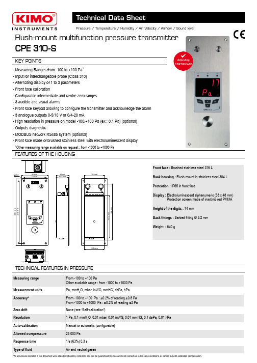
Flush-mount multifunction pressure transmitterCPE 310-SKEY POINTSFront face : Brushed stainless steel 316 LBack housing : Flush-mount in stainless steel 304 L Protection : IP65 in front faceDisplay : Electroluminescent alphanumeric (38 x 48 mm)Protection screen made of inactinic red PMMAHeight of the digits : 14 mm Back fittings : Barbed fitting Ø 5.2 mm Weight : 640 g- Measuring Ranges from -100 to +100 Pa 1- Input for interchangeable probe (Class 310)- Alternating display of 1 to 3 parameters - Front face calibration- Configurable intermediate and centre zero ranges - 3 audible and visual alarms- Front face keypad allowing to configure the transmitter and acknowledge the alarm - 3 analogue outputs 0-5/10 V or 0/4-20 mA- High resolution in pressure on model -100/+100 Pa (ex : 0.1 Pa) (optional)- Outputs diagnostic- MODBUS network RS485 system (optional)- Front face made of brushed stainless steel with electroluminescent displayFEA TURES OF THE HOUSINGTECHNICAL FEA TURES IN PRESSUREMeasuring range From -100 to +100 PaOther available range : from -1000 to +1000 Pa Measurement units Pa, mmH 2O, mbar, inWG, mmHG, daPa, hPa Accuracy*From -100 to +100 Pa : ±0.2% of reading ±0.8 Pa From -1000 to +1000 Pa : ±0.2% of reading ±2 Pa Zero drift None (see “Self-calibration”)Resolution 1 Pa, 0.1 mmH 2O, 0.01 mbar, 0.01 inWG, 0.01 mmHG, 0.1 daPa, 0.01 hPa Auto-calibration Manual or automatic (configurable)Allowed overpressure 25 000 Pa Response time 1/e (63%) 0.3 s Type of fluidAir and neutral gases234 m m92 mm44 mm 42.5 mm70 mm196 m m3.2218 m m76 mm69 mm147.3 m m *All accuracies indicated in this document were stated in laboratory conditions and can be guaranteed for measurements carried out in the same conditions, or carried out with calibration compensation.1Other measuring range available on request : from -1000 to +1000 PaPower supply 24 Vac / Vdc ±10 %Output3 x 0/4-20 mA or 3 x 0-5/10 V (4 wires)Maximum load : 500 Ohms (0/4-20 mA) / Minimum load : 1 K Ohms (0-5/10 V)Galvanic isolation On the output Consumption 5 WConformity CEM 2004/108/CE and NF EN 61010-1 directivesElectrical connection Screw terminal block for cables from 0.05 to 1.5 mm 2 or from 30 to 16 AWGRS485 communication Digital : Modbus RTU protocol, configurable communication speed from 2400 to 115200 Bauds (optional)Visual alarm Blinking of the value Audible alarmBuzzer (92 dB at 10 cm)Environment and type of fluid Air and neutral gasesOperating / storage temperaturesFrom -10 to +50 °C / From -10 to +70 °CTECHNICAL SPECIFICA TIONSSELF-CALIBRA TIONClass 300 transmitters have a temperature compensation system from 0 to 50°C and a self-calibration system to guarantee an excellent long-term stability, along with a great measurement accuracy.Self-calibration principle : the microprocessor of the transmitter drives a solenoid valve that compensates any long-term drifts of the sensitive element. The compensation is made by regular adjustment of the zero. The differential pressure measurement is then made regardless of the environmental conditions of the transmitter.INNOV A TIONSThe CPE310-S transmitter has a two adjustable pressure connections system in front face (A) coupled with two pressure connections at the back (B).When installing the transmitter, this system allows to configure the differential pressure connections with a set of plugs (supplied with the transmitter).➢Adjustable pressure connectionsThis system allows to isolate the back pressure connections and then to access the sensitive element (on the front face) of the pressure transmitter. Without dismantle the transmitter, this system allows to calibrate by connecting the transmitter to a pressure generator and acalibration bench. The calibration is easier and faster.➢Front face calibrationCONFIGURABLE ANALOGUE OUTPUTSConfigurable analogue outputs :Range with centre zero (-50/0/+50 Pa), with offset zero (-30/0/+70 Pa) or standard range (0/+100 Pa), it is possible to configure your own intermediate ranges. The minimum configurable range is 10% of the full scale.Configurable ranges according to your needs : outputs are automatically adjusted to the new measuring ranges+100-100+1000 V 4 mA 10 V 20 mA0050Newrange0 V 4 mA10 V 20 mA-100BSolenoid valve lifetime : 100 million cycles Advantage : no zero driftSelf-calibration frequency : can be disabled or set from 1 to 60 min➢Front face computer connectionMini-DIN connectionUSB connectionABlack-Red++-Red+Calibration bench24 Vac 12324 Vac ELECTRICAL CONNECTIONS – as per NFC15-100 standardThis connection must be made by a qualified technician. To make the connection, the transmitter must not be energized.24 Vdc power supply+➢For 24 Vdc power supply models :+Power supply terminal blockN ➢For 24 Vac power supply models :LPower supply terminal blockPe LN 230 Vac 24 Vac power supplyclass II~~or24 Vac power supplyN LPeL N230 VacN ➢Connection of the 0/4-20 mA current output :➢Connection of the 0-5/10 V voltage output :CONENCTIONSPressure connection +Pressure connection -A +B -Modbus :GND ALARMSThe CPE310-S pressure transmitter has 3 visual and audible alarms that are independent and configurable. Available settings are the followings : ●Time-delay duration : from 0 to 600 s ●Thresholds values ●Action of the alarm : rising edge, falling edge or monitoring ●Audible alarm activation (buzzer)INTEGRA TION OF PRESSURE MEASUREMENTThe pressure measurement element is very sensitive and reacts topressure changes. When making measurements in unstable air movement conditions, the pressure measurement may fluctuate. The integrationcoefficient (from 0 to 9) makes an average of the measurements ; this helps to avoid any excessive variations and guarantees a stable measurement.131415G N D – G r o u n d 0/4-20 m A –C u r r e n t 456OUT2G N D – G r o u n d 0/4-20 m A – C u r r e n t123OUT1NL ~~1230/4-20 m A – C u r r e n t G N D – G r o u n d 789OUT3-GND -mA +1 2 3+VRegulator display or PLC/BMS passive typeOUT1Regulator display or PLC/BMS passive type7 8 9OUT34 5 6Regulator display or PLC/BMS passive typeOUT27 8 9OUT34 5 61 2 3Regulator display or PLC/BMS passive typeOUT1Regulator display or PLC/BMS passive type+-+Regulator display or PLC/BMS passive type-For 24 Vdc powersupply models : -+orN e u t r a l (N )~P h a s e (L )~For 24 Vac power supply models :101112101112Power supply terminal block0-5/10 V – V o l t a g e0-5/10 V – V o l t a g e0-5/10 V – V o l t a g e101112--LGND mA VGND mA VGND mA VGND mA VGND mA VOUT2--++--+++-+-+-+-F T a n g _t r a n s m i t t e r _C P E 310-S – 20/12/13 – R C S (24) P ér i g u e u x 349 282 095 N o n -c o n t r a c t u a l d o c u m e n t – W e r e s e r v e t h e r i g h t t o m o d i f y t h e c h a r a c t e r i s t i c s o f o u r p r o d u c t s w i t h o u t p r i o r n o t i c e .MOUNTINGTo install a transmitter on a wall, make a cutting of 196 x 70 mm in the wall. Then drill 4 holes around the cutting as shown beside. Insert the transmitter into the wall and fix it with the 4 screws (supplied with the transmitter).MAINTENANCEAvoid aggressive solvents. When cleaning rooms or ducts with products containing formol, protect the the transmitter.OPTIONS●LCC-S : configuration software with USB cable ●RS5 : RS 485 Protocol Modbus digital output●HRP : high resolution (example in pressure : 0.1 Pa)●Calibration certificateCALIBRA TIONAdjusting and calibration on site : the professional configuration interface, with a dynamic pressure calibration bench, allows you to adjust and calibrate your transmitters directly on site or in laboratories.Outputs diagnostics : with this function, you can check with a multimeter (or on a regulator/display, or on a PLC/BMS) if the transmitter outputs work properly. The transmitter generates a voltage of 0 V, 5 V and 10 V or a current of 0 mA, 4 mA, 12 mA and 20 mACertificate : transmitters are supplied with an individual adjusting certificate and can be supplied with a calibration certificate as an option.RS 485 MODBUS PROTOCOLClass 310 transmitters can be linked in one network operating on a RS485 home bus.The RS 485 digital communication is a 2-wire network, on which the transmitters are connected in parallel. They are connected to a PLC/BMS via the RTU Modbus communication system. Since the CPE310-S can be configured with the keypad, the MODBUS enables remote configuration, to measure 1 or 2 parameters or to see the status of the alarms...CONFIGURA TIONClass 310 transmitters allows you to set all the parameters managed by the transmitter : units, measuring ranges, alarms, outputs, channels... via the different methods shown below : ➢Via keypad, only on models with display. A code-locking system for keypad guarantees the security of the installation. See configuration manual.➢Via software (optional) : simple and user-friendly. See LCC-S user manual.➢Via Modbus (optional) : configuration of all parameters from your PC, via the supervision or data acquisition software.INPUT FOR CLASS 310 INTERCHANGEABLE PROBESThe input for interchangeable probes allows to connect directly on CPE310-S transmitter, via the adaptor cable, an interchangeable probe of the class 310 range (see technical datasheet of probes for class310 transmitters).Advantage :the CPE310-S centralises, in addition of the pressure, temperature and humidity measurements of a SHDI150 probe for example.Adaptor connectionAdaptor for class 310 probes●Sliding fittings ●Connection fitting ●Clear tube●Pressure connections ●Trough-connectionsØ2.2mmCut-out depth =43mm70mm10m m196m m12m m3mm3mm。
高频压力传感器介绍
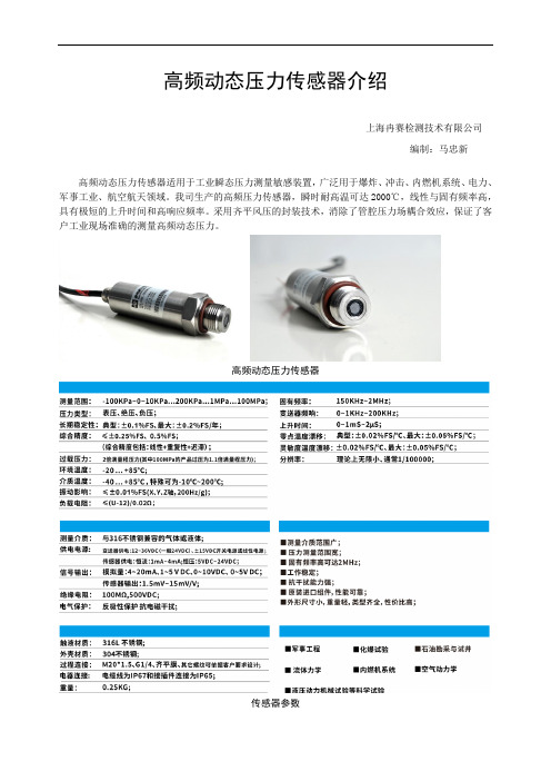
高频动态压力传感器介绍
上海冉赛检测技术有限公司
编制:马忠新
高频动态压力传感器适用于工业瞬态压力测量敏感装置,广泛用于爆炸、冲击、内燃机系统、电力、军事工业、航空航天领域。
我司生产的高频压力传感器,瞬时耐高温可达2000℃,线性与固有频率高,具有极短的上升时间和高响应频率。
采用齐平风压的封装技术,消除了管腔压力场耦合效应,保证了客户工业现场准确的测量高频动态压力。
高频动态压力传感器
传感器参数
接线定义
但在一些特殊测试工况下,为了不改变压力场或安装条件苛刻,需要更小的敏感传感器进行动态压力测量,我司结合客户需求,研发了微型动态压力传感器,解决了现场测试的难题。
微型动态压力传感器
微型压力传感器
微型压力传感器技术参数
微型压力传感器接线定义。
TESCOM中文样本

Cv = 1.3
• 可提供高精度的外部
PSIG
取压
• 平衡主阀设计增加了阀座寿命
26-1200 系列: 高流量
• 与上述 26-1100 类似
6,000 PSIG (414 Bar) 100-6,000 PSIG
更大的流量范围
Cv = 3.3 Cv =6.0 Cv = 12.0
0-1200, 0-1800
PSIG
铝 316 不锈钢
BB-5 系列: 袖珍型,两级减压
• 重量轻,设计紧凑
6,000 PSIG (414 Bar)
• 级间安全泄放接口
• 活塞感应,使用寿命长
• 无排放功能
0-80, 0-140,
Cv = 0.Байду номын сангаас6
0-220, 0-700,
0-1200 PSIG
• 设计紧凑
(414 Bar)
Cv = 0.24
• 挡块限制最大出口压力
• 入口及出口压力表接口为标配
• 标配无排放功能
黄铜 300 不锈钢 316 不锈钢
26-1000 多用途
26-1000 系列: 多用途
• 出口压力范围可
6,000 , 10,000 PSIG
现场调节
(414, 690 Bar)
• 多种接口选择
• 可选入口压力达
20,000 PSIG (1379 Bar)
• 大手柄设计,扭矩低
压力设定快速
• 标配带自排放功能
5-500, 5-800, 10-1500, 15-2500, 25-4000, 50-6000, 200-10,000 PSIG
Cv = 0.02 Cv = 0.06 Cv = 0.12 Cv = 0.3
- 1、下载文档前请自行甄别文档内容的完整性,平台不提供额外的编辑、内容补充、找答案等附加服务。
- 2、"仅部分预览"的文档,不可在线预览部分如存在完整性等问题,可反馈申请退款(可完整预览的文档不适用该条件!)。
- 3、如文档侵犯您的权益,请联系客服反馈,我们会尽快为您处理(人工客服工作时间:9:00-18:30)。
SCYG310高频动态压力变送器
一:产品概述
SCYG310系列高频压力传感器、变送器是为满足用户在响应频率、外形结构、工作温度等方面特殊要求而设计的产品。
产品利用微机械加工技术使得集成硅膜片有效尺寸小,固有频率高,有优良的弹性力学特性,采用感压膜片齐平封装设计,彻底消除管腔效应,传感器频响极高。
以响应频率特点将其定义为高频压力传感器。
综合性能优于压电式动态压力传感器,成为动态测试中压电压力传感器的换代产品
在军事工程、化爆实验、石油勘采与试井、材料、流体力学、土木工程学、岩土力学、创伤医学、液压动力机械实验、水工力学、燃弧实验等科学试验与现代化仪器仪表中,需要不失真的测量一些变化频率高、压力波形上升快陡的动态压力波形与幅值、有效值,这就要求所用压力传感器具有高的固有频率,极短的上升时间和宽广优良的响应频带,以保证足够的动态测压精度。
本产品防光抗干扰设计,可适用于近场爆轰动态试验测量,美国军标和我国军标爆轰动态测量标准中都推荐首选动态压阻式压力传感器。
本系列产品外形、技术参数多数需供需方沟通后设计生产,以臻最佳动静态性能效果。
二:产品特点
1.高频率响应
2.宽的通频带
3.宽工作温区
4.稳定性高,抗干扰能力强
5.量程范围广
6.产品性能长期稳定性好
7.尺寸可定制
三:典型应用
1.军事工程
2.化爆实验
3.石油勘采与试井
4.材料、流体力学
5.土木工程学
6.岩土力学
7.创伤医学
8.液压动力机械实验
9.水工力学
10.燃弧实验
四:性能指标
量程-100kpa……-1kpa~0kPa……10kPa……100Mpa
过压≤1.5倍满量程压力或110MPa(取最小值)
压力类型表压、绝压、负压
精度±0.1%FS ±0.25%FS ±0.5%FS
五:选型表
SCYG310-XXXX-X-X-X-X-X-X
请联系销售工程师协助您选型、确认具体技术参数。
综合精度(线性+重复+迟滞)
六:外形结构示意图
更多外形尺寸图,请联系销售工程师。
选型提醒:
1.选型时请注意被测介质与产品接触部分的兼容性。
2.若订货产品需要计量检定证书,或者其它特殊要求,敬请与本公司商洽,并在订单中注明。