ST500智能型电动机保护参数设置标准
ST500智能型电动机控制器简介

ST500智能型电动机控制器简介刘嘉祺秋风萧瑟,海波涌起。
不知不觉中,来到烟台分公司已经快半年了。
在这半年里,我们辛勤工作,为业主查实一个个问题;在这半年里,我们团结一致,给分公司打下坚实基础;在这半年里,我们充实自己,不断坚实自我的业务技能。
在烟台,我们奋勇前行,默默提高。
在万华,我们主要维保的石化区的两片装置是环氧丙烷和丙烷脱氢。
我所在的装置为环氧丙烷。
在我的工作范围,共计有366台低压电机,从电机的安装,电缆的敷设,控制回路的接线和最近的单试,我们都全程跟踪。
电机是电气施工的重点,也是我们以后保运的重点,所以了解电机控制就显得尤为重要。
下面为大家介绍烟台项目低压电机控制主要用到的ST500智能型电动机控制器(简称马保)。
本体单元互感器模块串口线操作显示模块上图为马保的组成模块。
利用马保能对所有低压电动机可能发生的各种情况进行保护并对各电气量、接触器的状态和开关位置进行监控,具有故障记录功能。
同时具备相应的遥控功能。
DI 功能整定表 序号 I DI 初始状态 功能整定 1 I.1 1DI 常开 本地正向起动 2 I.2 2DI 常闭 本地停车 3 I.3 3DI 常开 本地/远程 4 I.4 4DI 常开 远程起停A 5 I.5 5DI 常开 复位6 I.6 6DI 常闭 紧急停车(联锁)7 I.7 7DI 常开 通用DI 8I.8 8DI 常开 开关故障DO 功能整定表 注:OUT4设定成综合故障,是指装置故障和电动机故障。
DI 表示的是输入,OUT 表示输出。
马保有12个DI 点,一般的低压电机只用到1DI 到8DI ,每个DI 的含义如上表。
在马保中不同的DI 和OUT 所代表的含义不同的,这要明确的区分,并且最好要牢牢记住,这对以后的识图和故障处理都非常重要。
除了DI 、OUT 端子,在马保主体面板上还有AO-、AO+、DIC 、E1、E2、PE 、L 、N 端子,他们代表的意义不同,但也要熟记。
ST500II使用说明书-全套
ST500智能马达控制器的使用说明书(保护模式)(2003年)苏州智能配电自动化有限公司目录1、控制器的面板及端子功能说明 (1)2、控制器的功能配置一览表 (2)3、控制器应用接线图 (3)4、ST522显示模块 (3)5、控制器的使用说明 (4)5.1 控制器的主要功能 (5)5.2 控制器的参数测量功能 (5)5.3 控制器的报警查询功能 (5)5.4 控制器的故障查询功能 (6)5.5 控制器的维护管理功能 (6)5.6 控制器的输入输出状态查询功能 (7)5.7 控制器的各种保护定值设置功能 (7)5.8 控制器的系统参数设置功能 (16)1、控制器面板及端子标准配置复位”功能按钮或控制器断电一次则可清除热容量,允许立即起动电机。
注②:表中初始状态栏中的“常开”、“常闭”不是继电器的触点状态,而是指继电器线圈是否得电。
“常闭”指控制器上电后继电器线圈立即得电工作,“常开”指控制器上电后继电器线圈不得电。
保护模式下,A继电器的触点(14#/15#)为常闭接点,一般串联在电动机控制接触器线圈回路中,但当控制器上电正常工作时,A继电器立即得电吸合,仅在失电或发生故障保护后方再次断开。
漏电时,接地保护功能自动退出。
②控制器不带通讯功能时型号为ST501,增选通讯功能时型号为ST502(Profibus-DP),ST503(Modbus-RTU)3、控制器保护模式下的典型接线图器才自动闭合,允许电机再次起动运行。
保护模式下控制器提供装置失电/自诊断、故障跳闸等故障接点输出(图中19、20、21),其中自诊断接点为常闭,控制器得电正常工作时为常开,当控制器自检到装置故障或失电时变为常闭。
故障跳闸接点为常开,只有当控制器检测到故障并按规定特性保护动作时变为常闭。
分析排除故障后需按复位按钮方可清除故障指示和故障接点信号。
保护模式下控制器可据用户需要增选电压功能、电动机绕组热保护功能、漏电保护功能、4~20mA模拟量输出功能、通讯功能等。
ST500、YSK智能型电动机保护控制器技术介绍
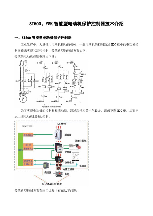
ST500、YSK智能型电动机保护控制器技术介绍一、ST500智能型电动机保护控制器工业生产中,大量使用电动机拖动的机械,一般电动机的控制通过MCC柜中的电动机控制回路来实现其运转控制,传统典型的控制方案如下:传统的电动机控制电路如下图:为了实现电动机的控制和相应功能,通过选择相关电气设备,组成下图MCC柜,从而完成上图电动机回路的控制。
传统典型控制方案在应用过程中存在以下问题:1.热继电器回路只能实现对电动机的过载保护,保护功能单一,要实现其它保护(如三相电流不平衡保护、缺相保护、接地/漏电保护、起动加速超时保护、欠载、欠压、过压保护、欠功率保护、抗晃电、欠压失压重起动保护),则必须靠在MCC柜增加其它电气设备来实现。
2.当电动机过载时,是靠热继电器本身的双金属片过流发热膨胀顶开触点来断开电气回路实施保护的,因此,热继电器无论是金属片还是输出的触点都无法做到与强电电气回路分开独立运行,其金属片和触点都要承受大电流的负载,特别是在过载情况下,金属片和触点会长期发热变形,从而使金属片产生机械疲劳失效现象和触点沾滞现象,导致保护拒动或误动3. 热继电器没有控制功能、没有测量且变送为4~20mA输出功能(三相电流、三相电压、功率、功率因素、频率、电能、热容量、电流不平衡率、漏电流值)、没有故障记录功能(当前运行时间、当前停车时间、累计运行时间、累计停车时间、起动电流、起动时间、操作次数、输入输出状态、故障记录、故障时标、运行状态指示)、没有控制回路电源检测、不带通讯功能,因此在DCS系统中要监视电动机的运行状态和参数,必须要在MCC柜附加相应设备和回路,并通过硬接线方式把信号反馈至DCS系统,既增加了设备又使回路构成变得复杂。
4.传统电动机控制回路由于采用热继电器构成回路,使MCC柜电气元器件多,回路构成复杂,无法实现设备的一体化,且故障点多。
采用我们的ST500系列电动机保护控制器,可以一站式解决上述问题和避免了故障点多的问题。
ST500智能型电机控制器技术说明书
自耦变压器起动(三继电器) 通讯功能 RS485 接口
通讯协议:Modbus-Rtu、Profibus-Dp
苏州智能配电自动化有限公司
功能配置
标配功能
增选功能
√
√
√
√
√
√
√
√ (温度保护)
√ (漏电保护)
√ (电压功能)
√
(选一种)
无
可选一种
4
ST500 智能型电动机控制器技术说明书
二. 技术参数……………………………………………………………………… 17
4.1 符号对照表………………………………………………………………… 17 4.2 测量显示误差……………………………………………………………… 17 4.3 保护设定参数……………………………………………………………… 18 4.4 各种保护特性说明………………………………………………………… 20
4.4.1 过负载保护 4.4.2 缺相不平衡保护 4.4.3 接地漏电保护 4.4.4 欠电流保护 4.4.5 堵转保护 4.4.6 过热保护 4.4.7 欠压保护 4.4.8 过压保护 4.4.9 欠功率保护 4.4.10 起动加速超时保护 4.4.11 外部故障保护 4.4.12 相序保护
五、特殊控制功能说明…………………………………………………… 25
苏州智能配电自动化有限公司
3
ST500 智能型电动机控制器技术说明书
息,报警信息,故障信息,可以进行参数设定(保护定值,系统参数等),可以输入操作控制 命令(如起动,停车等)。
ST500 手持编程器是一种手持设备,可用来对控制器进行参数整定和各种信息查询, 其功能类似于 ST522 显示模块,但不需和控制器一对一配套,仅是在现场调整参数或维护 查询时才用。
接触器配ST500智能型电动机控制器使用说明(直接启动模式)

ST500智能型电动机控制器(直接启动模式)使用说明1、ST500控制器端子功能说明2、控制器的应用电动机的综合保护、测量功能、各种控制功能由ST500完成;参数显示、参数设定、报警、故障、管理信息查询等功能由ST522完成。
当控制器上电时,首先通过控制器检测CJ接触器是否在释放状态,如果接线不正确控制器报“接线错误”;如果接线正确时控制器ST522显示“起动准备就序”缺省信息窗口。
当ST500接收到起动命令时,ST500内部A继电器吸合,则CJ接触器得电吸合,控制器检测到CJ吸合,起动过程中“起动”灯亮,ST522显示“正在起动”进程状况,表示电动机在起动过程中。
起动结束后“起动”灯熄灭,ST522显示“正在运行”的缺省窗口。
停车时,ST500内部A继电器分开,CJ接触器释放,主回路断开,电动机停车。
3、ST522显示模块在保护方式下,ST522操作显示模块和ST500控制器配合使用(通过T9**—02串口线连接),是ST500的可选部件之—,通过ST522可以实时显示电动机的各种测量参数;调整各种参数(保护定值、起动参数、系统参数);查询各种故障信息/报警信息/DI和D0状态;检测各种管理信息。
直接起动模式下ST522面板功能定义如下:3.1 指示灯“停车”指示当前电动机为停车状态。
“起动”指示电动机的停车和运行的中间状态,包括起动和转换过程。
“运行”指示当前电动机处于正常工作状态。
“报警”指示灯点亮时表示有非跳闸故障报警发生。
“故障”闪烁表示有跳闸故障,当前在处理过程中;恒亮表示当前处于故障跳闸状态。
3.2 功能键“起动A”在本地权限下,此按键可以控制电动机起动运行。
该控制按键据需要可锁定不用。
“停车”在本地权限下,此按键可以控制运行电动机停车。
该控制按键据需要可锁定不用。
“复位”清除故障显示,退出故障跳闸状态,但不能清除热容。
“返回”、“确认”“↑”、“↓”四个功能键用于参数设定和参数查询。
电机保护值的设定

要求不受电动机短时过载冲击电流或短路电流的影响而瞬时动作,通常采用热继电器作元件; 当 6 倍以上额定电流通过热继电器时,需经 5s 后才动作,可能在热继电器动作前,热继电器的加热元件已烧坏, 所以在使用热继电器作时, 必须同时装有熔断器或低压断路器等短路保护装置; 1失压保护电动机正常运转时如因为电源电压突然消失,电动机将停转;一旦电源电压恢复正常,有可能自行起动,从而造成机械设备损坏,甚至造成人身事故;失压保护是为防止电压恢复时电动机自行起动或电器元件自行投入工作而设置的保护环节; 采用接触器和按钮控制的起动、停止控制线路就具有失压保护作用; 因为当电源电压突然消失时,接触器线圈就会断电而自动释放,从而切断电动机电源;当电源电压恢复时,由于接触器自锁触头已断开,所以不会自行起动; 但在采用不能自动复位的手动开关、行程开关控制接触器的线路中, 就需采用专门的零电压继电器, 一旦断电, 零电压继电器释放, 其自锁电路断开,电源恢复时, 就不会自行起动; 2欠电压保护当电源电压降至60%~80%额定电压时,将电动机电源切断而停止工作的环节称为欠电压保护环节; 除了采用接触器有按钮控制方式本身的欠电压保护作用外, 还可采用欠电压继电器进行欠电压保护; 将欠电压继电器的吸合电压整定为 0.8~0.85UN、释放电压整定为 0.5~0.7 UN;欠电压继电器跨接在电源上,其常开触头串接在接触器线圈电路中,当电源电压低于释放值时,欠电压继电器动作使接触器释放,接触器主触头断开电动机电源实现欠电压保护;。
ST500EFMH智能型电动机控制器技术说明书(英文)
Directory1、overview………………………………………………………………………………………..2、Features…..……………………………………………………………………………………3、product model definition and function configuration table…………………………………3.1 model definition…………………………………………………………………………………3.3 ST500 serial products function table(function configuration of different model products see 3.4)…………………………………………………………………………………………………3.4 function configuration……………………………………………………………………………4、mount and chart………………………………………………………………………………...4.1 dimension chart of main body figure…………………………………………………………….4.2 figure dimension of CT………………………………………………………………………….4.3 figure dimension of display module……………………………………………………………..4.4 figure dimension of remained current CT………………………………………………………4.5 sketch map of main body faceboard…………………………………………………………….4.6 sketch map of display module faceboard……………………………………………………….5、typical application principle chart………………………………………………………………5.1 typical application of ST500F directly start……………………………………………………5.2 typical application of ST500F directly start……………………………………………………5.3 typical application of ST500M directly start……………………………………………………5.4 typical application of ST500H directly start……………………………………………………5.5 typical application of ST500E protection way………………………………………………….5.6 typical application of ST500E directly start…………………………………………………….5.7 typical application of ST500E double direction start……………………………………………6、main standard and technique data………………………………………………………6.1 product standard………………………………………………………………………………6.2 technique data…………………………………………………………………………………7、protection characteristic and working theory of controller…………………………7.1 atart overcurrent(blocked rotating)protection……………………………………………7.2start expedite OT protection…………………………………………………………………..7.3 overburden protection…………………………………………………………………………7.4 overcurrent(bloacked rotating)protection………………………………………………..7.5 tE time protection(applies to the incease-safety motor)……..…………………………7.6 underburden(undercurrent)protection…………………………………………………….7.7 current imbalance protection………………………………………………………………….7.8remained current(gounding)protection……………………………………………………7.9 remained current of high sensiivity(grounding)protection…………………………………7.10 overvoltage protection………………………………………………………………………..7.11 UVR protection………………………………………………………………………………..7.12underpower protection……………………………………………………………………….7.13phase sequence protection………………………………………………………………….8、control way…………………………………………………………………………………….8.1 restart function…………………………………………………………………………………8.2 automatically self start……………………………………………………………….............8.3 motor control right…………………………………………………………………………….1、OverviewThree phase AC asynchronous motor(shortened form motor below)is widely used in each field,it is especially important to ensure the safety control and economically run. Secondary control circuit of traditional motor is generally realized by the hard wiring, high cost,control principle and wiring is complex,workload of design、debug and maintenance is big, when problems appears, it is hard to investigate, protection of traditional motor mainly adopts thermal relay, protection range is narrow(cannot start motor when heavy load)、precision and reliability is low、power consume is big,caused many unnecessary economic loss, ST500 serial intelligent motor controller( shortened form motor below)integrates the technology of Computer、Control、Communication and CRT,also combines many kinds start scheme of motor,monitor the start of motor、run and the electric parameter when abnormal failure happens,utilize the fast disposal ability of microprocessor, according to rating parameter of motor, set time by user, limit value parameter whether normal to motor and failure sort, to correctly judge and distinguish to dispose,ensure the safety run of motor,and through the Chinese LED display、light to indicate、signal output、communication and many other form to inform users.Controller is applicable to the filed of rating frequency 50Hz、rating voltage to690VAC、rating current to 820A, in which motor is used, use of this product simplify the traditional secondary control protection circuit of the motor,provide the perfect motor control and protection method,as the intelligent terminal, it can also realizes the communication group net based on many kinds bus way,realizes the separated control protection and centralized management. The application of controller shorten the project circle, greatly improve the design and production efficiency,also reduces the amount of work that users debug and maintenance.This product adopts modular design,main body、special use current transformer and display module installed separately,volume of product is small, configuration compatible, mount conveniently,can be directly mounted and used in various drawer chest when at 1/4 modulus or above.2、Features●Assistant working power supply supports AC、DC(AC220V、DC220V/110V)●DI supports dry node(weak current DI)or wet node(weak current DI)input,wet node input can select AC or DC power supply.●Control DO supports AC load or DC load,meanwhile “start controlDO ”and“ protect/stop control DO” separate;signal DO is used in self detecting and failure alarm output, etc.●Measuring function is separated as basal measure(current parameter)andaccessorial measure(voltage parameter、remained current)●Supports various control logistic of motor(frequency conversion start、soft start、star-triangle start、two directions start、directly start, etc)●Protection function is separated as basal protection overload、block rotatingovercurrent, etc)and accessorial protection(tE time、remained current、overvoltage、under frequency, etc)●Parameters of protection function can be set at the scene by professional staffaccording to the actual parameters, will not lose when power off.●“tE time protection” meets the standard (GB3836.3-2000)●When extra big short current happens, can lock contactor,through control relay2DO to drive circuit breaker, reliably eliminate the failure.●“resist shaking current” function can ensure the motor continuous run,short timeUVR, lose voltage can realize the motor separate batch to restart(accessorial to select)●Controller can realized the motor start automatically function●4~20mAsimulated signal output can select the various run parameter of motor(accessorial)●Controller supports MODBUS-RTU、PROFIBUS-DP、DeviceNet doubleMODBUS-RTU and many other bus,realize data transmission function (accessorial)●Controller can record current run time、current stop time、accumulated run time、accumulated stop time、accumulated failure time、accumulated operating times,convenient for daily maintenance.●Controller can timely inquiry about I/O status of switching value、current motor runstatus●Controller can record motor eight times failure and failure time mark(standardmatched time clock),realize fast failure position fix.●Friendly human and machine interface:all Chinese LED display(accessorialattachment)3、product model definition and function configuration sheet3.1 model definitionST50 □□─□─□─□┼□┼□┼□┼□ST50 ST500 serial production model1 No communication function2 PROFIBUS-DP3 MODBUS-RTU4 DeviceNet5 Double MODBUS-RTU6 Double PROFIBUS-DPCommunicationF DI is dry node(internal installed DC24Vinput),control DO working powersource is AC220V/380VE DI is dry node(internal installed DC24Vinput),control working power sourceDo working power source is220V/380V,no control logicInput and output working power sourceM DI is wet node(AC220V input),control DOworking power source is AC220V/380VH DI is wet node(DC220V/110V input),control DOworking power source is DC220V/110VControl wayA Directly start controlB Double direction start controlC Frequency conversion start controlF star-triangle start control(two relays)G Resistance voltage reduced controlH Double speed start controlJ Protection wayM Autotransformer reduced voltage to control(two relays)S Soft controlRating current2A5A6.3A25A100A250A500A820ASelected functionV High voltage functionL (grounding) protection function for remained current of high sensitive(need to match special remained current transformer)M2 Analog signal output function(4~20mA)E tE time protection functionS “voltage+restart”function(resist shaking current、UVR、losing voltage restart)Omit will be no selected functionDisplay moduleST522ST522E( no control function)Serial port lineT910-02T915-02T920-02T930-02Remained current transformerZT30 500mA special using remained current transformer, range(50mA~500mA)ZT100 1000mA special using remained current transformer, range(100mA~1000mA)* when select L function, must choose one special using remained current transformerTM electronic arc-control device TMProtection parameter table:itemContentrangeRating power(Pn)250W ~100kW Rating voltage(Ue) 380V ~1200VmotorFull burden current(Ir1)2A(0.5~2A)、5A(1~5A)、6.3A(1.6~6.3A)、25A (6.3~25A )、100A(25~100A)、250A (63~250A )500A(250~500A)、820A (250~820A ) Acting wayalarm 、power offActuating value 20%Ir1~100%Ir1+OFF(close) Under burden protectionDelay time 0s ~50.00s Actuating wayalarm ,power offK coefficient10、16、24、40,60、80、100、130、180、280、400、600、800、1000、1100 1200、1400、1800 Cool time 0min ~1080minHot-cold curve ratio 20%~100% Start allowing heat capacity The 1st way ,the 2nd wayFailure reset way Manual 、automaticNot actuating trait 1.05Ir1OverburdenprotectionActuating trait 1.2Ir1 burden delay actuate in 2h Actuating way alarm 、power off Actuating value 5%~60%+OFF(close) ImbalanceprotectionDelay time 0.1s ~5.00s Actuating wayalarm 、power offMaximum breakingcurrent(Iic ) 200%Ir1~1000%Ir1+OFF(no limitActuating value 100%Ir1~Iic+OFF(close) Overcurrent protectionDelay time 0s ~50.00s Actuating way alarm 、power offActuating value20%Ir1~100%Ir1+OFF(close)Start delay time 0s ~60.00s Run delay time 0s ~60.00sRemainedcurrent (groundin g )protectionCutting coefficient 1.5~6.0+OFF (fixed time lag )Rating value of remained current transformer( I Δnm) 300~60000mA ,generally use 500mA 、1000mA Actuating way alarm 、switch offActuating value10%I Δnm ~100%I Δnm+OFF(close)Start delay time 0s ~60.00s Remainedcurrent of highsensitivity (grounding )protectionRun delay time 0s ~60.00s Actuating way alarm 、switch off Actuating value 75%~95%Ue+OFF(close) UVR protection Delay time0.1s ~50.00s Actuating way alarm 、switch off Actuating value 105%~150%Ue+OFF(close)Overvoltageprotection Delay time 0.1s ~50.00s Actuating way alarm 、switch off Actuating value 20%Pn ~95%Pn+OFF(close)Under power protection Delay time 1s ~60sStart expedite overtime Actuating way alarm 、switch off Actuating wayalarm 、switch offExternal failure Delay time 0.1s ~60.00s Phase sequence protection Phase sequence protection forbid 、enable Actuating way alarm 、switch offActuating value 100%Ir1~1000%Ir1+OFF(close) Startovercurrent protectionDelay time 0s ~50.00s Actuating wayAlarm 、switch off tE time 1.0~12.8+OFF(close) Not actuating trait1.05Ir1tE time protection Actuating trait1.2Ir1 burden delay actuate in 2h3.2 rating power、rating current reference sheet and selection function instruction ofelectromotor below:Rating power (kW)Ratingcurrent(A)SelectratingcurrentofcontrollerRatingpowerofmotor(kW)Ratingcurrentofmotor(A)SelectratingcurrentofcontrollerRatingpowerofmotor(kW)Ratingcurrentofmotor(A)Select ratingcurrent ofcontroller0.06 0.22 2A 7.5 14.8 25A 75 135 250A 0.12 0.42 2A 11 21 25A 90 165 250A 0.37 1 2A 15 28.5 100A 110 200 250A 0.55 1.5 2A 18.5 35 100A 132 240 250A 0.75 2 2A 22 42 100A 160 2851.12.5 6.3A 30 57 100A 200 3522.2 5 6.3A 37 69 100A 220 3883 6.5 25A 45 81 100A 250 437 5A+ZT40-500A CT5.5 11 25A 55 100 100A / / / note:date in the sheet applies to four polarity mouse case motor in AC400V、50Hz,1500 turn/min3.3 function sheet of ST500 serial products( function configuration of different model product see table 3.4)Measuring function Protection function Control way Maintenance andmanagement functionCommunicationfunctionI/O Other functionsThree phase current Start overcurrentprotectionDirectly start control Current run time MODBUS RTU 12 way switchingvalue(dry node orwet node)Simulating signaloutput(4-20mA)Three-phase voltage Start expediteovertime protectionDouble direction startcontrolCurrent stop time PROFIBUS DP-V0 3 way control D0,can select AC andDC“resist shakingcurrent”Effective power Overload reversedtime lag protection Double speed startcontrolAccumulated run time Double MODBUSRTU3 way signalalarmPower factor overcurrent(blockedrotating)protection Y-Δ start control(tworelay)Accumulated stop time DeviceNetfrequency tE timeprotection(applies toadd ampere motor) Resistance reducevoltage start controlStart timeEffective power energy underburden/undercurrentprotectionAutomatic reducedvoltage startcontrol(two relays)Start timeThermal capacity Currentimbalance/phasebreakSoft starter control Operating timesCurrent imbalance ratio Remainedcurrent(grounding)protectionFrequency conversionstart controlI/O statusRemained current(groundin g) Overvoltage protection UVR and loosingvoltage restart control8 times failure recordUVR protection Self start control whencurrent onFailure time remarkUnder powerprotectionNo control(protectionway)Run status indicationPhase sequenceprotectionPT breaking line lockclosedExternal failureOverflowfailure(directly startcontrol or protectionway)3.4 function configurationST500F series function configurationST500M series function configurationST500H series function configurationST500E series function configurationfunction contentStandard matchedaccessorialStandard matchedaccessoriaStandard matchedaccessorialStandard matchedaccessorialThree phase current √ √ √ √ Three phase voltage √ √ √ √ Effective power √ √ √ √ Power factor √ √ √ √ Frequency√ √ √ √ Effective power energy √ √ √ √ Thermal capacity√ √ √ √ Current imbalance ratio√ √ √ √ Remained current(grounding )(0.3-1.0)Ir1√ √ √ √ measureRemained current (grounding )50-1000mASelect one √ √ √ √ Start overcurrent protection √ √ √ √ Start expedite OT protection√ √ √ √ Overburden reversed time lag protection √ √ √ √ Overcurrent (blocked rotating)protection √ √ √ √ tE time protection(applies to ampere adding motor)√ √ √ √ under burden/undercurrent protection √ √ √ √ Current imbalance /phase breaking√ √ √ √ Remained current(grounding)protection :(0.3-1.0)Ir1√ √ √ √ Range of remainedcurrent(grounding)protection :50-1000mA √ √ √ √ Overvoltage protection √ √ √ √ Under voltage protection √ √ √ √ Under power protection √ √ √ √ Phase sequence protection √ √ √ √ PT line breaking lock closed √ √ √ √ External failure√ √ √ √ protectionOverflow failure(directly start control or protection way) √ √ √ √ Directly startTwo directions startFrequency conversion start star-triangle start( two relays ) Resistance reduced voltage to startDouble speed start Control modeProtection waySelect one√√√Autotransformer reduced voltage to star( two relays) Soft starterVoltage +restar“resist shaking current ”、UVR )restart√ √ √ √Attached table :ST500F series function configurationST500M series function configurationST500H series function configurationST500E seriesfunction configurationfunction contentStandard matchedaccessorialStandard matchedaccessorialStandard matchedaccessorialStandardmatchedaccessorialMODBUS-RTU PROFIBUS-DPDouble MODBUS-RTU Communic ation functionDeviceNetSelect one √ √ √ √Simulating signal function One way 4~20mA output ,transmit variation and can be programmable √ √ √ √ Timely clockyear 、month 、date 、hour 、min 、sec √√√√Protection parameter System parameter I/OStart parameterParameter setAlarm informationFailure information I/O state informationOperating times Failure times Stop timeParameter setinformation inquiry Run timeInformation inquiryNeed to match display moduleNeed to match display moduleNeed to match display moduleNeed to match display module12 way switching value dry node( internal installed DC24V )√√12 way switching valuewet node (AC220V ) √ 12 way switching value wet node (DC220V ) √ Switching value input12ay switching value wet node (DC110V )Select one √ 3 control DO (AC burden ) √ √ √ Switching value output 3 control DO (DC burden ) Selectone√ LEDindicationstop/run 、bus 、failure/alarm√√√√note:4-20mA transmitting variation program range:Ia、Ib、Ic、Iav、Ua、Ub、Uc、Uav、Δa、Δb、Δc、Δav、F、P4、mount and chart4.1 shape of main body dimension chart4.2 figure dimension of CTUsers can select fixed mounted or standard rail mounted wayØFigure and mounting dimension chart of100A house CT6、main standard and technique data6.1 product standardGB 14048.1 low voltage switchgear and control device general principlesGB 14048.4 low voltage switchgear and control device low voltage mechnical and electrical form contactor and motor starterGB 14048.5 control circuit electrical components and switch component mechanical and electrical form control circuit electrical components GB 3836.3-2000 exploding condition use electrical deviceThe third section:ampere adding“e”JB/T10613-2006 digital motor compositive protection device common use technicalconditionJB/T10736-2007 AC motor protectorGB/T 18858.3-2002 low voltage switchgear and control device controller-device interface(CDI)the third section:DeviceNetGB/T 20540.1-6-2006 measure and control digital communication industry control systemuse scene bus type 3: PROFIBUS criterion6.2 Technique dataMain circuitRating working voltage(Ue)400V/690VRating insulating voltage(Ui)690VController rating current (Ir1)2A、5A、6.3A、25A、100A、250A、500A、820ARating working frequency 50Hz Insulating resistance 100MΩ/500VMedium intension test 2kV(r.m.s),50Hz,1minInsulatingtest Rush voltagetest 5kV(peak),1.2/50us,0.5J 3 plus,3minus,interval 5sAuxiliary working power supplyRating working voltage(US)AC85~264V,DC100~300VPower consume 8W /8VAWorking conditionWorking allowingtemperature-20℃,70℃Storing temperature -25℃,85℃Mounting altitude 2000mMounting type IIIProtection grade Main body:IP20;display module:IP45 Control relay outputControl relay output capacity E/F/MResistance trait:AC240V 8AAC-15:AC240V 3AAC380V 1.9Aresistance trait type product resistance trait type productHResistance trait:DC125V 10ADC250V 1.5ADC-13:DC125V 2.2ADC250V 0.2A type product type productmaximum breaking voltage E/F/M: 400VAC H:300VDCMaximum breaking ability AC E/F/M: 2000VA H:4000VASignal relay outputAC250V 5A(resistance trait)Output capacityDC30V 3A(resistance trait)maximum breaking voltage 300VACMaximum breaking abilityAC1500VAEMC electric magnetic compatibleElectrical fast conversionimpulse group anti-disturbdegree testRigor grade is IV gradeRadiofrequency electromagnetic radiation anti-disturb test Field force 10V/m,scan speed 1.5*10-3ten multiples/SStatic discharge anti-disturb test Grade is gradeⅢsurge(rush)anti-disturb test Power supply and I/O 4 kv,communication 2kvIndustry frequencymagnetic field anti-disturbtestRigous grade is IV gradeElectromagnetic shoot test In ten meters measuring distance, radiation shoot limited value:40dB(µV/m)Voltage temporary reduced、short time cut and voltagechanging anti-disturb test50 ms7 、protected characteristic and working theory of controller7.1 start over current(blocked rotating)protectionDuring start, according to the ratio of the maximum current measuring value and motor rating current to decide whether start this protection. This function is put into use in the process of start, automatically close lock after starting then change to run status .Set randgeOvercurrent range 100%Ir1~1000%Ir1,OFF(close)Actuating way alarm/alarmActuating time 0 ~50.00s7.2 start expedite OT protectionafter reaching start time,through testingthe motor loop current whether reduces tobelow 110% of motor rating current, to decidewhether to start this protection. Forincrease-safety motor , start time cannot beset 1.7 multiples tE time. In the chart, whenthe set time is T1, because current isn ’t reduced below 110%Ir1,so is judged as start expedite OT, controller send the protection action signal ,if set time is T2, can enter run status. In the set start time ,motor hasn ’t finished starting ,protection action to 5DO relay.Set rangeStart time range 1.00s ~60.00s Actuating way switch off/alarm Actuating time instant actuate7.3 overburden protectionmotor frequently start management, thermal memory function have significant mean to the frequently start motor field. Controller simulates heat capacity under various run status, timely monitor the heat condition of motor, effectively protect restart under overheatcondition ,can make use of the motor atmaximum degree ,also can ensure the motor ’s safety ,ensure the continuous run of motor. Below chart is the heat capacity when frequently start ,only when the heat capacity cool to the “ forbid ” line, can send the wellprepared signal , allow to start the motor again. start allowing heat capacity (heat capacity on “forbid ” line ) is divided two kinds ,one is the fixed heat capacity is15%(the 1st way );the other heatcapacity only needs to satisfy(100%-heat capacity produced by last time start-2%) or 15% ( the 2nd way ).Note :in special condition, to make the motor continues run ,can forcedly clear the heat capacity in memory, immediately start the motor, this function need ST500 series controller support.Overburden failure resetAfter overburden failure switch off, provides automatic and manual two kinds reset ways for users to choose.“ automatic reset ”way is failure reset automatically after motor overburden failure switches off ,heat capacity reduces to below allowing start heat capacity ,not need to through reset operation can start again ;“ manual reset ”way is failure cannot be cleared automatically, need to manual reset, otherwise not allow to start motor.Set rangeProtection actuating way switch /alarmCurve speed K 18 kind for choose Cool time 0min ~1080min Failure reset way manual/automaticStart allowing heat capacity the 1st way 、the 2nd way Cool-heat curve ratio 20%~100%characteristicwhen motor runs under the overburden failure, controller computes the heat capacity I 2t according to the heat characteristic of motor, simulate motor heat characteristic to protect the motor. Overburden protection has 18 characteristic curves for choose, see time table 、overburden characteristic curve chart 、curve speed table.100%0禁止作热容量Trip time under the appointed conditionCurve speed KSatisfyprotectiongradeCommutemultiples1.05 1.2 1.5 7.210-80 2 ≤2min Tp≤2s 24 3 ≤2min 2s<Tp≤3s 40 5 ≤2min 3s<Tp≤5s130、180 10A ≤2min 2s<Tp≤10s280 10 ≤4min 5s<Tp≤10s 600 20 ≤8min 10s<Tp≤20s1100 30 ≤12min 20s<Tp≤30s1800 40 Trip timeNotactuate in2 hActuatein 1h- 30s<Tp≤40sOverburden protection characteristic curve, see chart below, time table of overburden actuating characteristic, see attached table one .X Ir1Curve speed comparable tableCurve speed 1 2 3 4 5 6 7 8 9 10 11 12 13 14 15 16 17 18 correspondingK -value 10 16 24 40 60 80 100 130 180 280 400 600 800 1000 1100 1200 1400 18007.4 overcurrent(blocked rotating)protectionAccording to the ratio of maximum line current measuring value and rating current of motor, todecide the motor whether in overcurrent status, when current is higher than fixed value, it willstart the overcurrent protection.Set rangeActuating value 100%Ir1~Icu actuating time 0 s ~50.00sactuating way switch off/alarm contactor allows breaking current Icu Icu set range 200%Ir1~1000%Ir17.5 tE time protection( applys to the safety-increased motor)Provide heat overburden protection when in tE time to break the motor power supply when blocked rotating ,only after the motor finished starting then put into use. Protection actuation to 5DO relay.Characteristic curve :I A /I E22107892345643551210810152050t E p (S )10Set rangetE time set tEp 1.0s ~12.8s,OFFin : tEp: allow blockced rotaing time when 7 multiples rating current IA: blocked rotating current(that is I) IE: rating current of motor ( that is Ir1) Actuating conditionProtection devotion openMotor finishes start, then enter run status, protection actuates.Start when current is equals or higher than two multiples rating current,actuate following below curve.tE time protection characteristic table see the 2nd attached table. 7.6 under burden (undercurrent )protectionWhen burden with motor appears broken or pump empty rotates, then it will appear under burden, the latter will cause the damage of facility.Under burden protection decides whether to start according to the three phase average value of motor loop. Set rangeActuating value 20%Ir1~100%Ir1Actuating time 0 s ~50.00s Actuating way power off/alarm Actuating conditionIn the actuating time,the current is below the set value all the time.7.7 current imbalance protectionSeparately compute three phase imbalance rate,through compare the max imbalance rate and set imbalance protection actuating value of three phase, to determine whether to start the imbalance protection. Phase breaking is the limited status of imbalance, imbalance rate when phase break is1 100%,production immediately actuate the protection. The computing formula of imbalance rate: |I-Iav|/Iav,Iav is the average value of three phase,when Iav is below to Ir1,the denominator use Ir1.When the motor happens phase lacking or three phase imbalance, protection to 5DO relay. Set rangeCurrent imbalance rate 5%~60%,OFFActuating time 0.1s~5.00sActuating way switch off/alarm7.8 remained current(grounding)protectionAutomatically computes remained current,not need to external connect CT,afterprotection actuates,aHas fixed time lag and reversed time lag characteristic, its current signal is got from theinternal CT current vector sum, is used to protect the phase line short circuit protection to metal house of motor. Actuating current characteristic :when≤ 0.9Iq, not actuate,when ≥1.1Iq delay actuate. Grounding delay time characteristic: t = Ir1 / I * C * Tqthereinto:t----failure delay time;Ir1 ---motor rating current;I---grounding failure current;C----cut coefficient;Tq-----grounding set delay time;Iq-----grounding set value.When C is set as OFF, actuating characteristic is the fixed time lag.Set rangeActuating value 20%Ir1~100% Ir1,OFF(Ir1 motor rating current)S t art delay time 0s~60.00sRund elay time 0s~60.00sCut coefficient C 1.5~6.0,OFF(when C is set as OFF, actuating characteristic is fixed time lag,whereas is the reversed time lag.)Actuating way switch off/alarm。
ST500马达智能控制器在工业生产过程控制中的应用[1]
操作功能具有:直接启动,可逆启动,V△启动,停车等控制功能外,可以编程就地操作
或者设成远端控制,另外还通过编程器实现断路器的“三遥”测控单元.
保护功能具有:过载反时限(多种曲线可选),过流,漏电接地,欠流,相不平衡,热保 护,接触器吸合状态检测,起动超时,欠压等保护功能. 监视功能:三相运行电流显示,电机启动电流显示。 维护功能:启动次数,运行时间,接触器故障,历史故障信息查看,报警信息显示等功能。 通讯功能:具有RS485接口,可挂接PROFIBUS现场总线,MODBUS现场总线。可实现
量简单。ST500正是围着这一点设计的。 1.IST500本身除具备正常的直接启动、可逆启动、Y-△启动、停车等控制功能外,还能通过编 程器,可以编程为就地操作或者设成远端控制.使得传统方案中复杂的二次接线,如:起停逻
辑电路,电气互锁逻辑电路,都被取消掉,ST500的一切逻辑都由芯片完成,大大地降低了接
展的方向。 微机式智能保护设各可靠性,安全性在不断提高,其功能也更加完善,应用更加广泛。以
国外著名的电气公司相继推出低压电动机综合保护和控制设备为标志,一种全新的低压马达控
制保护解决方案诞生,比较有代表性的有:阿尔斯通公司,罗克韦尔公司,东芝公司,西门子
公司。ST500是目前国内具有国际水平的马达智能保护控制单元。在国内具有一定代表性。 S”00在电动机控制中,取代了传统方案中许多繁杂的二次接线,仅需接触器配合就可完
4.2总线组网 ST500可通过串行接口.实现与现场总线系统的连接,通过通讯组网,可实现“四遥”监
控管理。
总线系统结构分两种分别如下图:
(1)系统结构图
132
图n
图12 图11结构可选MODBUS或PROFIBUS两种协议进行数据传输,ST500选用PROFIBUS时,N最多可选127个站,但每31个从站之间
ST500系列产品使用手册
侧视图
安 装 方 式 : 1、 安 装 于 35mm标 准 导 轨 2、 定 位 孔 处 镙 孔 安 装
19
15
102
4
顶视图
3 16
定位孔 *4
16 10
66
侧视图
顶视图
安 装 方 式 : 1、 定 位 孔 处 镙 孔 安 装 2、 与 本 体 装 置 组 合 安 装
SCT安装尺寸 SCT5,SCT10
概述
ST500系列产品型号及应用范围
产品型号 ST500M:经济型电动机保护测控装置 ST500H:综合型电动机保护测控装置 ST500F:增强型电动机保护测控装置 ST500:高端型电动机保护测控装置
SCT选型
SCT型号 SCT5 SCT10 SCT30 SCT100
电动机额定电流 5A及以下 10A及以下 30A及以下 100A及以下
西安龙云电力科技有限公司
ST500系列产品功能配置表
型号 功能
短路保护
堵转保护
定时限过流保护
反时限过流保护
保 欠载保护 护 缺相/不平衡保护
零序过流保护 功
TE时间保护 能 欠压保护
过压保护
工艺连联锁
晃电再启动
溢出故障
电压测量
电流测量 测
功率测量 量
功率因素 功
频率测量 能
电能测量
漏电电流测量
开关遥控 控
目录
1、概述 ------------------------------------------------------------------------------------------1 2、ST500系列产品型号及应用范围 -----------------------------------------------------------------1 3、SCT选型 ---------------------------------------------------------------------------------------1 4、ST500系列 产品 主要 特点 ------------------------------------------------------------------------1 5、ST500系列产品功能配置表----------------------------------------------------------------------2 6、ST500系列 产品技 术参 数表 ----------------------------------------------------------------------3 7、ST500系列产品安装----------------------------------------------------------------------------4 8、ST500产 品端 子介绍 -------------------------------------------------------------------7 9、ST500系列产品接线原理图---------------------------------------------------------------------7 10、ST500系列产品 施工注意事项 -------------------------------------------------------------------10 11、ST500系列产品操作---------------------------------------------------------------------------10 12、ST500系列产品保护功能-----------------------------------------------------------------------15 13、ST500系列产品参数设置-----------------------------------------------------------------------20 14、电动机控制功能--------------------------------------------------------------------------------21 15、电动机操作原理--------------------------------------------------------------------------------21
500KW高压电机保护数字设置
制二 V X X V V X V X X V X X V V X
500kw高压电机数字保护设置 控制一 运行堵转T 启动堵转T 电流速断T 过电流T 负序速断T 零序延时T 低压延时T 过压延时T 过负荷延时T 过负荷定值T 运行堵转T 启动堵转T 运行速断T 启动速断T 运行过流T 启动过渡T 运行反时限T 启动反时限T 负序速断T 负序过流T 20 4 0 10 0.1 0.3 20 20 30 6 10 15 40 30 8 12 15 20 1 2 启动定值I 零序定值I 有流定值I 额定电流I T1 T2 热保护T 热告警系数 低压定值 过压定值 4 0.5 0.1 3.95 5 0 0.1 0.5 88 110 控制二 本体保护1跳闸投入 本体保护1跳闸退出 本体保护跳闸投入 本体保护跳闸退出 CT断线投入 CT断线退出 电流标准反时限投入 电流标准反时限退出 电流非常反时限投入 电流非常反时限退出 电流极端反时限投入 电流极端反时限退出 负序标准反时限投入 负序标准反时限退出 负序非常反时限投入 负序非常反时限退出 负序极端反时限投入 负序极端反时限退出 CT断线闭锁负序保护 CT断线不闭锁负序保护 PT断线监视投入 PT断线监视退出 零序电流投入 零序电流退出 零序过流跳闸 零序过流告警 负荷投入 负荷退出 过负荷跳闸 过负荷告警 控制回路断线投入 控制回路断线退出
- 1、下载文档前请自行甄别文档内容的完整性,平台不提供额外的编辑、内容补充、找答案等附加服务。
- 2、"仅部分预览"的文档,不可在线预览部分如存在完整性等问题,可反馈申请退款(可完整预览的文档不适用该条件!)。
- 3、如文档侵犯您的权益,请联系客服反馈,我们会尽快为您处理(人工客服工作时间:9:00-18:30)。
ST500参数设置
1.保护参数设置
1. 过载保护
1) K系数
K系数的设置一般和电动机的过载能力曲线有关,或者可以根据电动机的过载保护级别来设定,但国内很多电动机没有以上两项数据,可以参考下面的设置标准进行设置。
该参数主要反映的是电动机过载动作的速度。
标准型(10级):7.2In(In为电动机额定电流),4—10s动作,用于标准电动机过载保护,速动型(10A级):7.2In时,2—10s动作,用于潜水电动机或压缩电动机过载保护。
慢动型(30级):7.2In时,9—30s动作,用于如鼓风机电机等起动时间长的电动机过载保护。
根据以上参数,对照说明书中电流-时间特性表设置K。
2) 冷热曲线比
该参数设置主要影响电动机在没有过载情况下热容量的计算。
热容量计算主要分为两个部分,没有过载情况下的热容量(稳态热容量)和过载情况下的热容量(过载热容量)。
过载后热容量的计算是以稳态热容量为基础开始叠加。
也就是说冷热曲线比主要影响过载热容量的起点。
若不需要考虑电动机在没有过载情况下的发热,该参数可以设置为100%,若考虑电动机在没有过载情况下的发热,可以根据电动机在没有过载情况下的发热程度设置该参数,该参数设置越小,稳态热容量的值越大,电动机在没有过载情况下的发热越厉害。
电动机没有过载情况下的回路电流
稳态热容量= ×(100%-冷热曲线比)
电动机额定电流
3) 冷却时间
该参数主要影响电动机过载动作后复位时间。
对该参数影响较大的是电动机的散热条件。
若散热条件比较好的该参数可以设置小一些,若散热条件差的该参数可以设置大一些。
实际上该参数类式热继电器的双金属片动作后恢复到初始位置的时间。
若没有达到冷却时间电动机不允许再次起动,但可以通过清除热容量的方式来再次起动电动机。
4) 允许起动热容
该参数主要决定电动机过载动作热容量降低到什么程度后可以重新起动电动机。
方式一:降低到15%以下可以再次起动电动
机;方式二:降低到(100%-上次起动所有热容量-2%)或者降低到15%以下可以再次起动电动机,一般设置为方式一较为合理一些。
5) 故障复位方式
过载故障动作后要求再次起动的情况下,若热容量已经下降到允许起动热容量以下,故障复位方式为自动时可以直接起动电动机;若热容量已经下降到允许起动热容量以下,故障复位方式为手动时需执行一次复位操作才允许起动电动机。
一般该参数可以设置为自动。
6) 保护动作方式
保护的动作执行方式为报警,当回路出现过载故障时,控制器发出报警,但不会断开主回路,电动机会一直运行;保护的动作执行方式为跳闸,当回路出现过载故障时,控制器发出报警,延时时间到后断开主回路,电动机停车。
2. 堵转保护
1) 动作值
2) 允许分断电流
接触器一般的分断电流在6~8倍额定电流左右,若回路中的故障电流大于该数值时,强行去分断接触器可能会造成接触器烧毁,同时电动机也不能正常停下来,可能还会导致事故的进一步扩大,该参数的设置主要是针对电动机回路中故障电流大于接触器正常分断能力的情况下不去分断接触器,而是通过和上面的SCPD配合动作。
3) 延时时间定时限保护
4) 保护动作方式同1
3. 缺相不平横保护
1) 动作值
不平衡值的计算:
当回路电流<电动机额定电流时:
| 回路中某项电流-平均电流 |
不平衡率= ×100%
电动机额定电流
当回路电流>电动机额定电流时:
| 回路中某项电流-平均电流 |
不平衡率= ×100%
平均电流
2) 动作时间定时限保护
保护动作方式同1 4. 起动加速超时保护
1) 起动时间
2) 保护动作方式同1。