卷积编码和Viterbi译码
卷积码的编码及解码Viterbi解码Word版
卷积码的编码及解码(Viterbi 解码)一、实验目的1、了解卷积码的基本原理;2、掌握卷积码编码的电路设计方法;2、掌握卷积码 Viterbi 译码的基本方法和电路设计方法。
二、实验仪器1、移动通信实验箱一台;2、台式计算机一台;三、实验原理1.卷积码编码原理卷积码是一个有限记忆系统,它也将信息序列切割成长度 k的一个个分组,与分组码不同的是在某一分组编码时,不仅参看本时刻的分组而且参看本时刻以前的 L 个分组。
我们把 L+1 称为约束长度。
2.卷积码的译码算法(硬判决 Viterbi 译码)Viterbi译码算法是一种最大似然算法,它不是在网络图上依次比较所有可能的路径,而是接收一段,计算,比较一段,保留最有可能的路径,从而达到整个码序列是一个最大似然序列。
Viterbi解码算法的基本步骤如下:1、从某一时间单位j=m开始,对进入每一状态的所有长为j段分支的部分路径,计算部分路径度量。
对每一状态,挑选并存储一条有最大度量的部分路径及其部分度量,称此部分路径为留选(幸存)路径。
2、j增加1,把此时刻进入每一状态的所有分支度量,和同这些分支相连的前一时刻的留选路径的度量相加,得到了此时刻进入每一状态的留选路径,加以存储并删去其他所有的路径。
因此留选路径延长了一个分支。
3、若j<L+m,则重复以上步骤,否则停止,译码器得到了有最大路径度量的路径。
上面的过程可以简单的总结为“加、比、选”(也称ACS)。
四、实验步骤1、将实验箱和计算机通过串行口连接好,为实验箱上电。
2、将与实验箱相连的电脑上的学生平台程序打开。
在“实验选择”栏中选择“卷积码”实验,点击确认键。
从而进入此实验界面。
3、在实验界面上点“生成数据”,让系统生成待编码的随机比特。
也可在界面上直接双击所显示的 bit,修改其值。
4、在界面上点击下发“原始数据”,该数据将被送入单片机(或 CPLD)进行卷积编码然后经过编码的数据被送回学生平台并显示在“编码数据”栏。
DRM系统中卷积编码及Viterbi译码的实现

( . k 1z
U i r , a gh uz u e H n zo k vs
300 , h 0 C i a
2 u t cm Tl o o L . H nzo k . T S r e c C . t , ag huz ao em d
维普资讯
信 号 与 信 息 处 理
D M 系统 中卷 积 编 码 及 V tr i 码 的 实现 R i b译 e
章 宇 , 马 彬
(. 1 浙江大 学 计 算机 学 院, 江 杭 州 30 0 ; 浙 10 0
2U . T斯达康 通讯 有 限公 司 , 浙江 杭 州 3 00 ) 10 0
Absr c T e c n ou in lc dn n i r id c dn s a fe t e fr o d er rc re t n meh d, n ti d l s d n mo ie ta t h o v lto a o ig a d vt b e o ig i n e ci o w r ro o rci to a d i swiey u e i b l e v o c mmu iain d s tli o o nc to sa aelt c mmu iain I i a e , rs n t a piain i n e n c to s.n t s p p r we pe e ti h s p lc t n DRM y tm . e s f r to s gv n a o s se Th ot e me d wa ie s a wa h
p vd sa g o to o d a t o e n DRM ytm . o r ie o d me d t e lwi c d si h h s se Ke r s DRM ; u cu e o v lt n lc d s; i r e o ig y wo d p n tr d c n oui a o e vt bid c dn o e
Viterbi译码的MATLAB仿真研究

BUPT卷积码编码及Viterbi译码班级:07114学号:070422姓名:吴希龙指导老师:彭岳星邮箱:FusionBupt@1. 序言卷积码最早于1955年由Elias 提出,稍后,1957年Wozencraft 提出了一种有效地译码方法即序列译码。
1963年Massey 提出了一种性能稍差但是比较实用的门限译码方法,使得卷积码开始走向实用化。
而后1967年Viterbi 提出了最大似然译码算法,它对存储级数较小的卷积码很容易实现,被称作Viterbi 译码算法,广泛的应用于现代通信中。
2. 卷积码编码及译码原理2.1 卷积码编码原理卷积码是一种性能优越的信道编码,它的编码器和解码器都比较易于实现,同时还具有较强的纠错能力,这使得它的使用越来越广泛。
卷积码一般表示为(n,k,K)的形式,即将k 各信息比特编码为n 个比特的码组,K 为编码约束长度,说明编码过程中相互约束的码段个数。
卷积码编码后的n 各码元不经与当前组的k 个信息比特有关,还与前K-1个输入组的信息比特有关。
编码过程中相互关联的码元有K*n 个。
R=k/n 是编码效率。
编码效率和约束长度是衡量卷积码的两个重要参数。
典型的卷积码一般选n,k 较小,但K 值可取较大(>10),以获得简单而高性能的卷积码。
卷积码的编码描述方式有很多种:冲激响应描述法、生成矩阵描述法、多项式乘积描述法、状态图描述,树图描述,网格图描述等。
2.1.1 卷积码解析表示法卷积码的解析表示发大致可以分为离散卷积法,生成矩阵法,码多项式法。
下面以离散卷积为例进行说明。
卷积码的编码器一般比较简单,为一个具有k 个输入端,n 个输出端,m 级移位寄存器的有限状态有记忆系统。
下图所示为(2,1,7)卷积码的编码器。
若输入序列为u =(u 0u 1u 2u 3……),则对应两个码字序列c ①=(c 0①c 1①c 2①c 3①……)和c ②=(c 0②c 1②c 2②c 3②……)相应的编码方程可写为c ①=u ∗g ①,c ②=u ∗g ②,c=(c ①,c ②)。
FEC前向纠错,卷积编码之维特比译码
FEC前向纠错,卷积编码之维特⽐译码因为要学习做WCDMA的流程解析,需要先提取卷积数据,⾸先就要做FEC卷积译码。
于是⽹上翻了好⼤⼀圈,特地学习了下viterbi译码算法,费很⼤⼒⽓才凑齐能够正确跑起来的代码,特记录⼀下。
说点题外话:viterbi是个⼈,全名Andrew J. Viterbi,⼀枚数学家,美国⾼通公司的创始⼈之⼀(没错,就是现在⼿机上那个⾼通芯⽚的⾼通),现代⽆线数字通讯⼯程的奠基⼈。
此外,viterbi算法不但可⽤来做卷积译码,另外⼀个⼴泛的应⽤是做股票证券量化预测计算(隐马模型预测)。
没错,就是⾼频量化交易炒股的算法基础。
美国量化对冲基⾦的传奇,⼤奖章基⾦背后的⽼板James Simons,⾸创将隐马模型预测⽤于炒股,也是⼀枚数学家。
两枚玩数学算法的巨富,谁说学数学算法没⽤的?FEC前向纠错译码⽤的viterbi算法代码摘抄⾃libfec,⾥⾯的实现很全⾯,还有mmx,sse加速版。
测试是做WCDMA,所以解交织和译码⽤的3GPP WCDMA的卷积编码参数(⼀帧编码长度262bits,卷积编码多项式是 r=1/2 k=9),我就只摘取了需要的viterbi29部分,有需要全部实现的同学可以⾃⾏去下载libfec。
下⾯是写来⽤于测试验证算法正确性的线程代码。
从IQ⽂件中⼀次读取2个float数,读取262+8(⼀帧viterbi译码长度)个数据后进⾏译码,若译码成功程序停在对应的测试断点上。
UINT CALLBACK ProcessIQDataThread(void *p_param){Convolution2Viterbi_t *p_sys = (Convolution2Viterbi_t *)p_param;vector<double> *p_data = NULL;int framebits = 262;struct v29 *vp;vector<float> uninter1;vector<float> uninter2;vector<float> radioFrame;vector<float> frameL;vector<float> frameR;vector<uint8_t> viterbi_in;uint8_t viterbi_out[33];uninter2.resize((framebits + 8));uninter1.resize((framebits + 8) * 2);viterbi_in.resize((framebits + 8) * 2);if ((vp = (struct v29 *)create_viterbi29_port(framebits)) == NULL) {return -1;}while (!p_sys->exit_thread){if (!p_data){WaitForSingleObject(p_sys->iq_data_event, 200);p_sys->iq_data_list.Lock();p_data = p_sys->iq_data_list.GetUse();p_sys->iq_data_list.UnLock();}if (!p_data)continue;// 读取2个浮点数for (int i = 0; i < p_data->size() / 2; i++){frameL.push_back(p_data->at(0));frameR.push_back(p_data->at(1));}// ⼀帧译码长度if (frameL.size() >= (framebits + 8)){// 解交织inter2deInterleavingNP(30, inter2Perm, frameL, uninter2);radioFrame.insert(radioFrame.end(), uninter2.begin(), uninter2.end());deInterleavingNP(30, inter2Perm, frameR, uninter2);radioFrame.insert(radioFrame.end(), uninter2.begin(), uninter2.end());if (radioFrame.size() >= (framebits + 8) * 2){// 解交织inter1deInterleavingNP(inter1Columns[1], inter1Perm[1], radioFrame, uninter1);radioFrame.clear();// 使⽤Viterbi算法做FEC译码for (int i = 0; i < (framebits + 8) * 2; i++){viterbi_in.push_back( ((int)uninter1[i] >> 24) );}init_viterbi29_port(vp, 0);update_viterbi29_blk_port(vp, viterbi_in.data(), framebits + 8);chainback_viterbi29_port(vp, viterbi_out, framebits, 0);#ifdef _DEBUG// 数据验证for (int i = 0; i < 33 - 4; i++) {if (viterbi_out[i] == 0x98 && viterbi_out[i + 1] == 0x54 && viterbi_out[i + 2] == 0xA0 && viterbi_out[i + 3] == 0x00) int bbb = 0;if (viterbi_out[i] == 0x05 && viterbi_out[i + 1] == 0x33 && viterbi_out[i + 2] == 0x00 && viterbi_out[i + 3] == 0x0c) int bbb = 0;if (viterbi_out[i] == 0x00 && viterbi_out[i + 1] == 0x03 && viterbi_out[i + 2] == 0xf4 && viterbi_out[i + 3] == 0x40) int bbb = 0;if (viterbi_out[i] == 0xc5 && viterbi_out[i + 1] == 0x80 && viterbi_out[i + 2] == 0x05 && viterbi_out[i + 3] == 0x5a) int bbb = 0;if (viterbi_out[i] == 0xe4 && viterbi_out[i + 1] == 0x00 && viterbi_out[i + 2] == 0x33 && viterbi_out[i + 3] == 0xe6) int bbb = 0;if (viterbi_out[i] == 0x72 && viterbi_out[i + 1] == 0x08 && viterbi_out[i + 2] == 0x38)int bbb = 0;if (viterbi_out[i] == 0xe2 && viterbi_out[i + 1] == 0x00 && viterbi_out[i + 2] == 0x38)int bbb = 0;}#endif}frameL.clear();frameR.clear();}p_sys->iq_data_list.Lock();p_sys->iq_data_list.PushEmpty(p_data);p_data = p_sys->iq_data_list.GetUse();p_sys->iq_data_list.UnLock();}return 0;}解交织 Interleaving.h#pragma once#include <vector>#include <assert.h>const int inter1Columns[4] = {1, // TTI = 10ms2, // TTI = 20ms4, // TTI = 40ms8 // TTI = 80ms};// 25.212 4.2.5.2 table 4: Inter-Column permutation pattern for 1st interleaving:const char inter1Perm[4][8] = {{0}, // TTI = 10ms{0, 1}, // TTI = 20ms{0, 2, 1, 3}, // TTI = 40ms{0, 4, 2, 6, 1, 5, 3, 7} // TTI = 80ms};// 25.212 4.2.11 table 7: Inter-Column permutation pattern for 2nd interleaving:const char inter2Perm[30] = { 0,20,10,5,15,25,3,13,23,8,18,28,1,11,21,6,16,26,4,14,24,19,9,29,12,2,7,22,27,17 };/* FIRST steps two pointers through a mapping, one pointer into the interleaved* data and the other through the uninterleaved data. The fifth argument, COPY,* determines whether the copy is from interleaved to uninterleaved, or back.* FIRST assumes no padding is necessary.* The reason for the define is to minimize the cost of parameterization and* function calls, as this is meant for L1 code, while also minimizing the* duplication of code.*/#define FIRST(UNINTERLEAVED,UNINTERLEAVEDP,INTERLEAVED,INTERLEAVEDP,COPY) \assert(UNINTERLEAVED.size() == INTERLEAVED.size()); \unsigned int rows = UNINTERLEAVED.size() / columns; \assert(rows * columns == UNINTERLEAVED.size()); \const char *colp = permutation; \float *INTERLEAVEDP = &INTERLEAVED[0]; \for (unsigned i = 0; i < columns; i++) { \float *UNINTERLEAVEDP = &UNINTERLEAVED[*colp++]; \for (unsigned int j = 0; j < rows; j++) { \COPY; \UNINTERLEAVEDP += columns; \} \}/** interleaving with No Padding */void interleavingNP(const unsigned int columns, const char *permutation, vector<float> &in, vector<float> &out) {FIRST(in, inp, out, outp, *outp++ = *inp)}/** de-interleaving with No Padding */void deInterleavingNP(const unsigned int columns, const char *permutation, vector<float> &in, vector<float> &out) {FIRST(out, outp, in, inp, *outp = *inp++)}/* SECOND steps two pointers through a mapping, one pointer into the interleaved* data and the other through the uninterleaved data. The fifth argument, COPY,* determines whether the copy is from interleaved to uninterleaved, or back.* SECOND pads if necessary.* The reason for the define is to minimize the cost of parameterization and* function calls, as this is meant for L1 code, while also minimizing the* duplication of code.*/#define SECOND(UNINTERLEAVED,UNINTERLEAVEDP,INTERLEAVED,INTERLEAVEDP,COPY) \assert(UNINTERLEAVED.size() == INTERLEAVED.size()); \int R2 = (UNINTERLEAVED.size() + columns - 1) / columns; \int padding = columns * R2 - UNINTERLEAVED.size(); \int rows = R2; \int firstPaddedColumn = columns - padding; \const char *colp = permutation; \float *UNINTERLEAVEDP = &UNINTERLEAVED[0]; \for (int i = 0; i < columns; i++) { \int trows = rows - (*colp >= firstPaddedColumn); \float *INTERLEAVEDP = &INTERLEAVED[*colp++]; \for (int j = 0; j < trows; j++) { \COPY; \INTERLEAVEDP += columns; \} \}/** interleaving With Padding */void interleavingWP(const int columns, const char *permutation, vector<float> &in, vector<float> &out){SECOND(in, inp, out, outp, *outp = *inp++)}/** de-interleaving With Padding */void deInterleavingWP(const int columns, const char *permutation, vector<float> &in, vector<float> &out){SECOND(out, outp, in, inp, *outp++ = *inp)}/*Determining the constants.From the standard we know:* All frame sizes for the BCH.* transport block is 246 bits* there are two radio frames, 270 bits each* TTI is 20 ms* SF is 256* parity word Li is 16 bits* For all downlink TrCH except BCH, the radio frame size is 2*38400/SF = 76800/SF.* For SF=256 that's 300.* For SF=4 that's 19200.* The maximum code block size for convulutional coding is 540 bits (25.212 4.2.2.2).* That corresponds to a radio frame size of 1080 bits, or a spreading factor of 71,meaning that the smallest spreading factor that can be used is 128.* 76800/128 = 600 coded bits -> roughly 300 data bits.* That corresponds to an input rate of roughly 30 kb/s at.* The maximum code block size for turbo coding is 5114 bits (25.212 4.2.2.2).* That corresponds to a radio frame size of 15342 bits, or a spreading factor of 5,meaning that the smallest spreading factor that can be used is 8.* 76800/8 = 9600 coded bits -> roughly 3200 data bits.* That corresponds to an input rate of roughly 320 kb/s.OK - SO HOW DO YOU GET HIGHER RATES?? HOW CAN YOU USE SF=4??A: Use the full 5114-but code block and then expand it with rate-matching.You still can't get the full ~640 kb/s implied by SF=4, but you get to ~500 kb/s.(pat) A: They considered this problem. See 25.212 4.2.2.2 Code block segmentation.In Layer1, after transport block concatenation, you then simply chop the result upinto the largest pieces that can go through the encoder, then put them back together after. From "higher layers" we are given:* SF: 4, 8, 16, 32, 64, 128, 256.* P: 24, 16, 8, 0 bits* TTI: 10, 20, 40 ms.To simplify things, we set:* TTI 10 ms always on DCH and FACH, 20 ms on PCH and BCH* BCH and PCH are always rate-1/2 convolutional code* DCH and FACH are always rate-1/3 turbo code* no rate-matching, no puncturing* parity word is always 16 bits* So the only parameter than changes is spreading factor.* We will only support 15-slot (non-compressed) slot formats.From our simplifications we also know:* For non-BCH/PCH TrCH there is one radio frame,76800/SF channel (coded) bits, per transport block.* DCH and FACH always use rate-1/3 turbo code,which has 12 terminating bits in the output.* For DCH and FACH, the transport block size is((76800/SF - 12)/3) - P = (25600/SF) - 4 - P data bits,where P is the parity word size.* Fix P=16 for simplicity and transport block size is (25600/SF) - 20.* for SF=256, that's 80 bits.* for SF=16, that's 1580 bits.* for SF=8, that's 3180 bits.* For PCH there is one radio frame,76800/SF channel (coded) bits, per transport block.* SF=64, for that's 1200 channel bits.* It's a rate-1/2 conv code, so that's 1200/2 - 8 - P data bits.* P=16 so that's 1200/2 - 24 = 576 transport bits. Really?*/#if 0const int inter1Columns[] = { 1, 2, 4, 8 };const char inter1Perm[4][8] = {{0},{0, 1},{0, 2, 1, 3},{0, 4, 2, 6, 1, 5, 3, 7}};const char inter2Perm[] = {0, 20, 10, 5, 15, 25, 3, 13, 23, 8, 18, 28, 1, 11, 21,6, 16, 26, 4, 14, 24, 19, 9, 29, 12, 2, 7, 22, 27, 17};vector<char> randomBitVector(int n){vector<char> t(n);for (int i = 0; i < n; i++) t[i] = random() % 2;return t;}void testInterleavings(){int lth1 = 48;int C2 = 30;for (int i = 0; i < 4; i++) {vector<char> v1 = randomBitVector(lth1);vector<char> v2(lth1);vector<char> v3(lth1);v1.interleavingNP(inter1Columns[i], inter1Perm[i], v2);v2.deInterleavingNP(inter1Columns[i], inter1Perm[i], v3);cout << "first " << i << " " << (veq(v1, v3) ? "ok" : "fail") << endl;}for (int lth2 = 90; lth2 < 120; lth2++) {vector<char> v1 = randomBitVector(lth2);vector<char> v2(lth2);vector<char> v3(lth2);v1.interleavingWP(C2, inter2Perm, v2);v2.deInterleavingWP(C2, inter2Perm, v3);cout << "second " << lth2 << " " << (veq(v1, v3) ? "ok" : "fail") << endl;}for (int lth = 48; lth <= 4800; lth *= 10) {TurboInterleaver er(lth);cout << "Turbo Interleaver permutation(" << lth << ") " << (permutationCheck(er.permutation()) ? "ok" : "fail") << endl; vector<char> er1 = randomBitVector(lth);vector<char> er2(lth);er.interleave(er1, er2);vector<char> er3(lth);er.unInterleave(er2, er3);cout << "Turbo Interleaver(" << lth << ") " << (veq(er1.sliced(), er3) ? "ok" : "fail") << endl;}}#endifviterbi译码partab实现 partab.c/* Utility routines for FEC support* Copyright 2004, Phil Karn, KA9Q*/#include <stdio.h>#include "fec.h"unsigned char Partab[256] = {0};int P_init = 0;/* Create 256-entry odd-parity lookup table* Needed only on non-ia32 machines*/void partab_init(void) {int i, cnt, ti;/* Initialize parity lookup table */for (i = 0; i < 256; i++) {cnt = 0;ti = i;while (ti) {if (ti & 1)cnt++;ti >>= 1;}Partab[i] = cnt & 1;}P_init = 1;}/* Lookup table giving count of 1 bits for integers 0-255 */int Bitcnt[] = {0, 1, 1, 2, 1, 2, 2, 3,1, 2, 2, 3, 2, 3, 3, 4,1, 2, 2, 3, 2, 3, 3, 4,2, 3, 3, 4, 3, 4, 4, 5,1, 2, 2, 3, 2, 3, 3, 4,2, 3, 3, 4, 3, 4, 4, 5,2, 3, 3, 4, 3, 4, 4, 5,3, 4, 4, 5, 4, 5, 5, 6,1, 2, 2, 3, 2, 3, 3, 4,2, 3, 3, 4, 3, 4, 4, 5,2, 3, 3, 4, 3, 4, 4, 5,3, 4, 4, 5, 4, 5, 5, 6,2, 3, 3, 4, 3, 4, 4, 5,3, 4, 4, 5, 4, 5, 5, 6,3, 4, 4, 5, 4, 5, 5, 6,4, 5, 5, 6, 5, 6, 6, 7,1, 2, 2, 3, 2, 3, 3, 4,2, 3, 3, 4, 3, 4, 4, 5,2, 3, 3, 4, 3, 4, 4, 5,3, 4, 4, 5, 4, 5, 5, 6,2, 3, 3, 4, 3, 4, 4, 5,3, 4, 4, 5, 4, 5, 5, 6,3, 4, 4, 5, 4, 5, 5, 6,4, 5, 5, 6, 5, 6, 6, 7,2, 3, 3, 4, 3, 4, 4, 5,3, 4, 4, 5, 4, 5, 5, 6,3, 4, 4, 5, 4, 5, 5, 6,4, 5, 5, 6, 5, 6, 6, 7,3, 4, 4, 5, 4, 5, 5, 6,4, 5, 5, 6, 5, 6, 6, 7,4, 5, 5, 6, 5, 6, 6, 7,5, 6, 6, 7, 6, 7, 7, 8,};fec.h/* User include file for libfec* Copyright 2004, Phil Karn, KA9Q* May be used under the terms of the GNU Lesser General Public License (LGPL)*/#ifndef _FEC_H_#define _FEC_H_#ifdef __cplusplusextern "C" {#endif/* r=1/2 k=9 convolutional encoder polynomials */#define V29POLYA 0x1af#define V29POLYB 0x11dvoid *create_viterbi29_port(int len);void set_viterbi29_polynomial_port(int polys[2]);int init_viterbi29_port(void *p, int starting_state);int chainback_viterbi29_port(void *p, unsigned char *data, unsigned int nbits, unsigned int endstate); void delete_viterbi29_port(void *p);int update_viterbi29_blk_port(void *p, unsigned char *syms, int nbits);void partab_init();static inline int parityb(unsigned char x) {extern unsigned char Partab[256];extern int P_init;if (!P_init) {partab_init();}return Partab[x];}static inline int parity(int x) {/* Fold down to one byte */x ^= (x >> 16);x ^= (x >> 8);return parityb(x);}#ifdef __cplusplus}#endif#endif /* _FEC_H_ */viterbi29_port.c/* K=9 r=1/2 Viterbi decoder in portable C* Copyright Feb 2004, Phil Karn, KA9Q* May be used under the terms of the GNU Lesser General Public License (LGPL)*/#include <stdio.h>#include <stdlib.h>#include <memory.h>#include "fec.h"typedef union { unsigned int w[256]; } metric_t;typedef union { unsigned long w[8]; } decision_t;static union { unsigned char c[128]; } Branchtab29[2];static int Init = 0;/* State info for instance of Viterbi decoder */struct v29 {metric_t metrics1; /* path metric buffer 1 */metric_t metrics2; /* path metric buffer 2 */decision_t* dp; /* Pointer to current decision */metric_t* old_metrics, * new_metrics; /* Pointers to path metrics, swapped on every bit */decision_t* decisions; /* Beginning of decisions for block */};/* Initialize Viterbi decoder for start of new frame */int init_viterbi29_port(void* p, int starting_state) {struct v29* vp = p;int i;if (p == NULL)return -1;for (i = 0; i < 256; i++)vp->metrics1.w[i] = 63;vp->old_metrics = &vp->metrics1;vp->new_metrics = &vp->metrics2;vp->dp = vp->decisions;vp->old_metrics->w[starting_state & 255] = 0; /* Bias known start state */return 0;}void set_viterbi29_polynomial_port(int polys[2]) {int state;for (state = 0; state < 128; state++) {Branchtab29[0].c[state] = (polys[0] < 0) ^ parity((2 * state) & abs(polys[0])) ? 255 : 0; Branchtab29[1].c[state] = (polys[1] < 0) ^ parity((2 * state) & abs(polys[1])) ? 255 : 0; }Init++;}/* Create a new instance of a Viterbi decoder */void* create_viterbi29_port(int len) {struct v29* vp;if (!Init) {int polys[2] = { V29POLYA,V29POLYB };set_viterbi29_polynomial_port(polys);}if ((vp = (struct v29*)malloc(sizeof(struct v29))) == NULL)return NULL;if ((vp->decisions = (decision_t*)malloc((len + 8) * sizeof(decision_t))) == NULL) {free(vp);return NULL;}init_viterbi29_port(vp, 0);return vp;}/* Viterbi chainback */int chainback_viterbi29_port(void* p,unsigned char* data, /* Decoded output data */unsigned int nbits, /* Number of data bits */unsigned int endstate) /* Terminal encoder state */{struct v29* vp = p;decision_t* d;if (p == NULL)return -1;d = vp->decisions;/* Make room beyond the end of the encoder register so we can* accumulate a full byte of decoded data*/endstate %= 256;/* The store into data[] only needs to be done every 8 bits.* But this avoids a conditional branch, and the writes will* combine in the cache anyway*/d += 8; /* Look past tail */while (nbits-- != 0) {int k;k = (d[nbits].w[(endstate) / 32] >> (endstate % 32)) & 1;data[nbits >> 3] = endstate = (endstate >> 1) | (k << 7);}return 0;}/* Delete instance of a Viterbi decoder */void delete_viterbi29_port(void* p) {struct v29* vp = p;if (vp != NULL) {free(vp->decisions);free(vp);}}/* C-language butterfly */#define BFLY(i) {\unsigned int metric,m0,m1,decision;\metric = (Branchtab29[0].c[i] ^ sym0) + (Branchtab29[1].c[i] ^ sym1);\ m0 = vp->old_metrics->w[i] + metric;\m1 = vp->old_metrics->w[i+128] + (510 - metric);\decision = (signed int)(m0-m1) > 0;\vp->new_metrics->w[2*i] = decision ? m1 : m0;\d->w[i/16] |= decision << ((2*i)&31);\m0 -= (metric+metric-510);\m1 += (metric+metric-510);\decision = (signed int)(m0-m1) > 0;\vp->new_metrics->w[2*i+1] = decision ? m1 : m0;\d->w[i/16] |= decision << ((2*i+1)&31);\}/* Update decoder with a block of demodulated symbols* Note that nbits is the number of decoded data bits, not the number* of symbols!*/int update_viterbi29_blk_port(void* p, unsigned char* syms, int nbits) { struct v29* vp = p;decision_t* d;if (p == NULL)return -1;d = (decision_t*)vp->dp;while (nbits--) {void* tmp;unsigned char sym0, sym1;int i;for (i = 0; i < 8; i++)d->w[i] = 0;sym0 = *syms++;sym1 = *syms++;for (i = 0; i < 128; i++)BFLY(i);d++;tmp = vp->old_metrics;vp->old_metrics = vp->new_metrics;vp->new_metrics = tmp;}vp->dp = d;return 0;}。
卷积编码及Viterbi译码的低时延FPGA设计实现
卷积编码及Viterbi译码的低时延FPGA设计实现张健,吴倩文,高泽峰,周志刚(杭州电子科技大学电子信息学院袁浙江杭州310018)摘要:针对毫米波通信的高速率和低时延设计要求,设计实现1/2码率(2,1,7)卷积码的低时延译码。
采用高度并行优化实现框架、低延时的最小值选择方式,获得Viterbi硬判决译码算法的输出遥利用基于Xilinx公司的Artix7-xc7a200t芯片综合后,译码器的数据输出延时约89个时钟周期,最高工作频率可达203.92MHz遥结果表明,该译码器可支持吉比特级的数据传输速率,实现了低延时、高速率的编译码器遥关键词:毫米波通信;卷积码;Viterbi译码;system generator中图分类号:TN911.22文献标识码:A DOI:10.16157/j.issn.0258-7998.201025中文引用格式:张健袁吴倩文,高泽峰袁等.卷积编码及Viterbi译码的低时延FPGA设计实现[J].电子技术应用,2021,47 (6):96-99.英文弓I用格式:Zhang Jian,Wu Qianwen,Gao Zefeng,et al.Low-latency FPGA design and implementation of convolutional coding and Viterbi decoding[J].Application of Electronic Technique,2021,47(6):96-99.Low-latency FPGA design and implementation of convolutionalcoding and Viterbi decodingZhang Jian,Wu Qianwen,Gao Zefeng,Zhou Zhigang(School of Electronic Information,Hangzhou Dianzi University,Hangzhou310018,China)Abstract:Aiming at the high-speed and low-delay design requirements of millimeter wave communications,this paper designs low-delay decoding of convolutional codes with1/2code rate(2,1,7).A highly parallel optimization implementation framework and a low-latency minimum selection method are adopted to obtain the output of the Viterbi hard decision decoding algorithm.After synthesis using the Artix7-xc7a200t chip based on Xilinx,the data output delay of the decoder is about89clock cycles,and the highest operating frequency can reach203.92MHz.The results show that the decoder can support gigabit-level data transmission rates,and realizes a low-latency,high-rate codec.Key words:millimeter wave communication;convolutional code;Viterbi decoding;system generator0引言近年来,5G移动通信技术的发展受到人们的广泛关注,高速率、高可靠、低时延的高能效通信成为毫米波通信中的重要因素[1-2」。
卷积码的维特比译码原理及仿真
卷积码的维特比译码原理及仿真摘 要 本课程设计主要解决对一个卷积码序列进行维特比(Viterbi)译码输出,并通过Matlab 软件进行设计与仿真,并进行误码率分析。
实验原理QPSK :QPSK 是英文QuadraturePhaseShiftKeying 的缩略语简称,意为正交相移键控,是一种数字调制方式。
四相相移键控信号简称“QPSK ”。
它分为绝对相移和相对相移两种。
卷积码:又称连环码,是由伊莱亚斯(P.elias)于1955年提出来的一种非分组码。
积码将k 个信息比特编成n 个比特,但k 和n 通常很小,特别适合以串行形式进行传输,时延小。
卷积码是在一个滑动的数据比特序列上进行模2和操作,从而生成一个比特码流。
卷积码和分组码的根本区别在于,它不是把信息序列分组后再进行单独编码,而是由连续输入的信息序列得到连续输出的已编码序列。
卷积码具有误码纠错的能力,首先被引入卫星和太空的通信中。
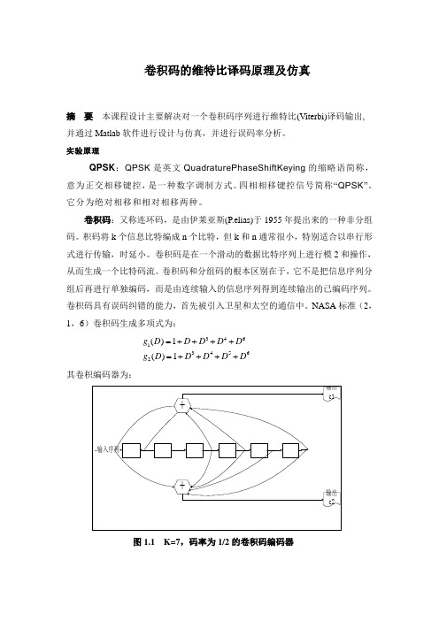
NASA 标准(2,1,6)卷积码生成多项式为: 346134562()1()1g D D D D D g D D D D D=++++=++++其卷积编码器为:图1.1 K=7,码率为1/2的卷积码编码器维特比译码:采用概率译码的基本思想是:把已接收序列与所有可能的发送序列做比较,选择其中码距最小的一个序列作为发送序列。
如果接收到L 组信息比特,每个符号包括v 个比特。
接收到的Lv 比特序列与2L 条路径进行比较,汉明距离最近的那一条路径被选择为最有可能被传输的路劲。
当L 较大时,使得译码器难以实现。
维特比算法则对上述概率译码做了简化,以至成为了一种实用化的概率算法。
它并不是在网格图上一次比较所有可能的2kL 条路径(序列),而是接收一段,计算和比较一段,选择一段最大似然可能的码段,从而达到整个码序列是一个最大似然值得序列。
下面以图2.1的(2,1,3)卷积码编码器所编出的码为例,来说明维特比解码的方法和运作过程。
卷积编码和Viterbi译码
卷积编码和Viterbi译码摘要本文的目的是向读者介绍了前向纠错技术的卷积编码和Viterbi译码。
前向纠错的目的(FEC)的是改善增加了一些精心设计的冗余信息,正在通过信道传输数据的通道容量。
在添加这种冗余信息的过程称为信道编码。
卷积编码和分组编码是两个主要的渠道形式编码。
简介前向纠错的目的(FEC)的是改善增加了一些精心设计的冗余信息,正在通过信道传输数据的通道容量。
在添加这种冗余信息的过程称为信道编码。
卷积编码和分组编码是两个主要的渠道形式编码。
卷积码串行数据操作,一次一个或数位。
分组码操作比较大(通常,多达几百个字节的情侣)消息块。
有很多有用的分组码和卷积多种,以及接收解码算法编码信息的DNA序列来恢复原来的各种数据。
卷积编码和Viterbi译码前向纠错技术,是一种特别适合于在其中一个已损坏的发射信号加性高斯白噪声(AWGN)的主要通道。
你能想到的AWGN信道的噪声,其电压分布也随着时间的推移,可以说是用高斯,或正常,统计分布特征,即一钟形曲线。
这个电压分布具有零均值和标准差这是一个信号与噪声比接收信号的信噪比(SNR)函数。
让我们承担起接收到的信号电平是固定的时刻。
这时如果信噪比高,噪声标准偏差小,反之亦然。
在数字通信,信噪比通常是衡量Eb /N的它代表噪声密度双面能源每比特除以之一。
卷积码通常是描述使用两个参数:码率和约束长度。
码率k/n,是表示为比特数为卷积编码器(十一)信道符号卷积编码器输出的编码器在给定的周期(N)的数量之比。
约束长度参数,钾,表示该卷积编码器的“长度”,即有多少K位阶段提供饲料的组合逻辑,产生输出符号。
K是密切相关的参数米,这表明有多少位的输入编码器周期被保留,用于编码后第一次在卷积编码器输入的出现。
的m参数可以被认为是编码器的记忆长度。
在本教程中,并在此示例的源代码,我集中精力率1 / 2卷积码。
Viterbi译码是一种两个卷积编码与解码,其他类型的算法类型的顺序解码。
matlab卷积编码与viterbi译码的实现

matlab卷积编码与viterbi译码的实现MATLAB中viterbi译码算法讨论⼤家可以再评论区交流!!!MATLAB中实现viterbi译码的函数为:convenc其中:code = convenc(msg,trellis)vitdec其中:vitdec(code,trellis,tblen,opmode,dectype)code卷积编码,trellis⽹格表,tblen回溯长度,opmode:cont、term、trunc,dectype:unquant、hard、soft;本⼈最近在做⼀个关于viterbi译码算法,最终在FPGA中实现,在FPGA中最终的实现⽅案为xillinx IP核实现。
在此之前⽤MATLAB进⾏仿真验证。
matlab程序:Tre = poly2trellis(7,[133 171]);通过poly2trellis⽣成逻辑关系图,如下图所⽰。
逻辑关系图%卷积编码:msg = [0 1 0 1 1 0 1 0 1 1 1 1 0 0 1 1 0 0 1 0 1 0 0 1];code = convenc(msg,Tre);%code = [0,0,1,1,0,1,0,0,0,1,1,0,0,1,0,1,1,0,0,0,1,0,0,0,1,0,1,0,0,1,1,1,1,1,1,1,0,0,1,1,0,1,0,1,1,1,1,0];%这是通过convenc函数⽣成的卷积码%vitdec译码:%在vitdec译码过程中采⽤硬判决,通过不同的tblen和opmode来找出其中关系。
%(1) opmode = conttblen = 12;msg_dat = vitdec(code,Tre,tblen,'cont','hard');%msg_dat =[ 0 0 0 0 0 0 0 0 0 0 0 0 0 1 0 1 1 0 1 0 1 1 1 1 ];%通过了解到cont模式中,vitdec译码会有延迟,延迟的长度为tblen长度,所以在此对vitdec进⾏修改code_temp = [code,zeros(1,24)];msg_temp = vitdec(code_temp ,T,12,'cont','hard')msg_dat = msg_temp(13:end);%msg_dat = [ 0 1 0 1 1 0 1 0 1 1 1 1 0 0 1 1 0 0 1 0 1 0 0 1];%此时vitdec译码出来的数据和信源⼀样tblen = 18;code_temp = [code,zeros(1,24)];msg_temp = vitdec(code_temp ,T,12,'cont','hard')msg_dat = msg_temp(13:end);%msg_dat = [ 0 0 0 0 0 0 0 1 0 1 1 0 1 0 1 1 1 1 0 0 1 1 0 0];%此时vitdec译码出来的数据和信源在后⾯最后⼀位不⼀样%(2) opmode = termtblen = 12;msg_dat = vitdec(code,Tre,tblen,'term','hard');%msg_dat = [0 1 0 1 1 0 1 0 1 1 1 1 0 0 1 1 1 0 0 0 0 0 0 0];%此时vitdec译码出来的数据和信源⼀样前16位和信源⼀样后⾯的就出错了tblen = 18;msg_dat = vitdec(code,Tre,tblen,'term','hard');%msg_dat = [0 1 0 1 1 0 1 0 1 1 1 1 0 0 1 1 1 0 0 0 0 0 0 0];%此时vitdec译码出来的数据和信源⼀样前16位和信源⼀样后⾯的就出错了%(3)opmode = trunctblen = 12;msg_dat = vitdec(code,Tre,tblen,'trunc','hard');%msg_dat = [ 0 1 0 1 1 0 1 0 1 1 1 1 0 0 1 1 0 0 1 0 1 0 0 1];%此时vitdec译码出来的数据和信源⼀样tblen = 18;msg_dat = vitdec(code,Tre,tblen,'trunc','hard');%msg_dat = [ 0 1 0 1 1 0 1 0 1 1 1 1 0 0 1 1 0 0 1 0 1 0 0 1];%此时vitdec译码出来的数据和信源⼀样总结:以上通过⽐较tblen和opmode模式的不同对产⽣的结果,其中cont和trunc的模式总结起来就是cont有tblen延迟,但是trunc没有。
- 1、下载文档前请自行甄别文档内容的完整性,平台不提供额外的编辑、内容补充、找答案等附加服务。
- 2、"仅部分预览"的文档,不可在线预览部分如存在完整性等问题,可反馈申请退款(可完整预览的文档不适用该条件!)。
- 3、如文档侵犯您的权益,请联系客服反馈,我们会尽快为您处理(人工客服工作时间:9:00-18:30)。
卷积编码和Viterbi译码摘要本文的目的是向读者介绍了前向纠错技术的卷积编码和Viterbi译码。
前向纠错的目的(FEC)的是改善增加了一些精心设计的冗余信息,正在通过信道传输数据的通道容量。
在添加这种冗余信息的过程称为信道编码。
卷积编码和分组编码是两个主要的渠道形式编码。
简介前向纠错的目的(FEC)的是改善增加了一些精心设计的冗余信息,正在通过信道传输数据的通道容量。
在添加这种冗余信息的过程称为信道编码。
卷积编码和分组编码是两个主要的渠道形式编码。
卷积码串行数据操作,一次一个或数位。
分组码操作比较大(通常,多达几百个字节的情侣)消息块。
有很多有用的分组码和卷积多种,以及接收解码算法编码信息的DNA序列来恢复原来的各种数据。
卷积编码和Viterbi译码前向纠错技术,是一种特别适合于在其中一个已损坏的发射信号加性高斯白噪声(AWGN)的主要通道。
你能想到的AWGN信道的噪声,其电压分布也随着时间的推移,可以说是用高斯,或正常,统计分布特征,即一钟形曲线。
这个电压分布具有零均值和标准差这是一个信号与噪声比接收信号的信噪比(SNR)函数。
让我们承担起接收到的信号电平是固定的时刻。
这时如果信噪比高,噪声标准偏差小,反之亦然。
在数字通信,信噪比通常是衡量Eb /N的它代表噪声密度双面能源每比特除以之一。
卷积码通常是描述使用两个参数:码率和约束长度。
码率k/n,是表示为比特数为卷积编码器(十一)信道符号卷积编码器输出的编码器在给定的周期(N)的数量之比。
约束长度参数,钾,表示该卷积编码器的“长度”,即有多少K位阶段提供饲料的组合逻辑,产生输出符号。
K是密切相关的参数米,这表明有多少位的输入编码器周期被保留,用于编码后第一次在卷积编码器输入的出现。
的m参数可以被认为是编码器的记忆长度。
在本教程中,并在此示例的源代码,我集中精力率1 / 2卷积码。
Viterbi译码是一种两个卷积编码与解码,其他类型的算法类型的顺序解码。
序贯解码的优点,它可以执行得很好,长期约束卷积码的长度,但它有一个变量解码时间。
维特比解码的优点是它有一个固定的解码时间。
它非常适合于硬件解码器。
但它的计算需求的增长作为约束长度功能指数,因此它是在实践中通常是有限的约束长度的K = 9或更少。
斯坦福大学电信生产的K = 9的Viterbi解码器,速率高达96 Kbps的运作,和K = 7维特比解码器,以高达45 Mbps的操作。
先进的无线技术提供了一个K = 9的Viterbi解码器,速率高达每秒2兆比特运作。
日本NTT公司宣布Viterbi解码器,在60 Mbps的工作,但我不知道它的商业可用性。
摩尔定律适用于维特比解码器,以及微处理器,因此可以考虑提到作为先进设备,在1999年初采取了最先进的快照以上的税率。
多年来,卷积编码和Viterbi译码一直是主要的FEC技术,特别是在地球静止卫星通信网络,如VSAT(甚小孔径终端)网络,在空间通信中使用。
我认为最常见的变异率VSAT网络使用的是1 / 2卷积编码使用约束长度为k = 7的代码。
有了这个代码,可以传送二进制或四相相移键控(BPSK调制或QPSK),至少有5分贝以下的权力比你没有它需要的信号。
这是在瓦,比三因素更能减少!这对于减少发射器和/或天线费用率上升的数据或允许给予同样的发射功率和天线尺寸非常有用。
许多无线电频道AWGN信道,但是很多,尤其是地面广播频道也有其他障碍,如多路径,选择性衰落,干扰和大气(闪电)的噪声。
发射机和接收机的杂散信号,并可以添加到所需的相位噪声信号以及。
虽然卷积编码和Viterbi译码可能会与那些其他问题时非常有用,它未必是最好的技术。
在过去的几年里,卷积编码和Viterbi译码已开始在地球静止卫星通信领域的补充与Reed - Solomon编码。
这两个编码技术通常为串行级联卷积编码块。
通常情况下,要传输的信息进行编码,首先与Reed - Solomon码再与卷积码。
在接收端,维特比解码首先执行,由里德所罗门解码遵循。
这是认为,如果不是用于直接广播卫星(DBS)系统中的所有最,并在较新的甚小孔径终端产品,以及一些技术。
最近(1993年)一个新的并行级联卷积编码技术,作为涡轮编码称为出现了。
初始硬件编码器和解码器的Turbo编码的实现已经出现在市场上。
这种技术实现了级联的Viterbi和Reed - Solomon编码可观的性能改进。
其中一个变种的代码是产品代码也被开发出来,随着硬件实现。
说明算法(第一部分)在模拟通信信道卷积编码和Viterbi使用解码所涉及的步骤如下:(1)生成的数据将通过渠道传播的结果,是二进制数据位。
(2)卷积编码的数据符号的结果是通道。
(3)地图一/零通道符号上一对极基带信号,传输信道的符号生产。
(4)添加噪声的传播通道符号,结果收到的频道符号。
(5)量化接收通道水平,一比特量化称为硬判决,两个量化到N位被称为软判决(N通常三,四)。
(6)维特比译码进行量化上收到的频道符号,结果又是二进制数据位。
(7)比较解码数据位传输的数据位和计算错误的数量。
数据生成生成要发送的数据通过可以通过使用随机数生成器很简单的通道。
用于产生均匀分布的区间数0上,最高值是提供在C:rand ()。
使用这一功能,我们可以说,任何小于最大值的一半是零;任何值大于或等于最大值的一半是另一个。
卷积编码数据卷积编码的数据是通过使用一个移位寄存器和执行相关的组合逻辑模双增加。
(一移位寄存器仅仅是一个连锁触发器,其中第n个触发器的输出是联系在一起的第(n +1)个触发器输入。
每次时钟的有效边沿时,输入在触发器的时钟到输出,因此,数据通过一个阶段的转变。
)的组合逻辑往往是在级联异或门的形式。
作为提醒,异或门的两个输入,一个输出盖茨代表多为如下所示的逻辑符号,实现下面的真值表:异或门实现模其输入双增加。
当您级联Q两输入异或门,与第一次喂养一对的第二个项目投入,产出的第二个食的第三个,等等,一个一个的输入输出输出在链中的最后一个是模双的Q + 1输入的总和。
另一种方式来说明模,两个加法器,而这是最常用的教科书的使用方式,是一个有+符号里面。
现在,我们有两个卷积编码器(触发器组成的移位寄存器和异或门组成的相关模,两个加法器)的定义,让我们看一个卷积编码器的速度1 / 2的图片基本组成部分时,K = 3,m = 2时的代码:在这种编码器,数据位提供了每秒k比特率。
频道符号正处于= 2K的符号每秒施氮量的输出。
输入位编码器中是稳定的周期。
编码器周期开始时,输入时钟边沿发生。
当输入时钟边沿发生时,左边的触发器输出到右边触发器的时钟,上一个输入位移入左侧触发器,一个新的输入位可用。
然后上下模,两个加法器的输出趋于稳定。
输出选择器(sel的的A / B座)循环通过两个国家中的第一个州,它选择并输出上模,两个加法器的输出,在第二个状态,选择及输出的低模输出两个加法器。
上面的编码显示的K = 3,(7,5)卷积码编码器。
八进制数的第7和第5代表的代码生成多项式,当它在读取二进制(1112 1012)对应到移位寄存器的连接上,下模,两个加法器,分别为。
此代码已被确定为费率1 / 2时,K = 3的“最佳”的代码。
这是代码,我会用余下的讨论和例子的原因很明显,这将成为我们进入时,维特比解码算法得到。
让我们来看一个例子输入数据流,以及相应的输出数据流:让输入序列是0101110010100012。
假设的倒装移位寄存器中的触发器输出最初都被清除,即它们的输出是零。
第一个时钟周期,使第一个输入位,零,提供给编码器。
触发器的输出均为零。
该加法器输入到模个都是零,所以编码器的输出为002。
第二个时钟周期,使第二个输入位提供给编码器。
左手在前面一点,这是一个零触发器首饰,钟表及右手按在左手触发器输出零触发器的时钟。
加法器输入到顶部模,两个是1002,因此输出是一个。
加法器的输入模的底部,两个102,因此输出也是一个。
因此,编码器输出11个符号2的通道。
第三个时钟周期,使第三个输入位,一个零,可用于编码器。
左手在前面一点,这是一个触发器的时钟,而右手在零触发器时钟从两个位时代以前。
加法器输入到顶部模,两个是0102,因此输出是一个。
加法器的输入模的底部,两个002,因此输出为零。
因此,编码器输出10符号的通道。
时序图所示说明了此过程:输入后,所有已提交的编码器,输出序列是:00 11 10 00 01 10 01 11 11 10 00 10 11 00 112。
你可以看到从速度1 / 2 = 3的卷积编码器K表结构,由上述每个输入位有符号的三个连续对输出的影响所举的例子。
这是一个非常重要的一点,是什么给了卷积码的纠错能力。
之所以会成为显而易见的,当我们进入维特比解码算法得到的。
现在,如果我们只是要为最后一位传送数据,以上述的15位,影响三种输出符号对,我们需要输出两个符号多对。
这是在我们的例子编码器实现由时钟卷积编码器触发器二(=米)次以上,同时举行为零的投入。
这就是所谓的“冲”的编码器,并在两个以上的输出符号对结果。
最后二进制编码器输出的是这样00 11 10 00 01 10 01 11 11 10 00 10 11 00 11 10 112。
如果我们不执行冲洗操作,邮件的最后一个M 位较少的纠错能力比第一至(m - 1)个位了。
这是一个非常重要的事情要记住,如果你要使用在突发模式环境中,本纠错技术。
So的的清理移位寄存器在每个突发最初的一步。
编码器必须启动一个已知状态解码器能够对输入的数据序列重建在一个已知的正常状态和结束。
现在,让我们来看看从另一个角度编码器。
你可以认为,作为一个简单的状态机的编码器。
这个例子编码器有两个内存位,所以有四种可能的状态。
让我们给左边的触发器2 1二进制重量,而右手触发器2 0二进制重量。
最初,该编码器在全零状态。
如果第一个输入位是零,编码器停留在下一时钟沿在全零状态。
但是,如果输入位为一,编码器转换为在下一个时钟边沿到102的状态。
然后,如果下一个输入位为零,编码器转换为012状态,否则,它转换为112的状态。
下表给出了下一个状态鉴于目前的状态和输入与二进制鉴于国家:上表是通常被称为状态转换表。
我们将引用它作为下一个状态表。
现在让我们看一个表,列出通道输出符号表,鉴于目前的状态和输入数据,我们将称之为输出:你现在应该看到,这两个表,您可以完整地描述了这个例子率1 / 2时,K = 3的卷积编码器的行为。
请注意,这两个表有2(k - 1个)行,2 k列,其中K为约束长度,k为输入数位编码器的周期为每个。
这两个表会派上用场,当我们开始讨论维特比解码算法。
频道符号映射到信号电平对极映射到一个基带信号计划的回旋编码器一/零输出的是一个简单的翻译成0和1 s至1秒的问题。