Project OpenGL 3D Volume-Rendering
基于OpenGL的三维曲面数据场动态显示
基于OpenGL的三维曲面数据场动态显示2007-08-20 08:53作者:白婷赵军朱双华等出处:计算机与信息技术责任编辑:方舟摘要在大数据量条件下,实时动态显示三维曲面较困难,其关键在于提高三维图形数据处理和图形绘制速度。
通过对基于图形工业标准OpenGL实现三维曲面动态显示的原理和方法的讨论,提出采用OpenGL的双缓存、显示列表技术,大幅度提高了图形数据处理和刷新速度,保证了每帧数据图形绘制的连续性和完整性,成功实现了三维曲面数据场实时动态显示。
关键词OpenGL 三维曲面动态显示引言在某三维数据场中,数据随时间的变化而发生变化,为直观观察数据随时间变化的态势,需对数据场的变化实时动态显示。
利用网格曲面显示三维数据场是一种直观的方法,但需经过数据插值、投影、曲面拼接、消隐等处理后方可绘制图形,计算量较大。
在数据量较大的情况下,实时动态显示三维曲面图形较困难,其关键在于提高每帧图形处理和绘制刷新速度,以保证每帧三维曲面显示时的连贯性和完整性。
OpenGL是性能卓越的图形处理工具,采用OpenGL双缓存和绘图操作予编译技术,较好解决了三维图形数据处理和绘图刷新速度问题。
利用Visual C++调用OpenGL的三维图形编程接口成功实现了大数据量的三维曲面图形的实时动态显示。
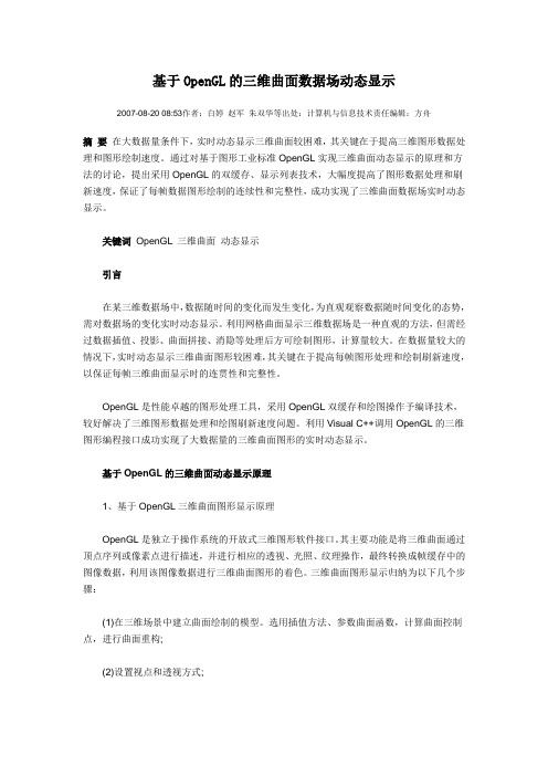
基于OpenGL的三维曲面动态显示原理1、基于OpenGL三维曲面图形显示原理OpenGL是独立于操作系统的开放式三维图形软件接口。
其主要功能是将三维曲面通过顶点序列或像素点进行描述,并进行相应的透视、光照、纹理操作,最终转换成帧缓存中的图像数据,利用该图像数据进行三维曲面图形的着色。
三维曲面图形显示归纳为以下几个步骤:(1)在三维场景中建立曲面绘制的模型。
选用插值方法、参数曲面函数,计算曲面控制点,进行曲面重构;(2)设置视点和透视方式;(3)进行消隐、光照、纹理、明暗处理;(4)绘制场景,输出到屏幕窗口。
图1 三维曲面图形显示基本流程2、利用双缓存实现动态显示原理三维曲面动态显示需要连续地绘制三维曲面并显示场景,用不同的曲面数据刷新屏幕视窗。
OpenGL教程

OpenGL教程在这个系列讲座中介绍了有关OpenGL的基本知识,主要涉及颜色、绘制几何体、坐标变换、堆栈操作、显示列表、光照和材质、纹理映射、特殊效果、曲面和曲线的绘制、二次几何体绘制、像素操作、如何绘制动画物体及菜单管理。
通过对讲座中提供的实例的理解消化,读者可以较容易地进入OpenGL的世界。
第一讲基本概念前言随着计算机多媒体技术、可视化技术及图形学技术的发展,我们可以使用计算机来精确地再现现实世界中的绚丽多彩的三维物体,并充分发挥自身的创造性思维,通过人机交互来模拟、改造现实世界,这就是目前最为时髦的虚拟现实技术。
通过这种技术,建筑工程师可以直接设计出美观的楼房模型;军事指挥员可以模拟战场进行军事推演,网民可以足不出户游览故宫博物馆等名胜古迹等。
而虚拟现实技术最重要的一部分内容就是三维图形编程。
当前,三维图形编程工具中最为突出的是SGI公司的OpenGL(Open Graphics Language,开放式的图形语言),它已经成为一个工业标准的计算机三维图形软件开发接口,并广泛应用于游戏开发、建筑、产品设计、医学、地球科学、流体力学等领域。
值得一提的是,虽然微软有自己的三维编程开发工具DirectX,但它也提供OpenGL图形标准,因此,OpenGL可以在微机中广泛应用。
目前,OpenGL在国内外都掀起了热潮,但国内对这一领域介绍的资料并不是很多,特别是有志于在图形图像方面进行深入研究的读者朋友,常常苦于不掌握OpenGL编程接口技术,无法向纵深领域扩展。
为了开启三维图形编程这扇神秘大门,本讲座在结合OpenGL有关理论知识的基础上,着重介绍Visual C++6.0开发环境中的编程实现,由于水平有限,本讲座可能无法面面俱到,存在一些疏漏,但相信它可以将开启"神秘大门"的钥匙交给读者朋友们。
一、OpenGL的特点及功能OpenGL是用于开发简捷的交互式二维和三维图形应用程序的最佳环境,任何高性能的图形应用程序,从3D动画、CAD辅助设计到可视化访真,都可以利用OpenGL高质量、高性能的特点。
常用的图形库
ESRI
PCI Geomatics
Digital Grove
JDMCox Global Mapper Software(USAPhotoMaps) 3DEM
MARPLOT
Map Maker
OCAD
SurGe
3D Contour Maps
geoTIFF Examiner
shapechk
GeoMerge
Relief Texture Mapping
Graphics:Non-Photo-Realistic Rendering(NPR)
NPR
Shadows for Cel Animation
David Salesin
Virtual Clay: A Deformation NPRQuake Model by 3D Cellular Automata
GRAIL: Graphics and Imaging Laboratory
Microsoft Research: UCSC SciVis Graphics
Visualization Lab SUNY at Stony VRVis Brook, New York
Institut of Computer Graphics and Algorithms
tiff library
Independent JPEG Group
FFTW
paintlib
png library
libungif
Gnuplot
Interactive Data ImageMagick Language(IDL) Matlab
IPL98
CVIPtools
Cppima
Open Source Computer VXL Vision Library JBIG-KIT
实时渲染中几种 Rendering Path 的技术基础

实时渲染中几种Rendering Path 的技术基础1. rendering path 的技术基础在介绍各种光照渲染方式之前,首先必须介绍一下现代的图形渲染管线。
这是下面提到的几种Rendering Path 的技术基础。
目前主流的游戏和图形渲染引擎,包括底层的API(如DirectX 和OpenGL)都开始支持现代的图形渲染管线。
现代的渲染管线也称为可编程管线(Programmable Pipeline),简单点说就是将以前固定管线写死的部分(比如顶点的处理,像素颜色的处理等等)变成在GPU上可以进行用户自定义编程的部分,好处就是用户可以自由发挥的空间增大,缺点就是必须用户自己实现很多功能。
下面简单介绍下可编程管线的流程。
以OpenGL 绘制一个三角形举例。
首先用户指定三个顶点传给Vertex Shader。
然后用户可以选择是否进行Tessellation Shader(曲面细分可能会用到)和Geometry Shader(可以在GPU 上增删几何信息)。
紧接着进行光栅化,再将光栅化后的结果传给Fragment Shader 进行pixel 级别的处理。
最后将处理的像素传给FrameBuffer 并显示到屏幕上。
2. 几种常用的Rendering PathRendering Path 其实指的就是渲染场景中光照的方式。
由于场景中的光源可能很多,甚至是动态的光源。
所以怎么在速度和效果上达到一个最好的结果确实很困难。
以当今的显卡发展为契机,人们才衍生出了这么多的Rendering Path 来处理各种光照。
2.1 Forward RenderingForward Rendering 是绝大数引擎都含有的一种渲染方式。
要使用Forward Rendering,一般在Vertex Shader 或Fragment Shader 阶段对每个顶点或每个像素进行光照计算,并且是对每个光源进行计算产生最终结果。
OpenGL绘图 简单3D空间 3D漫游的实现

主要参考了NEHE的Opengl教程所有物体都是直接用代码画的,没有经过建模。
主要部分有详细注释。
适合刚接触图形学或OpenGL的新手。
老鸟勿来。
部分效果图:全部代码,VC6.0环境:/*主要实现简单的3D空间搭建,添加物体旋转效果,光照,纹理映射,3D漫游,雾化效果*/#include <windows.h>// Header File For Windows#include <math.h>// Math Library Header File#include <stdio.h>// Header File For Standard Input/Output#include <gl\gl.h>// Header File For The OpenGL32 Library#include <gl\glu.h>// Header File For The GLu32 Library#include <gl\glaux.h>// Header File For The Glaux LibraryHDC hDC=NULL;// Private GDI Device ContextHGLRC hRC=NULL;// Permanent Rendering ContextHWND hWnd=NULL;// Holds Our Window HandleHINSTANCE hInstance;// Holds The Instance Of The Applicationbool keys[256];// Array Used For The Keyboard Routinebool active=TRUE;// Window Active Flag Set To TRUE By Defaultbool fullscreen=TRUE;// Fullscreen Flag Set To Fullscreen Mode By Defaultbool blend;// Blending ON/OFFbool bp;// B Pressed?bool fp;// F Pressed?bool gp;// G Pressed?bool light;bool lp;GLuint fogMode[]= { GL_EXP, GL_EXP2, GL_LINEAR };// 雾气的三种模式GLuint fogfilter = 0;// Which Fog Mode To UseGLfloat fogColor[4] = {0.5f,0.5f,0.5f,1.0f};// Fog ColorGLfloat walkbias = 0;GLfloat walkbiasangle = 0;GLfloat lookupdown = 0.0f;float x;float z;GLfloat eye[]={0.0f,0.0f,0.0f};GLfloat lookat[]={0.0f,0.0f,0.0f};GLfloat angle=-90.0;GLfloat speed=0.5;float PI=3.14159f;GLuint filter;// Which Filter To UseGLuint texture[7];// 储存7个纹理LRESULT CALLBACK WndProc(HWND, UINT, WPARAM, LPARAM);// Declaration For WndProcAUX_RGBImageRec *LoadBMP(char *Filename) // 加载一个位图{FILE *File=NULL; // File Handleif (!Filename) // Make Sure A Filename Was Given{return NULL; // If Not Return NULL }File=fopen(Filename,"r"); // Check To See If The File Existsif (File) // Does The File Exist?{fclose(File); // Close The Handlereturn auxDIBImageLoad(Filename); // Load The Bitmap And Return A Pointer}return NULL; // If Load Failed Return NULL }int LoadGLTextures() // 加载位图并将其转化为纹理{int Status=FALSE; // Status IndicatorAUX_RGBImageRec *TextureImage[1]; // Create Storage Space For The Texturememset(TextureImage,0,sizeof(void *)*1); // Set The Pointer To NULLif (TextureImage[0]=LoadBMP("Data/zhou.bmp")) //指定风扇轴的纹理{Status=TRUE; // Set The Status To TRUEglGenTextures(1, &texture[0]);glBindTexture(GL_TEXTURE_2D,texture[0]);glTexImage2D(GL_TEXTURE_2D,0,3,TextureImage[0]->sizeX,TextureImage[0]->sizeY,0,GL_RGB,GL_ UNSIGNED_BYTE,TextureImage[0]->data);glTexParameteri(GL_TEXTURE_2D,GL_TEXTURE_MIN_FILTER,GL_LINEAR);glTexParameteri(GL_TEXTURE_2D,GL_TEXTURE_MAG_FILTER,GL_LINEAR);}if(TextureImage[0]=LoadBMP("Data/yepian.bmp")) //指定风扇叶的纹理{Status=TRUE;glGenTextures(1,&texture[1]);glBindTexture(GL_TEXTURE_2D,texture[1]);glTexImage2D(GL_TEXTURE_2D,0,3,TextureImage[0]->sizeX,TextureImage[0]->sizeY,0,GL_RGB,GL_ UNSIGNED_BYTE,TextureImage[0]->data);glTexParameteri(GL_TEXTURE_2D,GL_TEXTURE_MIN_FILTER,GL_LINEAR);glTexParameteri(GL_TEXTURE_2D,GL_TEXTURE_MAG_FILTER,GL_LINEAR);}if(TextureImage[0]=LoadBMP("Data/qiang.bmp")) //指定左右墙壁的纹理{Status=TRUE;glGenTextures(1,&texture[2]);glBindTexture(GL_TEXTURE_2D,texture[2]);glTexImage2D(GL_TEXTURE_2D,0,3,TextureImage[0]->sizeX,TextureImage[0]->sizeY,0,GL_RGB,GL_ UNSIGNED_BYTE,TextureImage[0]->data);glTexParameteri(GL_TEXTURE_2D,GL_TEXTURE_MIN_FILTER,GL_LINEAR);glTexParameteri(GL_TEXTURE_2D,GL_TEXTURE_MAG_FILTER,GL_LINEAR);}if(TextureImage[0]=LoadBMP("Data/diban.bmp")) //指定地板的纹理{Status=TRUE;glGenTextures(1,&texture[3]);glBindTexture(GL_TEXTURE_2D,texture[3]);glTexImage2D(GL_TEXTURE_2D,0,3,TextureImage[0]->sizeX,TextureImage[0]->sizeY,0,GL_RGB,GL_ UNSIGNED_BYTE,TextureImage[0]->data);glTexParameteri(GL_TEXTURE_2D,GL_TEXTURE_MIN_FILTER,GL_LINEAR);glTexParameteri(GL_TEXTURE_2D,GL_TEXTURE_MAG_FILTER,GL_LINEAR);}if(TextureImage[0]=LoadBMP("Data/tianhuaban.bmp")) //指定天花板的纹理{Status=TRUE;glGenTextures(1,&texture[4]);glBindTexture(GL_TEXTURE_2D,texture[4]);glTexImage2D(GL_TEXTURE_2D,0,3,TextureImage[0]->sizeX,TextureImage[0]->sizeY,0,GL_RGB,GL_ UNSIGNED_BYTE,TextureImage[0]->data);glTexParameteri(GL_TEXTURE_2D,GL_TEXTURE_MIN_FILTER,GL_LINEAR);glTexParameteri(GL_TEXTURE_2D,GL_TEXTURE_MAG_FILTER,GL_LINEAR);}if(TextureImage[0]=LoadBMP("Data/qiang2.bmp")) //指定对面墙的纹理{Status=TRUE;glGenTextures(1,&texture[5]);glBindTexture(GL_TEXTURE_2D,texture[5]);glTexImage2D(GL_TEXTURE_2D,0,3,TextureImage[0]->sizeX,TextureImage[0]->sizeY,0,GL_RGB,GL_ UNSIGNED_BYTE,TextureImage[0]->data);glTexParameteri(GL_TEXTURE_2D,GL_TEXTURE_MIN_FILTER,GL_LINEAR);glTexParameteri(GL_TEXTURE_2D,GL_TEXTURE_MAG_FILTER,GL_LINEAR);}if(TextureImage[0]=LoadBMP("Data/shafa.bmp")) //指定沙发的纹理{Status=TRUE;glGenTextures(1,&texture[6]);glBindTexture(GL_TEXTURE_2D,texture[6]);glTexImage2D(GL_TEXTURE_2D,0,3,TextureImage[0]->sizeX,TextureImage[0]->sizeY,0,GL_RGB,GL_ UNSIGNED_BYTE,TextureImage[0]->data);glTexParameteri(GL_TEXTURE_2D,GL_TEXTURE_MIN_FILTER,GL_LINEAR);glTexParameteri(GL_TEXTURE_2D,GL_TEXTURE_MAG_FILTER,GL_LINEAR);}if (TextureImage[0]) // If Texture Exists{if (TextureImage[0]->data) // If Texture Image Exists{free(TextureImage[0]->data); // Free The Texture Image Memory}free(TextureImage[0]); // Free The Image Structure }return Status; // Return The Status}GLvoid ReSizeGLScene(GLsizei width, GLsizei height)// Resize And Initialize The GLWindow{if (height==0)// Prevent A Divide By Zero By {height=1;// Making Height Equal One }glViewport(0,0,width,height);// Reset The Current ViewportglMatrixMode(GL_PROJECTION);// Select The Projection Matrix glLoadIdentity();// Reset The Projection Matrix// Calculate The Aspect Ratio Of The WindowgluPerspective(45.0f,(GLfloat)width/(GLfloat)height,0.1f,120.0f);glMatrixMode(GL_MODELVIEW);// Select The Modelview MatrixglLoadIdentity();// Reset The Modelview Matrix }//设置0—6号光源位置GLfloat sun_light_position0[] = {0.0f, -5.0f, 2.0f, 1.0f};GLfloat sun_light_position1[] = {0.0f, 7.0f, 2.0f, 1.0f};GLfloat sun_light_position2[] = {-10.0f, -5.0f, -30.0f, 1.0f};GLfloat sun_light_position3[] = {10.0f, 7.0f, -30.0f, 1.0f};GLfloat sun_light_position4[] = {10.0f, 5.0f, -50.0f, 1.0f};GLfloat sun_light_position5[] = {-10.0f, -5.0f, -50.0f, 1.0f};GLfloat sun_light_ambient[] = {0.5f, 0.5f, 0.5f, 1.0f}; //环境光GLfloat sun_light_diffuse[] = {1.0f, 1.0f, 1.0f, 1.0f}; //漫射光GLfloat sun_light_specular[] = {1.0f, 1.0f, 1.0f, 1.0f}; //反射光int InitGL(GLvoid)// 开始对OpenGL进行所有的设置{if (!LoadGLTextures())// Jump To Texture Loading Routine{return FALSE;// If Texture Didn't Load Return FALSE}glEnable(GL_TEXTURE_2D);// 开启纹理映射glBlendFunc(GL_SRC_ALPHA,GL_ONE);// Set The Blending Function For TranslucencyglClearColor(0.0f, 0.0f, 0.0f, 0.0f);// 清理背景颜色为黑色glClearDepth(1.0);// 开启清理深度缓存glHint(GL_PERSPECTIVE_CORRECTION_HINT,GL_NICEST); //透视修正glLightfv(GL_LIGHT0, GL_POSITION, sun_light_position0); //0号光源glLightfv(GL_LIGHT0, GL_AMBIENT, sun_light_ambient);glLightfv(GL_LIGHT0, GL_DIFFUSE, sun_light_diffuse);glLightfv(GL_LIGHT0, GL_SPECULAR, sun_light_specular);glLightfv(GL_LIGHT1, GL_POSITION, sun_light_position1); //1号光源glLightfv(GL_LIGHT1, GL_AMBIENT, sun_light_ambient);glLightfv(GL_LIGHT1, GL_DIFFUSE, sun_light_diffuse);glLightfv(GL_LIGHT1, GL_SPECULAR, sun_light_specular);glLightfv(GL_LIGHT2, GL_POSITION, sun_light_position2); //2号光源glLightfv(GL_LIGHT2, GL_AMBIENT, sun_light_ambient);glLightfv(GL_LIGHT2, GL_DIFFUSE, sun_light_diffuse);glLightfv(GL_LIGHT2, GL_SPECULAR, sun_light_specular);glLightfv(GL_LIGHT3, GL_POSITION, sun_light_position3); //3号光源glLightfv(GL_LIGHT3, GL_AMBIENT, sun_light_ambient);glLightfv(GL_LIGHT3, GL_DIFFUSE, sun_light_diffuse);glLightfv(GL_LIGHT3, GL_SPECULAR, sun_light_specular);glLightfv(GL_LIGHT4, GL_POSITION, sun_light_position4); //4号光源glLightfv(GL_LIGHT4, GL_AMBIENT, sun_light_ambient);glLightfv(GL_LIGHT4, GL_DIFFUSE, sun_light_diffuse);glLightfv(GL_LIGHT4, GL_SPECULAR, sun_light_specular);glLightfv(GL_LIGHT5, GL_POSITION, sun_light_position5); //5号光源glLightfv(GL_LIGHT5, GL_AMBIENT, sun_light_ambient);glLightfv(GL_LIGHT5, GL_DIFFUSE, sun_light_diffuse);glLightfv(GL_LIGHT5, GL_SPECULAR, sun_light_specular);glEnable(GL_LIGHTING); //启用光源glEnable(GL_LIGHT0); //启用0号光源glEnable(GL_LIGHT1); //启用1号光源glEnable(GL_LIGHT2);glEnable(GL_LIGHT3);glEnable(GL_LIGHT4);glEnable(GL_LIGHT5);glFogi(GL_FOG_MODE, fogMode[fogfilter]);// Fog ModeglFogfv(GL_FOG_COLOR, fogColor);// Set Fog ColorglFogf(GL_FOG_DENSITY, 0.1f);// 雾气的浓度glHint(GL_FOG_HINT, GL_DONT_CARE);// 系统如何计算雾气glFogf(GL_FOG_START, -10.0f);// 雾气的开始位置glFogf(GL_FOG_END, -58.0f);// 雾气的结束位置glEnable(GL_FOG);return TRUE;// Initialization Went OK}void DrawGLfengshanzhou() //画一个四边形作为风扇轴{glBindTexture(GL_TEXTURE_2D, texture[0]); //绑定0号纹理,即风扇轴的纹理glBegin(GL_QUADS); //画四边形glNormal3f( 0.0f, 0.0f, 1.0f); //设置法向量glTexCoord2f(0.0f, 0.0f); glVertex3f(-0.1f, -2.5f, 0.0f); //纹理和四边形左下坐标glTexCoord2f(1.0f, 0.0f); glVertex3f( 0.1f, -2.5f, 0.0f); //纹理和四边形右下坐标glTexCoord2f(1.0f, 1.0f); glVertex3f( 0.1f, 2.5f, 0.0f); //纹理和四边形右上坐标glTexCoord2f(0.0f, 1.0f); glVertex3f(-0.1f, 2.5f, 0.0f); //纹理和四边形左上坐标glEnd();}void DrawGLfengshanye() //画一个四边形作为风扇叶片{glBindTexture(GL_TEXTURE_2D, texture[1]); //绑定1号纹理,即叶片的纹理glBegin(GL_QUADS);glNormal3f(0.0f,1.0f,0.0f);glTexCoord2f(0.0f, 0.0f);glVertex3f( 4.0f, 0.0f, 1.0f);glTexCoord2f(1.0f, 0.0f);glVertex3f(-4.0f, 0.0f, 1.0f);glTexCoord2f(1.0f, 1.0f);glVertex3f(-4.0f, 0.0f, -1.0f);glTexCoord2f(0.0f, 1.0f);glVertex3f( 4.0f, 0.0f, -1.0f);glEnd();}void DrawGLfengshan(GLfloat x) //画风扇,由柱和叶片组合而成,有一个浮点型参数,代表旋转增量{glPushMatrix();glTranslatef(0.0,2.5f,0.0); //轴长5.0,开始在中心原点,所以先向上平移2.5DrawGLfengshanzhou(); //画风扇轴glPopMatrix();glPushMatrix();glRotatef(x,0.0f,1.0f,0.0f); //使风扇叶片绕Y轴旋转,x表示旋转增量glPushMatrix();glTranslatef(4.0f,0.0f,0.0f); //风扇叶长8.0,开始在中心原点,所以先向右平移4.0DrawGLfengshanye(); //画第一个叶片glPopMatrix();glPushMatrix();glRotatef(120,0.0f,1.0f,0.0f); //旋转120度glTranslatef(4.0f,0.0f,0.0f); //注意:编码时变换的顺序和实际变换的顺序刚好相反。
volume shader 原理

volume shader 原理Volume Shader原理Volume shader是一种在计算机图形学中用于模拟体积材质的渲染技术。
它能够模拟各种各样的体积效果,例如云彩、烟雾、水汽等,使得场景更加逼真。
在本文中,我将详细介绍Volume Shader的原理,从渲染管线开始,一步一步回答问题。
1. 渲染管线在理解Volume Shader原理之前,我们需要先了解计算机图形学中的渲染管线。
渲染管线是一个图形渲染的过程,也可以称为图形加工流水线。
它通常包含几个阶段,包括顶点处理、光栅化、片元处理等。
在Volume Shader中,片元处理阶段是最重要的。
2. 体积数据表示体积数据表示了一个三维空间中的密度分布。
对于体积渲染来说,最常用的表示方法是体素化。
体素是三维空间中的一个点,类似于二维图像中的像素。
通过将整个空间划分成一个个立方体,然后在每个立方体内存储一个数值,可以表示出三维空间的密度分布。
3. 光传播模型在体积渲染中,我们需要模拟光在物质内的传播方式。
常用的光传播模型包括蒙特卡洛积分、基于物理的光传播等。
蒙特卡洛积分是模拟随机采样的方法,通过在体素内进行随机采样来模拟光的传播。
基于物理的光传播则是基于光的吸收、散射和发射等物理过程来模拟光的传播。
4. 散射模型散射是体积材质中的重要现象,它可以导致光的随机偏转。
常见的散射模型包括Isotropic散射、Henzy-Greenstein散射等。
Isotropic散射是一种各向同性的散射模型,它认为光在任何方向上的散射概率是相同的。
Henzy-Greenstein散射则是基于统计学原理来模拟散射方向的随机性。
5. 吸收模型吸收是体积材质中的另一个重要现象,它导致光的能量逐渐减弱。
吸收模型通常使用吸收系数来描述吸收强度。
吸收系数越大,表示材质吸收光的强度越大。
6. 渲染算法在Volume Shader中,渲染算法主要用于计算光线与体积材质的相互作用。
OpenGL简介
OpenGL简介(),Open Graphics Library,开放图形库,是跨语⾔、跨平台的3D图形编程接⼝。
OpenGL使⽤客户端 - 服务器架构设计,应⽤程序为客户端,图形硬件设备为服务器。
客户端负责提交OpenGL命令,服务器执⾏这些命令并渲染出图像。
OpenGL是⼀个状态机,每个状态都有⼀个默认值。
开发者可以设置这些状态,然后让它们⼀直⽣效,直到再次修改它们。
例如:当前颜⾊就是⼀个状态变量,可以把其设置成红⾊,那么在此之后绘制的所有物体都会使⽤这种颜⾊,直到再次把当前颜⾊设置为其他颜⾊。
OpenGL的API可通过软件模拟实现,⾼效实现依赖于显⽰设备⼚商提供的硬件加速。
注:开源()是⼀个纯软件模拟实现的图形API,其代码兼容于OpenGL。
OpenGL规范⽬前由⾮盈利组织()的架构评审委员会(Architecture Review Board,ARB)维护。
ARB主要由操作系统⼚商(Apple Computer、Microsoft【2003.3已退出】等)、图形硬件⼚商(3Dlabs、SGI、NVIDIA、ATI Technologies、Intel等)、技术公司(Mozilla、Google等)和国际3D组织组成。
OpenGL是⼀个不断进化的API,在OpenGL1.2.1版本引⼊扩展(extension)的概念。
OpenGL新版本会定期由Khronos Group发布。
①增加新的扩展API(引⼊新函数和新常量)来增加新功能②放松或取消现有扩展API的限制来增强功能⼀个扩展由两部分组成:包含扩展函数原型的头⽂件和⼚商的设备驱动实现ARB扩展:标准扩展。
由架构评审委员ARB批准发布。
第⼀个ARB扩展是GL_ARB_multitexture(注:在OpenGL1.3中加⼊)。
所有ARB 扩展可从查询。
GL_ARB_multitexture扩展中新增了包含glActiveTextureARB、glClientActiveTextureARB、glMultiTexCoord*ARB函数,共34个。
主流3d引擎操作方法
主流3d引擎操作方法主流的3D游戏引擎有Unity和Unreal Engine。
以下是这两个引擎的一些基本操作方法:Unity引擎:1. 创建新项目:打开Unity,点击"New"按钮,选择项目的名称和位置,然后点击"Create Project"。
2. 导入模型:将你的3D模型文件拖放到Unity的Project视图中,或者右键点击Project视图中的文件夹,选择"Import New Asset",然后选择你的模型文件。
3. 创建场景:在Unity的Hierarchy视图中,右键点击空白处,选择"Create Empty"来创建一个空对象。
拖动模型到场景视图中,将其放置在适当的位置。
4. 添加组件:在Inspector视图中,选择你的对象,然后点击"Add Component"来添加各种组件,比如碰撞器、动画控制器等。
5. 脚本编程:在Unity中使用C#编写脚本。
在Project视图中,右键点击文件夹,选择"Create"->"C# Script"来创建一个新的脚本。
然后将脚本附加到对象上,并使用脚本来控制对象的行为。
6. 调试与运行:点击Unity的播放按钮或者按下Ctrl+P来运行你的游戏。
你可以在运行时进行调试,通过Unity的控制台查看输出日志,并在需要时进行修改和调整。
Unreal Engine引擎:1. 创建新项目:打开Unreal Engine,点击"New Project",选择项目的名称和位置,然后点击"Create Project"。
2. 导入模型:将你的3D模型文件拖放到Unreal Engine的Content Browser 中,或者右键点击Content Browser的文件夹,选择"Import",然后选择你的模型文件。
Web3D展示解决方案:基于WebGL和HTML5的3D网络展示技术说明书
M.J. Bian
School of Computer Engineering and Science Shanghai University Shanghai, China
H.H. Gao
Computer Center Shanghai University
Shanghai, CБайду номын сангаасina
J. Gao
Keywords- Web3D; virtual reality; WebGL; Html5; digital museum
I. INTRODUCTION
A. Web3D Current Situation
Web3D technology can be traced back to the VRML (Virtual Reality Modeling Language). In 1998, VRML Association completed the conversion from VRML to Extensible 3D (Extensible 3D Language) and was renamed Web3D Consortium. It was the first time that the word Web3D being used [1]. Many famous organizations have launched their own the web3D technologies, such as Cycore’s Cult3D, Sun Microsystems’s Java3D and so on. However, Web3D still have many problems, such as low rendering efficiency, poor compatibility, need to plug-in and so on. Each Web3D technology has its own characteristics and advantages, the competition will exist for a long time.
三维虚拟空间技术(OpenGL)在工程实体形象进度中的应用
小, 可用四维齐次坐标 [ z1来表示 三维空 间的一 XY ] 点[ z , x ]经变换后 的坐标为 [’’ Y xYz 。 ’o假设 ab c 。 、、 分
别表示为 x Y z 方 向上进行 比例 变换 时 的 比例 系 、、 轴
维普资讯
Y n忙 日
中 南 水 力发 电
第1 期
一 I I一J 术 、 p “ L 三维 虚 空 间技 ’ O-n , I l , J 拟 - i( . G ) J ^ V, V u e 在 工 程 实体 形 象 进 度 中 的应 用
r 一. -… . L
11 1J =
r … . 一 11 L 1J
0 l
n
b 0
n
0 c
n
0 0
'
U
U
U
工
12 错 切 变换 . 三维 错切 变 换 是使 空 间 中 的三 维 图形 沿 xYz 、 、 三
个方向产生错 切 , 如果用 d e 、 表示为 X 方向的错切系
上, 方法之一是采用将 空间点投影 到平 面的方 法来 实 现。而这些投影 , 是通过三维 图形变换来实现的。
1 1
1 ・ 1
1拓 I . l 锄匿
p0 . , 品 7
三维 图形 可 以 在 各 个 坐 标 方 向 上 进 行 放 大 或 缩
用 网络技术 , 现有的三维 图形软件 几乎是不可能做到 与网络进度软件通讯 , 也很难进行程序控制 。
戴 光 华 谢 少权 何 湘如 王 志 刚
( 中南勘 测设 计研 究 院 , 南 长 沙 40 1) 湖 104
- 1、下载文档前请自行甄别文档内容的完整性,平台不提供额外的编辑、内容补充、找答案等附加服务。
- 2、"仅部分预览"的文档,不可在线预览部分如存在完整性等问题,可反馈申请退款(可完整预览的文档不适用该条件!)。
- 3、如文档侵犯您的权益,请联系客服反馈,我们会尽快为您处理(人工客服工作时间:9:00-18:30)。
Project: Real-time 3D Rendering Engine (RT3D)1. Main Goal:To develop a backbone 3D volume rendering code, using OpenGL/DirectX capabilities (such as textures) for interactive 3D medical imaging.2. What we are looking forThis project should produce the images comparable with the following examples: /gallery/med_gallery.html3. Project design3.1. Input dataRT3D should take as an input a series of images (as pixel buffers). Each imagecorresponds to a 3D volume slice, so the series corresponds to a 3D volume (all slices are parallel and equidistant).Position of the viewer, rendering plane, etc. should be supplied to define the rendering direction and any other required parameters.3.2.Output RT3D should output the rendered image as a pixel buffer. I.e., RT3D must not render anything on the screen– all rendering must be done completely offscreen . In essence, RT3D should function as a totally separate, GUI-independent image renderer, using the power of OpenGL (or DirectX, and anything else you may suggest) to achieve real-time rendering speeds3.3. Coding1.RT3D should be implemented in Visual Studio 2005, in C++ (unmanaged), as aset of separate classes.2.RT3D has to support 2 different rendering speeds;a.Fast – to achieve at least 20 frames (renderings) per second, so that usercan render images interactively. For large data volumes, you will have torender at lower resolution to support interactive speedb.Slow – high-quality (full-resolution) rendering3.The following rendering types should be included in your implementation:a.Planar – simple planar cut through the volumeb.Thick slice –planar slice with given “thickness”c.MaxIP, minIP – maximum and minimum intensity projectionsImagine that you have rendered the volume at some angle, and created a series of parallel images (planar renderings). Than any one of these images is you planar rendering, thick slice can be obtained as their weighted average, MaxIP – as their maximum (at each pixel), minIP – as their minimum (at each pixel). I.e., any rendering type in this project can be derived from 3a, planar rendering.3.4. Project implementation stagesWe will ask you to do the following:1.Write a sample app which takes a series of bitmap images from a given folder,and interactively renders a slice image in a user-defined plane. Note that yourrendering should be implemented as offscreen – i.e., you render into a pixel buffer first, and then you display the buffer.2.If successful, port this into our application code3.Add thick slice, MaxIP and minIP rendering types.3.5. BonusesIf successful, this project will be taken to the next stage, to implement:1.Curved-planar renderings: instead of “cutting” the volume with a plane, you c ut itwith a predefined surface, and create the resulting cut image2.Graphics-card-specific optimizations. For instance, using nVidia-specificrendering capabilities to enhance the original card-independent rendering.3.Surface rendering – render iso-surface for a given intensity range [i0, i1]Keep these extensions in mind when you implement your basic code, so that you can add them later easily.4. Performance requirements1.There are tons of 3D renderers available online, open-source, and we already haveour own code, so making 3D images is not the main point of the project. The main point is to do it real-time, and with the highest quality possible. Our data will belarge: on average, we are talking about 1000-4000 images in a single series(volume), 512x512 pixels each image. I.e., your original volume will have2000x512x512 voxels, and this is what you will have to render to create 3Dreconstructions.2.The program will be used by many clients, on whatever hardware they have. I.e.,the RT3D should work on virtually any current (Windows) PC. RT3D must firstdetect the system capabilities (graphics card type, memory, support forOpenGL/DirectX), and then eitherrm the user that his computer cannot be used for this rendering,because it lacks certain hardware. These occasions should be absolutelyminimized. ORb.Render the images. If the hardware is slow, then more resolution may becompromised (reduced) in the fast-rendering mode, just to make it run onthis PC. But the final image should always be produced with the finestquality (i.e., with the same resolution, as the original images –for instance,512x512 pixels)So, process any data size interactively, and work on virtually any Windows PC are two main requirements for this implementation. For instance, the project can be easily done with 3D textures, but what if they are not supported on the target PC?5. Data formatOur input images are bitmaps of any bit depth, up to 16 bits per color channel. Practically, there will be 2 sorts of images:1.Grayscale images, with 16-bit grayscale (from 0 to 65535). More likely, we willconvert them into either color or 8-bit grayscale2.Color RGB images (8-bit color per channel, i.e, regular 24-bit bitmaps) Therefore, RT3D should support at least 2 voxel color formats: 8-bit grayscale and 24-bit color (RGB). Then, to render grayscale images, you won’t have to allocate too much memory.Also, each image series will have its own physical voxel size – for instance, a voxel would correspond to a [1mm x 0.45mm x 0.45mm]. So RT3D will have to accommodate these voxel proportions to display voxels with their natural dimensions.6. Test dataWe will provide you with the real image series to test.7. Developers we are looking forThis is not a learning project. We need someone with very solid experience in the 3D image rendering. The above project description should be sufficient for you, and youshould be able to implement any specific details and optimizations on your own. Your work will be judged only by its final result, and it will not be accepted if it fails to achieve what we described. On the other side, if it works as expected, we will have more 3D projects to come. This is a very interesting area, and we would like to find someone experienced and creative to work with us on 3D projects.To be considered for this project, do not send us your generic “plug and play” resume. Instead, please provide us with a description and a sample of your related work. Ideally, some sample interactive 3D-renderer or shader app, which we could run.。