
外文翻译原文
Communication PLC with Embedded systemsDUSAN HAVLIKDepartment of Control EngineeringCTU in Prague, FEEKarlovo namesti 13, 121 35 Prague 2CZECH REPUBLICAbstract: This paper presents communication PLC and embedded systems. The paper presents centra-lized and decentralized network between PLC and embedded systems. Communication PLC and embedded systems is dependent on structure of network and is type master - slave. In the end of the paper is connection between PLC and embedded systems.Key-Words: PLC, embedded systems, communication, network1.0 IntroductionDevelopment new technology ables to existing new way of solution technology process. One of partial solution in control of a technology process is using of embedded systems collaboration with PLC. This paper presents communication between embedded systems and PLC.2.0 Reason of using embedded system We can see using of PLCs from Allen-Bradley, Siemens,Wago in the control of industrial technology process.Almost all PLCs is not convenient to control of a real-time application because one scan cycle of the PLC is longer then time to regulation action. Forasmuch as a solution of control of technology process must contain control real-time application sometime,it is necessary find technical solution which is compromise between price and quality of control. Embedded systems is possible solution of the situation.3.0 PLC and embedded systems3.1 Network between PLC and embeddedsystemsNetwork can be centralized or decentralized between embedded systems and PLC. Life cycle of communication is same for both type,but is different in the detail which arise from configura-tion network.In case, that configuaration of the PLC or program into the PLC doesn't able to communi-cation with more embedded systems,the central configuration network is used.Interface between PLC and embedded systems is special embedded system which is master for other embedded systems. The centralized network contains network with one embedded system.In the configuration network,the PLC is master which communicates only special embedded system and which is connected to same network as PLC or is connected with serial channel RS485/RS422. The master embedded system (MES) receives commands from PLC. The MES decodes commands and sends other commands to slave embedded systems(SESs).SESs receive these commands, execute it and send acknowledge ofreceiving command or data with new informa-tion about their periphery. The MES receivesdata and saves it in the memory. When the PLCasks about data, the MES sends it him. Refreshinformation of periphery is indepen-dent onfrequency of communication between PLC andMES, but is not longer then one scan cycle ofthe PLC. It is necessary to refresh all data mustbe in one virtual scan cycle of PLC to consistentinformation.The MES detects states of connection with the PLC and slave embedded systems. If connection is lost, the MES gives notice to SESs about losing connecting with PLC. SES make several reaction to the state. Some SES doesn't need make reaction and some SES must make reaction and shut-down all hisperiphery.After reconnection between PLC and MES, the MES sends information about reconne-ction and new data to SESs.If the MES lost connection with some SES, the MES gives notice to other SES and the PLC. When the PLC receives notice, decises of resolution about reaction to fault connection. If the MES reconnects to the SES, the MES sends new data to SES.The MES detects states of connection with the PLC and slave embedded systems. If connection is lost, the MES gives notice to SESs about losing connecting with PLC. SES make several reaction to the state. Some SES doesn't need make reaction and some SES must make reaction and shut-down all his periphery.After reconnection between PLC and MES,the MES sends information about re-connection and new data to SESs. If the MES lost connection with some SES, the MES gives notice to other SES and the PLC. When the PLC receives notice, decises of resolution about reaction to fault connection. If the MES reconnects to the SES, the MES sends new data to SES.If the PLC detects fault connection with the MES,the PLC decises about reaction and gives notice about lost connection to supervisor control system. Communication between MES and SES is detected by SES. If the SES detects fault connetion, SES shut-down his periphery or makes other action.The second way is decentralized network. No master embedded system in the network and a PLC direct communicates with all embedded systems.The PLC has seperated memory for communication with each embedded system.All information about states and history of communication is saved in the seperated memory. Number of packet, data which was received from embedded system, data which was sent and will be sent are saved in the seperated memory too.If embedded systems not communicate theirself, the PLC have to control communication on the bus, otherside it is necessary use profibus, ethernet or control unit of bus to communication.How it was said, if embedded systems not communicate theirself, the PLC must communicates with embedded system by embedded system to receives and sends data.Question of this communication is monitoring of state bus.This question have two main answer.First resolution, embedded system listen bus and state …Communication is OK“is state,when the embedded system listens some communication. Second resolution,each embedded system must communicates with the PLC to time-out. If the PLC not communicates with the embedded system on time, the embedded system sets information fault and makes reaction to losing communication. The PLC makes similarly things. If embedded systems communicate theirself,control of bus is more difficulty because each device needs connect to the bus.If profibus,ethernet are used,problem is solved, because these busses have standart protocol. If RS485 is used, it must be used Central Control Bus, which gives authentication to communication. Algorithm of giving authentication will be dependent on device's requirements of using bus. Example the PLC has authentication two-time often than other devices. Cycle of giving authentication must contains time for refresh information about devices which are connected to the bus. Disadvantage is losing of communication when some device get into deadlock after getting authentication and device doesn't return control bus to central control bus . One of ways, it can be using time-out. It means using limited time, when a device must return control of bus to Central Control Bus (CCB). If the device does not return control of bus, CCB sends to all devices cancel-packet and than CCB refreshs information about devices. In case CCB find wrong device, CCB sends information to the PLC and other embedded systems.After refreshing of information CCB gives authentication some device. The PLC and embedded systems must detect state of bus theirself too.Special way of communication is way, when the PLC communicates with master embedded system which is master for other embedded systems in the decentralize network. Communication PLC with embedded systems is same as in the centralize network.This model has a adventure,if master embedded system is wrong or is disconneted, masterFig. 1: Centralized networkFig. 2: Decentralized networkembeded system may replace by other embedded system. Signal to change is given by the PLC or supervizor of embedded system.3.2Communication PLC and EmbeddedsystemCommunication PLC and embedded system is type master – slave. Master is PLC and Slave is embedded system. The PLC starts communication with sending data to embedded system. Sended data must contains head of packet, data and CRC. Content of packet head is dependent on configuaration network between PLC and embedd-ed system.If the PLC communicates with one embedd-ed system, head of packet contains only code of message and number packet. If the PLC commu-nicates with more embedded systems, the head of packet contains address of device, code of message and number packet.Code of message is used to decision of data processing in the embedded system. Number packet is inique number by defined time.Second part of packet is data for embedded system,which has variable number of data.If traffic is not too high on the bus, it may use definite number of data which is writen in the head od packet.The third part of packet is CRC of previous data.Function XOR of previous data is simple function of CRC. Other fuction CRC may be cyclic code too. If length of packet is not too long, CRC is possible insert into data. i.e. make function CRC two previous byte and write to third byte.Generally,method of CRC of packet is compromise between data protection and computing time for creating CRC of packet.The PLC starts communication with em-bedded system because the PLC is master for embedded systems. Unique number is written in the head of each packet which is sent to the embedded system. The embedded system receives packet and packet processing.If the PLC wants data from embedded system,the embedded system creates packet, copys number PLC's packet into packet and sends it. The PLC waits for data from embedded system and if data doesn't come to the PLC on time, the PLC makes reaction to losing connecting with the embedded system. If the embedded system is important for all system,the PLC controls shut-down system or make signal to replace wrong device. If the PLC receivea data on time and wants next data,increments number packet and sends requierement to the embedded system.Number packet must be unique by defined time. If we know, that number of packet is less 65000 by day, we use two byte for number packet and increment number with number of packet. And after 24 hour, we reset number packet. If number packet is used, it is easy detected losing communication. If the PLC detects losing of communication,the PLC sends reset packet and wait to acknowledge of reset packet from embedded system.If the PLC finishs communication with embedded system, sends finish packet and wait for acknowledge of finish communication.Very important thing is testing of commu-nication when PLC mustn't data from embedded system, because embedded system must know that connection is correct.3.3 Connection PLC and embedded system The embedded system can be connect to PLC with several way, but basic ways are Profibus, ethernet, wireless and serial channel RS485/RS422.Profibus is used when embedded system has profibus interface. If the embedded system has not this interface,it is possible embedded system connect to the bus over transfomer profibus–RS485. Disadvantage of this connection is limited rate of serial channel between transfomer and embedded system.Other way is connection embedded system and PLC with ethernet.This communication is faster and it is possible fast transfer large data. Speed of communication is limited by data processing in the program. If embedded system has not this interface, it is possible embedded system connect to the bus over transfomer ethernet–RS485. Disadvantage of this connection is limited rate of serial channel between transfomer andFig. 3: Structure of packetFig. 4: Profibus with RS485embedded system.Wireless connection is necessary used when the PLC and embedded system is not possible connect together with wires.If the embedded system is far from PLC, it is possible used GSM module and using public GSM network. If distance is less 50 meters, it is possible used Bluetooth. If it is used wireless connection, it is necessary regard data protection of communication.4.0 ConclusionThe communication PLC with embedded system is dependent on the structure of network. In the centralized network,the PLC communicates with one embedded system which is master for other embedded system.In the decentralized network, the PLC communicates with all embedded systems.Control of communication on the decentralized network is more difficulty then on the centralized network. History of the communication is same as in the centralized network as in the decentralized network,because communication is type master-slave,master is PLC and slave is embedded system.The communication must be protect data from transfer error. Every packet must contains head of packet,data and check-sum. Address of device,packet number and code of message are in the head of packet. Connection may be with several busses include wireless.5.0 ACKNOWLEDGEMENTSThis paper has been supported by Grant Agency of the Czech Republic, project number102/05/0467 "Architectures of Embedded Systems Networks"References:[1] Elprotech Technologies ,105U-G Wireless gateway ,Datasheet,URL:<>[2] Janeček, Jan: Distributed system, CTU FEE, Prague November 2000[3] Havlik, Dusan: Railway model,Master's thesis, CTU FEE, Prague 2004[4] Electronic catalog Siemens,URL: <>Fig. 5: Ethernet with RS485 Fig. 6: Wireless。
外文文献翻译(图片版)

本科毕业论文外文参考文献译文及原文学院经济与贸易学院专业经济学(贸易方向)年级班别2007级 1 班学号3207004154学生姓名欧阳倩指导教师童雪晖2010 年 6 月 3 日目录1 外文文献译文(一)中国银行业的改革和盈利能力(第1、2、4部分) (1)2 外文文献原文(一)CHINA’S BANKING REFORM AND PROFITABILITY(Part 1、2、4) (9)1概述世界银行(1997年)曾声称,中国的金融业是其经济的软肋。
当一国的经济增长的可持续性岌岌可危的时候,金融业的改革一直被认为是提高资金使用效率和消费型经济增长重新走向平衡的必要(Lardy,1998年,Prasad,2007年)。
事实上,不久前,中国的国有银行被视为“技术上破产”,它们的生存需要依靠充裕的国家流动资金。
但是,在银行改革开展以来,最近,强劲的盈利能力已恢复到国有商业银行的水平。
但自从中国的国有银行在不久之前已经走上了改革的道路,它可能过早宣布银行业的改革尚未取得完全的胜利。
此外,其坚实的财务表现虽然强劲,但不可持续增长。
随着经济增长在2008年全球经济衰退得带动下已经开始软化,银行预计将在一个比以前更加困难的经济形势下探索。
本文的目的不是要评价银行业改革对银行业绩的影响,这在一个完整的信贷周期后更好解决。
相反,我们的目标是通过审查改革的进展和银行改革战略,并分析其近期改革后的强劲的财务表现,但是这不能完全从迄今所进行的改革努力分离。
本文有三个部分。
在第二节中,我们回顾了中国的大型国有银行改革的战略,以及其执行情况,这是中国银行业改革的主要目标。
第三节中分析了2007年的财务表现集中在那些在市场上拥有浮动股份的四大国有商业银行:中国工商银行(工商银行),中国建设银行(建行),对中国银行(中银)和交通银行(交通银行)。
引人注目的是中国农业银行,它仍然处于重组上市过程中得适当时候的后期。
第四节总结一个对银行绩效评估。
外文翻译原文1
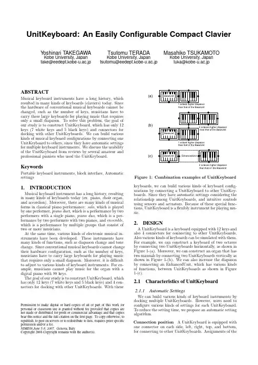
UnitKeyboard:An Easily Configurable Compact ClavierY oshinari TAKEGAWA Kobe University,Japan take@eedept.kobe-u.ac.jpTsutomu TERADAKobe University,Japantsutomu@eedept.kobe-u.ac.jpMasahiko TSUKAMOTOKobe University,Japantuka@kobe-u.ac.jpABSTRACTMusical keyboard instruments have a long history,which resulted in many kinds of keyboards(claviers)today.Since the hardware of conventional musical keyboards cannot be changed,such as the number of keys,musicians have to carry these large keyboards for playing music that requires only a small diapason.To solve this problem,the goal of our study is to construct UnitKeyboard,which has only12 keys(7white keys and5black keys)and connectors for docking with other UnitKeyboards.We can build various kinds of musical keyboard configurations by connecting one UnitKeyboard to others,since they have automatic settings for multiple keyboard instruments.We discuss the usability of the UnitKeyboard from reviews by several amateur and professional pianists who used the UnitKeyboard. KeywordsPortable keyboard instruments,block interface,Automatic settings1.INTRODUCTIONMusical keyboard instrument has a long history,resulting in many kinds of keyboards today(ex.piano,choir organ, and accordion).Moreover,there are many kinds of musical forms in classical piano performance:solo,which is played by one performer,piano duet,which is a performance by two performers with a single piano,piano duo,which is a per-formance by two performers with two pianos,and ensemble, which is a performance by multiple groups that consist of two or more musicians.At the same time,various kinds of electronic musical in-struments have been developed.These instruments have many kinds of functions,such as diapason change and tone change.Since conventional musical keyboards cannot change their hardware configuration,such as the number of keys, musicians have to carry large keyboards for playing music that requires only a small diapason.Moreover,it is difficult to adjust to various kinds of keyboard instruments.For ex-ample,musicians cannot play music for the organ with a digital piano with88keys.The goal of our study is to construct UnitKeyboard,which has only12keys(7white keys and5black keys)and4con-nectors for docking with other UnitKeyboards.With these Permission to make digital or hard copies of all or part of this work for personal or classroom use is granted without fee provided that copies are not made or distributed for profit or commercial advantage and that copies bear this notice and the full citation on thefirst page.To copy otherwise,to republish,to post on servers or to redistribute to lists,requires prior specific permission and/or a fee.NIME08,June5-8,2007,Genova,ItalyCopyright2008Copyright remains with the author(s).(a)(b)(c)than that of the BaseUnitthan that of the BaseUnit2 octaves higher diapasonthan that of the BaseUnit Figure1:Combination examples of UnitKeyboard keyboards,we can build various kinds of keyboard config-urations by connecting a UnitKeyboard to other UnitKey-boards.Since they have automatic settings considering the relationship among UnitKeyboards,and intuitive controls using sensors and actuators.Because of these special func-tions,UnitKeyboard is aflexibly instrument for playing mu-sic.2.DESIGNA UnitKeyboard is a keyboard equipped with12keys and also4connectors for connecting to other UnitKeyboards. Also various kinds of keyboards can be simulated with them. For example,we can construct a keyboard of two octaves by connecting two UnitKeyboards horizontally,as shown in Figure1-(a).Moreover,we can construct an organ that has two manuals by connecting two UnitKeyboards vertically as shown in Figure1-(b).We can also increase the diapason by connecting an EnhancedUnit,which has various kinds of functions,between UnitKeyboards as shown in Figure 1-(c).2.1Characteristics of UnitKeyboard2.1.1Automatic SettingsWe can build various kinds of keyboard instruments by docking multiple UnitKeyboards.However,users need to configure various kinds of settings for each UnitKeyboard. To reduce the setting time,we propose an automatic setting algorithm.Connection position A UnitKeyboard is equipped with one connector on each side,left,right,top,and bottom, for connecting to other UnitKeyboards.Assignments of theSound GeneratorFigure2:System structuretone and the diapason for each UnitKeyboard depend on the configuration of the connections.Generally,single man-ual keyboards like the piano,have characteristics that the more left/right the position of a key,the lower/higher its pitch,and all of the keys have the same tone.Therefore,a UnitKeyboard horizontally connected to a BaseUnit,which controls the base settings such as the tone and the diapa-son,inherits the tone of the BaseUnit,and a diapason of the UnitKeyboard increases one octave based on the diapason of the BaseUnit as shown in Figure1.On the other hand,a UnitKeyboard vertically connected to the BaseUnit has the same diapason as that of the BaseUnit,and the tone of the UnitKeyboard is independent from that of the BaseUnit. Priority Between a BaseUnit and a non-BaseUnit,there is a hierarchical relationship,that is,the settings of the non-BaseUnit inherit those of the BaseUnit.We define this as priority.This is similar to an ensemble,where the mul-tiple sections have section leaders or there is a conductor of the entire ensemble.Our system automatically assigns UnitKeyboard as low priority based on settings of a high priority UnitKeyboard.2.1.2Real-Time reconfigurationSince there may be cases where the configurations and connection statuses of the UnitKeyboards should be changed during the performance,the system needs to detect them and reconfigures the settings of the UnitKeyboards in real-time.We discuss the system design for fast real-time processing from the views points of data management.Data management In a UnitKeyboard system,there are various kinds of system data:connection data to manage the connection relationships among UnitKeyboards,setting data for setting the diapason and the tone of each UnitKey-board,and keying data that is generated when keys of a UnitKeyboard are pressed/released.Ifeach UnitKeyboard manages its own settings,each UnitKeyboard sends a connection change message to all the UnitKeyboards.Because the CPU and memory in a UnitKeyboard is limited,it is difficult to do this in real-time.Therefore,we use a computer as the“host”to calculate the connection statuses,setting statuses for all UnitKey-boards in the system.3.PROTOTYPE SYSTEMFigure2shows the structure of the prototype system. It consists of a host,UnitKeyboards,and EnhancedUnits.Figure3:A snapshot of UnitKeyboard Figure3shows a snapshot of a UnitKeyboard.We im-plemented the system using Microsoft Visual C++.NET 2003,and we use a Sony Vaio VGN-S92PS,with the Win-dows XP platform as the host,Allow7UM-100as a wireless module,Roland SC-8820as a MIDI sound generator,and M-audio OXYGEN8as the keyboard.OXYGEN8has25 keys but we cut one in half to make the12-keys.We use a programmable integrated circuit(PIC)microcomputer (PIC16F873)to control the UnitKeyboard and Enhance-dUnit.The software on the PIC is programmed in C lan-guage on Microchip Technology’s MPLAB.3.1HostIn the prototype,we used a PC as the host.The functions of the host are as follows.Management of setting data The host manages the setting data of each Unit.Note that a Unit includes teh UnitKeyboard and the EnhancedUnit.Management of connection statuses The host directly manages the connection statuses of all the Units.Moreover, the host calculates the setting data of each Unit’s configu-ration from the connection data of all the Units.Process of sound generation The host generates a MIDI Note On/Offmessages based on the setting data of the Units and keying data sent from a UnitKeyboard. 3.2UnitKeyboardThe hardware structure of a Unit is shown in Figure4.A UnitKeyboard consists of a PIC,a12-key keyboard connec-tors on all four sides,and a wireless module to communicate to the host.A UnitKeyboard has the following functions.Connector(EnhancedUnit Only )Figure 4:The hardware of UnitEstablishing connection to the host A UnitKeyboard broadcasts a “New Entry”command after it is turned on,and when the UnitKeyboard receives acknowledgement from the host,it sends an “ID”and “connector data”,such as the number of connectors,to the host.Sending keying data A UnitKeyboard sends keying data to the host,when the status of the UnitKeyboard keys is changed.Sending connection data A UnitKeyboard sends a “Con-nection Status”command to the host,when the status of its connectors is changed.3.3EnhancedUnitThe EnhancedUnit has two models:a simple model that only controls the diapason of a UnitKeyboard and a high-end model that is equipped with sensors,actuators,and a wireless module to operate settings of the UnitKeyboards.The former is inserted between UnitKeyboards to increase the diapason.It has a simple structure that consists of two connectors and a variable electric resistance.Since the con-nectors of a UnitKeyboard can measure the change of volt-age that works with the number of the variable resistance,UnitKeyboards that interleave with simple EnhancedUnits convert the amount of voltage to changing the diapason.Figure 4shows hardware of the high-end EnhancedUnit.The main differences between the EnhancedUnit and the UnitKeyboard are that the EnhancedUnit does not have a keyboard and has various input/output devices.The high-end EnhancedUnit has the following functions.Connection to the host The enhancedUnit broadcasts a “New Entry”command after the power is turned-on and establishes connections with the host just like a UnitKey-board.Sending connection data The EnhancedUnit monitors the status of its own connectors,and it sends a “Connection Status”command to the host when it detects a change of connection just like the UnitKeyboard.Sending of input data from input devices The En-hancedUnit collects data from input devices,and informs the host of this according to the requirements of the host.Control of output devices The EnhancedUnit controls output devices according to commands sent from the host.3.3.1Input/OutputdevicesWe developed a high-end EnhancedUnit prototype equipped with various kinds of input/output devices.Distance sensor Users can control diapasons of a UnitKey-A number of octave: [*]Figure 5:An EnhancedUnit with electric motor board neighboring an EnhancedUnit equipped with distance sensors.For example,the longer the distance between the UnitKeyboard and the EnhancedUnit,the higher the dia-pason of the UnitKeyboarda.Acceleration sensor Users control the tone of UnitKey-boards with the users’posture that is calculated and de-tected from data of the acceleration sensor.Motor Users can move UnitKeyboards automatically by using an EnhancedUnit equipped with motors attached to a propeller and wheels.For example,if musicians use an EnhancedUnit equipped with a motor and wheels,they can add/subtract a diapason by automatically moving a UnitKeyboard as shown in Figure 5.4.CONSIDERATIONSWe discuss the usability of proposed UnitKeyboard from the reviews by 5amateur pianists and 5professional pianists that actually used the UnitKeyboard.We have demon-strated UnitKeyboard in various kinds of events such as Kobe Luminarie Live Stage on December 8th and 9th,2007.It began in 1995and commemorates the Great Hanshin earthquake of that year about 4million participants at-tended last year.4.1Performance EvaluationVisibility We checked the function that automatically assigns the settings of the UnitKeyboard assuming the re-lationship among all the UnitKeyboards were working well.The host settled conflicting settings among the UnitKey-boards.Moreover,the proposed automatic-assignment al-gorithm was intuitive from participants’reviews.Because he participants could see the connection rela-tionships between the UnitKeyboards,it was easy to rec-ognize the relative diapason of each UnitKeyboard.How-ever,it was difficult to recognize the absolute diapason of each UnitKeyboard.In present implementation,partici-pants could not see the BaseUnit and the diapason of the BaseUnit.Therefore,participants had to press the keys of each UnitKeyboard to check the diapason.For future work,we plan to develop an EnhancedUnit with LEDs and a display for checking the settings of the UnitKeyboard.Wireless vs.Wired connections We adopted a wireless connection for communication between the host and the Units.In the wireless connection,although there was some de-lay between the keying to the output sound.The delay was not so noticeable in the music.However,the more UnitKey-boards were used,the higher the possibility was for packet loss and longer delays.On the other hand,the delay produced using wired con-nection was less than that of the wireless connection.Because both methods have advantages and disadvan-Figure6:Snapshots of collaborative performancetages,we will conduct a more detailed evaluation for eachmethod in future work.One-octave UnitKeyboard In this study,a UnitKey-board had only one octave from C to B.This diapason iseffective in music of only C major or C minor.We can solvethis problem by using the Mobile Clavier[7],which enablesa smooth change in diapason.4.2New performanceWe conducted performance with UnitKeyboards and En-hancedUnits.As shown in Figure6,when there was a lack of diapasonduring the performance,a musician solved it by borrow-ing a UnitKeyboard from another performer.Moreover,asshown in Figure5,a keyboard moving automatically to acommanded location was visually interesting.These perfor-mances are not only musically entertaining but also visuallyattractive.4.3RELATED WORKThere has been a large amount of research whose maingoal was improving a function by combining simple func-tional units.For example,users can control an object in agame by combining LEGO blocks[1],control website brows-ing by combining triangle boards[2],or control program-ming with combined blocks[3].Moreover,there are blockinterface equipped input/output devices[4].These targetswere not musical like our study.On the other hand,a system whose for music compositionfunctions by combining blocks assigned for mood music[5].Moreover,there are systems,DoublePad/Bass[6]and Mo-bile Clavier[7],which were developed to improve the porta-bility of acoustic instruments.DoublePad/Bass is base in-struments using two PDAs.Musicians who play an electricbass should be able to easily play it.Mobile Clavier en-ables the smooth change of diapason by allowing additionalblack keys to be inserted.These instruments were not de-signed with concept of combining units or for various kindsof keyboard/string instruments5.CONCLUSIONSWe proposed the UnitKeyboard,which can apply vari-ous kinds of keyboard instruments by connecting one-octavekeyboards together.Moreover,the UnitKeyboard has var-ious functions such as the automatic settings consideringthe relationship among multiple UnitKeyboards,intuitivecontrols and new performance using an EnhancedUnit.We intend to evaluate the hardware and the usability ofthe system in the future.6.ACKNOWLEDGMENTSThis research was supported in part by a Grant-in-Aid forScientific Research(A)(17200006)from the Japanese Min-istry of Education,Culture,Sports,Science and Technol-ogy,a Grant-in-Aid for Scientific Research from the JSPSResearch Fellowship,and by the Hayao Nakayama Founda-tion for Science&Technology and Culture.7.REFERENCES[1]Anderson,D.,Frankel,J.,Marks,J.,Agarwala,A.,Beardsley,P.,Hodgins,J.,Leigh,D.,Ryall,K.,Sullivan,E.and Yedida,J.:“Tangible InteractionGraphical Interpretation:A New Approach to3DModeling”,In Proceedings of SIGGRAPH2000,pp.393–402,2000.[2]Gorbet,G.M.,Orth,M.and Ishii,H.:“Triangles:Tangible Interface for Manipulation and Explorationof Digital Information Topography”,In Proceedingsof CHI1998,pp.49–56,1998.[3]Suzuki,H.and Kato,H.:“Interaction-level supportfor collaborative learning:AlgoBlock an openprogramming language”,In Proceedings ofCSCL2002,pp.349–355,2002.[4]Watanabe,R.,Itoh,Y.,Asai,M.,Kitamura,Y,Kishino,F.and Kikuchi,H.:“The Soul ofActiveCube-Implementing a Flexible,Multimodal,Three-Dimensional Spatial Tangible Interface”,InProceedings of ACE2004,pp.173–180,2004.[5]Henry,D.N.,Nakano,H.and Gibson,J.:“BlockJam”,In Proceedings of SIGGRAPH2002,pp.67,2002.[6]Terada,T.,Tsukamoto,M.and Nishio,S.:“APortable Electric Bass Using Two PDAs”,InProceedings of IWEC2002,pp.286–293,2002.[7]Takegawa,Y.,Terada,T.,Tsukamoto,M.and Nishio,S.:“Mobile Clavier:New Music Keyboard forFlexible Key Transpose”,In Proceedings of NIME2007,pp.82–87,2007.。
外文翻译--创业板市场
外文文献翻译译文一、外文原文原文:China's Second BoardI. Significance of and events leading to the establishment of a Second BoardOn 31 March 2009 the China Securities Regulatory Commission (CSRC issued Interim Measures on the Administration of Initial Public Offerings and Listings of Shares on the ChiNext [i.e., the Second Board, also called the Growth Enterprise Market] ("Interim Measures"), which came into force on 1 May 2009. This marked the creation by the Shenzhen Stock Exchange of the long-awaited market for venture businesses. As the original plan to establish such a market in 2001 had come to nothing when the dotcom bubble burst, the market's final opening came after a delay of nearly 10 years.Ever since the 1980s, when the Chinese government began to foster the development of science and technology, venture capital has been seen in China as a means of supporting the development of high-tech companies financially. The aim, as can be seen from the name of the 1996 Law of the People's Republic of China on Promoting the Conversion of Scientific and Technological Findings into Productivity ,was to support the commercialization of scientific and technological developments. Venture capital funds developed gradually in the late 1990s, and between then and 2000 it looked increasingly likely that a Second Board would be established. When the CSRC published a draft plan for this in September 2000, the stage was set. However, when the dotcom bubble (and especially the NASDAQ bubble) burst, this plan was shelved. Also, Chinese investors and venture capitalists were probably not quite ready for such a move.As a result, Chinese venture businesses sought to list on overseas markets (a so-called "red chip listing") from the late 1990s. However, as these listings increased, so did the criticism that valuable Chinese assets were being siphoned overseas.On thepolicy front, in 2004 the State Council published Some Opinions on Reform, Opening and Steady Growth of Capital Markets ("the Nine Opinions"), in which the concept of a "multi-tier capital market" was presented for the first time. A first step in this direction was made in the same year, when an SME Board was established as part of the Main Board. Although there appear to have been plans to eventually relax the SME Board's listing requirements, which were the same as those for companies listed on the Main Board, and to make it a market especially for venture businesses, it was decided to establish a separate market (the Second Board) for this purpose and to learn from the experience of the SME Board.As well as being part of the process of creating a multi-tier capital market, the establishment of the Second Board was one of the measures included in the policy document Several Opinions of the General Office of the State Council on Providing Financing Support for Economic Development ("the 30 Financial Measures"), published in December 2008 in response to the global financial crisis and intended as a way of making it easier for SMEs to raise capital.It goes without saying that the creation of the Second Board was also an important development in that it gives private equity funds the opportunity to exit their investments. The absence of such an exit had been a disincentive to such investment, with most funds looking for a red chip listing as a way of exiting their investments. However, with surplus savings at home, the Chinese authorities began to encourage companies to raise capital on the domestic market rather than overseas. This led, in September 2006, to a rule making it more difficult for Chinese venture businesses to list their shares on overseas markets. The corollary of this was that it increased the need for a means whereby Chinese private equity funds could exit their investments at an early opportunity and on their own market. The creation of the Second Board was therefore a belated response to this need.II. Rules and regulations governing the establishment of the Second BoardWe now take a closer look at some of the rules and regulations governing the establishment of the Second Board.First , the Interim Measures on the Administration of Initial Public Offerings andListings of Shares on the ChiNext, issued by the CSRC on 31 March 2009 with effect from 1 May 2009. The Interim Measures consist of six chapters and 58 articles, stipulating issue terms and procedures, disclosure requirements, regulatory procedures, and legal responsibilities.First, the General Provisions chapter. The first thing this says (Article 1) is: "These Measures are formulated for the purposes of promoting the development of innovative enterprises and other growing start-ups" This shows that one of the main listing criteria is a company's technological innovativeness and growth potential. The Chinese authorities have actually made it clear that, although the Second Board and the SME Board are both intended for SMEs of similar sizes, the Second Board is specifically intended for SMEs at the initial (rather than the growth or mature) stage of their development with a high degree of technological innovativeness and an innovative business model while the SME Board is specifically intended for companies with relatively stable earnings at the mature stage of their development. They have also made it clear that the Second Board is not simply a "small SME Board." This suggests to us that the authorities want to see technologically innovative companies listing on the Second Board and SMEs in traditional sectors listing on the SME Board.Next, Article 7 says: "A market access system that is commensurate with the risk tolerance of investors shall be established for investors on the ChiNext and investment risk shall be fully disclosed to investors." One noteworthy feature is the adoption of the concept of the "qualified investor" in an attempt to improve risk control.Furthermore, Article 8 says: "China Securities Regulatory Commission (hereinafter, CSRC) shall, in accordance with law, examine and approve the issuer’s IPO application and supervise the issuer’s IPO activities. The stock exchange shall formulate rules in accordance with law, provide an open, fair and equitable market environment and ensure the normal operation of the ChiNext." Until the Second Board was established, it was thought by some that the stock exchange had the right to approve new issues. Under the Interim Measures, however, it is the CSRC that examines and approves applications.First, offering conditions. Article 10 stipulates four numerical conditions for companies applying for IPOs.Second, offering procedures. The Interim Measures seek to make sponsoring securities companies more responsible by requiring them to conduct due diligence investigations and make prudential judgment on the issuer’s growth and render special opinions thereon.Third, information disclosure. Article 39 of the Interim Measures stipulates that the issuer shall make a statement in its prospectus pointing out the risks of investing in Second Board companies: namely, inconsistent performance, high operational risk, and the risk of delisting. Similarly,Fourth, supervision. Articles 51 and 52 stipulate that the stock exchange (namely, the Shenzhen Stock Exchange) shall establish systems for listing, trading and delisting Second Board stocks, urge sponsors to fulfill their ongoing supervisory obligations, and establish a market risk warning system and an investor education system.1. Amendments to the Interim Measures on Securities Issuance and Listing Sponsor System and the Provisional Measures of the Public Offering Review Committee of the China Securities Regulatory Commission2. Rules Governing the Listing of Shares on the ChiNext of Shenzhen Stock Exchange Next, the Shenzhen Stock Exchange published Rules Governing the Listing of Shares on the ChiNext of Shenzhen Stock Exchange on 6 June (with effect from 1 July).3. Checking investor eligibility As the companies listed on the Second Board are more risky than those listed on the Main Board and are subject to more rigorous delisting rules (see above), investor protection requires that checks be made on whether Second Board shares are suitable for all those wishing to invest in them.4. Rules governing (1) application documents for listings on the ChiNext and (2) prospectuses of ChiNext companies On 20 July the CSRC published rules governing Application Documents for Initial Public Offerings and Listings of Shares on the ChiNext and Prospectuses of ChiNext Companies, and announced that it would begin processing listing applications on 26 July.III. Future developmentsAs Its purpose is to "promote the development of innovative enterprises and other growing start-ups",the Second Board enables such companies to raise capital by issuing shares. That is why its listing requirements are less demanding than those of the Main Board but also why it has various provisions to mitigate risk. For one thing, the Second Board has its own public offering review committee to check how technologically specialized applicant companies are, reflecting the importance attached to this. For another, issuers and their controlling shareholders, de facto controllers, and sponsoring securities companies are subject to more demanding accountability requirements. The key factor here is, not surprisingly, disclosure. Also, the qualified investor system is designed to mitigate the risks to retail investors.Once the rules and regulations governing the Second Board were published, the CSRC began to process listing applications from 26 July 2009. It has been reported that 108 companies initially applied. As of mid-October, 28 of these had been approved and on 30 October they were listed on the Second Board.As of 15 December, there are 46 companies whose listing application has been approved by CSRC (including the above-mentioned 28 companies). They come from a wide range of sectors, especially information technology, services, and biopharmacy. Thus far, few companies in which foreign private equity funds have a stake have applied. This is because these funds have tended to go for red-chip listings.Another point is movement between the various tiers of China's multi-tier capital market. As of early September, four companies that are traded on the new Third Board had successfully applied to list on the Second Board. As 22 new Third Board companies meet the listing requirements of the Second Board on the basis of their interim reports for the first half of fiscal 2009, a growing number of companies may transfer their listing from the new Third Board to the Second Board. We think this is likely to make the new Third Board a more attractive market for private equity investors.The applicants include companies that were in the process of applying for a listing on the SME Board. The CSRC has also made it clear that it does not see theSecond Board simply as a "small SME Board" and attaches great importance to the companies' innovativeness and growth potential. Ultimately, whether or not such risks can be mitigated will depend on whether the quality of the companies that list on the Second Board improves and disclosure requirements are strictly complied with. For example, according to the rules governing Prospectuses of ChiNext Companies, companies are required to disclose the above-mentioned supplementary agreements as a control right risk. The point is whether such requirements will be complied with.Since there is a potentially large number of high-tech companies in China in the long term, whether or not the Second Board becomes one of the world's few successful venture capital markets will depend on whether all these rules and regulations succeed in shaping its development and the way in which it is run.The authorities clearly want to avoid a situation where the Second Board attracts a large number of second-rate companies and becomes a vehicle for market abuse as it would then run the risk of becoming an illiquid market shunned by investors who have lost trust in it. Indeed, such has been the number of companies applying to list on the Second Board that some observers have expressed concern about their quality.There has also been some concern about investor protection. For example, supplementary agreements between private equity funds and issuers pose a risk to retail investors in that they may suddenly be faced with a change in the controlling shareholder. This is because such agreements can result in a transfer of shares from the founder or controlling shareholder to a private equity fund if the company fails to meet certain agreed targets or in a shareholding structure that is different from the apparent one, for example. The problem of low liquidity, which has long faced the new Third Board market, where small-cap high-tech stocks are also traded, also needs to be addressed.Meanwhile, the Second Board's Public Offering Review Committee was officially established on 14 August. It has 35 members. A breakdown reveals that the number of representatives of the CSRC and the Shenzhen Stock Exchange has been limited to three and two, respectively, to ensure that the committee has the necessary number of technology specialists. Of the remainder, 14 are accountants, six lawyers,three from the Ministry of Science and Technology, three from the China Academy of Sciences, two from investment trust companies, one from an asset evaluation agency, and one from the National Development and Reform Commission (NDRC). It has been reported that the members include specialists in the six industry fields the CSRC considers particularly important for Second Board companies (namely, new energy, new materials, biotechnology and pharmaceuticals, energy conservation and environmental protection, services and IT).Source: Takeshi Jingu.2009.“China's Second Board”. Nomura Journal of Capital Markets Winter 2009 V ol.1 No.4.pp.1-15.二、翻译文章译文:中国创业板市场一、建立创业板市场及其意义2009年3月31日中国证券监督管理委员会(以下简称“中国证监会”)发行《中国证监会管理暂行办法》,首次在创业板市场上[即,第二个板,也叫创业板市场](“暂行办法”) 公开募股,从 2009年的5月1日开始生效,这标志着深圳证券交易所市场这个人们期待已久的合资企业即将诞生。
外文翻译原文
DOI10.1007/s10711-012-9699-zORIGINAL PAPERParking garages with optimal dynamicsMeital Cohen·Barak WeissReceived:19January2011/Accepted:22January2012©Springer Science+Business Media B.V.2012Abstract We construct generalized polygons(‘parking garages’)in which the billiard flow satisfies the Veech dichotomy,although the associated translation surface obtained from the Zemlyakov–Katok unfolding is not a lattice surface.We also explain the difficulties in constructing a genuine polygon with these properties.Keywords Active vitamin D·Parathyroid hormone-related peptide·Translation surfaces·Parking garages·Veech dichotomy·BilliardsMathematics Subject Classification(2000)37E351Introduction and statement of resultsA parking garage is an immersion h:N→R2,where N is a two dimensional compact connected manifold with boundary,and h(∂N)is afinite union of linear segments.A parking garage is called rational if the group generated by the linear parts of the reflections in the boundary segments isfinite.If h is actually an embedding,the parking garage is a polygon; thus polygons form a subset of parking garages,and rationals polygons(i.e.polygons all of whose angles are rational multiples ofπ)form a subset of rational parking garages.The dynamics of the billiardflow in a rational polygon has been intensively studied for over a century;see[7]for an early example,and[5,10,13,16]for recent surveys.The defi-nition of the billiardflow on a polygon readily extends to a parking garage:on the interior of N the billiardflow is the geodesicflow on the unit tangent bundle of N(with respect to the pullback of the Euclidean metric)and at the boundary,theflow is defined by elastic reflection (angle of incidence equals the angle of return).Theflow is undefined at thefinitely many M.Cohen·B.Weiss(B)Ben Gurion University,84105Be’er Sheva,Israele-mail:barakw@math.bgu.ac.ilM.Cohene-mail:comei@bgu.ac.ilpoints of N which map to‘corners’,i.e.endpoints of boundary segments,and hence at thecountable union of codimension1submanifolds corresponding to points in the unit tangentbundle for which the corresponding geodesics eventually arrive at corners in positive or neg-ative time.Since the direction of motion of a trajectory changes at a boundary segment viaa reflection in its side,for rational parking garages,onlyfinitely many directions of motionare assumed.In other words,the phase space of the billiardflow decomposes into invarianttwo-dimensional subsets corresponding tofixing the directions of motion.Veech[12]discovered that the billiardflow in some special polygons exhibits a strikingly he found polygons for which,in any initial direction,theflow is eithercompletely periodic(all orbits are periodic),or uniquely ergodic(all orbits are equidistrib-uted).Following McMullen we will say that a polygon with these properties has optimaldynamics.We briefly summarize Veech’s strategy of proof.A standard unfolding construc-tion usually attributed to Zemlyakov and Katok[15]1,associates to any rational polygon Pa translation surface M P,such that the billiardflow on P is essentially equivalent to thestraightlineflow on M P.Associated with any translation surface M is a Fuchsian group M,now known as the Veech group of M,which is typically trivial.Veech found M and P forwhich this group is a non-arithmetic lattice in SL2(R).We will call these lattice surfaces and lattice polygons respectively.Veech investigated the SL2(R)-action on the moduli space of translation surfaces,and building on earlier work of Masur,showed that lattice surfaces haveoptimal dynamics.From this it follows that lattice polygons have optimal dynamics.This chain of reasoning remains valid if one starts with a parking garage instead of apolygon;namely,the unfolding construction associates a translation surface to a parkinggarage,and one may define a lattice parking garage in an analogous way.The arguments ofVeech then show that the billiardflow in a lattice parking garage has optimal dynamics.Thisgeneralization is not vacuous:lattice parking garages,which are not polygons,were recentlydiscovered by Bouw and Möller[2].The term‘parking garage’was coined by Möller.A natural question is whether Veech’s result admits a converse,i.e.whether non-latticepolygons or parking garages may also have optimal dynamics.In[11],Smillie and the sec-ond-named author showed that there are non-lattice translation surfaces which have optimaldynamics.However translation surfaces arising from billiards form a set of measure zero inthe moduli space of translation surfaces,and it was not clear whether the examples of[11]arise from polygons or parking garages.In this paper we show:Theorem1.1There are non-lattice parking garages with optimal dynamics.An example of such a parking garage is shown in Fig.1.Veech’s work shows that for lattice polygons,the directions in which all orbits are periodicare precisely those containing a saddle connection,i.e.a billiard path connecting corners ofthe polygon which unfold to singularities of the corresponding surface.Following Cheunget al.[3],if a polygon P has optimal dynamics,and the periodic directions coincide with thedirections of saddle connections,we will say that P satisfies strict ergodicity and topologicaldichotomy.It is not clear to us whether our example satisfies this stronger property.As weexplain in Remark3.2below,this would follow if it were known that the center of the regularn-gon is a‘connection point’in the sense of Gutkin,Hubert and Schmidt[8]for some nwhich is an odd multiple of3.Veech also showed that for a lattice polygon P,the number N P(T)of periodic strips on P of length at most T satisfies a quadratic growth estimate of the form N P(T)∼cT2for a positive constant c.As we explain in Remark3.3,our examples also satisfy such a quadratic growth estimate.1But dating back at least to Fox and Kershner[7].Fig.1A non-lattice parkinggarage with optimal dynamics.(Here 2/n represents angle 2π/n )It remains an open question whether there is a genuine polygon which has optimal dynam-ics and is not a lattice polygon.Although our results make it seem likely that such a polygon exists,in her M.Sc.thesis [4],the first-named author obtained severe restrictions on such a polygon.In particular she showed that there are no such polygons which may be constructed from any of the currently known lattice examples via the covering construction as in [11,13].We explain these results and prove a representative special case in §4.2PreliminariesIn this section we cite some results which we will need,and deduce simple consequences.For the sake of brevity we will refer the reader to [10,11,16]for definitions of translation surfaces.Suppose S 1,S 2are compact orientable surfaces and π:S 2→S 1is a branched cover.That is,πis continuous and surjective,and there is a finite 1⊂S 1,called the set of branch points ,such that for 2=π−1( 1),the restriction of πto S 2 2is a covering map of finite degree d ,and for any p ∈ 1,#π−1(p )<d .A ramification point is a point q ∈ 2for which there is a neighborhood U such that {q }=U ∩π−1(π(q ))and for all u ∈U {q },# U ∩π−1(π(u )) ≥2.If M 1,M 2are translation surfaces,a translation map is a surjective map M 2→M 1which is a translation in charts.It is a branched cover.In contrast to other authors (cf.[8,13]),we do not require that the set of branch points be distinct from the singularities of M 1,or that they be marked.It is clear that the ramification points of the cover are singularities on M 2.If M is a lattice surface,a point p ∈M is called periodic if its orbit under the group of affine automorphisms of M is finite.A point p ∈M is called a connection point if any seg-ment joining a singularity with p is contained in a saddle connection (i.e.a segment joining singularities)on M .The following proposition summarizes results discussed in [7,9–11]:Proposition 2.1(a)A non-minimal direction on a translation surface contains a saddle connection.(b)If M 1is a lattice surface,M 2→M 1is translation map with a unique branch point,then any minimal direction on M 2is uniquely ergodic.(c)If M2→M1is a translation map such that M1is a lattice surface,then all branchpoints are periodic if and only if M2is a lattice surface.(d)If M2→M1is a translation map with a unique branch point,such that M1is a latticesurface and the branch point is a connection point,then any saddle connection direction on M2is periodic.Corollary2.2Let M2→M1be a translation map such that M1is a lattice surface with a unique branch point p.Then:(1)M2has optimal dynamics.(2)If p is a connection point then M2satisfies topological dichotomy and strict ergodicity.(3)If p is not a periodic point then M2is not a lattice surface.Proof To prove(1),by(b),the minimal directions are uniquely ergodic,and we need to prove that the remaining directions are either completely periodic or uniquely ergodic. By(a),in any non-minimal direction on M2there is a saddle connectionδ,and there are three possibilities:(i)δprojects to a saddle connection on M1.(ii)δprojects to a geodesic segment connecting the branch point p to itself.(iii)δprojects to a geodesic segment connecting p to a singularity.In case(i)and(ii)since M1is a lattice surface,the direction is periodic on M1,hence on M2as well.In case(iii),there are two subcases:ifδprojects to a part of a saddle connec-tion on M1,then it is also a periodic direction.Otherwise,in light of Proposition2.1(a),the direction must be minimal in M1,and hence,by Proposition2.1(b),uniquely ergodic in M2. This proves(1).Note also that if p is a connection point then the last subcase does not arise, so all directions which are non-minimal on M2are periodic.This proves(2).Statement(3) follows from(c).We now describe the unfolding construction[7,15],extended to parking garages.Let P=(h:N→R2).An edge of P is a connected subset L of∂N such that h(L)is a straight segment and L is maximal with these properties(with respect to inclusion).A vertex of P is any point which is an endpoint of an edge.The angle at a vertex is the total interior angle, measured via the pullback of the Euclidean metric,at the vertex.By convention we always choose the positive angles.Note that for polygons,angles are less than2π,but for parking garages there is no apriori upper bound on the angle at a vertex.Since our parking garages are rational,all angles are rational multiples ofπ,and we always write them as p/q,omitting πfrom the notation.Let G P be the dihedral group generated by the linear parts of reflections in h(L),for all edges L.For the sake of brevity,if there is a reflection with linear part gfixing a line parallel to L,we will say that gfixes L.Let S be the topological space obtained from N×G P by identifying(x,g1)with(x,g2)whenever g−11g2fixes an edge containing h(x).Topologically S is a compact orientable surface,and the immersions g◦h on each N×{g}induce an atlas of charts to R2which endows S with a translation surface structure.We denote this translation surface by M P,and writeπP for the map N×G P→M P.We will be interested in a‘partial unfolding’which is a variant of this construction,in which we reflect a parking garage repeatedly around several of its edges to form a larger parking garage.Formally,suppose P=(h:N→R2)and Q=(h :N →R2)are parking garages.For ≥1,we say that P tiles Q by reflections,and that is the number of tiles,if the following holds.There are maps h 1,...h :N→N and g1,...,g ∈G P(not necessarily distinct)satisfying:(A)The h i are homeomorphisms onto their images,and N = h i (N ).(B)For each i ,the linear part of h ◦h i ◦h −1is everywhere equal to g i .(C)For each 1≤i <j ≤ ,let L i j =h i (N )∩h j (N )and L =(h i )−1(L i j ).Then (h j )−1◦h i is the identity on L ,and L is either empty,or a vertex,or an edge of P .If L is an edge then h i (N )∪h j (N )is a neighborhood of L i j.If L i j is a vertex then there is a finite set of i =i 1,i 2,...,i k =j such that h i s (N )contains a neighborhood of L i j ,and each consecutive pair h i t (N ),h i t +1(N )intersect along an edge containing L i j .V orobets [13]realized that a tiling of parking garages gives rise to a branched cover.More precisely:Proposition 2.3Suppose P tiles Q by reflections with tiles,M P ,M Q are the correspond-ing translation surfaces obtained via the unfolding construction,and G P ,G Q are the cor-responding reflection groups.Then there is a translation map M Q →M P ,such that the following hold:(1)G Q ⊂G P .(2)The branch points are contained in the G P -orbit of the vertices of P .(3)The degree of the cover is [G P :G Q ].(4)Let z ∈M P be a point which is represented (as an element of N ×{1,...,r })by(x ,k )with x a vertex in P with angle m n (where gcd (m ,n )=1).Let (y i )⊂M Q be the pre-images of z,with angles k i m n in Q .Then z is a branch point of the cover if and only if k i n for some i.Proof Assertion (1)follows from the fact that Q is tiled by P .Since this will be impor-tant in the sequel,we will describe the covering map M Q →M P in detail.We will map (x ,g )∈N ×G Q to πP (x ,gg i )∈M P ,where x =h i (x ).We now check that this map is independent of the choice of x ,i ,and descends to a well-defined map M Q →M P ,which is a translation in charts.If x =h i (x 1)=h j (x 2)then x 1=x 2since (h i )−1◦h j is the identity.If x is in the relative interior of an edge L i j thenπP (x ,gg i )=πP (x ,gg j )(1)since (gg i )−1gg j =g −1i g j fixes an edge containing h (x 1).If x 1is a vertex of P then one proves (1)by an induction on k ,where k is as in (C).This shows that the map is well-defined.We now show that it descends to a map M Q →M P .Suppose (x ,g ),(x ,g )are two points in N ×G Q which are identified in M Q ,i.e.x ∈∂N is in the relative interior of an edge fixed by g −1g .By (C)there is a unique i such that x is in the image of h i .Thus (x ,g )maps to (x ,gg i )and (x ,g )maps to (x ,g g i ),and g −1i g −1g g i fixes the edge through x =g −1i (x ).It remains to show that the map we have defined is a translation in charts.This follows immediately from the chain rule and (B).Assertion (2)is simple and left to the reader.For assertion (3)we note that M P (resp.M Q )is made of |G P |(resp. |G Q |)copies of P .The point z will be a branch point if and only if the total angle around z ∈M P differs from the total angle around one of the pre-images y i ∈M Q .The total angle at a singularity corresponding to a vertex with angle r /s (where gcd (r ,s )=1)is 2r π,thus the total angle at z is 2m πand the total angle at y i is 2k i m πgcd (k i ,n ).Assertion (4)follows.3Non-lattice dynamically optimal parking garagesIn this section we prove the following result,which immediately implies Theorem1.1: Theorem3.1Let n≥9be an odd number divisible by3,and let P be an isosceles triangle with equal angles1/n.Let Q be the parking garage made of four copies of P glued as in Fig.1, so that Q has vertices(in cyclic order)with angles1/n,2/n,3/n,(n−2)/n,2/n,3(n−2)/n. Then M P is a lattice surface and M Q→M P is a translation map with one aperiodic branchpoint.In particular Q is a non-lattice parking garage with optimal dynamics.Proof The translation surface M P is the double n-gon,one of Veech’s original examples of lattice surfaces[12].The groups G P and G Q are both equal to the dihedral group D n.Thus by Proposition2.3,the degree of the cover M Q→M P is four.Again by Proposition2.3, since n is odd and divisible by3,the only vertices which correspond to branch points are the two vertices z1,z2with angle2/n(they correspond to the case k i=2while the other vertices correspond to1or3).In the surface M P there are two points which correspond to vertices of equal angle in P(the centers of the two n-gons),and these points are known to be aperiodic [9].We need to check that z1and z2both map to the same point in M P.This follows from the fact that both are opposite the vertex z3with angle3/n,which also corresponds to the center of an n-gon,so in M P project to a point which is distinct from z3. Remark3.2As of this writing,it is not known whether the center of the regular n-gon is a connection point on the double n-gon surface.If this turns out to be the case for some n which is an odd multiple of3,then by Corollary2.2(2),our construction satisfies strict ergodicity and topological dichotomy.See[1]for some recent related results.Remark3.3Since our examples are obtained by taking branched covers over lattice surfaces, a theorem of Eskin et al.[6,Thm.8.12]shows that our examples also satisfy a quadratic growth estimate of the form N P(T)∼cT2;moreover§9of[6]explains how one may explicitly compute the constant c.4Non-lattice optimal polygons are hard tofindIn this section we present results indicating that the above considerations will not easily yield a non-lattice polygon with optimal dynamics.Isolating the properties necessary for our proof of Theorem3.1,we say that a pair of polygons(P,Q)is suitable if the following hold:•P is a lattice polygon.•P tiles Q by reflections.•The corresponding cover M Q→M P as in Proposition2.3has a unique branch point which is aperiodic.In her M.Sc.thesis at Ben Gurion University,thefirst-named author conducted an exten-sive search for a suitable pair of polygons.By Corollary2.2,such a pair will have yielded a non-lattice polygon with optimal dynamics.The search begins with a list of candidates for P,i.e.a list of currently known lattice polygons.At present,due to work of many authors, there is a fairly large list of known lattice polygons but there is no classification of all lattice polygons.In[4],the full list of lattice polygons known as of this writing is given,and the following is proved:Theorem4.1(M.Cohen)Among the list of lattice surfaces given in[4],there is no P for which there is Q such that(P,Q)is a suitable pair.The proof of Theorem4.1contains a detailed case-by-case analysis for each of the differ-ent possible P.These cases involve some common arguments which we will illustrate in this section,by proving the special case in which P is any of the obtuse triangles investigated byWard[14]:Theorem4.2For n≥4,let P=P n be the(lattice)triangle with angles1n,12n,2n−32n.Then there is no polygon Q for which(P,Q)is a suitable pair.Our proof relies on some auxiliary statements which are of independent interest.In all of them,M Q→M P is the branched cover with unique branch point corresponding to a suitable pair(P,Q).These statements are also valid in the more general case in which P,Q are parking garages.Recall that an affine automorphism of a translation surface is a homeomorphism which is linear in charts.We denote by Aff(M)the group of affine automorphisms of M and by D:Aff(M)→GL2(R)the homomorphism mapping an affine automorphism to its linear part.Note that we allow orientation-reversing affine automorphisms,i.e.detϕmay be1 or−1.We now explain how G P acts on M P by translation equivalence.LetπP:N×G P→M P and S be as in the discussion preceding Proposition2.3,and let g∈G P.Since the left action of g on G is a permutation and preserves the gluing ruleπP,the map N×G P→N×G P sending(x,g )to(x,g−1g )induces a homeomorphismϕ:S→S and g◦h◦ϕis a translation in charts.Thus g∈G P gives a translation isomorphism of M P,and similarly g∈G P gives a translation isomorphism of M Q.Lemma4.3The branch point of the cover p:M Q→M P isfixed by G Q.Proof Since G Q⊂G P,any g∈G Q induces translation isomorphisms of both M P and M Q.We denote both by g.The definition of p given in thefirst paragraph of the proof of Proposition2.3shows that p◦g=g◦p;namely both maps are induced by sending (x ,g )∈N ×G Q toπP(x,gg g i),where x =h i(x).Since the cover p has a unique branch point,any g∈G Q mustfix it. Lemma4.4If an affine automorphismϕof a translation surface has infinitely manyfixed points then Dϕfixes a nonzero vector,in its linear action on R2.Proof Suppose by contradiction that the linear action of Dϕon the plane has zero as a uniquefixed point,and let Fϕbe the set offixed points forϕ.For any x∈Fϕwhich is not a singularity,there is a chart from a neighborhood U x of x to R2with x→0,and a smaller neighborhood V x⊂U x,such thatϕ(V x)⊂U x and when expressed in this chart,ϕ|V x is given by the linear action of Dϕon the plane.In particular x is the onlyfixed point in V x. Similarly,if x∈Fϕis a singularity,then there is a neighborhood U x of x which maps to R2 via afinite branched cover ramified at x→0,such that the action ofϕin V x⊂U x covers the linear action of Dϕ.Again we see that x is the onlyfixed point in V x.By compactness wefind that Fϕisfinite,contrary to hypothesis. Lemma4.5Suppose M is a lattice surface andϕ∈Aff(M)has Dϕ=−Id.Then afixed point forϕis periodic.Proof LetF1={σ∈Aff(M):Dσ=−Id}.Thenϕ∈F1and F1isfinite,since it is a coset for the group ker D which is known to be finite.Let A⊂M be the set of points which arefixed by someσ∈F1.By Lemma4.4this is afinite set,which contains thefixed points forϕ.Thus in order to prove the Lemma,it suffices to show that A is Aff(M)-invariant.Letψ∈Aff(M),and let x∈A,so that x=σ(x)with Dσ=−Id.Since-Id is central in GL2(R),D(σψ)=D(ψσ),so there is f∈ker D such thatψσ=fσψ.Thereforeψ(x)=ψσ(x)=fσψ(x),and fσ∈F1.This proves thatψ(x)∈A.Remark4.6This improves Theorem10of[8],where a similar conclusion is obtained under the additional assumptions that M is hyperelliptic and Aff(M)is generated by elliptic ele-ments.The following are immediate consequences:Corollary4.7Suppose(P,Q)is a suitable pair.Then•−Id/∈D(G Q).•None of the angles between two edges of Q are of the form p/q with gcd(p,q)=1and q even.Proof of Theorem4.2We will suppose that Q is such that(P,Q)are a suitable pair and reach a contradiction.If n is even,then Aff(M P)contains a rotation byπwhichfixes the points in M P coming from vertices of P.Thus by Lemma4.5all vertices of P give rise to periodic points,contradicting Proposition2.1(c).So n must be odd.Let x1,x2,x3be the vertices of P with corresponding angles1/n,1/2n,(2n−3)/2n. Then x3gives rise to a singularity,hence a periodic point.Also using Lemma4.5and the rotation byπ,one sees that x2also gives rise to a periodic point.So the unique branch point must correspond to the vertex x1.The images of the vertex x1in P give rise to two regular points in M P,marked c1,c2in Fig.2.Any element of G P acts on{c1,c2}by a permutation, so by Lemma4.3,G Q must be contained in the subgroup of index twofixing both of the c i. Let e1be the edge of P opposite x1.Since the reflection in e1,or any edge which is an image of e1under G P,swaps the c i,we have:e1is not a boundary edge of Q.(2) We now claim that in Q,any vertex which corresponds to the vertex x3from P is alwaysdoubled,i.e.consists of an angle of(2n−3)/n.Indeed,for any polygon P0,the group G P0 is the dihedral group D N where N is the least common multiple of the denominators of theangles at vertices of P0.In particular it contains-Id when N is even.Writing(2n−3)/2n in reduced form we have an even denominator,and since,by Corollary4.7,−Id/∈G Q,in Q the angle at vertex x3must be multiplied by an even integer2k.Since2k(2n−3)/2n is bigger than2if k>1,and since the total angle at a vertex of a polygon is less than2π,we must have k=1,i.e.any vertex in Q corresponding to the vertex x3is always doubled.This establishes the claim.It is here that we have used the assumption that Q is a polygon and not a parking garage.Fig.2Ward’s surface,n=5Fig.3Two options to start the construction ofQThere are two possible configurations in which a vertex x3is doubled,as shown in Fig.3. The bold lines indicate lines which are external,i.e.boundary edges of Q.By(2),the con-figuration on the right cannot occur.Let us denote the polygon on the left hand side of Fig.3by Q0.It cannot be equal to Q,since it is a lattice polygon.We now enlarge Q0by adding copies of P step by step,as described in Fig.4.Without loss of generality wefirst add triangle number1.By(2),the broken line indicates a side which must be internal in Q.Therefore,we add triangle number 2.We denote the resulting polygon by Q1.One can check by computing angles,using thefact that n is odd,and using Proposition2.3(4)that the cover M Q1→M P will branch overthe points a corresponding to vertex x2.Since the allowed branching is only over the points corresponding to x1,we must have Q1 Q,so we continue the construction.Without loss of generality we add triangle number3.Again,by(2),the broken line indicates a side which must be internal in Q.Therefore,we add triangle number4,obtaining Q2.Now,using Prop-osition2.3(4)again,in the cover M Q2→M P we have branching over two vertices u andv which are both of type x1and correspond to distinct points c1and c2in M P.This implies Q2 Q.Fig.4Steps of the construction of QSince both vertices u and v are delimited by2external sides,we cannot change the angle to prevent the branching over one of these points.This means that no matter how we continue to construct Q,the branching in the cover M Q→M P will occur over at least two points—a contradiction.Acknowledgments We are grateful to Yitwah Cheung and Patrick Hooper for helpful discussions,and to the referee for a careful reading and helpful remarks which improved the presentation.This research was supported by the Israel Science Foundation and the Binational Science Foundation.References1.Arnoux,P.,Schmidt,T.:Veech surfaces with non-periodic directions in the tracefield.J.Mod.Dyn.3(4),611–629(2009)2.Bouw,I.,Möller,M.:Teichmüller curves,triangle groups,and Lyapunov exponents.Ann.Math.172,139–185(2010)3.Cheung,Y.,Hubert,P.,Masur,H.:Topological dichotomy and strict ergodicity for translation surfaces.Ergod.Theory Dyn.Syst.28,1729–1748(2008)4.Cohen,M.:Looking for a Billiard Table which is not a Lattice Polygon but satisfies the Veech dichotomy,M.Sc.thesis,Ben-Gurion University(2010)/pdf/1011.32175.DeMarco,L.:The conformal geometry of billiards.Bull.AMS48(1),33–52(2011)6.Eskin,A.,Marklof,J.,Morris,D.:Unipotentflows on the space of branched covers of Veech surfaces.Ergod.Theorm Dyn.Syst.26(1),129–162(2006)7.Fox,R.H.,Kershner,R.B.:Concerning the transitive properties of geodesics on a rational polyhe-dron.Duke Math.J.2(1),147–150(1936)8.Gutkin,E.,Hubert,P.,Schmidt,T.:Affine diffeomorphisms of translation surfaces:Periodic points,Fuchsian groups,and arithmeticity.Ann.Sci.École Norm.Sup.(4)36,847–866(2003)9.Hubert,P.,Schmidt,T.:Infinitely generated Veech groups.Duke Math.J.123(1),49–69(2004)10.Masur,H.,Tabachnikov,S.:Rational billiards andflat structures.In:Handbook of dynamical systems,vol.1A,pp.1015–1089.North-Holland,Amsterdam(2002)11.Smillie,J.,Weiss,B.:Veech dichotomy and the lattice property.Ergod.Theorm.Dyn.Syst.28,1959–1972(2008)Geom Dedicata12.Veech,W.A.:Teichmüller curves in moduli space,Eisenstein series and an application to triangularbilliards.Invent.Math.97,553–583(1989)13.V orobets,Y.:Planar structures and billiards in rational polygons:the Veech alternative.(Russian);trans-lation in Russian Math.Surveys51(5),779–817(1996)14.Ward,C.C.:Calculation of Fuchsian groups associated to billiards in a rational triangle.Ergod.TheoryDyn.Syst.18,1019–1042(1998)15.Zemlyakov,A.,Katok,A.:Topological transitivity of billiards in polygons,Math.Notes USSR Acad.Sci:18:2291–300(1975).(English translation in Math.Notes18:2760–764)16.Zorich,A.:Flat surfaces.In:Cartier,P.,Julia,B.,Moussa,P.,Vanhove,P.(eds.)Frontiers in numbertheory,physics and geometry,Springer,Berlin(2006)123。
毕业论文外文翻译范例

外文原文(一)Savigny and his Anglo-American Disciple s*M. H. HoeflichFriedrich Carl von Savigny, nobleman, law reformer, champion of the revived German professoriate, and founder of the Historical School of jurisprudence, not only helped to revolutionize the study of law and legal institutions in Germany and in other civil law countries, but also exercised a profound influence on many of the most creative jurists and legal scholars in England and the United States. Nevertheless, tracing the influence of an individual is always a difficult task. It is especially difficult as regards Savigny and the approach to law and legal sources propounded by the Historical School. This difficulty arises, in part, because Savigny was not alone in adopting this approach. Hugo, for instance, espoused quite similar ideas in Germany; George Long echoed many of these concepts in England during the 1850s, and, of course, Sir Henry Sumner Maine also espoused many of these same concepts central to historical jurisprudence in England in the 1860s and 1870s. Thus, when one looks at the doctrinal writings of British and American jurists and legal scholars in the period before 1875, it is often impossible to say with any certainty that a particular idea which sounds very much the sort of thing that might, indeed, have been derived from Savigny's works, was, in fact, so derived. It is possible, nevertheless, to trace much of the influence of Savigny and his legal writings in the United States and in Great Britain during this period with some certainty because so great was his fame and so great was the respect accorded to his published work that explicit references to him and to his work abound in the doctrinal writing of this period, as well as in actual law cases in the courts. Thus, Max Gutzwiller, in his classic study Der einfluss Savignys auf die Entwicklung des International privatrechts, was able to show how Savigny's ideas on conflict of laws influenced such English and American scholars as Story, Phillimore, Burge, and Dicey. Similarly, Andreas Schwarz, in his "Einflusse Deutscher Zivilistik im Auslande," briefly sketched Savigny's influence upon John Austin, Frederick Pollock, and James Bryce. In this article I wish to examine Savigny's influence over a broader spectrum and to draw a picture of his general fame and reputation both in Britain and in the United States as the leading Romanist, legal historian, and German legal academic of his day. The picture of this Anglo-American respect accorded to Savigny and the historical school of jurisprudence which emerges from these sources is fascinating. It sheds light not only upon Savigny’s trans-channel, trans-Atlantic fame, but also upon the extraordinarily*M.H.Hoeflich, Savigny and his Anglo-American Disciples, American Journal of Comparative Law, vol.37, No.1, 1989.cosmopolitan outlook of many of the leading American and English jurists of the time. Of course, when one sets out to trace the influence of a particular individual and his work, it is necessary to demonstrate, if possible, precisely how knowledge of the man and his work was transmitted. In the case of Savigny and his work on Roman law and ideas of historical jurisprudence, there were three principal modes of transmission. First, there was the direct influence he exercised through his contacts with American lawyers and scholars. Second, there was the influence he exercised through his books. Third, there was the influence he exerted indirectly through intermediate scholars and their works. Let us examine each mode separately.I.INFLUENCE OF THE TRANSLATED WORKSWhile American and British interest in German legal scholarship was high in the antebellum period, the number of American and English jurists who could read German fluently was relatively low. Even those who borrowed from the Germans, for instance, Joseph Story, most often had to depend upon translations. It is thus quite important that Savigny’s works were amongst the most frequently translated into English, both in the United States and in Great Britain. His most influential early work, the Vom Beruf unserer Zeitfur Rechtsgeschichte und Gestzgebung, was translated into English by Abraham Hayward and published in London in 1831. Two years earlier the first volume of his History of Roman Law in the Middle Ages was translated by Cathcart and published in Edinburgh. In 1830, as well, a French translation was published at Paris. Sir Erskine Perry's translation of Savigny's Treatise on Possession was published in London in 1848. This was followed by Archibald Brown's epitome of the treatise on possession in 1872 and Rattigan's translation of the second volume of the System as Jural Relations or the Law of Persons in 1884. Guthrie published a translation of the seventh volume of the System as Private International Law at Edinburgh in 1869. Indeed, two English translations were even published in the far flung corners of the British Raj. A translation of the first volume of the System was published by William Holloway at Madras in 1867 and the volume on possession was translated by Kelleher and published at Calcutta in 1888. Thus, the determined English-speaking scholar had ample access to Savigny's works throughout the nineteenth century.Equally important for the dissemination of Savigny's ideas were those books and articles published in English that explained and analyzed his works. A number of these must have played an important role in this process. One of the earliest of these is John Reddie's Historical Notices of the Roman law and of the Progress of its Study in Germany, published at Edinburgh in 1826. Reddie was a noted Scots jurist and held the Gottingen J.U.D. The book, significantly, is dedicated to Gustav Hugo. It is of that genre known as an external history of Roman law-not so much a history of substantive Roman legal doctrine but rather a historyof Roman legal institutions and of the study of Roman law from antiquity through the nineteenth century. It is very much a polemic for the study of Roman law and for the Historical School. It imparts to the reader the excitement of Savigny and his followers about the study of law historically and it is clear that no reader of the work could possibly be left unmoved. It is, in short, the first work of public relations in English on behalf of Savigny and his ideas.Having mentioned Reddie's promotion of Savigny and the Historical School, it is important to understand the level of excitement with which things Roman and especially Roman law were greeted during this period. Many of the finest American jurists were attracted-to use Peter Stein's term-to Roman and Civil law, but attracted in a way that, at times, seems to have been more enthusiastic than intellectual. Similarly, Roman and Civil law excited much interest in Great Britain, as illustrated by the distinctly Roman influence to be found in the work of John Austin. The attraction of Roman and Civil law can be illustrated and best understood, perhaps, in the context of the publicity and excitement in the English-speaking world surrounding the discovery of the only complete manuscript of the classical Roman jurist Gaius' Institutes in Italy in 1816 by the ancient historian and German consul at Rome, B.G. Niebuhr. Niebuhr, the greatest ancient historian of his time, turned to Savigny for help with the Gaius manuscript (indeed, it was Savigny who recognized the manuscript for what it was) and, almost immediately, the books and journals-not just law journals by any means-were filled with accounts of the discovery, its importance to legal historical studies, and, of course, what it said. For instance, the second volume of the American Jurist contains a long article on the civil law by the scholarly Boston lawyer and classicist, John Pickering. The first quarter of the article is a gushing account of the discovery and first publication of the Gaius manuscript and a paean to Niebuhr and Savigny for their role in this. Similarly, in an article published in the London Law Magazine in 1829 on the civil law, the author contemptuously refers to a certain professor who continued to tell his students that the text of Gaius' Institutes was lost for all time. What could better show his ignorance of all things legal and literary than to be unaware of Niebuhr's great discovery?Another example of this reaction to the discovery of the Gaius palimpsest is to be found in David Irving's Introduction to the Study of the Civil Law. This volume is also more a history of Roman legal scholarship and sources than a study of substantive Roman law. Its pages are filled with references to Savigny's Geschichte and its approach clearly reflects the influence of the Historical School. Indeed, Irving speaks of Savigny's work as "one of the most remarkable productions of the age." He must have been truly impressed with German scholarship and must also have been able to convince the Faculty of Advocates, forwhom he was librarian, of the worth of German scholarship, for in 1820 the Faculty sent him to Gottingen so that he might study their law libraries. Irving devotes several pages of his elementary textbook on Roman law to the praise of the "remarkable" discovery of the Gaius palimpsest. He traces the discovery of the text by Niebuhr and Savigny in language that would have befitted an adventure tale. He elaborates on the various labors required to produce a new edition of the text and was particularly impressed by the use of a then new chemical process to make the under text of the palimpsest visible. He speaks of the reception of the new text as being greeted with "ardor and exultation" strong words for those who spend their lives amidst the "musty tomes" of the Roman law.This excitement over the Verona Gaius is really rather strange. Much of the substance of the Gaius text was already known to legal historians and civil lawyers from its incorporation into Justinian's Institutes and so, from a substantive legal perspective, the find was not crucial. The Gaius did provide new information on Roman procedural rules and it did also provide additional information for those scholars attempting to reconstruct pre-Justinianic Roman law. Nevertheless, these contributions alone seem hardly able to justify the excitement the discovery caused. Instead, I think that the Verona Gaius discovery simply hit a chord in the literary and legal community much the same as did the discovery of the Rosetta Stone or of Schliemann’s Troy. Here was a monument of a great civilization brought newly to light and able to be read for the first time in millenia. And just as the Rosetta Stone helped to establish the modern discipline of Egyptology and Schliemann's discoveries assured the development of classical archaeology as a modern academic discipline, the discovery of the Verona Gaius added to the attraction Roman law held for scholars and for lawyers, even amongst those who were not Romanists by profession. Ancillary to this, the discovery and publication of the Gaius manuscript also added to the fame of the two principals involved in the discovery, Niebuhr and Savigny. What this meant in the English-speaking world is that even those who could not or did not wish to read Savigny's technical works knew of him as one of the discoverers of the Gaius text. This fame itself may well have helped in spreading Savigny's legal and philosophical ideas, for, I would suggest, the Gaius "connection" may well have disposed people to read other of Savigny's writings, unconnected to the Gaius, because they were already familiar with his name.Another example of an English-speaking promoter of Savigny is Luther Stearns Cushing, a noted Boston lawyer who lectured on Roman law at the Harvard Law School in 1848-49 and again in 1851- 1852.Cushing published his lectures at Boston in 1854 under the title An Introduction to the Study of Roman Law. He devoted a full chapter to a description of the historical school and to the controversy betweenSavigny and Thibaut over codification. While Cushing attempted to portray fairly the arguments of both sides, he left no doubt as to his preference for Savigny's approach:The labors of the historical school have established an entirely new and distinct era in the study of the Roman jurisprudence; and though these writers cannot be said to have thrown their predecessors into the shade, it seems to be generally admitted, that almost every branch of the Roman law has received some important modification at their hands, and that a knowledge of their writings, to some extent, at least, is essentially necessary to its acquisition.译文(一)萨维尼和他的英美信徒们*M·H·豪弗里奇弗雷德里奇·卡尔·冯·萨维尼出身贵族,是一位出色的法律改革家,也是一位倡导重建德国教授协会的拥护者,还是历史法学派的创建人之一。
毕业论文文献外文翻译----危机管理:预防,诊断和干预文献翻译-中英文文献对照翻译

第1页 共19页中文3572字毕业论文(设计)外文翻译标题:危机管理-预防,诊断和干预一、外文原文标题:标题:Crisis management: prevention, diagnosis and Crisis management: prevention, diagnosis andintervention 原文:原文:The Thepremise of this paper is that crises can be managed much more effectively if the company prepares for them. Therefore, the paper shall review some recent crises, theway they were dealt with, and what can be learned from them. Later, we shall deal with the anatomy of a crisis by looking at some symptoms, and lastly discuss the stages of a crisis andrecommend methods for prevention and intervention. Crisis acknowledgmentAlthough many business leaders will acknowledge thatcrises are a given for virtually every business firm, many of these firms do not take productive steps to address crisis situations. As one survey of Chief Executive officers of Fortune 500 companies discovered, 85 percent said that a crisisin business is inevitable, but only 50 percent of these had taken any productive action in preparing a crisis plan(Augustine, 1995). Companies generally go to great lengths to plan their financial growth and success. But when it comes to crisis management, they often fail to think and prepare for those eventualities that may lead to a company’s total failure.Safety violations, plants in need of repairs, union contracts, management succession, and choosing a brand name, etc. can become crises for which many companies fail to be prepared untilit is too late.The tendency, in general, is to look at the company as a perpetual entity that requires plans for growth. Ignoring the probabilities of disaster is not going to eliminate or delay their occurrences. Strategic planning without inclusion ofcrisis management is like sustaining life without guaranteeinglife. One reason so many companies fail to take steps to proactively plan for crisis events, is that they fail to acknowledge the possibility of a disaster occurring. Like an ostrich with its head in the sand, they simply choose to ignorethe situation, with the hope that by not talking about it, it will not come to pass. Hal Walker, a management consultant, points out “that decisions will be more rational and better received, and the crisis will be of shorter duration, forcompanies who prepare a proactive crisis plan” (Maynard, 1993) .It is said that “there are two kinds of crises: those that thatyou manage, and those that manage you” (Augustine, 1995). Proactive planning helps managers to control and resolve a crisis. Ignoring the possibility of a crisis, on the other hand,could lead to the crisis taking a life of its own. In 1979, theThree-Mile Island nuclear power plant experienced a crisis whenwarning signals indicated nuclear reactors were at risk of a meltdown. The system was equipped with a hundred or more different alarms and they all went off. But for those who shouldhave taken the necessary steps to resolve the situation, therewere no planned instructions as to what should be done first. Hence, the crisis was not acknowledged in the beginning and itbecame a chronic event.In June 1997, Nike faced a crisis for which they had no existi existing frame of reference. A new design on the company’s ng frame of reference. A new design on the company’s Summer Hoop line of basketball shoes - with the word air writtenin flaming letters - had sparked a protest by Muslims, who complained the logo resembled the Arabic word for Allah, or God.The council of American-Islamic Relations threatened aa globalNike boycott. Nike apologized, recalled 38,000 pairs of shoes,and discontinued the line (Brindley, 1997). To create the brand,Nike had spent a considerable amount of time and money, but hadnever put together a general framework or policy to deal with such controversies. To their dismay, and financial loss, Nike officials had no choice but to react to the crisis. This incident has definitely signaled to the company that spending a little more time would have prevented the crisis. Nonetheless,it has taught the company a lesson in strategic crisis management planning.In a business organization, symptoms or signals can alert the strategic planners or executives of an eminent crisis. Slipping market share, losing strategic synergy anddiminishing productivity per man hour, as well as trends, issues and developments in the socio-economic, political and competitive environments, can signal crises, the effects of which can be very detrimental. After all, business failures and bankruptcies are not intended. They do not usually happen overnight. They occur more because of the lack of attention to symptoms than any other factor.Stages of a crisisMost crises do not occur suddenly. The signals can usuallybe picked up and the symptoms checked as they emerge. A company determined to address these issues realizes that the real challenge is not just to recognize crises, but to recognize themin a timely fashion (Darling et al., 1996). A crisis can consistof four different and distinct stages (Fink, 1986). The phasesare: prodromal crisis stage, acute crisis stage, chronic crisisstage and crisis resolution stage.Modern organizations are often called “organic” due tothe fact that they are not immune from the elements of their surrounding environments. Very much like a living organism, organizations can be affected by environmental factors both positively and negatively. But today’s successfulorganizations are characterized by the ability to adapt by recognizing important environmental factors, analyzing them, evaluating the impacts and reacting to them. The art of strategic planning (as it relates to crisis management)involves all of the above activities. The right strategy, in general, provides for preventive measures, and treatment or resolution efforts both proactively and reactively. It wouldbe quite appropriate to examine the first three stages of acrisis before taking up the treatment, resolution or intervention stage.Prodromal crisis stageIn the field of medicine, a prodrome is a symptom of the onset of a disease. It gives a warning signal. In business organizations, the warning lights are always blinking. No matter how successful the organization, a number of issues andtrends may concern the business if proper and timely attentionis paid to them. For example, in 1995, Baring Bank, a UK financial institution which had been in existence since 1763,ample opportunitysuddenly and unexpectedly failed. There wasfor the bank to catch the signals that something bad was on thehorizon, but the company’s efforts to detect that were thwarted by an internal structure that allowed a single employee both to conduct and to oversee his own investment trades, and the breakdown of management oversight and internalcontrol systems (Mitroff et al., 1996). Likewise, looking in retrospect, McDonald’s fast food chain was given the prodromalsymptoms before the elderly lady sued them for the spilling ofa very hot cup of coffee on her lap - an event that resulted in a substantial financial loss and tarnished image of thecompany. Numerous consumers had complained about thetemperature of the coffee. The warning light was on, but the company did not pay attention. It would have been much simplerto pick up the signal, or to check the symptom, than facing the consequences.In another case, Jack in the Box, a fast food chain, had several customers suffer intestinal distress after eating at their restaurants. The prodromal symptom was there, but the company took evasive action. Their initial approach was to lookaround for someone to blame. The lack of attention, the evasiveness and the carelessness angered all the constituent groups, including their customers. The unfortunate deaths thatptoms,occurred as a result of the company’s ignoring thesymand the financial losses that followed, caused the company to realize that it would have been easier to manage the crisis directly in the prodromal stage rather than trying to shift theblame.Acute crisis stageA prodromal stage may be oblique and hard to detect. The examples given above, are obvious prodromal, but no action wasWebster’s New Collegiate Dictionary, an acute stage occursacutewhen a symptom “demands urgent attention.” Whether the acutesymptom emerges suddenly or is a transformation of a prodromalstage, an immediate action is required. Diverting funds and other resources to this emerging situation may cause disequilibrium and disturbance in the whole system. It is onlythose organizations that have already prepared a framework forthese crises that can sustain their normal operations. For example, the US public roads and bridges have for a long time reflected a prodromal stage of crisis awareness by showing cracks and occasionally a collapse. It is perhaps in light of the obsessive decision to balance the Federal budget that reacting to the problem has been delayed and ignored. This situation has entered an acute stage and at the time of this writing, it was reported that a bridge in Maryland had just collapsed.The reason why prodromes are so important to catch is thatit is much easier to manage a crisis in this stage. In the caseof most crises, it is much easier and more reliable to take careof the problem before it becomes acute, before it erupts and causes possible complications (Darling et al., 1996). In andamage. However, the losses are incurred. Intel, the largest producer of computer chips in the USA, had to pay an expensiveprice for initially refusing to recall computer chips that proved unreliable o n on certain calculations. The f irmfirm attempted to play the issue down and later learned its lesson. At an acutestage, when accusations were made that the Pentium Chips were not as fast as they claimed, Intel quickly admitted the problem,apologized for it, and set about fixing it (Mitroff et al., 1996). Chronic crisis stageDuring this stage, the symptoms are quite evident and always present. I t isIt is a period of “make or break.” Being the third stage, chronic problems may prompt the company’s management to once and for all do something about the situation. It may be the beginning of recovery for some firms, and a deathknell for others. For example, the Chrysler Corporation was only marginallysuccessful throughout the 1970s. It was not, however, until the company was nearly bankrupt that amanagement shake-out occurred. The drawback at the chronic stage is that, like in a human patient, the company may get used to “quick fixes” and “band “band--aid”approaches. After all, the ailment, the problem and the crisis have become an integral partoverwhelmed by prodromal and acute problems that no time or attention is paid to the chronic problems, or the managers perceive the situation to be tolerable, thus putting the crisison a back burner.Crisis resolutionCrises could be detected at various stages of their development. Since the existing symptoms may be related todifferent problems or crises, there is a great possibility thatthey may be misinterpreted. Therefore, the people in charge maybelieve they have resolved the problem. However, in practicethe symptom is often neglected. In such situations, the symptomwill offer another chance for resolution when it becomes acute,thereby demanding urgent care. Studies indicate that today anincreasing number of companies are issue-oriented and searchfor symptoms. Nevertheless, the lack of experience in resolvinga situation and/or inappropriate handling of a crisis can leadto a chronic stage. Of course, there is this last opportunityto resolve the crisis at the chronic stage. No attempt to resolve the crisis, or improper resolution, can lead to grim consequences that will ultimately plague the organization or even destroy it.It must be noted that an unsolved crisis may not destroy the company. But, its weakening effects can ripple through the organization and create a host of other complications.Preventive effortsThe heart of the resolution of a crisis is in the preventiveefforts the company has initiated. This step, similar to a humanbody, is actually the least expensive, but quite often the mostoverlooked. Preventive measures deal with sensing potential problems (Gonzales-Herrero and Pratt, 1995). Major internalfunctions of a company such as finance, production, procurement, operations, marketing and human resources are sensitive to thesocio-economic, political-legal, competitive, technological, demographic, global and ethical factors of the external environment. What is imminently more sensible and much more manageable, is to identify the processes necessary forassessing and dealing with future crises as they arise (Jacksonand Schantz, 1993). At the core of this process are appropriate information systems, planning procedures, anddecision-making techniques. A soundly-based information system will scan the environment, gather appropriate data, interpret this data into opportunities and challenges, and provide a concretefoundation for strategies that could function as much to avoid crises as to intervene and resolve them.Preventive efforts, as stated before, require preparations before any crisis symptoms set in. Generally strategic forecasting, contingency planning, issues analysis, and scenario analysis help to provide a framework that could be used in avoiding and encountering crises.出处:出处:Toby TobyJ. Kash and John R. Darling . Crisis management: prevention, diagnosis 179-186二、翻译文章标题:危机管理:预防,诊断和干预译文:本文的前提是,如果该公司做好准备得话,危机可以更有效地进行管理。
工程管理外文翻译(原文+译文)
Concrete Construction matterT. Pauly, M. J. N. PriestleyAbstractViewed in terms of accepted practices, concrete construction operations leave much to be desired with respect to the quality, serviceability, and safety of completed structures. The shortcomings of these operations became abundantly clear when a magnitude 7.6 earthquake struck northern Paki-stan on October 8, 2005, destroying thousands of buildings, damaging bridges, and killing an esti-mated 79,000 people. The unusually low quality of construction operations prevalent was a major cause of the immense devastation.Keywords: Concrete Placing Curing Construction TechnologyPlacing ConcreteIf concrete is placed in the surface, the sur-face should be filled with water sufficiently to prevent it from absorbing the concrete of its water. If fresh concrete is to be placed on or nearby to concrete that has solidified, the surface of the placed concrete should be cleaned absolutely, preferably with a high-pressure air or water jet or steel-wire brushes. The surface should be wet, but there should be no much water. A little quantity of cement grout should be brushed over the whole area, and then followed immediately with the application of a 1/2-in Layer of mortar. The fresh concrete should be placed on or against the mortar.In order to decrease the disintegration re-sulting from carriage after it is placed. The con-crete should be placed as nearly as probably in itsfinal point. It should be placed in layers to permit uniform compaction. The time interval between the placing of layers should be limited to assure perfect bond between the fresh and previously placed concrete.In placing concrete in deeper patters, a ves-sel should be used to limit the free fall to not over 3 or 4 ft, in order to prevent concrete disintegra-tion. The vessel is a pipe made of lightweight metal, having adjustable lengths and attached to the bottom of a hopper into which the concrete is deposited. As the patters are filled, sections of the pipe may be removed.Immediately after the concrete is placed, it should be compacted by hand pudding or a me-chanical vibrator to eliminate voids. The vibrator should be left in one position only long enough to reduce the concrete around it to a plastic mass; then the vibrator should be moved, or disintegra-tion of the aggregate will occur. In general, the vibrator should not be permitted to penetrate concrete in the prior lift.The mainly advantage of vibrating is that it permits the use of a drier concrete, which has a higher strength because of the reduced water content. Among the advantages of vibrating con-crete are the following:1.The decreased water permits a reduction in the cement and fine aggregate because less cement paste is needed.2.The lower water content decreases shrinkage and voids.3.The drier concrete decreases the cost of finishing the surface.4.Mechanical vibration may replace three to eight hand puddles.5.The lower water content increases the strength of the concrete.6.The drier mixture permits theremoval of some patters more quickly, which may reduce the cost of patters.Curing ConcreteIf concrete is to gain its maximum strength and other desirable properties, it should be cured with adequate moisture and at a favorable tem-perature. Failure to provide these conditions may result in an inferior concrete.The initial moisture in concrete is adequate to hydrate all the cement, provided it is not should replace the moisture that does evaporate. This may be accomplished by many methods, such as leaving the patters in place, keeping the surface wet, or covering the surface with a liquid curing compound, which comes being to a water-tight membrane that prevents the escape of the initial water. Curing compounds may be applied by brushes or pressure sprayers. A gallon will cover 200 to 300 sq ft.Concrete should be placed at a temperature not less than 40 or more than 80°F.A lower tem-perature will decrease the rate of setting, while ahigher temperature will decrease the ultimate strength.Placing Concrete in Cold WeatherWhen the concrete is placed during cold weather, it is usually necessary to preheat the water, the aggregate, or both in order that the ini-tial temperature will assure an initial set and gain in strength .Preheating the water is the most ef-fective method of providing the necessary tem-perature. For this purpose a water reservoir should be equipped with pipe coils through which steam can be passed, or steam may bedischarged directly into the water, several outlets being used to given better distribution of the heat.When the temperatures of the mixtures are known, some specific charts may be used to cal-culate the temperature of concrete. A straight line pass all three scales, passing through every two known temperatures, will assure the determina-tion of the third temperature. If the surface of sand isdry, the fact lines of the scales giving the temperature of concrete should be used. However, if the sand contains about 3 percent moisture, the dotted lines should be used.Specifications usually demand that freshly placed concrete shall be kept at a temperature of not less than 70°F for 3 days or 50°F for 5 days after it is placed. Some proper method must be provided to keep the demanded temperature when the cold weather is estimated.Reinforcing steels for concreteCompared with concrete, steel is a high strength material. The useful strength of ordinary reinforcing steels in tension as well as compres-sion, i.e., the yield strength, is about 15 times the compressive strength of common structural con-crete, and well over 100 times its tensile strength. On the other hand, steel is a high-cost material compared with concrete. It follow that the two materials are the best used in combination if theconcrete is made to resist the compressive stresses and the compressive force, longitudinal steel reinforcing bars are located close to the ten-sion face to resist the tension force., and usually additional steel bars are so disposed that they re-sist the inclined tension stresses that are caused by the shear force in the beams. However, rein-forcement is also used for resisting compressive forces primarily where it is desired to reduce the cross-sectional dimensions of compression members, as in the lower-floor columns of multi-story buildings. Even if no such necessity exits , a minimum amount of reinforce- ment is placed in all compression members to safeguard them against the effects of small accidental bending moments that might crack and even fail an unre-inforced member.For most effective reinforcing action, it is essential that steel and concrete deform together, i. e., that there be a sufficiently strong bond be-tween the two materials to ensure that no relative movements of the steel bars and the surrounding concrete occur. This bond is provided by the rela-tively large chemical adhesion which develops at the steel-concrete interface, by the natural roughness of the mill scale of hot-rolled rein-forcing bars , and by the closely spaced rib-shap-ed surface deformations with which reinforcing bars are furnished in order to provide a high de-gree of interlocking of the two materials.Steel is used in two different ways in con-crete structures: as reinforcing steel and as prestressing steel .reinforcing steel is placed in the forms prior to casting of the concrete. Stresses in the steel, as in the hardened concrete, are caused only by the loads on the structure, except for possible parasitic stresses from shrinkage or similar causes. In contrast, in priestesses concrete structures large tension forces are applied to the reinforcement prior to letting it act jointly with the concrete in resistingexternal.The most common type of reinforcing steel is in the form of round bars, sometimes called rebars, available in a large range of diameters,from 10 to 35 mm for ordinary applications and in two heavy bar sizes off 44 and 57 mm these bars are furnished with surface deformations for the purpose of increasing resistance to slip be-tween steel and concrete minimum requirements for these deformations have been developed in experimental research. Different bar producers use different patterns, all of which satisfy these requirements.Welding of rebars in making splices, or for convenience in fabricating reinforcing cages for placement in the forms, may result in metal-lurgical changes that reduce both strength and ductility, and special restrictions must be placed both strength and ductility, and special restric-tions must be placed both on the type of steel used and the welding procedures the provisions of ASTM A706 relatespecifically to welding.In reinforced concrete a long-time trend is evident toward the use of higher strength materi-als, both steel and concrete.Reinforcing bars with 40ksi yield stress , almost standard 20 years ago , have largely been replaced by bars with 60ksi yield stress , both because they are more economical and because their use tends to reduce congestion of steel in the forms .The ACI Code permits reinforcing steels up to Fy=80ksi. Such high strength steels usually yield gradually but have no yield plateau in this situation the ACI Code requires that at the speci-fied minimum yield strength the total strain shall not exceed 0.0035 this is necessary to make cur-rent design methods, which were developed for sharp-yielding steels with a yield plateau, appli-cable to such higher strength steels. there is no ASTM specification for deformed bars may be used , according to the ACI Code , providing they meet the requirements stated under special circumstances steel in this higher strength range has its place, e.g., in lower-story columns of high-rise buildings.In order to minimize corrosion of rein-forcement and consequent spelling of concrete under sever exposure conditions such as in bridge decks subjected to deicing chemicals , galvanized or epoxy-coated rebars may be specified.Repair of Concrete StructuresReinforced concrete is generally a very du-rable structural material and very little repair work is usually needed. However, its durability can be affected by a variety of causes, including those of design and construction faults, use of inferior materials and exposure to aggressive en-vironment. The need for a repair is primarily dic-tated by the severity of the deterioration as de-termined from the diagnosis. Good workmanship is essential if any thing more than just a cosmetic treatment to the creation is required.1. performance requirements of repair systemHaving established the causes of the defect by carefully diagnosing the distress, the next step should be to consider the requirements of the re-pair method that will offer an effective solution to the problem (see fig.).①DurabilityIt is important to select repair materials that provide adequate durability. Materials used for the repair job should be at least as durable as the substrate concrete to which it is applied.②Protection of steelThe mechanism of protection provided to the reinforcing depends on the type of repair ma-terials used. For example, cementations materials can protect the steel from further corrosion by their inhibitive effect of increasing the alkalinity of the concrete, whereas epoxy resin mortars can give protection against the ingress of oxygen,moisture and other harmful agents.③Bond with substrateThe bond with the substrate must produce an integral repair to prevent entry of moisture and atmospheric gases at the interface. With most re-pair materials, the bond is greatly enhanced with the use of a suitable bonding aid such as an un-filled epoxy resin systems and slurry of Portland cement, plus any latex additives for a Portland cement-based repair system. Precautions should also be takento remove all loose and friable ma-terials from the surfaces to be bonded.④Dimensional StabilityShrinkage of materials during curing should be kept to a minimum. Subsequent dimensional change should be very close in the substrate in order to prevent failure⑤Initial Resistance to Environmentally In-duced DamageSome initial exposure conditions may lead to premature damage lo repairs. For example, partially cured Portland cement repairs can dete-riorate from hot weather preventing full hydration of the cement. To prevent this from happening extra protection during curing time may be nec-essary.⑥Ease of ApplicationMaterials should be easily mixed and ap-plied so that they can be worked readily into small crevices and voids. Ideally, the material should not stick to tools, and should not shear while being trowel led nor slump after placement.⑦AppearanceThe degree to which the repair material should match the existing concrete will depend on the use of the structure and the client' s re-quirements. A surface coating may be required when appearance is important or when cover to reinforcement is small.2. Selection of Repair MethodsA suitable repair counteracts all the defi-ciencies which are relevant to the use of the structure.The selection of tile correct method and material for a particular, application requires careful consideration, whether to meet special requirements for placing strength, durability or other short-or long-term properties. These con-siderations include:1. Nature of the DistressIf alive crack is filled with a rigid material, then either the repair material will eventually fail or some new cracking will occur adjacent to the original crack. Repairs to live cracks must either use flexible materials to accommodate move-ments or else steps must be taken prior to the re-pair to eliminate the movement.2. Position of the CrackTechniques which rely on gravity to intro-duce the material into the crack are more suc-cessfully carried out on horizontal surfaces but are rarely effective on vertical ones.3. EnvironmentIf moisture, water or contaminants are found in the crack, then it is necessary to rectify the leaks Repair to slop leaks may be further com-plicated by the need to make the repairs while the structure is in service and the environment is damp.4. WorkmanshipThe skill the operatives available to carry put the repairs is another relevant factors. Some-times this can mean the difference between a permanent repair and premature failure of the re-pair material.5. CostThe cost of repair materials is usually small compared with the costs of providing access, preparation and actual labor.6. AppearanceThe repair surface may be unsightly, par-ticularly when it appears on a prominent part of the building. In this case, the repair system will include some form of treatment over the entire surface.Reference[1]Philip Jodidio, Contemporary European Architecture, Taschen, Koln, pp.148-153[2]Ann Breen & Dick Rigby, Waterfronts, McGraw-Hill, Inc. New York, 1994, pp.297-300[3]Ann Breen & Dick Rigby, The New Waterfront, Thames and Hudson, London, 1996, pp.118-120[4]Ann Breen & Dick Rigby, The New Waterfront, Thames and Hudson, London, 1996, pp.52-55[5]Robert Holden, International Landscape Design, Laurence King Publishing, London, 1996, pp.10-27[6] A new concept in refrigerant control for heat pumps ,J.R.Harnish,IIR Conference Pa-per,Cleveland,Ohio.May,1996[7]Carrier Corporation-Catalog 523 848,1997[8]Waste Heat Management Handbook, Na-tional Bureau of Standardc Handbook 121, Pub-lica-tion PB 264959, February,1997Ten design principles for air to air heat pumps,Allen Trask,ASHRAE Journal,July,1997重庆科技学院学生毕业设计(论文)外文译文学院建建筑工程学院专业班级工管103学生姓名李学号201044241附件1:外文资料翻译译文混凝土施工事项T.Pauly, M.J.N.Priestley摘要:根据一般承认的惯例看,巴基斯坦的混凝土结构建筑物在结构上的质量,效用和安全需要上都留下了很多值得关注的问题。
5、外文文献翻译(附原文)产业集群,区域品牌,Industrial cluster ,Regional brand
外文文献翻译(附原文)外文译文一:产业集群的竞争优势——以中国大连软件工业园为例Weilin Zhao,Chihiro Watanabe,Charla-Griffy-Brown[J]. Marketing Science,2009(2):123-125.摘要:本文本着为促进工业的发展的初衷探讨了中国软件公园的竞争优势。
产业集群深植于当地的制度系统,因此拥有特殊的竞争优势。
根据波特的“钻石”模型、SWOT模型的测试结果对中国大连软件园的案例进行了定性的分析。
产业集群是包括一系列在指定地理上集聚的公司,它扎根于当地政府、行业和学术的当地制度系统,以此获得大量的资源,从而获得产业经济发展的竞争优势。
为了成功驾驭中国经济范式从批量生产到开发新产品的转换,持续加强产业集群的竞争优势,促进工业和区域的经济发展是非常有必要的。
关键词:竞争优势;产业集群;当地制度系统;大连软件工业园;中国;科技园区;创新;区域发展产业集群产业集群是波特[1]也推而广之的一个经济发展的前沿概念。
作为一个在全球经济战略公认的专家,他指出了产业集群在促进区域经济发展中的作用。
他写道:集群的概念,“或出现在特定的地理位置与产业相关联的公司、供应商和机构,已成为了公司和政府思考和评估当地竞争优势和制定公共决策的一种新的要素。
但是,他至今也没有对产业集群做出准确的定义。
最近根据德瑞克、泰克拉[2]和李维[3]检查的关于产业集群和识别为“地理浓度的行业优势的文献取得了进展”。
“地理集中”定义了产业集群的一个关键而鲜明的基本性质。
产业由地区上特定的众多公司集聚而成,他们通常有共同市场、,有着共同的供应商,交易对象,教育机构和其它像知识及信息一样无形的东西,同样地,他们也面临相似的机会和威胁。
在全球产业集群有许多种发展模式。
比如美国加州的硅谷和马萨诸塞州的128鲁特都是知名的产业集群。
前者以微电子、生物技术、和风险资本市场而闻名,而后者则是以软件、计算机和通讯硬件享誉天下[4]。
外文翻译原文.
e c o l o g i c a l e n g i n e e r i n g 28(2006124–130a v a i l ab l e a t w w w.sc i e n c ed i re c t.c omj o u r n a l h o m e p a g e :w w w.e l s e v i e r.c o m /l o c a t e /e c o l e n gPlant-biofilm oxidation ditch for in situ treatm ent of polluted watersQi-Tang Wu a ,∗,Ting Gao a ,Shucai Zeng a ,Hong Chua ba College of Natural Resources and Environment,South China Agricultural University,Guangzhou 510642,ChinabDepartment of Civil and Structural Engineering,Hong Kong Polytechnic University,Hung Hom,Kowloon,Hong Kong SAR,Chinaa r t i c l ei n f o Article history:Received 17December 2005Received in revised form 16May 2006Accepted 18May 2006Keywords:Plant-biofilm oxidation ditch (PBFODIn situWastewater treatmenta b s t r a c tEutrophication of surface water bodies is a problem of increasing environmental and ecolog-ical concern worldwide and is particularly serious in China.In the present study,oxidation ditches were connected to a lake receiving municipal sewage sludges.T wo 24m 2(width 2m,length 12mparallel plastic oxidation ditches material were installed on a lake near the inlet of the municipal sewage.Zizania caduciflora and Canna generalis were grown in the ditches with plastic floating supporters for the removal of N and P from the sewage.The experiment was conducted firstly with municipal sewage in autumn–winter seasons for about 150daysunder the following conditions:2m 3/h influent flow,0.75kW jet-flow aerator(air/water of 5,18h HRT (hydrological retention timeand a return ratio of 10.Then it was run with the polluted lake water in summer–autumn for about 160days with an aerator of 1.25kW and an influent of 6m 3/h (air/water 3.3,HRT 6h.The performance was quite stable during the experimental period for the municipal sewage treatment.The average removal rates of COD (chemical oxygen demand,SS (suspended solids,TP (total phosphorus,NH 4+-N and inorganic-N were 70.6,75.8,72.6,52.1and50.3%,respectively.For the polluted lake water treatment,the average concentrations of COD,NH 4+-N and TP were 42.7,13.1and 1.09mg/L,respectively,in the influent and were 25.1,6.4and 0.38mg/L,respectively,in the effluent.The capacity of the plants to remove N and P by direct uptake was limited,but the indi-rect mechanisms also occurred.The proposed process,transforming the natural lake into a wastewater treatment plant,could evidently reduce the costs of the sewage collection,the land space requirement and the construction compared with conventional sewage treat-ment plants,and is especially suited to conditions in south China and south-east Asia.©2006Elsevier B.V .All rights reserved.1.IntroductionMany water bodies are subject to eutrophication due to eco-nomic constraints in reducing point sources of nutrients and/or to a high proportion of diffuse sources,and the prob-lem is particularly common in China because the proportion of treated municipal sewage is still low due to the relatively high capital investmentrequired.Accordingly,43.5%of 130investi-gated major lakes in China were found to be highly eutrophied∗Corresponding author .Tel.:+862085280296;fax:+862085288326.E-mail address:qitangwu@ (Q.-T.Wu.and 45%were of intermediate status (Li et al.,2000.These pol-luted lakes were mainly located in economically developed regions and especially around cities where large amounts of municipal sewage are discharged without appropriate treat-ment.Increasingly,natural or constructed wetlands,including buffer zones(Correll,2005,are being used for removal of pol-lutants from wastewater or for treatment of stormwater runoff from agricultural land and other non-point sources (Mitsch ete c o l o g i c a l e n g i n e e r i n g28(2006124–130125Table1–COD and BOD5of the study lake sampled at three points for5days inMay2003COD(mg/LBOD5(mg/LBOD5/COD13May89.5135.700.4083.3334.500.4189.5136.600.4114May55.5624.800.4589.5135.200.3949.3820.900.4227May105.1141.300.3981.0832.300.40111.1141.000.3728May60.0026.830.4563.3327.700.4463.3327.000.4329May90.0035.700.4093.3337.000.40117.9949.400.42al.,2000;Coveney et al.,2002;Belmont et al.,2004.However, this method requires a large land area in addition to the lake in question.For in situ treatment of hypereutrophic water bodies where the transparency of the water does not allow regrowth of submerged macrophytes,phosphorus precipitation in eutrophic lakes by iron application(Deppe and Benndorf, 2002or by additions of lime(Walpersdorf et al.,2004has been reported.Aeration of river water has been employed to remediate polluted rivers since the1970s(Wang et al.,1999. Increasing oxygen transfer inflow by stones placed in rivers was studied by Cokgor and Kucukali(2004.Growingfloating aquatic macrophytes(Sooknah and Wilkie,2004or terrestrial green plants usingfloating supports(Li and Wu,1997,physical ecological engineering(PEEN(Pu et al.,1998,and biotic addi-tives have also been applied(Chen,2003.However,these sim-ple designs do not constitute a real water treatment system and the efficiencies of these treatments are unsatisfactory.Activated sludge systems have been proved efficient treat-ing municipal sewage since the1960s(Ray,1995.However, this type of system has not been used for in situ remediation of polluted lakes or rivers.In the present study,the oxidation ditch technique was adopted on a lake receiving municipal sewage sludge.Floating green plants and the biofilms com-prisingfloating materials and plant roots were also added to enhance N and P removal.A pilot scale experiment was set up to test the feasibility and performance of the plant-enhanced oxidation ditch for in situ treatment ofboth the municipal sewage and the polluted lake water.2.Experimental2.1.Site descriptionThe study lake was situated at South China Agricultural Uni-versity,Guangzhou,China.The area of the lake was about 10000m2and the depth0.5–3m.This lake received the munic-ipal sewage from the residential area around the university.Fig.1–Surface arrangement of the plant-biofilm oxidation ditch and the waterflows.(1Wall of nylon tissue;(2nets of5mm;(3nets of0.25mm;(4oxidation ditch;(5jet-flow aerator;(6water pump;(7floating green plants;(8sewage entry.2.2.Establishment of the plant-biofilm oxidationditchesT wo24m2(width2m,length12mparallel oxidation ditches made of plastic materials were installed along the lake bank near the sewage inlet.The inner ditch was made of cement and the outer ditch was isolated with nylon tissues andfix-ing PVC(polyvinyl chloridetubes.Fig.1showsthe surface arrangement and the waterflow path.The coarse suspended solids in the influent werefiltered by two pl astic nets,one with a pore size of5mm and the other with a pore size of0.25mm,whereas the suspended solids in the effluent werefiltered by a plastic net with a pore size of 0.25mm.Zizania caduciflora and Canna generalis were grown in the ditch with theplast icfloating supporters which held the plants in position.Thefloating supporters were made of closed126e c o l o g i c a l e n g i n e e r i n g28(2006124–130PVC tubes and nylon nets and each was3.6m2.Zizania caduci-flora was grown on twofloating supporters an d Canna gener-alis on another two supporters.The plants were planted in four columns andfive lines.The twofloating supporters with Canna generalis were near the influent and the two with Zizania caduciflora were near the effluent.The entire disposal system is shown in Photo1.2.3.Conduct of the experimentsAn experiment was conductedfirstly on municipal sewage in autumn–winter seasons of2003–2004for about150days. The aeration of the oxidation ditch was achieved using a jet-flow aerator of0.75kW(Aqua Co.,Italy;air generation10m3/h, water jet rate22–28m3/h.The water sampling started on18 September2003and endedon12February2004.The influent was2m3/h created by a water pump of0.37kW.With the jet-flow aerator of0.75kW the theoretical air/water ratio was5, HRT was18h and the return ratio was10–13.The system was then run with the polluted lake water in summer and autumn2004for about160days with an aerator of1.25kW and with an influent of6m3/h(air/water3.3,HRT 6h.The influent was not created by water pump but by the driving fo rce of the jet-flow aerator.The water sampling for the second run started on15May2004and endedon15October 2004.2.4.Sampling and analysisThe influent and effluent were sampled every3–5days at 08:00–09:00a.m.andat17:00–18:00p.m.,each with three sam-pling re plicates for thefirst run.For the second run,the influ-ent and effluent were sampled1day a week.The water sam-pler took0–30cm surface water.The samples were analyzed for COD Cr,BOD5,SS,TP,NO3−-N,NH4+-N and pH according to standard methods(APHA,1995.The plant s were transplanted ontofloating supporters two weeks before water sampling and thefirst harvest was carried out60days later and at the termination of thefirst run for the municipal sewage.The plant biomass and N and P con-tents were measured according to the methods proposed by the Soil and Agro-Chemical Analysis Committee of China(Lu, 2000.The total uptakes of N and P were calculated and com-pared with the total removal of these elements calculated by the cumulative removal each day following measurement of a water sample.Total N removal=(average N in influent−average N in effluent×48×D iwhere48was the treated water volume per day in m3/day;D i was the number of days following the water sampling and before the next sampling.3.Results and discussionTable2shows the removal of COD Cr and SS by plant-biofilm oxidation ditch for the treatment of the municipal sewage in autumn–winter seasons of2003–2004.The removal of COD Cr varied from60to79%with an average of70%for the influent COD Cr ranging from100to200mg/L,a nd resulted in effluent COD Cr valuesfrom30to55mg/L(Table2,Fig.2.The average removal percentage was about75%for SS and variedfrom68to82%(Table2.The effluent SS was about 30mg/L which is the effluent limit value of the second grade for the sewage treatment plants in China(GB18918,2002 (Fig.3,for the influents varying from60to240mg/L.The average NH4+-N removal from influent was52%,which was lower in winter than in autumn(Table3.This may be due to lower bacterial activity in winter,but theinfluent NH4+-NTable2–Removal of COD and SS by the plant-biofilm oxidation ditch for the in situ treatment of municipal sewage each month in autumn–winter seasons of2003–2004Period Sampled days Water temperature(◦CInfluent(mg/LEffluent(mg/LRemoval(%COD Cr18–30September528.0118.54(3.01a34.34(7.8367.74 3–28October826.1123.91(4.0333.51(4.2672.661–7November326.0153.94(2.7337.60(3.8175.4918–28November423.1170.22(4.2835.45(5.3778.711–15December419.3180.36(8.2039.24(7.0677.6511–31January314.5128.46(3.6652.04(5.2359.504–12February216.8178.35(4.1662.86(5.8362.47Average150.54(4.3042.15(5.6370.60SS18–30September528.0160.4041.6074.18 3–28October826.1144.3826.2581.171–7November326.0116.0033.3370.7918–28November423.1111.7521.5080.981–15December419.390.5028.5068.4211–31January314.5104.0017.3382.384–12February216.8120.5033.0072.57Average121.0828.7975.78e c o l o g i c a l e n g i n e e r i n g28(2006124–130127Fig.2–COD in the influent and effluent of the plant-biofilm oxidation ditch for the in situ treatment of municipal sewage in autumn–winter seasons of2003–2004.was also higher in winter(Fig.4probably because of lower water consumption in the cold season.The total inorganic-N removal was similar to that for NH4+-N(Table3.NO3−-N concentrations were rather similar in the influent and the effluent.The total P removal varied from63to78%and was higher and more regular than N removal(Table3.The P concentra-tion in treated effluent was about1mg/L(Fig.5and conformed to the Chinese municipal sewage treatment standard which is set to3mg/L for second grade regions and1.5forfirst grade regions(GB18918,2002.Fig.6shows typical changes in the water quality param-eters for the sampling points from inlet to outlet.Thisindi-Fig.3–Suspended solids concentration in the influent and effluent of the p lant-biofilm oxidation ditch for the in situ treatment of municipal sewage in autumn–winter seasons of2003–2004.cates that COD and SS decreased gradually,but NH4+-N and TP dropped substantially following the mixing with the return water by the aerator and then decreased slowly,while NO3−-N and pH of the water remained virtually unchanged.The water DO increased dramatically following the aeration,decreased slowly thereafter and remained rather high even in the efflu-ent(about5.5mg/L.For the second run treating the polluted lake water on-site,the average influent COD Cr was42.7mg/L and the effluent 25.1mg/L for about160days during summer–autumn seasons (Fig.7.The removal of NH4+-N was about50%from about13.1 to6.4mg/L.Total-P in the effluents was rather stable,bei ngTable3–The removal of N and P by the plant-biofilm oxidation ditch for the in situ treatment of municipal sewage for each month in autumn–winter seasons of2003–2004Period Sampled days Water temperature(◦CInfluent(mg/LEffluent(mg/LRemoval(%NH4+-N18–30September528.020.60(0.30a7.16(0.2264.72 3–28October826.126.55(0.2310.15(0.2061.671–7November326.030.00(0.4113.67(0.2254.5118–28November423.135.15(0.7915.95(0.2653.991–15December419.335.89(0.3515.93(0.2755.1511–31January314.530.57(0.6918.59(0.2236.634–12February216.835.23(0.0521.61(0.0637.72Average30.57(0.4014.72(0.2152.06NH4+-N+NO3−-N18–30September528.023.06(0.159.24(0.1159.94 3–28October826.128.31(0.1212.01(0.1457.571–7November326.031.42(0.2114.58(0.1153.5918–28November423.136.32(0.4016.81(0.1353.721–15December419.337.41(0.1917.54(0.1453.1111–31January314.531.96(0.3720.07(0.1337.204–12February216.837.11(0.0323.35(0.0337.08Average32.23(0.2116.23(0.1150.32TP18–30September528.0 3.56(0.070.81(0.0475.56 3–28October826.1 4.01(0.140.87(0.0478.241–7November326.0 4.37(0.13 1.20(0.0472.5618–28November423.1 4.89(0.16 1.13(0.0776.661–15December319.5 4.86(0.80 1.38(0.2371.07 11–31January314.5 3.75(0.45 1.35(0.0363.32 4–12February216.8 4.75(0.10 1.51(0.0566.20 Average 4.31(0.16 1.16(0.0471.89128e c o l o g i c a l e n g i n e e r i n g 28(2006 124–130Fig.4–NH 4+-N concentration in the influent and effluent of the plant-biofilm oxidation ditch for the in situ treatment of municipal sewage in autumn–winter seasons of2003–2004.Fig.5–Total-P concentration in the influent and effluent of the plant-biofilm oxidation ditch for the in situ treatment of municipal sewage in autumn–winter seasons of2003–2004.Fig.6–T ypical changes in the pollutants in theplant-biofilm oxidation ditch during the in situ treatment ofFig.7–The influent and effluent concentrations of COD (up,NH 4+-N (medianand total-P (bottomin theplant-biofilm oxidation ditch treating polluted lake water.about 0.38mg/L from an average of 1.09mg/L in the influents.The removal of COD Cr ,NH 4+-N and Total-P was then quite sat-isfactory both for the municipal sewage and the polluted lake water.The removal of N and P was somewhat higher than con-ventional oxidation ditches,perhaps due to the existence of the plant-biofilm in the studiedsystem.However,the direct uptake rates of N and P by green plants were almost negligi-ble compared to the total removal of these elements by the whole system (Table4.However,the plants may have cre-ated localized anaerobic conditions by their root exudates and dead biomass and enhance the denitrification of N by micro-organisms as occurs in constructed wetlands (Hone,2000.Besides the green plants,the proposed system also con-tains biofilm coated to the plastic materials.The high velocity of return-fluent was different to the conventional oxidation ditch.Kugaprasatham et al.(1982showed that the increase of the fluent velocity could increase the density of the biofilm if the nutrient conditions were suitable for bacteria growth.Simultaneous nitrification/denitrification (SND(Van Mun ch etal.,1996may also occur in the system.Concerning the P removal of the system,biological phos-phate removal processes may occur but were not significant because there was no sludge removal and very little sludge precipitation after the run for treatment of municipal sewage.This may partly due to the existence of some ferric chains which were added to precipitate and fix the nylon tissue to the lake bottom,with formation of precipitates of ferric phos-e c o l o g i c a l e n g i n e e r i n g 2 8 ( 2 0 0 6 124–130 129 Table 4 – Proportions of N and P uptake by plants and total removal in the plant-biofilm oxidation ditch treating municipal sewage Date Days ZCa Harvested fresh biomass (g CG ZC 5 September–4 November 5 November–6 January Total or average a Plant uptake (g N CG 5.30 13.03 System removal (kg N CG P Percent of plant uptake N (% P (% P ZC 0.88 0.24 2.79 60 63 123 2200 625 9725 2750 4150 4.85 1.20 24.38 0.72 0.95 37.63 65.45 103.1 7.13 12.78 19.91 0.03 0.02 0.02 0.02 0.01 0.01 ZC: Zizania caduciflo ra; CG: Canna generalis. tained for at least 1 year. The actual mechanisms still remain to be identified. The oxidation ditch has been used for many years worldwide as an economical and efficient wastewater treatment technology that can remove COD, nitrogen and a fraction of the phosphorusefficiently. Anaerobic tanks (Liu et al., 2002 and phased isolation ditch systems with intra-channel clarifier (Hong et al., 2003 were added to the system to increase the TP removal efficiency. The proposed process takes an artificial process in combination with natural purification, transforming the natural lake into the wastewater treatment plant, and could evidently reduce the costs of sewage collection, the landspace requirement and the construction costs compared with the conventional sewage treatment plants. This process could be especially suitable to subtropical regions and to many water bodies in south China and southeast Asia where sewage treatment facilities are not well established. China. The authors are grateful to Dr. P. Christie, Department of Agricultural and Environmental Science, Queen’s University Belfast, UK, and Dr. Y. Ouyang, Department of Water Resources, St. Johns River Water Management District, Palatka, FL, USA, for their valuable suggestions and language corrections. references 4. Conclusions The present study adapted the oxidation ditch on the lake surface for in situ treatment of municipal sewage or polluted lake water in combination with plant biofilms for performing N and P removal, and running experiments at pilot scale for about 1.5 years resulted in the following observations: (1 The system was quite satisfactory and stable for treatment of municipal sewage and polluted lake water in removing COD, NH4 + -N and P. (2 The direct uptake of N and P by plants was negligible in comparison with the totalremoval by the system, but indirect mechanisms via plant root exudates and biofilms merit further studies. (3 The proposed process could dramatically reduce the costs of sewage collection, the land-space requirement and the construction costs compared with conventional sewage treatment plants; might be suitable for treatment of both municipal sewage and polluted lake water; and could lead to the promotion of wastewater treatment in many developing countries. Acknowledgements This study was funded by Department of Science and Technology of Guangdong Province (Grant no. 2004B33301007, American Public Health Association (APHA, 1995. Standards Methods for the Examination of Water and Wastewater, 19th ed. American Public Health Association, Washington, DC. Belmont, M.A., Cantellano, E., Thompson, S., Williamson, M.,S’anchez, A., Metcalfe, C.D., 2004. Treatment of domestic wastewater in a pilot-scale natural treatment system in central Mexico. Ecol. Eng. 23, 299–311. Chen, Y.C., 2003. Bioremediation Engineering of Polluted Environment. Chemical Industry Press, Beijing, p. 304 (in Chinese. Cokgor, S., Kucukali, S., 2004. Oxygen transfer in flow around and over stones placed in a laboratory flume. Ecol. Eng. 23, 205–219. Correll, D.L., 2005. Principles of planning and establishment of buffer zones. Ecol. Eng. 24, 433–439. Coveney, M.F., Stites, D.L., Lowe, E.F., Battoe, L.E., Conrow, R., 2002. Nutrient removal from eutrophic lake water by wetland filtration. Ecol. Eng. 19, 141–159. Deppe, T., Benndorf, J., 2002. Phosphorus reduction in a shallow hypereutrophic reservoir by in-lake dosage of ferrous iron. Water Res. 36, 4525–4534. Hone, A.J., 2000. Phytoremediation by constructed wetlands. In: Terry, N., Banuelos, G. (Eds., Phytoremediation of Contaminated Soil and Water. Lewis Publishers, pp. 13–40. Hong, K.H., Chang, D., Hur, J.M., Han, S.B., 2003. Novel phased isolation ditch system for enhanced nutrient removal and its optimal operating strategy. J. Environ. Sci. Health Part A 38, 2179–2189. Kugaprasatham, S., Nagaoka, H., Ohgaki, S., 1982. Effect of turbulence on nitrifying biofilms at non-limiting substrate conditions. Water Res. 26, 1629–1638. Li, F.X., Xin, Y., Chen, W., 2000. Assessment of eutrophication level of lakes. Chongqing Environ. Sci. 22, 10–11 (in Chinese. Li, F.B., Wu, Q.T., 1997.Domestic wastewater treatment with means of soilless cultivated plants. Chin. J. Appl. Ecol. 8, 88–92 (in Chinese. Liu, J.X., Wang, B.Z., van Groenestijn, J.W., Doddema, H.J., 2002. Addition of anaerobic tanks to an oxidation ditch system to enhance removal of phosphorus from wastewater. J. Environ. Sci. 14, 245–249.130 e c o l o g i c a l e n g i n e e r i n g 2 8 ( 2 0 0 6 124–130 Lu, R.K., 2000. Soil and Agricultural Chemistry Analysis. China Agriculture Press, Beijing (in Chinese. Mitsch, W.J., Horne, A.J., Nairn, R.W., 2000. Nitrogen and phosphorus retention in wetlands—ecological approaches to solving excess nutrient problems. Ecol. Eng. 14, 1–7. Pu, P., Hu, W., Yan, J., Wang, G., Hu, C., 1998. A physico-ecological engineering experiment for water treatment in a hypertrophic lake in China. Ecol. Eng. 10, 179–190. Ray, B.T., 1995. Environmental Engineering. PWS Publishing Company, New York, pp. 299–341. Sooknah, R.D., Wilkie, A.C., 2004. Nutrient removal by floating aquatic macrophytes cultured in anaerobically digested flushed dairy manure wastewater. Ecol. Eng. 22, 27–42. Van Munch, E.P., Land, P., Keller, J., 1996. Simultaneous nitrification and denitrification in bench-scale sequencing batch reactors. Water Sci. Technol. 20,277–284. Wang, C.X., Lin, H., Shi, K.H., 1999. Restoration of polluted river by pure oxygen aeration. Shanghai Environ. Sci. 18, 411–413 (in Chinese. Walpersdorf, E., Neumann, T., Stuben, D., 2004. Efficiency of natural calcite precipitation compared to lake marl application used for water quality improvement in an eutrophic lake. Appl. Geochem. 19, 1687–1698.。
3-电气工程及其自动化专业 外文文献 英文文献 外文翻译
3-电气工程及其自动化专业外文文献英文文献外文翻译1、外文原文(复印件)A: Fundamentals of Single-chip MicrocomputerThe single-chip microcomputer is the culmination of both the development of the digital computer and the integrated circuit arguably the tow most significant inventions of the 20th century [1].These tow types of architecture are found in single-chip microcomputer. Some employ the split program/data memory of the Harvard architecture, shown in Fig.3-5A-1, others follow the philosophy, widely adapted for general-purpose computers and microprocessors, of making no logical distinction between program and data memory as in the Princeton architecture, shown in Fig.3-5A-2.In general terms a single-chip microcomputer is characterized by the incorporation of all the units of a computer into a single device, as shown in Fig3-5A-3.ProgramInput& memoryOutputCPU unitDatamemoryFig.3-5A-1 A Harvard typeInput&Output CPU memoryunitFig.3-5A-2. A conventional Princeton computerExternal Timer/ System Timing Counter clock componentsSerial I/OReset ROMPrarallelI/OInterrupts RAMCPUPowerFig3-5A-3. Principal features of a microcomputerRead only memory (ROM).ROM is usually for the permanent,non-volatile storage of an applications program .Many microcomputers and microcontrollers are intended for high-volume applications and hence the economical manufacture of the devices requires that the contents of the program memory be committed permanently during the manufacture of chips . Clearly, this implies a rigorous approach to ROM code development since changes cannot be made after manufacture .This development process may involve emulation using a sophisticated development system with a hardware emulation capability as well as the use of powerful software tools.Some manufacturers provide additional ROM options by including in their range devices with (or intended for use with) user programmablememory. The simplest of these is usually device which can operate in a microprocessor mode by using some of the input/output lines as an address and data bus for accessing external memory. This type of device can behave functionally as the single chip microcomputer from which itis derived albeit with restricted I/O and a modified external circuit. The use of these ROMlessdevices is common even in production circuits where the volume does not justify the development costs of custom on-chip ROM[2];there canstill be a significant saving in I/O and other chips compared to a conventional microprocessor based circuit. More exact replacement for ROM devices can be obtained in the form of variants with 'piggy-back' EPROM(Erasable programmable ROM )sockets or devices with EPROM instead of ROM 。