WD-HH-A无线数据通信综合终端介绍NEW151009
深圳维盟科技有限公司 HYG-3000 万兆智慧 WiFi 网关路由产品手册说明书
HYG-3000万兆智慧WiFi网关路由产品手册深圳维盟科技有限公司版权声明维盟科技©2016维盟科技版权所有,并保留对本手册及本声明的一切权利。
未得到维盟科技的书面许可,任何人不得以任何方式或形式对本手册内的任何部分进行复制、摘录、备份、修改、传播、翻译成其他语言、将其全部或部分用于商业用途。
免责声明本手册内容依据现有信息制作,由于产品版本升级或其他原因,其内容有可能变更。
维盟科技保留在没有任何通知或者提示的情况下对手册内容进行修改的权利。
本手册仅作为使用指导,维盟科技在编写本手册时已尽力保证其内容准确可靠,但并不确保手册内容完全没有错误或遗漏,本手册中的所有信息也不构成任何明示或暗示的担保。
一、产品描述产品图片HYG-3000万兆智慧WIFI网关采用四核高性能网络处理器,主频高达3.2GHz,8G内存(页面显示4G,另外4G做为系统缓存)。
采用全新的Linux内核,运用WAYOS独特QOS算法,适用2000-3500台机器左右的企业、网吧、商场、展馆等场所。
支持1,716,000个并发连接数,AP承载量为512个,支持USB存储。
还支持智慧WIFI营销系统,可自定义WIFI认证页面,支持手机短信,QQ,微博登陆。
拥有WIFI欢迎页面和品牌营销页面,强大品牌宣传和顾客回访功能。
二、产品特性★高端的硬件架构,高速稳定的性能HYG-3000由器采用业界领先的电信级网络处理器,最高主频达3.2GHz,同时配备独特的SFP+万兆光钎口支持WAN、LAN切换,高速的DDR3内存,结合Wayos独有的硬件加速技术,快速识别应用层协议并执行迅速有效的应用调度,能将吞吐量及带机量提高数倍。
宽频电信级电源设计,采用电信级的开关电源,具有防雷设计、防过压设计、防浪涌设计,电压可适应100~265V大范围,保证在不良自然天气及电压不稳环境下网络的正常运行。
★支持多WAN接入和智能选路多线路负载均衡和线路备份,最大化优化网络,保障线路的畅通,满足电信、网通、联通等多家网络服务商的接入。
CDMA无线接入终端数据业务用户指南

CDMA无线接入终端数据业务用户指南CDMA无线接入终端数据业务用户指南CDMA无线接入终端数据业务用户指南CDMA无线接入终端数据业务用户指南版权声明Copyright 2022年by ZTE Corporation本资料著作权属中兴通讯股份有限公司所有。
未经著作权人书面许可,任何单位或个人不得以任何方式摘录、复制或翻译。
侵权必究。
中兴通讯保留修改本手册技术参数及规格的权力,对本手册中的印刷错误及与最新资料不符之处我们会及时改进。
所有这些改动不再事先通知,但会编入新版手册中。
中兴通讯拥有本手册的最终解释权。
2022年8月第7.0版CDMA无线接入终端数据业务用户指南目录1 功能简介.....................................................................................................................3 2 注意事项.....................................................................................................................3 3 系统要求.....................................................................................................................4 4 拨号程序安装与卸载 (5)4.1 Windows 2022年 (5)4.1.1 安装......................................................................................................5 4.1.2 卸载.....................................................................................................11 4.2 WIndows XP. (12)4.2.1 安装....................................................................................................12 4.2.2 卸载....................................................................................................18 4.3 WIndows Vista. (19)4.3.1 安装....................................................................................................19 4.3.2 卸载. (25)5 拨号上网 (26)5.1 启动应用程序...................................................................................................26 5.2 连接/断开网络.. (27)5.2.1 网络连接设置 (27)5.2.2 连接/断开网络.....................................................................................28 5.3 上网记录..........................................................................................................29 5.4 诊断.................................................................................................................30 6 文件传输. (31)6.1 功能简介 (31)6.2 接收文件..........................................................................................................32 6.3 发送文件..........................................................................................................33 7 PC传真 (34)7.1 功能简介..........................................................................................................34 7.2 发送传真..........................................................................................................35 7.3 接收传真..........................................................................................................35 8 恢复语音业务............................................................................................................35 9 故障排除. (36)CDMA无线接入终端数据业务用户指南1 功能简介WF520/ WF520F/ WF920/ WF920F 系列CDMA无线接入终端(以下简称终端)使用USB数据线连接PC 机后,可以提供以下数据业务:上网服务文件传输PC传真要获得相应的服务,请首先向您当地的电信运营商咨询。
RDT-GW519 无线4G路由图传模块使用说明书

RDT-GW519无线4G路由图传模块使用说明书Ver1.0网站: QQ:1254960187电话:*************邮箱:*********************地址:深圳市龙华区大浪街道浪口社区华昌路金星工业园4栋602文档RDT-GW519无线4G路由图传模块使用说明书版本号Ver1.0发布日期2020-06-281.产品简介RDT-GW519无线4G路由图传模块采用MTK工业级MT7628NN无线路由器方案,4G 模组采用美格的华为4G方案全网通SLM790工业模组,产品基于4G网络需求研发的高性能优异稳定的无线4G路由通信产品。
产品提供2路100M以太网口、300M WIFI无线接口、UART接口(TTL电平/RS-232/RS-485可选),可以对接多种终端设备,带双网口WAN口/LAN口可选,方案独特,使得产品稳定性得到行业的认可。
支持WEB配置方式,管理方便简单,支持远程云端管理。
它主要应用于行业用户的数据传输业务,支持数据透明传输、VPN、无线桥接、图像传输、设备监控以及无线路由上网等功能。
RDT-GW519无线4G路由图传模块广泛在电力、石油、煤矿、金融、通信、公安、热力、工业控制、气象、水利、交通、市政等环境复杂行业应用。
2.外观和接口接口说明指示灯状态说明名称状态描述WLAN闪烁无线WIFI 已开启熄灭无线WIFI 未开启4G快闪上电后快闪,说明正在执行拨号过程常亮上电后常亮,说明拨号成功熄灭上电后熄灭,说明未识别LTE 模组或SIM 卡或非4G 工作模式系统灯(SYS)熄灭上电熄灭,说明供电不正常或系统没有启动。
慢闪上电后,变为慢闪,说明系统运行正常3.设置准备项目参数WAN 口(ETH0)1个10/100M 自适应WAN 口,内置隔离,支持自动翻转(Auto MDI/MDIX )、4G 模式下为LAN 口LAN 口(ETH4)1个10/100M 自适应LAN 口,支持自动翻转(Auto MDI/MDIX )串口2个串口,UART0为console 、UART1为数据传输口USB 口(PCIE )USB2.0口,接4G 模组.指示灯3个指示灯(SYS 、4G 、WLAN)天线接口2个一代I-PEX 座电源接口5-12V /2A ±0.2V3.1连接设备您可通过以下步骤将你的设备连接到路由器。
H3C WA无线产品及基本配置

05
故障诊断与排除方法
常见故障现象描述
1 2
无法连接无线网络
用户设备无法搜索到或连接到无线网络,可能由 于SSID隐藏、密码错误、信号弱等原因导致。
网络连接不稳定
用户设备在无线网络中频繁掉线或连接不稳定, 可能由于信号干扰、设备故障等原因导致。
3
网络性能下降
无线网络传输速率降低、延迟增加等性能问题, 可能由于网络拥堵、设备性能不足等原因导致。
连接电源
为设备提供稳定的电源, 确保设备的正常运行。
连接网络
将设备与上级网络设备( 如交换机或路由器)连接 ,实现网络互通。
网络规划与设计
确定网络拓扑
根据实际需求,设计合理的网络 拓扑结构,包括设备的布局、连
接方式等。
分配IP地址
为设备分配合适的IP地址,确保设 备在网络中的唯一性和可访问性。
配置安全策略
故障定位思路及步骤
确认故障现象
详细了解故障现象,包括用户设备类 型、操作系统、故障发生时间等,以 便准确定位问题。
分析日志信息
收集并分析无线控制器、AP等设备的 日志信息,以便发现故障线索。
01 05
02
排查网络环境问题
检查无线网络环境,包括信号覆盖、 干扰情况、信道设置等,确保网络环 境良好。
03
H3C WX系列无线控制器
H3C WX系列无线控制器是H3C公司推出的企业级无线控制 设备,负责集中管理、控制无线接入点,提供统一的无线网 络接入和管理平台。
无线应用场景分析
01
02
03
04
企业办公
企业内部部署无线网络,为员 工提供便捷的移动办公体验,
提高工作效率。
酒店宾馆
Lectrosonics HHa系列手持传输器快速入门指南说明书

Q uick S tart G uideFill in for your records: Serial Number:Purchase Date:This guide is intended to assist with initial setup and operation of your Lectrosonics product.For a detailed user manual, down-load the most current version at: /manualsHandheld TransmitterHHa, HHa-941, HHa/E01, HHa/E02,HHa/EO6, HHa/XDigital Hybrid Wireless®US Patent 7,225,13514 October 2019Capsule and Battery InstallationA common threaded mount allows the use of a variety of different capsules fromdifferent manufacturers. Capsules are attached with a right-hand threadA mic capsule isthreaded onto the bodyof the transmitter in thedirection shown.Do not overtighten it.The lower housing opensby rotating it in the directionshown. After the threads aredisengaged, pull the housingdownward until it engages thedetent that holds it open.The threaded interface is a 1.25”opening with 28 threads per inch andthree contact ringsTo remove the windscreenfrom the mic capsule, lineup the blue wrench (thatwas included with yourunit) with the flat notcheson the lower threaded areaof mic capsule.To remove the batteries, pull the eject leveroutward. the battery tips will move outward,making them easier to grasp.To insert batteries, closethe eject lever and insertthe upper contactsfirst (closest to the miccapsule). Polarity ismarked on the label inthe bottom of the batterycompartment.Do not touch the contacts between the mic capsuleand transmitter body. When necessary, the contactscan be cleaned with a cotton swab and alcohol.LECTROSONICS, INC. 2 3Controls and Functions UP/DOWN Buttons for Menu Item SelectionPower ButtonModulation LEDsEnter Menu and Select ItemPrevious ScreenSide ButtonSetup SwitchPowering OnPress and hold the Power Buttonfor several seconds until a countdown on the LCD is completed. The countdown from 1 through 3 will appear on theLCD, followed by a display of the model, firmware version, frequency block and compatibility mode.When you release the button, the unit will be operational with the RF output turned on and the Main Window displayed.The Main WindowNOTE: If the Power Button i s released before the countdown iscompleted, the unit will boot up in the “standby” mode with the RF output turned off.Powering OffPress and hold the Power Button for several seconds and observe the count-down on the LCD. The countdown on the LCD will progress from 3 to 1 and the power will then be turned off. This can be done from any menu or screen.NOTE: If the Power Button is released before the countdown iscompleted, the unitwill remain turned on and the LCD willreturn to the same screen or menu that was displayed previously.Standby ModeA brief push of the Power Button turns the unit on and places it into a “standby” mode (not transmitting). This allows the transmitter to be set up without the risk of creating interference for other wireless systems that are operating in the vicinity.A notice will appear briefly confirming that the RF output of the transmitter is turned off, followed by the Main Window. A symbol will blink as a reminder that the RF output is turned off.SymbolPower MenuWith the unit turned on, a brief push of the Power Button will reveal a menu al-lowing you to choose between Resume , Pwr Off, Rf On?, and Backlit . Use the UP/DOWN buttons to select one of these menu items, then press the MENU/SEL button to confirm this action.Continued on pg 4.IR Sync Port• Resume: Continue operating in the same condition as before.• Pwr Off?: Turns off the transmitter.• Rf On?: Begin transmitting the RF signal.• Backlit: The LCD backlight is set to come on when any button onthe control panel is pressed, thenstay on for either 30 seconds or 5minutes, or to stay on all the time.. The unit can also be turned off from any menu or screen on the LCD by holding the power button in for the duration of the countdown.Battery ConditionAn icon on the Main Window indicates the remaining power of the transmitter batteries. This battery gauge is most accurate with the typical voltage drop across the life of alkaline and dry cell lithium batteries.Rechargeable batteries give little or no warning when nearing depletion. If you use rechargeable batteries in the HHa, we recommend trying fully charged batteries first, noting the length of time that the batteries will run the unit, andin the future using somewhat less than that time to determine when the battery needs to be replaced. The Venue and other receivers from Lectrosonics offer a timer function to assist in this process. Menus and Screens The Main Window displays the following information:Hex Code forOperating Icon indicates whether RFoutput is turned on or off in MHzside button1) Press the MENU/SEL button toenter the setup menu. Use the UP/DOWN buttons to highlight themenu item.2) Press the MENU/SEL button to en-ter the setup screen for that item.Use the UP/DOWN buttons toselect the desired value or mode.3) Press the MENU/SEL button tosave this setting and return to theprevious screen.4) Press the BACK button to return tothe Main Window.GainThis setting is very important since it will determine the audio signal to noise ratio and dynamic range that the wireless system will deliver. Gain must be set according to the individual voice, the mic capsule in use and the handling tech-nique of the user. LEDs in the control panel facilitate accurate gain adjustment.IMPORTANT: See the sectionAbout Setting Audio Gain onpage 6 for details.Freq.is normally determinedusing the scanningfunction in the receiveror with coordinationsoftware. The frequency is shown on the transmitter LCD display in MHz and with a hexadecimal code that is used on most Lectrosonics receivers.LECTROSONICS, INC.45ProgSwThe Programmable Switch on the housing can be set to Talkback, Power, Cough or a Mute function, or be bypassed (none).RolloffA sharp low frequencyrolloff filter protectsagainst breath popsand can be used toadjust the frequencyresponse to suitpersonal preferences. The slope istypically 36 dB/octave and varies slightly as the turnover point is selected.CompatThe HHa can be used with earlier Lec-trosonics wireless and IFB systems and systems from other manufacturers by selecting the correct Compatibility Mode . The receiver must be set to the same mode .The available modes are as follows:• Nu Hybrid: Digital Hybrid receivers • Mode 3: (other brand contact the factory)• IFB Mode: Lectrosonics IFB receiv-ersNOTE: If your Lectrosonics receiver does not have Nu Hybrid mode, set thereceiver to Euro Digital Hybrid Wireless® (EU Dig. Hybrid).StepSizThe frequency can be adjusted in 100 kHz or 25 kHz steps to match the receiver. 100 kHz is the standard increment forLectrosonics wireless systems, but 25 kHz increments may be needed for use with systems from other manufacturers or when frequency coordination requires it.The Hex Code on the Main Screen will be smaller in the 25 kHz mode and a fraction will appear next to the characters if a frequency in between even 100 kHz steps is selected.modeTxPowerOutput power can be set to 100 mW to extend operating range (whichcan also suppress noise and dropouts to some extent) or set to50 mW to extend the operating life of the batteries. US: Selectable 25 or 100 mW 941: Selectable 50 or 100 mW E01: Selectable 25 or 50 mW E02: 10 mWE06: Selectable 50 or 100 mW EIRPX:Selectable 50 or 100 mWPhaseThe phase (polarity) of the audio can be inverted to match other microphone capsules as needed.LECTROSONICS, INC.6Rf On?The transmitter output can be switched on or off with this menu item. This isuseful, for example, when the transmitter is in the “standby” mode during setup, allowing it to be turned on for normal operation without having to cycle thepower.This menu item can also be used to change the transmitter to the “standby” mode with the RF output turned off for additional setup.DefaultThe default setting simple returns the transmitter back to the factory settings and any of the menu items can be read-justed from that default point.Input Gain AdjustmentThe two bicolor Modulation LEDs (lo-cated at the bottom of the control panel) provide a visual indication of the audio signal level entering the transmitter.The modulation LEDs are oriented and labeled to be read when holding the mic capsule in front of your mouth.The gain should be set so that the -20 LED just turns red on the loudestpeak.The LEDs will glow either red or green to indicate modulation levels as shown inthe following table.It is best to go through the following procedure with the transmitter in the “standby” mode so that no audio will enter the sound system, which could cause feedback.1) With fresh batteries in the trans-mitter, power the unit on into“standby” (no transmission) mode.2) Press the MENU/SEL button onceto enter the setup menu. Use the UP/DOWN buttons to select Gain . Press the MENU/SEL button again to enter the setup screen.3) Hold the microphone the way it willbe used in actual operation.4) Speak or sing at the same voicelevel that will actually be used dur-ing the program, while observing the modulation LEDs. Use the UP/DOWN buttons to adjust the gain until the –20 dB LED starts to flicker red and the –10 dB glows green.5) Once the audio gain has been set,the signal can be sent through the sound system for overall level adjustments, monitor settings, etc. To do this, the unit must be set to transmit (see Powering On and Off , and the Standby Mode on page 3).NOTE: Full modulation isachieved when the -20 LED first turns red. 30 dB of clean limiting is available above this point.Programmable Switch FunctionsA special button (the Side Button)on the outside of the housing can be configured to provide several different functions, or to be inoperative.The ProgSw on the control panel opens a setup screen to select the function of the Side Button .Side Button Functions:• TalkBack• Power• Cough• Push To Talk• Mute• (none)The ProgSw menu provides a scrollable list of the available functions. Us the UP/ DOWN arrows to highlight the desired function and press BACK or MENU/SEL to select it and return to the main menu.Press theProgrammable Switchor select ProgSw onthe main menu.Side ButtonSetup SwitchTalkback is a “push to talk” function that is active only while the button is pressed. The talkback function provides a com-munication channel when used with a receiver equipped with this function, such as a Venue Wideband receiver with firmware Ver. 5.2 or higher. When pressed and held in, the side buttonre-directs the audio output to a differ-ent audio channel on the receiver. As soon as the switch is released, audio is returned to the program channel.NOTE: The Talkback functionis only available in the DigitalHybrid compatibility mode. Anerror message will appear ifTalkback is selected while inanother mode.Power turns the power on and off.Hold the button in until the countdown sequence from 3 to 1 is completed. The power will then be turned off.Cough is a momentary mute switch. Au-dio is muted while the button is held in. Push to Talk is a momentary talk switch. Audio is transmitted while the button is held in (opposite of cough).Mute is a “push on/push” off function that toggles on and off each time the Side Button is pressed. The mute func-tion defeats the audio in the transmitter, so it works in all compatibility modes and with all receivers.(none) disables the switch.For detailed information on setting up the Talkback function and the Venue receiver, refer to the Installa-tion Guide for the Venue Wideband Receiver.Main Window Displays for Mute and Talkback FunctionsThe function of the SideButton is displayed inthe LCD Main Window.When the Side Buttonis pressed, the functionwill be active and theLCD will display anindication.7LIMITED ONE YEAR WARRANTYThe equipment is warranted for one year from date of purchase against defects in materials or workmanship provided it was purchased from an authorized dealer. This warranty does not cover equipment which has been abused or damaged by careless handling or shipping. This warranty does not apply to used or demonstrator equipment.Should any defect develop, Lectrosonics, Inc. will, at our option, repair or replace any defective parts without charge for either parts or labor. If Lectrosonics, Inc. cannot correct the defect in your equipment, it will be replaced at no charge with a similar new item. Lectrosonics, Inc. will pay for the cost of returning your equipment to you.This warranty applies only to items returned to Lectrosonics, Inc. or an authorized dealer, shipping costs prepaid, within one year from the date of purchase.This Limited Warranty is governed by the laws of the State of New Mexico. It states the entire liablility of Lectrosonics Inc. and the entire remedy of the purchaser for any breach of warranty as outlined above. NEITHER LECTROSONICS, INC. NOR ANYONE INVOLVED IN THE PRODUCTION OR DELIVERY OF THE EQUIPMENT SHALL BE LIABLE FOR ANY INDIRECT, SPECIAL, PUNITIVE, CONSEQUENTIAL, OR INCIDENTAL DAMAGES ARISING OUT OF THE USE OR INABILITY TO USE THIS EQUIPMENT EVEN IF LECTROSONICS, INC. HAS BEEN ADVISED OF THE POSSIBILITY OF SUCH DAMAGES. IN NO EVENT SHALL THE LIABILITY OF LECTROSONICS, INC. EXCEED THE PURCHASE PRICE OF ANY DEFECTIVE EQUIPMENT.This warranty gives you specific legal rights. You may have additional legal rights which vary from state to state.®。
NPort W2150A W2250A 系列无线串行设备服务器说明文档说明书
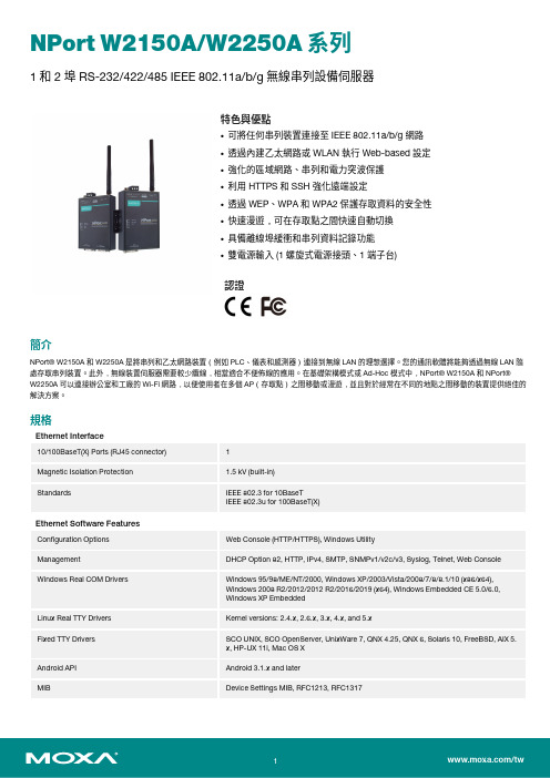
NPort W2150A/W2250A系列1和2埠RS-232/422/485IEEE802.11a/b/g無線串列設備伺服器特色與優點•可將任何串列裝置連接至IEEE802.11a/b/g網路•透過內建乙太網路或WLAN執行Web-based設定•強化的區域網路、串列和電力突波保護•利用HTTPS和SSH強化遠端設定•透過WEP、WPA和WPA2保護存取資料的安全性•快速漫遊,可在存取點之間快速自動切換•具備離線埠緩衝和串列資料記錄功能•雙電源輸入(1螺旋式電源接頭、1端子台)認證簡介NPort®W2150A和W2250A是將串列和乙太網路裝置(例如PLC、儀表和感測器)連接到無線LAN的理想選擇。
您的通訊軟體將能夠透過無線LAN隨處存取串列裝置。
此外,無線裝置伺服器需要較少纜線,相當適合不便佈線的應用。
在基礎架構模式或Ad-Hoc模式中,NPort®W2150A和NPort®W2250A可以連接辦公室和工廠的Wi-Fi網路,以便使用者在多個AP(存取點)之間移動或漫遊,並且對於經常在不同的地點之間移動的裝置提供絕佳的解決方案。
規格Ethernet Interface10/100BaseT(X)Ports(RJ45connector)1Magnetic Isolation Protection 1.5kV(built-in)Standards IEEE802.3for10BaseTIEEE802.3u for100BaseT(X)Ethernet Software FeaturesConfiguration Options Web Console(HTTP/HTTPS),Windows UtilityManagement DHCP Option82,HTTP,IPv4,SMTP,SNMPv1/v2c/v3,Syslog,Telnet,Web Console Windows Real COM Drivers Windows95/98/ME/NT/2000,Windows XP/2003/Vista/2008/7/8/8.1/10(x86/x64),Windows2008R2/2012/2012R2/2016/2019(x64),Windows Embedded CE5.0/6.0,Windows XP EmbeddedLinux Real TTY Drivers Kernel versions:2.4.x,2.6.x,3.x,4.x,and5.xFixed TTY Drivers SCO UNIX,SCO OpenServer,UnixWare7,QNX4.25,QNX6,Solaris10,FreeBSD,AIX5.x,HP-UX11i,Mac OS XAndroid API Android3.1.x and laterMIB Device Settings MIB,RFC1213,RFC1317Security HTTPS/SSL,User Authentication Management:local database,RADIUS,SecureProtocols:HTTPS(TLSv1.2),SSH,SNMPv3,Cryptography:HMAC,SHA-1,SHA-256,SHA-384,RSA-1024,AES-128,AES-256Time Management NTP Client,SNTP ClientWLAN InterfaceWLAN Standards802.11a/b/g/nReceiver Sensitivity for802.11a(measured at5.680 GHz)Typ.-91@6Mbps Typ.-74@54MbpsReceiver Sensitivity for802.11b(measured at2.437 GHz)Typ.-92dBm@1Mbps Typ.-84dBm@11MbpsReceiver Sensitivity for802.11g(measured at2.437 GHz)Typ.-91dBm@6Mbps Typ.-73dBm@54MbpsReceiver Sensitivity for802.11n(2.4GHz;measured at2.437GHz)Typ.-89dBm@6.5Mbps(20MHz) Typ.-71dBm@72.2Mbps(20MHz)Receiver Sensitivity for802.11n(5GHz;measured at 5.680GHz)Typ.-89dBm@6.5Mbps(20MHz) Typ.-71dBm@72.2Mbps(20MHz) Typ.-85dBm@13.5Mbps(40MHz) Typ.-67dBm@150Mbps(40MHz)Modulation Type DSSSOFDMTransmission Distance Up to100meters(in open areas) Transmission Rate802.11a/g:54Mbps802.11b:11Mbps802.11n:6.5to150Mbps Transmitter Power for802.11b16±1.5dBm@1Mbps16±1.5dBm@11Mbps Transmitter Power for802.11g16±1.5dBm@6Mbps14±1.5dBm@54Mbps Transmitter Power for802.11a15±1.5dBm@6Mbps14±1.5dBm@54Mbps Transmitter Power for802.11n(2.4GHz)16dBm@1.5Mbps(6.5MHz)12dBm@1.5Mbps(72.2MHz) Transmitter Power for802.11n(5GHz)15dBm@1.5Mbps(6.5MHz)12dBm@1.5Mbps(150MHz) Frequency Band for CN(20MHz operating channels) 2.412to2.472GHz(13channels)5.180to5.240GHz(4channels)5.260to5.320GHz(4channels)15.745to5.825GHz(5channels) Frequency Band for EU(20MHz operating channels) 2.412to2.472GHz(13channels)5.180to5.240GHz(4channels)5.260to5.320GHz(4channels)15.500to5.700GHz(11channels)1 Frequency Band for JP(20MHz operating channels) 2.412to2.484GHz(14channels)5.180to5.240GHz(4channels)5.260to5.320GHz(4channels)15.500to5.700GHz(11channels)1 Frequency Band for US(20MHz operating channels) 2.412to2.462GHz(11channels)5.180to5.240GHz(4channels)5.260to5.320GHz(4channels)25.500to5.700GHz(11channels)25.745to5.825GHz(5channels)Wireless Security WEP encryption(64-bit and128-bit)WPA/WPA2-Enterprise(IEEE802.1X/RADIUS,TKIP,AES)WPA/WPA2-PersonalWLAN Modes Ad-hoc Mode,Infrastructure modeSerial InterfaceConnector DB9maleNo.of Ports NPort W2150A/W2150A-T:1NPort W2250A/W2250A-T:2Serial Standards RS-232,RS-422,RS-485Operation Modes Real COM mode,TCP Server mode,TCP Client mode,UDP mode,RFC2217mode,PairConnection mode,Ethernet Modem mode,DisabledBaudrate50bps to921.6kbpsData Bits5,6,7,8Stop Bits1,1.5,2Parity None,Even,Odd,Space,MarkFlow Control None,RTS/CTS,XON/XOFFRS-485Data Direction Control ADDC®(automatic data direction control)Pull High/Low Resistor for RS-4851kilo-ohm,150kilo-ohmsTerminator for RS-485120ohmsSurge1kVPhysical CharacteristicsHousing MetalInstallation Desktop,DIN-rail mounting(with optional kit),Wall mountingDimensions(with ears,without antenna)77x111x26mm(3.03x4.37x1.02in)Dimensions(without ears or antenna)100x111x26mm(3.94x4.37x1.02in)Weight NPort W2150A/W2150A-T:547g(1.21lb)NPort W2250A/W2250A-T:557g(1.23lb)Antenna Length109.79mm(4.32in)Environmental LimitsOperating Temperature Standard Models:0to55°C(32to131°F)Wide Temp.Models:-40to75°C(-40to167°F)Storage Temperature(package included)-40to75°C(-40to167°F)Ambient Relative Humidity5to95%(non-condensing)Power ParametersInput Current NPort W2150A/W2150A-T:179mA@12VDCNPort W2250A/W2250A-T:200mA@12VDCInput Voltage12to48VDCStandards and CertificationsEMC EN55032/24EMI CISPR32,FCC Part15B Class AEMS IEC61000-4-2ESD:Contact:4kV;Air:8kVIEC61000-4-3RS:80MHz to1GHz:3V/mIEC61000-4-4EFT:Power:2kV;Signal:2kVIEC61000-4-5Surge:Power:2kV;Signal:1kVIEC61000-4-6CS:150kHz to80MHz:3V/m;Signal:3V/mIEC61000-4-8PFMFIEC61000-4-11Radio Frequency CE(ETSI EN301893,ETSI EN300328,ETSI EN301489-17,ETSI EN301489-1),ARIBRCR STD-33,ARIB STD-66ReliabilityAlert Tools RTC(real-time clock)Automatic Reboot Trigger Built-in WDTMTBFTime NPort W2150A/W2150A-T:383,187hrsNPort W2250A/W2250A-T:363,327hrsStandards Telcordia(Bellcore)Standard TR/SRWarrantyWarranty Period5yearsDetails See /tw/warrantyPackage ContentsDevice1x NPort W2150A/W2250A Series device serverPower Supply1x power adapter,suitable for your region(standard temp.models only)Antenna1x2.4/5GHz antennaDocumentation1x quick installation guide1x warranty card尺寸訂購資訊Model Name No.of serial portsWLAN Channels Input Current Operating Temp.Power Adapter inBox Notes NPort W2150A-CN 1China bands 179mA @12VDC 0to 55°C Yes (CN plug)—NPort W2150A-EU 1Europe bands 179mA @12VDC 0to 55°C Yes (EU/UK/AUplug)—NPort W2150A-EU/KC 1Europe bands 179mA @12VDC 0to 55°C Yes (EU plug)KC certificateNPort W2150A-JP 1Japan bands 179mA @12VDC 0to 55°C Yes (JP plug)—NPort W2150A-US 1US bands 179mA @12VDC 0to 55°C Yes (US plug)—NPort W2150A-T-CN 1China bands 179mA @12VDC -40to 75°C No —NPort W2150A-T-EU 1Europe bands 179mA @12VDC -40to 75°C No —NPort W2150A-T-JP 1Japan bands 179mA @12VDC -40to 75°C No —NPort W2150A-T-US 1US bands 179mA @12VDC -40to 75°C No —NPort W2250A-CN 2China bands 200mA @12VDC 0to 55°C Yes (CN plug)—NPort W2250A-EU 2Europe bands 200mA @12VDC 0to 55°C Yes (EU/UK/AUplug)—NPort W2250A-EU/KC 2Europe bands 200mA @12VDC 0to 55°C Yes (EU plug)KC certificateNPort W2250A-JP 2Japan bands 200mA @12VDC 0to 55°C Yes (JP plug)—NPort W2250A-US 2US bands 200mA @12VDC 0to 55°C Yes (US plug)—NPort W2250A-T-CN 2China bands 200mA @12VDC -40to 75°C No —NPort W2250A-T-EU 2Europe bands 200mA @12VDC -40to 75°C No —NPort W2250A-T-JP 2Japan bands 200mA @12VDC -40to 75°C No —NPort W2250A-T-US2US bands200mA @12VDC-40to 75°CNo—配件(選購)AntennasANT-WDB-ARM-02 2.4/5GHz,omni-directional rubber duck antenna,2dBi,RP-SMA(male)CablesCBL-F9M9-150DB9female to DB9male serial cable,1.5mCBL-F9M9-20DB9female to DB9male serial cable,20cmConnectorsADP-RJ458P-DB9F DB9female to RJ45connectorMini DB9F-to-TB DB9female to terminal block connectorDIN-Rail Mounting KitsDK35A DIN-rail mounting kit,35mmPower AdaptersPWR-12050-WPAU-S1Locking barrel plug,12VDC,0.5A,100-240VAC,Australia(AU)plug,0to40°C operating temperature PWR-12050-WPCN-S1Locking barrel plug,12VDC,0.5A,100to240VAC,China(CN)plug,0to40°C operating temperature PWR-12050-WPEU-S1Locking barrel plug,12VDC,0.5A,100-240VAC,Continental Europe(EU)plug,0to40°C operatingtemperaturePWR-12050-WPUK-S1Locking barrel plug,12VDC,0.5A,100-240VAC,United Kingdom(UK)plug,0to40°C operatingtemperaturePWR-12050-WPUSJP-S1Locking barrel plug,12VDC,0.5A,100-240VAC,United States/Japan(US/JP)plug,0to40°C operatingtemperaturePWR-12150-AU-SA-T Locking barrel plug,12VDC,1.5A,100-240VAC,Australia(AU)plug,-40to75°C operating temperatureApplicable Models:NPort W2150A-TNPort W2250A-TPWR-12150-CN-SA-T Wide-temperature(-40to75°C)locking barrel plug,12VDC,1.5A,100to240VAC,China(CN)plugApplicable Models:NPort W2150A-TNPort W2250A-TPWR-12150-EU-SA-T Locking barrel plug,12VDC,1.5A,100-240VAC,Continental Europe(EU)plug,-40to75°C operatingtemperatureApplicable Models:NPort W2150A-TNPort W2250A-TPWR-12150-UK-SA-T Locking barrel plug,12VDC,1.5A,100-240VAC,United Kingdom(UK)plug,-40to75°C operatingtemperatureApplicable Models:NPort W2150A-TNPort W2250A-TPWR-12150-USJP-SA-T Locking barrel plug,12VDC1.5A,100-240VAC,United States/Japan(US/JP)plug,-40to75°Coperating temperatureApplicable Models:NPort W2150A-TNPort W2250A-TPower CordsCBL-PJ21NOPEN-BK-30Locking barrel plug to bare-wire cable©Moxa Inc.版權所有.2021年1月25日更新。
ANTCOR 蚂蚁系列网络产品 2.4GHz超级无线终端机 说明书
目录ANTCOR蚂蚁系列网络产品 (1)2.4GHz 超级无线终端机车 (1)一、产品概述 (3)二、液晶配置 (5)2.1欢迎界面 (5)2.2屏幕菜单 (5)2.2.1设备信息 (5)2.2.2无线信息 (6)2.2.3无线扫描 (6)2.2.4学习过程 (7)2.2.5恢复出厂设置 (7)三、WEB页面配置 (8)3.1本地设置 (8)3.2登录设备 (8)3.3无线模式介绍 (9)3.3.1站点模式设置 (10)3.3.2中继模式设置 (12)3.3.3 3G无线路由器模式设置 (13)3.3.4无线路由器PPPoE设置 (14)3.3.5无线路由器设置 (15)3.4如何设置学习过的信息 (17)3.5高级设置 (19)3.6系统服务 (19)3.7系统设置 (19)3.8论坛 (22)附录A:无线安全设置说明 (22)附录B:无线工具使用说明 (23)7.1校正天线 (24)7.2 Ping (24)7.3跟踪路由 (24)7.4站点侦测 (25)附录C:FAQ(蚂蚁战车无线问答) (25)声明未经过本公司明确书面许可,任何单位或者个人不得擅自仿制、复制、眷抄或译本部分或者全部内容。
不得以任何形式或方法进行商品传播或用于任何商业、赢利目的。
本手册所提到的产品规格和资讯仅供参考,如内容有更新,恕不另行通知。
除非有特殊约定,本手册仅做为使用指导,本手册中的所有陈述,信息等均不构成任何形式的担保。
一、产品概述感谢您使用本公司ANTCOR蚂蚁系列网络产品2.4GHz 超级无线终端机(蚂蚁战车)。
这份手册将会帮助您完成所有的安装使用。
本包装内应该包含下列对象:2.4GHz 超级无线终端机(蚂蚁战车)5dBi天线5V、2A电源交叉网线保修卡注意:如有缺少请与经销商联系。
ANTCOR蚂蚁系列网络产品室内型超级无线终端机(蚂蚁战车),工作在2.4GHz频段,符合IEEE802.11b/g标准,采用OFDM(正交频分复用)技术,实际数据速率高达20Mbps 以上,具有速率高、传输距离远等特点,是小区无线覆盖/农村无线覆盖/校园无线覆盖/无线城市覆盖应用的最佳选择。
国威WSA型程控交换机说明书
目录第一章用户手册简介............................................................................................ 第二章产品概述....................................................................................................2.1产品简介 .........................................................................................................2.2特点.............................................................................................................2.3交换机语音..................................................................................................... 第三章技术要求......................................................................................................3.1技术要求 .........................................................................................................3.1.1容量 ..........................................................................................................3.1.2接口类型 ..................................................................................................3.1.3外设接口 ................................................................. 错误!未定义书签。
无线数据终端怎么使用
无线数据终端怎么使用无线数据终端是一种便捷的设备,用于在没有固定网络连接的环境下进行数据通信。
它可以通过无线网络与其他设备进行通信,并实现数据传输和接收的功能。
无线数据终端的使用方法相对简单,本文将介绍无线数据终端的基本用法以及注意事项。
首先,使用无线数据终端之前,我们需要确认一些基本的配置信息。
无线数据终端通常需要连接到一个无线网络,因此我们需要确保终端设备的无线功能已经开启,并正确的连接到一个可用的无线网络上。
通常,无线数据终端会提供一个配置界面,我们可以在配置界面中输入无线网络的名称(SSID)和密码,以便连接到网络。
在输入完毕后,保存配置并等待终端设备重新连接到网络。
当无线数据终端成功连接到无线网络后,我们可以开始使用它进行数据通信。
无线数据终端通常支持多种数据传输协议,如HTTP、FTP和TCP/IP等。
根据实际需求,我们可以选择合适的协议来进行数据传输。
下面将介绍几种常见的数据传输协议的使用方法。
首先,HTTP是一种常用的数据传输协议,用于在客户端和服务器之间传输数据。
无线数据终端可以作为一个HTTP客户端,从服务器上获取数据,或者将数据发送到服务器上。
我们可以使用终端设备上的浏览器来访问一个特定的URL,以获取服务器上的数据。
也可以使用HTTP客户端库来编写一个自定义的应用程序,实现数据的传输和接收。
其次,FTP是一种用于文件传输的协议,它可以用于将文件从一个设备传输到另一个设备上。
无线数据终端可以作为FTP客户端,从FTP服务器上下载或上传文件。
我们可以使用终端设备上的FTP客户端软件,输入FTP服务器的地址、用户名和密码,以及要下载或上传的文件名或路径,来完成文件传输的操作。
另外,TCP/IP是一种广泛使用的网络协议,用于实现数据的传输和接收。
无线数据终端可以使用TCP/IP协议与其他设备进行通信。
我们可以编写一个基于TCP/IP协议的应用程序,实现数据的传输和接收。
通过指定目标设备的IP地址和端口号,我们可以建立一个TCP/IP连接,并在连接上发送和接收数据。
4G 无线直流电压电流采集器器产品说明书
【上海数采物联网科技有限公司】无线电压电流采集器产品说明书版本:V1.1目录1产品概述 (1)2服务理念 (2)3产品特性参数 (3)3.1采集特性 (3)3.2电气特性 (3)3.3通信特性 (3)3.4结构特性 (3)3.5工作环境 (3)4产品核心优势 (4)5数据上报通信协议 (5)5.1协议解析说明 (5)5.2协议接收测试 (5)5.3协议定制 (5)6平台对接 (6)6.1默认平台 (6)6.2用户指定平台 (6)7注意事项 (7)1产品概述SC-GP-VC4G无线直流电压电流采集器,是上海数采物联网科技有限公司推出的一款基于4G网络通讯,将电压电流信号转化为数字信号,由无线模块传送到服务器的工业监测设备,电压电流传感器采用进口隔离霍尔元件,采集精度高,稳定性好,采集精度达0.1%,广泛应用于多种工业与民用场景,例如直流屏、光伏产业、测试及检测设备、消费品、汽车、地铁、自动控制、数据记录器、气象站、家电、医疗、电力及其他相关工业检测控制。
2服务理念我司郑重承诺:您购买的不仅仅是产品,还有细致、周到的技术支持服务(=^_^=)本产品,现场只需普通工人接电安装即可!无需调试!我们免费提供远程指导,远程配置调试服务,将数据发送至用户指定的云平台。
免费提供物联网方案咨询服务!3产品特性参数3.1采集特性●电压精度0.01V/±0.1%,电流0.01A/±0.5%●电压范围0-200V,电流范围0-100A●电流采集非侵入式,电压采集并联采集3.2电气特性●供电方式:12V直流供电(电源接口:DC5.5*2.1mm母头插座,内正外负)●工作功耗:小于5W3.3通信特性无线传输方式:4G/GPRS通信协议:MQTT/TCP/UDP/HTTP/SSL/ModBus RTU,可定制其他协议数据转发:任意公网服务器服务器中心数量:最多可支持同时向7个云服务器同时上报数据。
心跳包:支持自定义心跳包,可设置为信号强度。
- 1、下载文档前请自行甄别文档内容的完整性,平台不提供额外的编辑、内容补充、找答案等附加服务。
- 2、"仅部分预览"的文档,不可在线预览部分如存在完整性等问题,可反馈申请退款(可完整预览的文档不适用该条件!)。
- 3、如文档侵犯您的权益,请联系客服反馈,我们会尽快为您处理(人工客服工作时间:9:00-18:30)。
WD-HH-A无线数据通信综合终端
WD-HH-A无线数据通信综合终端(以下简称综合终端)融合了短波、人防3G专网等多种无线通信方式,集语音通信、文件传输、短消息传输、传真收发、北斗GPS传输等多种通信业务于一体,适合于人防指挥控制系统的车台、固定站安装使用。
综合终端充分利用人防已建成的短波、人防3G、卫星等无线通信链路,将原本各自相互独立的通信系统有机整合到一张网、一个平台,构造一个多网络、多路由、覆盖各级民防固定指挥所及机动指挥通信车的无线融合数据传输网络,满足了各级民防平时训练、演习,战时防空、灾时应急指挥协同对文电、数据、传真及定位的通信需求。
一、系统功能
配合无线融合数据通信软件,无线融合数据传输系统具有如下功能:1、综合终端对接短波电台,可实现短波方式文件和短消息点对点、
点对多点及广播方式收发;
2、综合终端内置3G模块,借助人防3G专网可实现文件和短消息
点对点、点对多点及广播方式收发;
3、综合终端对接传真机,借助人防3G专网或短波通信网,实现
传真文件收发;
4、综合终端对接北斗系统,借助人防3G专网,可实现对车台的
定位跟踪,克服了北斗短消息业务发送间隔长、延时不确定、
定位跟踪不连续等问题;
5、系统具有多种链路无线数据传输协议,各通信业务可以人工或
自动选择通信链路,增强了系统的灵活性和可靠性;
6、具有设备自检及工作状态指示功能。
二、系统组成
系统由短波通信网、人防3G专用通信网、北斗GPS构成,综合
终端结合无线融合数据通信软件,将这些无线网络进行有机整合,融合到一个通信平台,如下图所示:
图1 无线融合数据通信系统结构示意图
综合终端采用1U 标准化机箱结构,易于安装。
内部集成了传真卡、短波高速调制解调器、3G 通信模块、多串口服务器及交直流电源和状态指示等部分,配有与计算机、传真机、HF (短波)电台、VHF (超短波)电台及北斗GPS 系统的接口,集短波、人防3G 专网等多种无线通信方式于一体,具有语音通信、文件传输、传真收发及短消息传输、北斗定位及控制信息传输等功能。
三、无线融合数据通信软件
WD-HH-A 无线通信规程是针对综合终端开发的上层控制软件,实现系统各种资源的调度、各种无线通信方式的优化管理及文件、传真数据、短信息、定时信息的传输规程和通信过程监控等功能。
3G 综合终端
3G 综合终端 北斗GPS 车台
PC 超短波 短波 固定站PC
超短波 短波
传真机 传真机
图3 WD-HH-A无线通信规程1、短波功能
短波通信主要完成下述功能:
1)点对点文件收发
2)广播文件发送
3)组播文件发送
4)文件续收续发
5)短信收发
图4 短波功能2、3G功能
3G通信主要完成下述功能:
1)点对点文件收发
2)广播文件发送
3)组播文件发送
4)短信收发
图5 3G功能
3、传真功能
传真数据通信主要完成下述功能:
1)接收传真单元上传的传真数据,通过3G或短波(用户可选择)方式发送到目标站点;
2)将收到的远端传真数据,下载到本地终端,打印传真;
3)缓存传真数据,择时发送、或打印;
4、其他功能
其他功能包括:
1)转发车台北斗GPS定位信息至GIS平台,跟踪行驶轨迹;
2)参数设置
3)状态监测
4)日志查询
图6 转发车台北斗GPS定位信息至GIS平台
四、综合终端前后面板及配置
1、前面板
(1) ON/OFF 电源开关
(2)正常/配置拨向“正常”端表示普通状态;拨向“配置”端表示配置3G模块参数
(3) 3V 灯亮表示终端机传真模块上电
(4) 3G下“STA”灯亮表示终端机3G模块上线
(5) 3G下“TX”灯亮表示终端机3G模块向计算机发数据
(6) 3G下“RX”灯亮表示计算机向终端机3G模块发数据
(7) STA下“S1”预留
(8) STA下“S2”预留
(9) STA下“S3”预留
(10)GPS 灯亮表示有GPS数据传向终端机
(11)HF下“5V”灯亮表示终端机短波模块上电
(12)HF下“TX”灯亮表示终端机短波模块向计算机发数据(13)HF下“RX”灯亮表示计算机向终端机短波模块发数据(14)HF下“TM”灯亮表示PTT工作,电台处于发送状态(15)HF下“RV”灯亮表示终端机短波模块接收已同步
2、后面板
(1)H F 短波接口
(2)G PS GPS接口
(3)V HF 超短波接口
(4)3G 3G天线接头
(5)L INE 外接打印机电话线接口
(6)U SB 终端机和电脑USB连接接口,实现USB转多串口(7)A C220V 交流220V供电插座
(8)G ND 地柱。