林肯DC1000焊机中文说明书
林肯DC---1000+LN--7技术协议

DC—1000埋弧自动焊技术协议甲方(需方)博世热力技术(武汉)有限公司乙方(供方)武汉肯比焊接技术有限公司关于甲方订购1台林肯DC-1000埋弧焊电源,事宜,甲乙双方本着平等互利的原则,就本设备技术问题达成以下协议:1. 设备名称:埋弧自动焊接系统2. 设备规格型号:根据用户对焊接的要求及工件情况,设备配置如下:林肯DC-1000埋弧焊电源1台LT-7轨道式自动送丝机1套3. 设备技术条件3.1 设备用途:埋弧焊自动焊接3.2 主要技术参数:3.2.1 详细说明加工对象的要求、范围3.2.2 设备的详细技术参数(含遵循的技术标准/规范)(一)林肯DC--1000埋弧焊电源额定工作电流1000A额定负载持续率100%输入电源AC三相380V±10%50HZ±2%输出电流范围150——1300A空载电压Max75V接头开关NA---3电源电压调节范围16——46V(二)LT-7轨道式自动送机产品名称LT-7轨道式输入电源115V交流50/60HZ额定输出电流/暂载率600A/100%1100A/100%送丝速度范围 2.5~10.2m/min (100~400英寸/分)行走速度范围0.2~1.8m/min (6~70英寸/分)垂直机头升降调节范围12.7~127mm (1/2~5英寸/分)焊丝尺寸范围 2.4~4.8mm (3/32~3/16英寸)任一侧焊接角与垂直方向最大夹角50°制动角与垂直方向最大夹角30°3.2.3 设备其它技术指标(无)3.3 设备的组成及说明(一)林肯DC--1000埋弧焊电源1、美国林肯DC—1000整流器为六相可控硅半桥弧焊整流器,采用单旋钮电位器控制,应用于半自动和全自动焊接,电弧特性为平特性和降特性两种,可实现单一电源多种用途焊接。
2、DC---1000弧焊整流器适应自动埋弧焊电源,也可做手工弧焊电源、MIG焊、药芯焊丝焊,并且也可以做碳棒直径高达5/8英寸(15.9mm)的碳弧气刨电源。
林肯焊机说明书
林肯焊机说明书Ⅰ.机械安装1.机头安装安装应牢固以防起弧时机头移动,注意机头与工作电缆应与地绝缘。
根据需要,可装在垂直调节器/水平调节器/行走小车上,所定的机头出厂前根据用户的订购模式安装送丝比率,当改变焊丝直径时需改变送丝轮和导向管。
对不同直径的焊丝需调节随动轮压力调节螺丝,焊丝分两档0.9-2.4mm和3.0-5.6mm。
根据需要调节,对较软的焊丝,压力宜小一点。
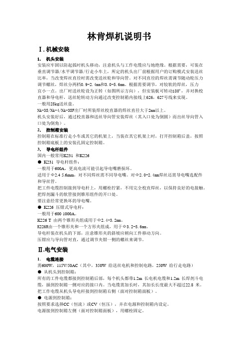
出厂时送丝轮设为正转(如图所示方向),但安装板可转动180º,并对换校直器和导电杆,送丝轮转动方向通过改变控制箱内接线上626,627号线来实现。
一般用25kg送丝盘。
NA-3S/NA-4/NA-3SF出厂时所装焊丝校直器的焊丝直径大于2mm以上。
机头安装好后,通过校直器和送丝导向管安装焊丝(其入口处为倒圆)而出丝导向管入口处为倒角)。
2.控制箱安装控制箱在标准行走小车或其它的机架上,当装在其它机架上时,打开控制箱后盖,按照控制箱底板上的安装孔固定控制箱。
3.导电杆组件国内一般常用K231 和K226●K231 导电杆组件:一般用于600A,更高电流可能引起导电嘴磨损坏。
适用于Ф2.4-5.6mm,对不同焊丝需不同导电嘴。
对Ф2.0-2.4mm焊丝还需导电嘴选配件和导丝管。
把工件电缆控制接到导电杆上,用螺栓拧紧,不用完全校直焊丝,以保持良好的电接触。
把焊剂漏斗的软管接到锥形组件的开口处。
要注意经常更换坏的导电嘴。
●K226 压钳式导电杆:一般用于600-1000A。
K226-T 由两个锥形夹组成用于Ф2.4-3.2mm。
K226R由一个锥形夹和一个方形夹组成,用于Ф3.2-5.6mm。
导电杆装在机头的下部,注意锥形夹的斜坡应朝向工件移动方向。
压钳应与导向管对直,通过调节夹钳一侧的螺丝来调节。
Ⅱ.电气安装1.电缆连接需600W,115V/50AC(其中,350W 给送丝电机和控制电路,250W 给行走电路)●从机头到控制箱:所有的工件电缆都接到控制箱后部,每个机头都带1.2m 长电机电缆和1.2m 长焊剂斗电缆,插到控制箱一侧对应的接口内。
DC1000系列数字控制器产品说明说明书

DC1010 - DC1020 - DC1030 - DC1040General Purpose DIGITAL CONTROLLERSPRODUCT SPECIFICATION SHEETDC1010 (1/16 DIN) DC1020 (1/8 DIN)OVERVIEWThe DC1000 family ofmicroprocessor based controllers combine a high degree offunctionality and reliability at a very low price. Available in 4 different formats : 1/16 DIN, 1/8 DIN, 3/16 DIN, 1/4 DIN. These controllers are ideal for regulating temperature in a variety of applications, including : x Dryers.x Semiconductor packaging /testing.x Plastic processing.x Packaging machinery.x Painting and coating.x Climatic chambers.The DC1000 family provides basic control requirements, plus advanced features such as motor position control, phase angle power control and Setpoint programming.FEATURESDC1030 (3/16 DIN)DC1040 (1/4 DIN)Easy to configureTwo different configuration levels provide easy access to parameters. A 4-digit security code prevents unauthorized changes. Parameters can also be hidden to the user to prevent mis-configuration of the unit. Various Control algorithms The DC1000 series of controllers provide several different algorithms: x PID or ON/OFF control.x Heat/Cool algorithms with 2different PID sets.x Motor position control withoutslidewire feedback.x Single phase control, with orwithout zero crossover control. x Three phase control, with orwithout zero crossover control.Dual display and BargraphTwo large 4 digits displays and one 10 LED bargraph display PV, SP andconfiguration parameters. Up to 8 LEDs display the status of the different Outputs (Control, Alarm, …) and also provides indication of the Auto/Manual and Programmer states.Setpoint ProgrammingTwo programs are available, with amaximum of 8 segments. The 2 programs can be linked together to form a single 16 segment program.Extended Alarm capability Three different alarm outputs areavailable per instrument, 17 alarm modes are configurable.CommunicationsRS232 or RS485 ASCII protocol is optionally available. Up to 30 DC1000 Controllers can be connected to a single host computer. The host computer can change the SP, monitor the PV, the output or change the configuration of the unit.Remote Setpoint capability. Manual / Automatic modes. Universal Power supplyOperates on any voltage from85Vac to 265Vac at 50/60Hz. Large operating rangeThese instruments can operate from –20°C to +65°CSPECIFICATIONSThermocouples : K, J, R, S, B, E, N, T, W, PL II, U, L Type of InputRTD : Pt100, JPt100, JPt50PV InputLinear : 4~20mAInput Sampling Time 500 msInput Resolution 14 bit (each)PV/SP Indication 4-digit, 7 segment displayIndicationConstant Value Storage System Non-volatile memory (E2PROM)Indication Accuracy 0.5%FSProportional Band ( P ) 0~200% (On/Off action at P=0)Integral Time ( I ) 0~3600 sec (PD action at I=0)Control ModeDerivative Time ( D ) 0~900 sec (PI action at D=0)Cycle Time 0~150 sec (4~20mA=0, SSR=1, Relay=10)Dead Band Time 0~1000 sec (dead time compensation)Relay Output Electromechanical relayx SPDT contactsx 3A/240VacStatic relay driver output Voltage Pulse, 20VDC/20mAOutputCurrent & Voltage outputs 0~20mA, 4~20mA,0~5V, 0~10V, 1~5V, 2~10VMotor Control Output Servo motor valve control (open loop circuit)Others Phase angle control :9 1M SSR, 3M SSR, 1M SCR, 3M SCRNumber Up to 3 (optional)Modes 17 alarm modes available, hability to ignore the alarmthe first time it occurs :9 Deviation high or low alarms.9 Deviation alarms.9 Band alarm.Alarm9 High or low alarm.9 End of segment alarm.9 Program run indication alarm.9 Timer alarm.Timer One timer is associated with each alarm.Output Signal SP, PVRetransmissionoutput Type of Output 4~20mA, 0~20mA, 0~5V, 0~10V, 1~5V, 2~10VType of Input4~20mA, 0~20mA, 0~5V, 0~10V, 1~5V, 2~10V 2nd Input (Remote SP) Sampling Time 500 ms.Programs Number2 programs of 8 segments each. CommunicationType of CommunicationRS-232 or RS-485. ASCII protocol.Rated Power Supply Voltage & FrequencyAC 85 ~ 265V, 50/60Hz Power Consumption 8VA (110V), 12VA (220V) Ambient Temperature -20°C ~ 65°C (-4°F ~ 149°F) Operating conditionsAmbient Humidity50 ~ 85% RH (non condensing) ApprovalsUL Pending. CE Mark.x PID or ON/OFF control.x Heat/Cool algorithms with 2 different PID sets.x Phase angle controlSingle PhaseThree Phase3I LOADIn phase angle control, power is regulated by changing the point at which the SCR is turned on within each 1/2 period. Single Phase : Output is changed every half-cycle in response to output signals from the Temperature Controller. Three Phase : The outputs are changed every 120° in response to signals from the Temperature Controller. Using this form of control, high-precision temperature control is possible.x Zero-crossover controlSingle Phase1I LOADThree Phase3I LOADThe term Zero-Crossover means that the SCR's are turned on only when the instantaneous value of the sinusoidal wave is zero. Power is then applied for a several continuous half-cycles and then removed for several half-cycles to achieve the desired load power.x Motor position control without slidewire Feedback.MOTOR VALVEMotor position is achieved by using time proportional controlwithout the need for slidewire feedback from the motor shaft. Slidewires wear over a period of time, which can result in poor or intermittent control. This type of control reduces maintenance requirements and removes the need for the controller to be calibrated to the motor feed back potentiometer.DC101050 mm - 1.97 in74.5 mm - 2.97 in13.5 mm 0.53 in6 mm 0.24 in 44 m m - 1.73 i n50 m m - 1.97 i n68 mm - 2.68 in60 m m - 2.36 i n45.5 mm - 1.79 in 45.5 m m - 1.79 i nDC102074.5 mm - 2.97 in13.5 mm 0.53 in6 mm 0.24 in86 mm 3.39 in96 m m - 3.78 i n48 mm - 1.89 in60 mm - 2.36 in91mm 3.58 in45.5mm 1.79 in116 mm 4.57 inDC103074.5 mm - 2.97 in13.5 mm 0.53 in6 mm 0.24 in66 m m - 2.60 i n72 mm - 2.83 in72 m m - 2.83 i n91 mm - 3.58 in69.55 mm 2.74 in91 m m - 3.58 i n69.55 mm 2.74 inContact Details:Industrial Supply Syndicate54, Ezra Street, Kolkata - 700 001, INDIAPhone: 22350923, 22356676 Fax: 91-33-30222923。
林肯电焊机操作手册说明书

SP-100OPERA TOR'S MANUALFor use with machines having Code Number 9284 and above .Sales and Service through Subsidiaries and Distributors WorldwideWorld's Leader in Welding and Cutting Products Premier Manufacturer of Industrial MotorsIM366-BNovember 1993Safety Depends on YouLincoln arc welding equipment is designed and built wit h safet y in mind. However, your overall safety can be increased by proper instal-lat ion ... and t hought ful operat ion on your part.DO NOT INSTALL OPERATE OR REPAIR THIS EQUIPMENT WITHOUT READ-ING THIS MANUAL AND THE SAFETY PRECAUTIONS CON-TAINED THROUGHOUT.And,most importantly, think before you act and be careful.9284; 9429; 9521; 9522; 9725;9726; 9794; 9795; 10050Thank Youfor selecting a QUALITY product by Lincoln Electric.We want you to take pride in operating this Lincoln Electric C ompany product ••• as much pride as we have in bringing this product to you!Read this Operators Manual completely before attempting to use this equipment. Save this manual and keep it handy for quick reference. Pay particular attention to the safety instructions we have provided for your protection. The level of seriousness to be applied to each is explained below:PRODUCT DESCRIPTIONThe SP-100, Type K462, is a complete semiautomatic constant voltage DC arc welding machine. Included is a solid state controlled, single phase constant voltage transformer/ rectifier power source and a wire feeder for feeding .023 – .030" (0.6 – 0.8 mm) solid steel electrode and .035" (0.9 mm) cored electrode.The SP-100 is ideally suited for individuals having access to 115 volt AC input power, and wanting the ease of use, quality and dependability of both gas metal arc welding or GMAW (also known as MIG welding) and the Innershield®electrode process (self-shielded flux-cored or FC AW). A convenient chart is mounted inside the wire feed section door for setting welding procedures for 24 gauge through 12 gauge (0.6 – 2.5 mm) mild steel (Chart also may be found in this manual). The SP-100 is a rugged and reliable machine that has been designed for dependable ser-vice and long life.RECOMMENDED PROCESSES AND EQUIPMENTThe SP-100 can be used for welding mild steel using the GMAW, single pass, process which requires a supply of shielding gas or it can be used for the self-shielded, Innershield electrode process.The recommended gas and electrode for GMAW is welding grade CO2gas and .025" (0.6 mm) diameter Lincoln L-56 mild-steel welding wire [supplied on 12 1/2 lb (6 kg) spools]. For 14 gauge (2.0 mm) and thin-ner, CO2gas is recommended because it gives equal or better performance than a blended gas at a lower cost. A mixed gas consisting of 75 to 80% Argon and 20 to 25% CO2is recommended for welding on heav-ier gauge [12 gauge (2.5 mm) for example] steel.The recommended electrode for the self-shielded process is .035" (0.9 mm) diameter Lincoln Innershield NR-211-MP on 10 lb (4.5 kg) spools. This electrode can be used for all position welding of 20 gauge through 5/16" (1.0 – 8.0 mm) thick steel [multi-ple passes are required for 1/4" and 5/16" (6.0 and 8.0 mm)].OPTIONAL ACCESSORIES1.K463 CO2G as Regulator and Hose Kit—Includes a preset, nonadjustable pressure and flow regulator for use on C O2cylinders. Also included is a 10 foot (3.0 m) gas hose which con-nects to the rear of the SP-100.2.K499 Ar-Mixed Gas Regulator and Hose Kit—Includes a preset, nonadjustable pressure and flow regulator for use on argon-mixed gas cylin-ders. Also included is a 10 foot (3.0 m) gas hose which connects to the rear of the SP-100.3..035 (0.9 mm) Innershield®Welding Kit —Includes a contact tip, a gasless nozzle and a cable liner to permit the SP-100 gun and cable to use a .035" (0.9 mm) diameter flux-cored elec-trode. Also included is a spool of .035 (0.9 mm) Innershield®NR-211-MP.Two kits are available:K549-1 kit is for use with the Magnum™100L gun (with red trigger).K464 kit is for use with the original Lincoln Electric®gun (with black trigger).4.M15448-1 Reversible Drive Roll with doubleknurled grooves for .035 cored electrode.5.K467 Input Line Cord — Same as line cord sup-plied with the SP-100 but has a NEMA type 5-20P plug for use on 25 amp branch circuits.To install optional features refer to instructions included with the kit, and/or in this manual.INSTALLATIONDESCRIPTION OF CONTROLSBecome familiar with the SP-100 controls and compo-nents before attempting to weld. Refer to illustrations and lettered items below for brief descriptions.A.Wire speed — Controls the wire speed from 50 –400 in./min (1.3 – 10 m/min). The control can be preset on the dial to the setting specified on the SP-100 Application Chart located on the inside of the wire feed section door. Wire speed is not affected when changes are made in the voltage control. The control is marked (“olo”)B.Power ON/OFF switch — When the power is on,the fan motor will run and air will be exhausted out the louvers in the front of the machine. The welding output and wire feeder remain off until the gun trigger is pressed.C.Voltage control — A continuous control that givesfull range adjustment of power source output volt-age. Can be adjusted while welding.D.Thumbscrew — secures gun and cable assembly.E.Positive (+) and negative (–) output terminals.F.Shielding gas hose (factory installed, not shown)— routed from gas solenoid inside rear of machine to gun connector block.G.Gun trigger lead connectors.H.Circuit breaker — Protects machine from damageif maximum output is exceeded. Button will extend out when tripped. (Manual reset.)I.Wire spool spindle.J.Gas solenoid inlet fitting.K.Power cord.L.Spring loaded pressure arm — adjusts pressureof idle roll on wire.M.Wire feed gearbox and gun connector block.N.Wire feed section door — With application chartfor machine setting procedures.O.Gun cable and control lead access hole.P.Work cable access hole.LOCATIONLocate the welder in a dry location where there is free circulation of clean air into the louvers in the back and out the front. A location that minimizes the amount of smoke and dirt drawn into the rear louvers reduces the chance of dirt accumulation that can block air pas-sages and cause overheating.WORK CABLE AND CLAMP INSTALLATIONWork Clamp InstallationAttach the work clamp to the work cable per the fol-lowing:1.Unplug the machine or turn the power switch to the “Off” position.2.Insert the work cable terminal lug with the larger hole through the strain relief hole in the work clamp as shown below.3.Fasten securely with the bolt and nut provided.Work cableWork clampWork Cable Installation1.Open the wire feed section door on the right side ofthe SP-100.2.Pass the end of the work cable that has the termi-nal lug with the smaller hole through the hole (holeD) next to the louvers in the case front.3.Route the cable under and around the back of thewire feed unit.ing wing nut provided, connect the terminal lugto the negative (–) output terminal located above the wire feed unit; item M (make certain that both wing nuts are tight).NOTE: This connection gives the correct electrode polarity for the GMAW process. If using Innershield, see Output Polarity C onnection Section below for negative electrode polarity connection. OUTPUT POLARITY CONNECTIONThe SP-100, as shipped, is connected for positiveelectrode polarity.To connect for negative electrode polarity (required for the Innershield process), connect the short cable attached to the gun connector block to the negative (–) output terminal and the work cable to the positive (+) terminal using the provided wing nuts (make cer-tain that both wing nuts are tight).GUN INSTALLATIONAs shipped from the factory, the SP-100 gun is ready to feed .023, .024 or .025" (0.6 mm) wire. If .030" (0.8 mm) wire is to be used, install the .030" (0.8 mm) con-tact tip. .023 – .025" contact tip is stenciled .025 and/or 0.6 mm and .030" contact tip is stenciled .030 and/or 0.8 mm. See Maintenance Section for instruc-tions to change contact tip.If .035" (0.9 mm) Innershield flux cored wire is to be used, see Maintenance Section for instructions to change contact tip, cable liner, and gas nozzle.C onnect the gun cable to the SP-100 per the follow-ing:1.Unplug the machine or turn power switch to the off“O” position.2.Pass the insulated terminals of the gun trigger con-trol leads, one at a time, through the rectangular “keyhole” opening (item F) in the case front. The leads are to be routed under the wire feed unit and through the cable hanger on the inner panel.3.Insert the connector on the gun conductor cablethrough the large hole in the SP-100 case front.Make sure the connector is all the way in the metal connector block to obtain proper gas flow. Rotate the connector so control leads are on the underside and tighten the thumbscrew in the connector block.4.Connect the insulated control lead terminals to thetwo insulated 1/4" (6.4 mm) tab connector bushings located above the “Gun Trigger C onnection” decal in the wire feed section. Either lead can go to either connector. Form the leads so that they are as close as possible to the inside panel.WIRE FEED DRIVE ROLLThe SP-100 drive roll has two grooves; one for .023 –.025" (0.6 mm) solid steel electrode and the other for .030" (0.8 mm) solid and .035" (0.9 mm) flux-cored steel electrode. As shipped, the drive roll is installed in the .023/.025" (0.6 mm) position (as indicated by the stenciling on the exposed side of the drive roll).Replace the washer and retaining screw.connectors{Brass connectorIdle roll armRetaining ScrewWELDING WIRE LOADINGThe machine power switch should be turned to the OFF (“O”) position before working inside the wirefeed enclosure.------------------------------------------------------------------------The machine is shipped from the factory ready to feed 8" (200 mm) diameter spools [2.2" (56 mm) max. width]. These spools fit on a 2" (50 mm) diameter spindle that has a built-in, adjustable* friction brake to prevent overrun of the spool and excess slack in theWARNINGK499 Argon-Mixed Gas Regulator and Hose Kit Install the pressure-flow regulator and gauge to a cylinder according to the instructions in Section 1.10.C onnect one end of the 10 foot (3.0 m) hose to the SP-100 gas inlet fitting and the other end to the regu-lator fitting.The K499 argon-mixed gas pressure-flow regulator is preset by the manufacturer to deliver a nominal flow of 30 cubic feet per hour (14 1/min) of argon or argon-mixed gas. This setting cannot be changed..035" (0.9 mm) Innershield Welding KitIncludes a contact tip, gasless nozzle, and a cable liner to permit the SP-100 gun and cable to use .035 (0.9 mm) diameter flux-cored electrode. Also included is a spool of .035 (0.9 mm) Innershield®NR-211-MP. The K549-1 Kit is for use with the Magnum™100L gun (with red trigger). The fitting on the end of the liner is stenciled with the maximum rated wire size (.045"/1.2 mm).The K464 Kit is for use with the earlier “Lincoln Electric®” gun (with black trigger). The end of the brass fitting on the end of the liner for .035 (0.9 mm) wire is color coded green. The .023-.030 (0.6-0.8 mm) factory installed liner is color coded orange.See Maintenance and Troubleshooting Section for instructions on installing liner and contact tip in gun.K467 Input Line CordSame as line cord supplied with the SP-100 but has a NEMA type 5-20P plug for use on a 25 amp branch circuit with a nominal voltage rating of 115 volts to 125 volts, 60 hertz. Install per the following:1.Turn the SP-100 Power Switch to OFF (“O”).2.If connected, remove the line cord plug from powersupply receptacle.3.Remove the two screws that hold the line cordreceptacle in the SP-100 flanged inlet connector and disconnect the line cord from the SP-100.4.C onnect the S18410 input line cord receptacle tothe SP-100 and replace the retaining screws.OPERATING INSTRUCTIONS1.Decrease stickout2.Increase WFS (wire feed speed) (“oIo”)3.Decrease voltage (“V”)4.Increase speed5.Decrease drag angle6.Check for correct gas, if usedIf Arc Blow Occurs (in order of importance) (NOTE: Try different ground connection locations before adjusting procedures)1.Decrease drag angle2.Increase stickout3.Decrease voltage (“V”)4.Decrease WFS (wire feed speed) (“oIo”) andvoltage (“V”)5.Decrease travel speedTo Eliminate Stubbing (in order of importance)1.Increase voltage (“V”)2.Decrease WFS (wire feed speed) (“oIo”)3.Decrease stickout4.Increase drag angleStubbing occurs when the electrode drives through the molten puddle and hits the bottom plate tending to push the gun up.PROPER GUN HANDLINGMost feeding problems are caused by improper han-dling of the gun cable or electrodes.1.Do not kink or pull the gun cable around sharp cor-ners.2.Keep the gun cable straight as practical when weld-ing.3.Do not allow dolly wheels or trucks to run over thecables.4.Keep the cable clean per maintenance instructionsin this Operation Manual.5.Innershield electrode has proper surface lubrica-tion. Use only clean, rust-free electrode.6.Replace the contact tip when it becomes worn orthe end is fused or deformed.Low or no gas flow Cylinder valve closed Open cylinder valveGas flow not set correctly Set proper flow rateCylinder out of gas Get new cylinder of gasLeak in gas line Inspect and replaceClog or Leak in gun Check for obstruction or defective sealsArc unstable Wrong welding polarity Check polarity - Refer to proper sectionErratic or Intermittent Wrong size, worn and/or Replace tip - remove any spatter on end of tip Arc - Poor Starting melted contact tip"Hunting" ArcWorn work cable or poor connections Inspect - repair or replace as necessaryLoose electrode connections Be sure electrode lead is tight, gun cable tight inwire feeder contact block, gun nozzle and guntip tightM 16576S P 100 W I R I N G D I A G R A MNow Available...12th Edition The Procedure Handbook of Arc WeldingWith over 500,000 copies of previous editions publishedsince 1933, the Procedure Handbook is considered by many tobe the “Bible” of the arc welding industry.This printing will go fast so don’t delay. Place yourorder now using the coupon below.The hardbound book contains over 750 pages of weldinginformation, techniques and procedures. Much of this materialhas never been included in any other book.A must for all welders, supervisors, engineers anddesigners. Many welding instructors will want to use the bookas a reference for all students by taking advantage of the lowquantity discount prices which include shipping by4th class parcel post.$15.00postage paid U.S.A. Mainland How To Read Shop Drawings The book contains the latest information and application data on the American Welding Society Standard Welding Symbols. Detailed discussion tells how engineers and draftsmen use the “short-cut” language of symbols to pass on assembly and welding information to shop personnel.Practical exercises and examples develop the reader’s abilityto visualize mechanically drawn objects as they will appearin their assembled form.187 pages with more than 100 illustrations. Size 8-1/2” x 11”Durable, cloth-covered board binding.$4.50postage paid U.S.A. Mainland New Lessons in Arc Welding Lessons, simply written, cover manipulatory techniques;machine and electrode characteristics; related subjects,such as distortion; and supplemental information on arc welding applications, speeds and costs. Practice materials,exercises, questions and answers are suggested for each lesson.528 pages, well illustrated, 6” x 9” size, bound in simulated,gold embossed leather.$5.00postage paid U.S.A. Mainland Need Welding Training?The Lincoln Electric Company operates the oldest andmost respected Arc Welding School in the United States at itscorporate headquarters in Cleveland, Ohio. Over 100,000stu-dents have graduated. Tuition is low and the training is“hands on”For details write: Lincoln Welding School 22801 St. Clair Ave.Cleveland, Ohio 44117-1199.and ask for bulletin ED-80 or call 216-383-2259 and ask for the Welding School Registrar.Lincoln Welding School BASIC COURSE$700.005 weeks of fundamentals There is a 10%discount on all orders of $50.00 or more for shipment at one time to one location.Orders of $50 or less before discount or orders outside of North America must be prepaid with charge, check or money order in U.S. Funds Only.Prices include shipment by 4th Class Book Rate for U.S.A. Mainland Only.Please allow up to 4 weeks for delivery.UPS Shipping for North America Only.All prepaid orders that request UPS shipment please add:$5.00For order value up to $49.99$10.00For order value between $50.00 & $99.99$15.00For order value between $100.00 & $149.00For North America invoiced orders over $50.00 & credit card orders, if UPS is requested, it will be invoiced or charged to you at cost.Outside U.S.A. Mainland order must be prepaid in U.S. Funds. Please add $2.00 per book for surface mail or $15.00 per book for air parcel post shipment.METHOD OF PAYMENT:(Sorry, No C.O.D. Orders)CHECK ONE:Name:_______________________________________________Please Invoice (only if order is over $50.00)Address:_______________________________________________Check or Money Order Enclosed, U.S. Funds only_______________________________________________Credit Card - Telephone:_______________________________________________Signature as it appears on Charge Card:Account No.Exp Date |_|_||_|_|______________________Month Year USE THIS FORM TO ORDER:Order from:BOOK DIVISION, The Lincoln Electric Company, 22801 St. Clair Avenue, Cleveland, Ohio 44117-1199BOOKS OR FREE INFORMATIVE CATALOGSTelephone: 216-383-2211 or, for fastest service, FAX this completed form to: 216-361-5901.Lincoln Welding School Titles:Price Code Quantity Cost (ED-80)New Lessons in Arc Welding $5.00L Seminar Information Procedure Handbook “Twelfth Edition”$15.00PH (ED-45)How to Read Shop Drawings $4.50H Educational Video Information Incentive Management $5.00IM (ED-93)A New Approach to Industrial Economics $5.00NA James F. Lincoln Arc WeldingThe American Century of John C. Lincoln $5.00AC Foundation Book Information Welding Preheat Calculator $3.00WC-8(JFLF-515)Pipe Welding Charts $4.50ED-89SUB TOTALAdditional Shipping Costs if anyTOTAL COSTJapaneseChineseKoreanArabicREAD AND UNDERSTAND THE MANUFACTURER’S INSTRUCTION FOR THIS EQUIPMENT AND THE CONSUMABLES TO BE USED AND FOLLOW YOUR EMPLOYER’S SAFETY PRACTICES.SE RECOMIENDA LEER Y ENTENDER LAS INSTRUCCIONES DEL FABRICANTE PARA EL USO DE ESTE EQUIPO Y LOS CONSUMIBLES QUE VA A UTILIZAR, SIGA LAS MEDIDAS DE SEGURIDAD DE SU SUPERVISOR.LISEZ ET COMPRENEZ LES INSTRUCTIONS DU FABRICANT EN CE QUI REGARDE CET EQUIPMENT ET LES PRODUITS A ETRE EMPLOYES ET SUIVEZ LES PROCEDURES DE SECURITE DE VOTRE EMPLOYEUR.LESEN SIE UND BEFOLGEN SIE DIE BETRIEBSANLEITUNG DER ANLAGE UND DEN ELEKTRODENEINSATZ DES HER-STELLERS. DIE UNFALLVERHÜTUNGSVORSCHRIFTEN DES ARBEITGEBERS SIND EBENFALLS ZU BEACHTEN.JapaneseChineseKoreanArabicLEIA E COMPREENDA AS INSTRUÇÕES DO FABRICANTE PARA ESTE EQUIPAMENTO E AS PARTES DE USO, E SIGA AS PRÁTICAS DE SEGURANÇA DO EMPREGADOR.(such as loss of business, etc.) caused by the defect or Sales and Service through Subsidiaries and Distributors Worldwide22801 St. Clair Ave. Cleveland, Ohio 44117-1199 U.S.A. Tel. (216) 481-8100Premier Manufacturer of Industrial Motorsd。
林肯电子焊接和切割产品说明书

Copyright © Lincoln Global Inc.LN ™- 25 PIPEIM10056April, 2011For use with machines having Code Number:11693Safety Depends on YouLincoln arc welding and cutting equipment is designed and built with safety in mind. However, your overall safety can be increased by proper installation ... and thoughtful operation on your part. DO NOT INSTALL, OPERATE OR REPAIR THIS EQUIPMENT WITHOUT READING THIS MANUAL AND THE SAFETY PRECAUTIONS CONTAINED THROUGHOUT.And, most importantly, think beforeyou act and be careful.IP23IEC 60974-5SECTION A:WARNINGSC ALIFORNIA PROPOSITION 65 WARNINGSWARNING: This product, when used for welding or cutting, produces fumes or gases which contain chemicals known to the State of California to cause birth defects and, in some cases, cancer. (California Health & Safety Code § 25249.5 et seq.)ARC WELDING CAN BE HAZARDOUS. PROTECTYOURSELF AND OTHERS FROM POSSIBLE SERIOUS INJURY OR DEATH. KEEP CHILDREN AWAY.PACEMAKER WEARERS SHOULD CONSULT WITH THEIR DOCTOR BEFORE OPERATING.Read and understand the following safety highlights. For additional safety information, it is strongly recommended that you purchase a copy of “Safety in Welding & Cutting - ANSI Standard Z49.1” from the American Welding Society, P.O. Box 351040, Miami, Florida 33135 or CSA Standard W117.2-1974. A Free copy of “Arc Welding Safety” booklet E205 is available from the Lincoln Electric Company, 22801 St. Clair Avenue, Cleveland, Ohio 44117-1199.BE SURE THAT ALL INSTALLATION, OPERATION,MAINTENANCE AND REPAIR PROCEDURES ARE PERFORMED ONLY BY QUALIFIED INDIVIDUALS.FOR ENGINE POWERED EQUIPMENT.1.a.Turn the engine off before troubleshootingand maintenance work unless themaintenance work requires it to be running.1.b.Operate engines in open, well-ventilated areas or vent the engineexhaust fumes outdoors. 1.c.Do not add the fuel near an open flame weldingwith hot engine parts and igniting. Do not spill fuel when filling tank. If fuel is spilled, wipe it up and do not start engine until fumes have been eliminated.1.d. Keep all equipment safety guards, coversand devices in position and in good repair.Keep hands, hair, clothing and tools away from V-belts, gears, fans and all other moving parts when starting, operating or repairing equipment.1.e.In some cases it may be necessary to remove safety guards toperform required maintenance. Remove guards only when necessary and replace them when the maintenance requiring their removal is complete. Always use the greatest care when working near moving parts. 1.f. Do not put your hands near the engine fan. Do not attempt tooverride the governor or idler by pushing on the throttle control rods while the engine is running. 1.g.To prevent accidentally starting gasoline engines while turningthe engine or welding generator during maintenance work,disconnect the spark plug wires, distributor cap or magneto wire as appropriate. 1.h.To avoid scalding, do not remove the radiatorpressure cap when the engine is hot.ELECTRIC ANDMAGNETIC FIELDS MAY BE DANGEROUS2.a.Electric current flowing through any conductorcauses localized Electric and Magnetic Fields (EMF).Welding current creates EMF fields around welding cables and welding machines 2.b.EMF fields may interfere with some pacemakers, andwelders having a pacemaker should consult their physician before welding. 2.c.Exposure to EMF fields in welding may have other health effectswhich are now not known. 2.d.All welders should use the following procedures in order tominimize exposure to EMF fields from the welding circuit:2.d.1.Route the electrode and work cables together - Securethem with tape when possible.2.d.2.Never coil the electrode lead around your body.2.d.3.Do not place your body between the electrode and workcables. If the electrode cable is on your right side, the work cable should also be on your right side.2.d.4.Connect the work cable to the workpiece as close as pos-sible to the area being welded.2.d.5.Do not work next to welding power source.SAFETYConformanceProducts displaying the CE mark are in conformity with European Community Council Directive of 15 Dec 2004 on the approximation of the laws of the Member States relating to electromagnetic compatibility,2004/108/EC. It was manufactured in conformity with a national standard that implements a harmonized standard: EN 60974-10 Electromagnetic Compatibility (EMC) Product Standard for Arc Welding Equipment. It is for use with other Lincoln Electric equipment. It is designed for industrial and professional use. IntroductionAll electrical equipment generates small amounts of electromagnetic emission. Electrical emission may be transmitted through power lines or radiated through space, similar to a radio transmitter. When emissions are received by other equipment, electrical interference may result. Electrical emissions may affect many kinds of electrical equipment; other nearby welding equipment, radio and TV reception, numerical controlled machines, telephone systems, computers, etc. Be aware that interference may result and extra precautions may be required when a welding power source is used in a domestic establishment.Installation and UseThe user is responsible for installing and using the welding equipment according to the manufacturer’s instructions. If electromagnetic disturbances are detected then it shall be the responsibility of the user of the welding equipment to resolve the situation with the technical assistance of the manufacturer. In some cases this remedial action may be as simple as earthing (grounding) the welding circuit, see Note. In other cases it could involve construction of an electromagnetic screen enclosing the power source and the work complete with associated input filters. In all cases electromagnetic disturbances must be reduced to the point where they are no longer troublesome.Note: The welding circuit may or may not be earthed for safety reasons according to national codes.Changing the earthing arrangements should only be authorized by a person who is compe-tent to access whether the changes will increase the risk of injury, e.g., by allowing parallelwelding current return paths which may damage the earth circuits of other equipment. Assessment of AreaBefore installing welding equipment the user shall make an assessment of potential electromagnetic prob-lems in the surrounding area. The following shall be taken into account:a) other supply cables, control cables, signaling and telephone cables; above, below and adjacent to thewelding equipment;b) radio and television transmitters and receivers;c) computer and other control equipment;d) safety critical equipment, e.g., guarding of industrial equipment;e) the health of the people around, e.g., the use of pacemakers and hearing aids;f) equipment used for calibration or measurementg) the immunity of other equipment in the environment. The user shall ensure that other equipment beingused in the environment is compatible. This may require additional protection measures;h) the time of day that welding or other activities are to be carried out.The size of the surrounding area to be considered will depend on the structure of the building and other activities that are taking place. The surrounding area may extend beyond the boundaries of the premises. Methods of Reducing EmissionsMains SupplyWelding equipment should be connected to the mains supply according to the manufacturer’s recommenda-tions. If interference occurs, it may be necessary to take additional precautions such as filtering of the mains supply. Consideration should be given to shielding the supply cable of permanently installed welding equip-ment, in metallic conduit or equivalent. Shielding should be electrically continuous throughout its length. The shielding should be connected to the welding power source so that good electrical contact is maintained between the conduit and the welding power source enclosure.Maintenance of the Welding EquipmentThe welding equipment should be routinely maintained according to the manufacturer’s recommendations. All access and service doors and covers should be closed and properly fastened when the welding equip-ment is in operation. The welding equipment should not be modified in any way except for those changes and adjustments covered in the manufacturers instructions. In particular, the spark gaps of arc striking and stabilizing devices should be adjusted and maintained according to the manufacturer’s recommendations. Welding CablesThe welding cables should be kept as short as possible and should be positioned close together, running at or close to floor level.Equipotential BondingBonding of all metallic components in the welding installation and adjacent to it should be considered. However, metallic components bonded to the work piece will increase the risk that the operator could receive a shock by touching these metallic components and the electrode at the same time. The operator should be insulated from all such bonded metallic components.Earthing of the WorkpieceWhere the workpiece is not bonded to earth for electrical safety, not connected to earth because of its size and position, e.g., ships hull or building steelwork, a connection bonding the workpiece to earth may reduce emissions in some, but not all instances. Care should be taken to prevent the earthing of the workpiece increasing the risk of injury to users, or damage to other electrical equipment. Where necessary, the connec-tion of the workpiece to earth should be made by a direct connection to the workpiece, but in some countries where direct connection is not permitted, the bonding should be achieved by suitable capacitance, selected according to national regulations.Screening and ShieldingSelective screening and shielding of other cables and equipment in the surrounding area may alleviate prob-lems of interference. Screening of the entire welding installation may be considered for special applications1._________________________1 Portions of the preceding text are contained in EN 60974-10: “Electromagnetic Compatibility (EMC) prod-uct standard for arc welding equipment.”TECHNICAL SPECIFICATIONS – LN™-25 PIPE (K2614-5)Thermal tests have been performed at ambient temperature. The Duty Cycle (duty factor) @ 40ºC (104°F) has been determined by simulation.WELD CAbLE SIzETable A.1 located below are copper cable sizes rec-ommended for different currents and duty cycles.Lengths stipulated are the distance from the welder to work and back to the welder again. Cable sizes are increased for greater lengths primarily for the purpose of minimizing cable drop.** Tabled values are for operation at ambient temperatures of 104°F(40°C) and below. Applications above 104°F(40°C) may require cables larger than recommended, or cables rated higher than 167°F(75°C).CV Power Sources with Stud Connectors and no Remote/Local Switch. (See Figure A.7)Place CV/CC switch in the feeder in the "CV" position.Work clipWorkElectrodeJumperLN™-25 PIPERanger 250, 250 LPG Ranger 305G, 305D Ranger 10,000Ranger 3 Phase Ranger 225GXT Ranger 225Commander 300Vantage 300, 400, 500Air Vantage 500FIGURE A.7POWER SOURCE TO LN™-25 PIPE CAbLE CONNECTION DIAGRAMS*If Power Source has a 14-Pin Cable connector and no“Output Terminal” switch.• ELECTRIC SHOCK CAN KILL. Unless using COLD FEED fea-ture, when feeding with gun trig-ger, the electrode anddrivemechanism are always electri-cally energized and could remain energized several sec-onds after the welding ceases..• Do not touch electrically live partor electrodewith skin or wet clothing.• Insulate yourself from work and ground.• Always wear dry insulating gloves.• Do not operate with covers, panels or guards removed or open.AND GASSES can bedangerous.ventilation or exhaust toremove fumes from breathingzone.SPARKS can causefire or explosion.eye, ear and body protec-tion.SEE ADDITIONAL WARNING INFORMATIONUNDER ARC WELDING SAFETY PRECAUTIONSAND IN THE FRONT OF THIS OPERATING MAN-UAL.---------------------------------------------------------------------READ AND UNDERSTAND ENTIRE SECTIONbEFORE OPERATING MACHINE.INPUT POWERONOFFWIRE FEEDERPOSITIVE OUTPUTNEGATIVE OUTPUTINPUT POWERDIRECT CURRENTOPEN CIRCUITVOLTAGEINPUT VOLTAGEOUTPUT VOLTAGEINPUT CURRENTOUTPUT CURRENTPROTECTIVEGROUNDWARNING ORCAUTIONU0U1U2I1I2GRAPHIC SYMbOLS THAT APPEAR ONTHIS MACHINE OR IN THIS MANUALDEFINITION OF WELDING TERMSWFS• Wire Feed SpeedCC• Constant CurrentCV• Constant VoltageGMAW• Gas Metal Arc weldingSMAW• Shielded Metal Arc weldingFCAW• Flux Core Arc WeldingGENERAL DESCRIPTIONGeneral Physical DescriptionThe LN™-25 PIPE is specially engineered to be the most rugged portable wire feeder available and meets the individual welder needs. This model includes a gas solenoid for flexibility to run most wire processes.The plastic case is molded from a high impact, flame retardant plastic for durability and low weight. The patent pending design keeps the internal components protected and dry.The heart of the LN™-25 PIPE is the 2 roll MAX-TRAC™ drive. The patented features on the wire drive offer tool-less changing of the drive rolls and wire guides for quick spool changes. A tachometer controlled motor powers the patent pending drive rolls for smooth, steady feeding without slippage.The LN™-25 PIPE has only two p.c. boards that are designed to be simple, reliable and easy to service. General Functional DescriptionThe LN™-25 PIPE as designed is a simple, robust feeder. Standard features include a calibrated wire feed speed dial, 2 step/trigger interlock switch, Gas Purge and Cold Feed.RECOMMENDED PROCESSES• GMAW• FCAWPROCESS LIMITATIONS• GMAW-P procedures must be qualified by the cus-tomer.• Across-the-Arc models are not recommended for stitch or spot welding.EQUIPMENT LIMITATIONS• The duty cycle of the wire feeder is 450A, 60%. Duty cycle is based upon the amount of welding performed in a 10 minute period.• The maximum spool size is 45 lb, 12" diameter.• Maximum FCAW gun length is 15 ft.• Maximum GMAW gun length is 25 ft.• K2330-1 Timer Kits do not work with the feeder. Use K2330-2 kits.• Push-pull guns do not work with the wire feeder.• The digital displays do not show preset voltage RECOMMENDED POWER SOURCES• CV-250• CV-300• CV-305• CV-400• CV-655• DC-400• DC-600• DC-655• Invertec V-350 PRO• Invertec V-450 PRO• Multi-Weld 350• Ranger 10,000• Ranger 3 Phase• Ranger 225• Ranger 225 GXT• Ranger 250• Ranger 250 GXT• Ranger 305• SAE-400• Pipeliner 200G• Classic 300• Vantage 300• Vantage 400• Vantage 500• Air Vantage 500Big Red’sEagle 10,000 PlusClassic’sWIRE FEED SPEED KNObWire Feed Speed, CV OperationWhen Across the Arc models are operated with CV power sources, the wire feed speed will remain a con-stant value, independent of arc voltage changes, as along as the arc voltage does not drop below the val-ues per the following table.83% Wire Feed SpeedThe 83% wire feed speed reduces the wire feed speed to 83% of the original set value when activated.For example, if the original wfs = 200 in/min, the feed-er will regulate to 0.83 x 200 = 166 in/min.The 83% trigger requires a gun with a dual procedure switch.This feature is often useful when welding pipe, and a “cooler” procedure is required on the bottom portion.The thermal light illuminates when the wiredrive motor draws too much current. If thewill automatically shutdown for up to 30 seconds to allowWFSA VWeldingvalue in the left display will be either ampsAMPS VOLTAGEA VAfter WeldingThe display continues to hold the value of theWFS and arc voltage for five secondsINTERNAL CONTROLSGAS PURGE PUSHbUTTONThe gas solenoid valve will energize but neither the power source output nor the drive motor will be turned on. The Gas Purge switch is useful for setting the proper flow rate of shielding gas. Flow meters should always be adjusted while the shielding gas is flowing.FACTORY INSTALLED EQUIPMENT • K1500-2 Gun Receiver Bushing.DRIVE ROLL KITS (See Parts Pages)ing with hose nipple, set screw ing with hose nipple, set screwing with hose nipple, set screwELECTRIC SHOCK can kill.• Turnthe input power OFF at the welding power source before installation or changing drive rolls and/or guides.•Do not touch electrically live parts.• When inching with the gun trigger, electrode and drive mechanism are "hot" to work and ground and could remain energized several seconds after the gun trigger is released.• Do not operate with covers, panels or guards removed or open.• Only qualified personnel should perform mainte-nance work.-----------------------------------------------------------------------ROUTINE MAINTENANCE• Check weld cables, control cables and gas hoses for cuts.• Clean and tighten all weld terminals.PERIODIC MAINTENANCE• Clean drive rolls and inner wire guide and replace if worn.• Blow out or vacuum the inside of the feeder.This Troubleshooting Guide is provided to help you locate and repair possible machine malfunctions.Simply follow the three-step procedure listed below.Step 1.LOCATE PROBLEM (SYMPTOM).Look under the column labeled “PROBLEM (SYMP-TOMS)”. This column describes possible symptoms that the machine may exhibit. Find the listing that best describes the symptom that the machine is exhibiting.Step 2.POSSIBLE CAUSE.The second column labeled “POSSIBLE CAUSE” lists the obviousexternal possibilities that may contribute to the machine symptom.Step 3.RECOMMENDED COURSE OF ACTIONThis column provides a course of action for the Possible Cause, generally it states to contact your local Lincoln Authorized Field Service Facility.If you do not understand or are unable to perform theRecommended Course of Action safely, contact your local Lincoln Authorized Field Service Facility.HOW TO USE TROUbLESHOOTING GUIDEService and Repair should only be performed by Lincoln Electric Factory Trained Personnel.Unauthorized repairs performed on this equipment may result in danger to the technician and machine operator and will invalidate your factory warranty. For your safety and to avoid Electrical Shock, please observe all safety notes and precautions detailed throughout this manual.__________________________________________________________________________JapaneseChineseKoreanArabicREAD AND UNDERSTAND THE MANUFACTURER’S INSTRUCTION FOR THIS EQUIPMENT AND THE CONSUMABLES TO BE USED AND FOLLOW YOUR EMPLOYER’S SAFETY PRACTICES.SE RECOMIENDA LEER Y ENTENDER LAS INSTRUCCIONES DEL FABRICANTE PARA EL USO DE ESTE EQUIPO Y LOS CONSUMIBLES QUE VA A UTILIZAR, SIGA LAS MEDIDAS DE SEGURIDAD DE SU SUPERVISOR.LISEZ ET COMPRENEZ LES INSTRUCTIONS DU FABRICANT EN CE QUI REGARDE CET EQUIPMENT ET LES PRODUITS A ETRE EMPLOYES ET SUIVEZ LES PROCEDURES DE SECURITE DE VOTRE EMPLOYEUR.LESEN SIE UND BEFOLGEN SIE DIE BETRIEBSANLEITUNG DER ANLAGE UND DEN ELEKTRO-DENEINSATZ DES HERSTELLERS. DIE UNFALLVERHÜTUNGSVORSCHRIFTEN DES ARBEITGEBERS SIND EBENFALLS ZU BEACHTEN.JapaneseChineseKoreanArabicLEIA E COMPREENDA AS INSTRUÇÕES DO FABRICANTE PARA ESTE EQUIPAMENTO E AS PARTES DE USO, E SIGA AS PRÁTICAS DE SEGURANÇA DO EMPREGADOR.。
林肯电力(Lincoln Electric)生产的焊接和切割设备操作手册说明书

RANGER ™3 PHASEOPERATOR’S MANUALFor Machines with Code Number 11079IM831October, 2004Safety Depends on YouLincol n arc wel ding and cutting equipment is designed and buil t with safety in mind. However, your overall safety can be increased by proper installation ... and thought-ful operation on your part.DO NOT INSTALL, OPERATE OR REPAIR THIS EQUIPMENT WITHOUT READING THIS MANUAL AND THE SAFETY PRECAUTIONS CONTAINED THROUGHOUT.And, most importantl y, think before you act and be careful.Copyright © 2004 Lincoln Global Inc.This manual covers equipment which is nolonger in production by The Lincoln Electric Co. Speci cations and availability of optional features may have changed.Mar ‘95Mar. ‘93vvfor selecting a QUALITY product by Lincoln Electric. We want you to take pride in operating this Lincoln Electric Company product ••• as much pride as we have in bringing this product to you!1. Output rating in watts is equivalent to volt - amperes at unity factor.Output voltage is within +/-10% at all loads up to rated capacity.When welding available auxiliary power will be reduced.Internal combustion engines are designed to run in a level condition which is where the optimum perfor-mance is achieved. The maximum angle of operation for the engine is 15 degrees from horizontal in any direction. If the engine is to be operated at an angle,provisions must be made for checking and maintain-ing the oil at the normal (F ULL) oil capacity in the crankcase in a level condition.When operating at an angle, the effective fuel capaci-ty will be slightly less than the specified 9 gallons (34Liters).LIFTINGThe RANGER 3 PHASE weighs approximately 575lbs.(261kg) with a full tank of gasoline. A lift bail is mounted to the machine and should always be used when lifting the machine.HIGH ALTITUDE OPERATIONIf the RANGER 3 PHASE will be consistently operat-ed at altitudes above 5000 ft(1524m), a carburetor jet designed for high altitudes should be installed. This will result in better fuel economy, cleaner exhaust,and longer spark plug life. It will not give increased power which is decreased at higher altitudes. Engine horsepower is reduced by 3.5% per 1000feet(304.8m) for altitudes above 377 feet(115m).Do not operate a RANGER 3 PH ASE with a highaltitude jet installed at altitudes below 5000ft.(1524m) This will result in the engine runningtoo lean and result in higher engine operatingtemperatures which can shorten engine life.-----------------------------------------------------------------------Contact your local Kohler Authorized Dealer for highaltitude jet kits that are available from the engine •Shut off welder and allow muffler to cool beforetouching muffler.------------------------------------------------------------------------The RANGER 3 PHASE is shipped with the exhaust coming out on the left side. The exhaust can be changed to the opposite side by removing the two screws that hold the exhaust port cover in place and installing the cover on the opposite side. (Operating the RANGER 3 PHASE without the cover in place will result in a higher noise level and no increase in machine output.)LOCATION / VENTILATIONThe welder should be located to provide an unrestrict-ed flow of clean, cool air to the cooling air inlets and to avoid heated air coming out of the welder recirculating back to the cooling air inlet. Also, locate the welder so that engine exhaust fumes are properly vented to an outside area.STACKINGRANGER 3 PHASE machines cannot be stacked.CONNECTION OF LINCOLN ELECTRIC WIRE FEEDERSShut off welder before making any electrical connections.------------------------------------------------------------------------WIRE FEED (CONSTANT VOLTAGE)CONNECTION OF LN-15 ACROSS-THE-ARC WIRE FEEDERThe LN-15 has an internal contactor and the electrode is not energized until the gun trigger is closed. When the gun trigger is closed the wire will begin to feed and the welding process is started.a. Shut the welder off.b. Set the Polarity switch to the desired polarity,either DC (-) or DC (+).c. Attach the single lead from the front of the LN-15to work using the spring clip at the end of the lead.This is a control lead to supply current to the wire feeder motor; it does not carry welding current.d.Set the “RANGE” switch to the “WIRE F EED-CV”position e. Place the Engine switch in the “Auto Idle” position.f. Adjust the wire feed speed at the LN-15 and adjust the welding voltage with the output “CONTROL” at the welder. Output “CONTROL” must be set above 3.Note:LN-15 Control Cable model will not work with• Lift only with equipment of ade-quate lifting capacity.• Be sure machine is stable when lift-ing.• Do not lift this machine using lift bail if it is equipped with a heavy accessory such as trailer or gas cylinder.FALLING• Do not lift machine if lift bail isEQUIPMENT can damaged.cause injury. • Do not operate machine whilesuspended from lift bail.--------------------------------------------------------------------------------CONNECTION OF TH E LN-25 TO TH E RANGER 3PHASE•Shut the welder off.•Connect the electrode cable from the LN-25 to the “ELECTRODE” terminal of the welder.Connect the work cable to the “TO WORK” termi-nal of the welder.•Position the welder “Polarity” switch to thedesired polarity, either DC (-) or DC (+).•Position the “RANGE” switch to the “WIREFEED” position.•Attach the single lead from the LN-25 control boxto the work using the spring clip on the end of the lead - it carries no welding current.•Place the engine switch in the “AUTO” position.•Adjust wire feed speed at the LN-25 and adjustthe welding voltage with the output “CONTROL”at the welder.NOTE:The welding electrode is energized at all times, unless an LN-25 with built-in contactor is used.If the output “CONTROL” is set below “3”, the LN-25contactor may not pull in.CONNECTION OF K930-2 TIG MODULE TO TH E RANGER 3 PHASE.The TIG Module is an accessory that provides high frequency and shielding gas control for AC and DC GTAW (TIG) welding. See IM528 supplied with the TIG Module for installation instructions.Note: The TIG Module does not require the use of a high frequency bypass capacitor. However, if the RANGER 3 PHASE is used with any other high fre-quency equipment, the bypass capacitor must be installed, order kit T12246.INSTRUCTIONSADDITIONAL SAFETY PRECAUTIONSAlways operate the welder with the roof and case sides in place as this provides maximum protection from moving parts and assures proper cooling air flow.Read and understand all Safety Precautions before operating this machine. Always follow these and any other safety procedures included in this manual and in the Engine Owner’s Manual.WELDER OPERATIONWELDER OUTPUT• Maximum Open Circuit Voltage at 3700 RPM is 80 Volts RMS.*Current Sensing for Automatic Idle.(Receptacle viewed from front of Machine)(FOR ALL SINGLE AND ZTHREE PHASE LOADS)TABLE lllELECTRICAL DEVICE USE WITH THE RANGER 3 PHASE.Type Common Electrical Devices Possible ConcernsResistive Heaters, toasters, incandescent NONElight bulbs, electric range, hotpan, skillet, coffee maker.Capacitive TV sets, radios, microwaves, Voltage spikes or high voltageappliances with electrical control.regulation can cause the capac-itative elements to fail. Surgeprotection, transient protection,and additional loading is recom-mended for 100% fail-safeoperation. DO NOT RUNTHESE DEVICES WITHOUTADDITIONAL RESISTIVE TYPELOADS.Inductive Single-phase induction motors, These devices require largedrills, well pumps, grinders, small current inrush for starting.refrigerators, weed and hedge Some synchronous motors maytrimmers be frequency sensitive to attainmaximum output torque, butthey SHOULD BE SAFE fromany frequency induced failures. Capacitive/Inductive Computers, high resolution TV sets,An inductive type line condition-complicated electrical equipment. er along with transient andsurge protection is required,and liabilities still exist. DONOT USE THESE DEVICESWITH A RANGER 3 PHASE The Lincoln Electric Company is not responsible for any damage to electrical components improperly connect-ed to the RANGER 3 PHASE.1.Install a double pole, double throw switch betweenthe power company meter and the premises dis-connect.Switch rating must be the same or greater than thecustomer’s premises disconnect and service over-current protection.2.Take necessary steps to assure load is limited tothe capacity of the RANGER 3 PHASE by installinga 40 amp 240V double pole circuit breaker.Maximum rated load for the 240V auxiliary is 40amperes. Loading above 40 amperes will reduceoutput voltage below the allowable -10% of ratedvoltage which may damage appliances or othermotor-driven equipment.3.Install a 50 amp 120/240V plug (NEMA type 14-50)to the Double Pole Circuit Breaker using No. 8, 4conductor cable of the desired length. (The 50 amp120/240V plug is available in the optional plug kit.)4.Plug this cable into the 50 amp 120/240V recepta-cle on the RANGER 3 PHASE case front.*Each duplex receptacle is limited to 20 amps.**Not to exceed 40A per 120VAC branch circuit whensplitting the 240 VAC output.***Use of 3-Phase AC poower is not recommendedwhile welding.LOADNATIONAL ELECTRICAL CODE FOR ALTERNATE WIRESIZE RECOMMENDATIONS.SUMMARY OF WELDING PROCESSESThis Troubleshooting Guide is provided to help you locate and repair possible machine malfunctions.Simply follow the three-step procedure listed below.Step 1.LOCATE PROBLEM (SYMPTOM).Look under the column labeled “PROBLEM (SYMP-TOMS)”. This column describes possible symptoms that the machine may exhibit. Find the listing that best describes the symptom that the machine isexhibiting.Step 2.POSSIBLE CAUSE.The second column labeled “POSSIBLE CAUSE ” lists the obvious external possibilities that may contribute to the machine symptom.Step 3.RECOMMENDED COURSE OF ACTIONThis column provides a course of action for the Possible Cause, generally it states to contact your local Lincoln Authorized Field Service Facility.If you do not understand or are unable to perform the Recommended Course of Action safely, contact your local Lincoln Authorized Field Service Facility.HOW TO USE TROUBLESHOOTING GUIDEService and Repair should only be performed by Lincoln Electric Factory Trained Personnel.Unauthorized repairs performed on this equipment may result in danger to the technician and machine operator and will invalidate your factory warranty. For your safety and to avoid Electrical Shock, please observe all safety notes and precautions detailed throughout this manual.__________________________________________________________________________R A N G E R 3 P H A S E/ L N -15A N D L N -25 A C R O S S T H E A R C C O N N E C T I O N D I A G R A MM 20266JapaneseChineseKoreanArabicREAD AND UNDERSTAND THE MANUFACTURER’S INSTRUCTION FOR THIS EQUIPMENT AND THE CONSUMABLES TO BE USED AND FOLLOW YOUR EMPLOYER’S SAFETY PRACTICES.SE RECOMIENDA LEER Y ENTENDER LAS INSTRUCCIONES DEL FABRICANTE PARA EL USO DE ESTE EQUIPO Y LOS CONSUMIBLES QUE VA A UTILIZAR, SIGA LAS MEDIDAS DE SEGURIDAD DE SU SUPERVISOR.LISEZ ET COMPRENEZ LES INSTRUCTIONS DU FABRICANT EN CE QUI REGARDE CET EQUIPMENT ET LES PRODUITS A ETRE EMPLOYES ET SUIVEZ LES PROCEDURES DE SECURITE DE VOTRE EMPLOYEUR.LESEN SIE UND BEFOLGEN SIE DIE BETRIEBSANLEITUNG DER ANLAGE UND DEN ELEKTRODENEINSATZ DES HER-STELLERS. DIE UNFALLVERHÜTUNGSVORSCHRIFTEN DES ARBEITGEBERS SIND EBENFALLS ZU BEACHTEN.JapaneseChineseKoreanArabicLEIA E COMPREENDA AS INSTRUÇÕES DO FABRICANTE PARA ESTE EQUIPAMENTO E AS PARTES DE USO, E SIGA AS PRÁTICAS DE SEGURANÇA DO EMPREGADOR.。
林肯电子公司的高压电焊机说明书
Ar-Mix Tri-Mix (He) 90% He 7.5% Ar 2.5% CO₂ 98% Ar 2% CO₂ 98% Ar 2% O₂
100 to 625 in/min
75 to 500 in/min
75 to 495 in/min
75 to 780 in/min
75 to 760 in/min
100 to 510 in/min
90 to 225 in/min
Wave Control 1 Pinch -10.0 to 10.0 UltimArc® -10.0 to 10.0 Pinch -10.0 to 10.0 UltimArc® -10.0 to 10.0 UltimArc® -10.0 to 10.0 Pinch -10.0 to 10.0 UltimArc® -10.0 to 10.0 Pinch -10.0 to 10.0 UltimArc® -10.0 to 10.0 Pinch -10.0 to 10.0 UltimArc® -10.0 to 10.0 UltimArc® -10.0 to 10.0
100 to 600 in/min
100 to 645 in/min 100 to 625 in/min 100 to 645 in/min 90 to 250 in/min 125 to 700 in/min 150 to 750 in/min 125 to 800 in/min
Wave Control 1 UltimArc® -10.0 to 10.0
Aristo 1000 AC DC SAW 产品说明书
Aristo®Instruction manual0462985101GB 20200131Valid for:serial no.336-xxx-xxxxAristo® 1000AC/DC SAWTABLE OF CONTENTS1SAFETY (4)1.1Meaning of symbols (4)1.2Safety precautions (4)2INTRODUCTION (7)3TECHNICAL DATA (8)4INSTALLATION (9)4.1Lifting instructions (9)4.2Location (10)4.3Example of welding equipment (11)4.4Cable routing (12)4.5Mains power supply (13)5OPERATION (15)5.1Connections and control devices (15)5.2Connection of welding and return cable (16)5.3Key to symbols (16)5.4Overheating protection (16)6MAINTENANCE (17)6.1Welding power source (17)7FAULT-TRACING (19)8ORDERING SPARE PARTS (20)CABLE ROUTING REQUIREMENTS (21)CLEANING (25)DIAGRAM (26)ASSEMBLY INSTRUCTIONS (27)CONNECTION INSTRUCTION (28)ORDERING NUMBERS (29)WEAR PARTS (30)ACCESSORIES (31)Rights reserved to alter specifications without notice.1SAFETY1.1Meaning of symbolsAs used throughout this manual:Means Attention!Be Alert!1.2Safety precautionsUsers of ESAB equipment have the ultimate responsibility for ensuring that anyone who works on or near the equipment observes all the relevant safety precautions.Safety precautions must meet the requirements that apply to this type of equipment.The following recommendations should be observed in addition to the standard regulations that apply to the workplace.All work must be carried out by trained personnel well-acquainted with the operation of the equipment.Incorrect operation of the equipment may lead to hazardous situations which can result in injury to the operator and damage to the equipment.1.Anyone who uses the equipment must be familiar with:○its operation○location of emergency stops○its function○relevant safety precautions○welding and cutting or other applicable operation of the equipment2.The operator must ensure that:○no unauthorised person is stationed within the working area of the equipment when it is started up○no-one is unprotected when the arc is struck or work is started with the equipment3.The workplace must:○be suitable for the purpose○be free from drafts4.Personal safety equipment:○Always wear recommended personal safety equipment,such as safety glasses, flame-proof clothing,safety gloves○Do not wear loose-fitting items,such as scarves,bracelets,rings,etc.,which could become trapped or cause burns5.General precautions:○Make sure the return cable is connected securely○Work on high voltage equipment may only be carried out by a qualified electrician○Appropriate fire extinguishing equipment must be clearly marked and close at hand○Lubrication and maintenance must not be carried out on the equipment during operationELECTRIC SHOCK-Can kill•Install and ground the unit in accordance with instruction manual.•Do not touch live electrical parts or electrodes with bare skin,wet gloves or wet clothing.•Insulate yourself from work and ground.•Ensure your working position is safeELECTRIC AND MAGNETIC FIELDS-Can be dangerous to health•Welders having pacemakers should consult their physician before welding.EMF may interfere with some pacemakers.•Exposure to EMF may have other health effects which are unknown.•Welders should use the following procedures to minimize exposure to EMF:○Route the electrode and work cables together on the same side ofyour body.Secure them with tape when possible.Do not place yourbody between the torch and work cables.Never coil the torch or workcable around your body.Keep welding power source and cables asfar away from your body as possible.○Connect the work cable to the workpiece as close as possible to the area being welded.FUMES AND GASES-Can be dangerous to health•Keep your head out of the fumes.•Use ventilation,extraction at the arc,or both,to take fumes and gases away from your breathing zone and the general area.ARC RAYS-Can injure eyes and burn skin•Protect your eyes and e the correct welding screen and filter lens and wear protective clothing.•Protect bystanders with suitable screens or curtains.NOISE-Excessive noise can damage hearingProtect your e earmuffs or other hearing protection.MOVING PARTS-Can cause injuries•Keep all doors,panels and covers closed and securely in place.Have only qualified people remove covers for maintenance and troubleshooting asnecessary.Reinstall panels or covers and close doors when service isfinished and before starting engine.•Stop engine before installing or connecting unit.•Keep hands,hair,loose clothing and tools away from moving parts.FIRE HAZARD•Sparks(spatter)can cause fire.Make sure that there are no inflammable materials nearby.•Do not use on closed containers.MALFUNCTION-Call for expert assistance in the event of malfunction.PROTECT YOURSELF AND OTHERS!ESAB has an assortment of welding accessories and personal protection equipment for purchase.For ordering information contact your local ESAB dealer or visit us on our website.2INTRODUCTION2INTRODUCTIONAristo1000is a welding power source intended for high productivity submerged arc welding with direct current(DC)or alternating current (AC).The power source has many setting options for those who want to optimise their welding process.The welding power source is used together with control unit PEK.The welding process parameters are regulated via the control unit.The power source is part of ESAB's A2 / A6 system,which means that most of the components from this system can be used with Aristo 1000.This includes components such as:•Welding tractors•Column and boom•Welding heads•Positioning equipment•Joint tracking equipment•Flux handling systemsESAB accessories for the product can be found in the"ACCESSORIES"chapter of this manual.3TECHNICAL DATA3TECHNICAL DATAAristo®1000Mains voltage380-575 V,±10 %,3~50/60 HzMains supply S sc min19.2 MVAPrimary current I max84 ASetting range14–50 V/0–1000 APermissible load100 %duty cycle1000 A/44 VPower factor at maximum current0.92Efficiency at maximum current88 %Open-circuit voltage U0max125 VApparent power at maximum current55.3 kVAActive power at maximum current49.5 kWNo-load power170 WOperating temperature-10to+40 °C(+14to+104 °F) Transportation temperature-20to+55 °C(-4to+131 °F)Dimensions l × w × h865×610×1320 mm(34x24x52 in.)Weight330 kg(727 lbs)Insulation class HEnclosure class IP23Application classDuty cycleThe duty cycle refers to the time as a percentage of a ten-minute period that you can weld or cut at a certain load without overloading.The duty cycle is valid for40 °C(104 °F),or below. Enclosure classThe IP code indicates the enclosure class,i.e.the degree of protection against penetration by solid objects or water.Equipment marked IP23is intended for indoor and outdoor use.Application classThe symbol indicates that the power source is designed for use in areas with increased electrical hazard.Mains supply,S sc minMinimum short circuit power on the network in accordance with IEC61000-3-12.4INSTALLATIONThe installation must be carried out by a professional. The power source must be calibrated by a professional.4.1Lifting instructions4.2LocationPosition the welding power source so that its cooling air inlets and outlets are not obstructed,with a distance of at least250 mm(9.86")all the way around.When installing the power source on the floor, see the dimensions according to the hole pattern in the"ASSEMBLY INSTRUCTIONS" appendix to this manual.4.3Example of welding equipment1Welding head5Return cable9Measurement cable,speed10Motor cable2Control unit6Measurement cable,workpiece3Control cable7Workpiece11Measurement cable,welding voltage4Welding power source8Welding cable4.4Cable routing*Recommended8Welding cable3Control cable5Return cable6Measurementcable,workpieceFor more information regarding cable routing,see the"CABLE ROUTING REQUIREMENTS"appendix.4.5Mains power supplyTighten the screws A using a torque of10 Nm(88.5 in lb).Ensure that the plasticprotector B is still loose.Make sure that the welding power source is connected to the correctmains voltage and that it is protected by the correct fuse rating.A protective earth connection must be made in accordance withregulations.Rating plate with supply connection dataRecommended fuse sizesAristo100050/60Hz at DC weldingMains voltage380 V400 V415 V440 V460 V500 V550 V575 V Phase current I1eff84 A79 A75 A72 A69 A64 A60 A54 A Fuse anti-surge100 A100 A80 A80 A80 A80 A63 A63 A5OPERATIONGeneral safety regulations for handling the equipment can be found in the"SAFETY" chapter of this manual.Read it through before you start using the equipment!5.1Connections and control devices1Knob for setting control*8Connection of internal bus forparallel/tandem connection(identical to 7) 2Fault indicating lamp orange9Connection black for measurement cable,workpiece3Push button white ON10Fuse4Push button black OFF11Connection red for measurement cable,welding head5Connection for control unit PEK12Connection for return cable6Connection for service tool13Connection for welding currentcable to welding head14Connection for mains voltage cable7Connection of internal bus forparallel/tandem connection(identical to 8)15Cable groove for signal cables*)There are three knob positions:•Position1,ON/OFF of mains voltage controlled from remote control unit•Position2,ON/OFF blocked•Position3,ON/OFF controlled using button3and45.2Connection of welding and return cableEnsure that the welding and return cables are installed as illustrated.5.3Key to symbolsPower source ON Power source OFFRemote controlled start Local control from the power sourceFault indication5.4Overheating protectionThe welding power source has overheating protection that operates if the temperature becomes too high.When this occurs,the welding current is interrupted and the yellow indicating lamp comes on.A fault code appears in the control unit(PEK)settings panel. The overheating protection resets automatically and the welding process can be restarted when the temperature has fallen.6MAINTENANCEOnly those persons who have appropriate electrical knowledge(authorised personnel)may remove the safety plates to connect or carry out service,maintenance or repair work on welding equipment.6.1Welding power sourceCheck regularly that the welding power source is not clogged with dirt.How often and which cleaning methods apply depend on:•welding process•operation time•location•surrounding environmentThe power source should be regularly blown clean using dry compressed air at reduced pressure,see the"CLEANING"appendix.This should be done more frequently in dirty environments.Clogged or blocked air inlets and outlets may result in overheating.Orderingnumber for dust filter,see the"WEAR PARTS"appendix.Replacing and cleaning the dust filter1.Release the dust filter according to the illustration.2.Blow the filter clean using compressed air(reduced pressure).3.Reinstall the filter.Ensure that the filter with the finest mesh is placed towards the grille.Replacing and cleaning the air filter1.Release the air filter according to the illustration.2.Clean the filter using soap and water3.Reinstall the filter.7FAULT-TRACING7FAULT-TRACINGTry these recommended checks and inspections before sending for an authorized service technician.Type of fault Corrective actionNo arc•Check that the mains voltage is switched on.•Check that the welding and return cables are correctlyconnected.•Check that the correct current value is set.•Check the mains power supply fuses.The welding current is interrupted during welding.•Check whether the thermal cut-outs have tripped(a fault code appears on the control module's panel).•Check the mains power supply fuses.The thermal cut-out trips frequently.•Check to see whether the dust filter is clogged.•Make sure that you are not exceeding the rated data for the welding power source(i.e.that the unit is not being overloaded).•Check that the welding power source is not clogged with dirt.•Check the ambient temperature.Poor welding performance•Check that the welding current supply and return cablesare correctly connected.•Check that the correct current value is set.•Check that the correct filler material(wire and powder)isused.8ORDERING SPARE PARTS8ORDERING SPARE PARTSAristo1000is designed and tested in accordance with the international and European standards IEC-/EN60974-1and IEC-/EN60974-10.It is the obligation of the service unit which has carried out the service or repair work to make sure that the product still conforms to the mentioned standards.Spare parts and wear parts can be ordered through your nearest ESAB dealer,see.When ordering,please state product type,serial number,designation and spare part number in accordance with the spare parts list.This facilitates dispatch and ensures correct delivery.CABLE ROUTING REQUIREMENTS*Recommended*RecommendedCLEANINGDIAGRAMASSEMBLY INSTRUCTIONSCONNECTION INSTRUCTIONORDERING NUMBERSORDERING NUMBERSOrdering no.Denomination Type0462100880Welding power source Aristo®1000AC/DC SAW 0740800205Service manual Aristo®1000AC/DC SAW 0459839050Spare parts list Aristo®1000AC/DC SAW 0740801030Installation manual For tandem and parallel connectionof Aristo®1000AC/DC SAW Technical documentation is available on the Internet at:WEAR PARTSWEAR PARTSQty Ordering no.Denomination30458398003Dust filter10441828003Air filterACCESSORIES0462985101-31-©ESAB AB 2020ACCESSORIES0460504880Control unit PEK0460503881Joint tracking unit GMH0460502881Control unit for motorised slides PAV0461235880Welding automat A6Mastertrac0449270900Welding head A6SF F1SAW0148140880Flux recovery unitFor more information regarding components for the A2 / A6system,see separate brochures.For contact information visit ESAB AB,Lindholmsallén9,Box8004,40277Gothenburg,Sweden,Phone+46(0)31509000 。
林肯焊机Power Wave ACDC 1000操作手册(中文版)
2.PF10A各项焊接参数的设置
2.6 起弧、收弧设置-Arc delay time 默认情况下,按一下按钮2,则指示灯start option亮,此时,显示屏上显示Arc delay time,拨动旋钮1可进行延迟时间的设置(0-5s),OFF表示0S。
2.PF10A各项焊接参数的设置
2.6 起弧、收弧设置-Arc strike 设定好ARC DELAY TIME 后再按一下按钮2,指示灯start option及WFS闪烁,显示 屏1上显示Arc strike,此时可拨动旋钮2进行起弧时送丝速度设置(10-200)
2.PF10A各项焊接参数的设置
2.6 起弧、收弧设置-crater time填弧坑时间 Start time设置完成后,再按一下按钮2,显示屏上显示crater time, 旋转旋钮1进行 熄弧时间设置(0-10s),OFF表示熄弧时间为0s,该设置不为0时,可拨动旋 钮2和旋钮3分别进行收弧电流及电压的调节
5.2.4按住储存按钮组的一号按钮2-5秒,将数据保存。
5.焊接实例 5.3.调整埋弧焊机头的角度和位置 焊丝干伸长32mm 焊枪角度0-3° 推角焊枪与底板的夹角:40°
5.4.设定焊接速度为22-23 Inch/min.
5.5.按下启动按钮开始焊接。
5.6.按下停止按钮停止焊接.
2.PF10A各项焊接参数的设置
2.6 起弧、收弧设置-burn back焊丝回烧时间 Crater time设置完成后,再按一次按钮2,可在0-2s间进行Burn back设置,再按 一下按钮2,则start option灯亮,显示屏上显示为arc delay time,回到默认状态。
3.焊接操作介绍
4.与设备相关的焊接资料
林肯焊机PowerWaveACDC1000操作手册中文版
2.PF10A各项焊接参数的设置
2.3焊接电流、送丝速度设置 当选定一个焊接程序后,拨动电流调节旋钮(旋钮2)进行焊接电流的调节。
2.PF10A各项焊接参数的设置
2.4焊接电压、Trim设置 当选定一个焊接程序后,拨动电压调节旋钮(按钮3)进行焊接电压的调节。
2.PF10A各项焊接参数的设置
2.5Arc control(弧控)设置 -frequency 默认情况下,按一下按钮1,Arc control(弧控)指示灯亮,显示屏1上显示当前 频率(图示为60Hz),此时拨动旋钮1,可以调整输出电流频率图示为62Hz;
4.与设备相关的焊接资料
4.1 焊接程序选择说明
在PF10A中,焊接程序号有着特定的含义,保护盖上有说明,其中
焊丝尺寸为英制显示。
第一位数字:表示所使用焊丝的尺寸
2 - 7/32’’ (5.6mm)
3 -3/16’’ (4.8mm)
4 -5/32’’ (4.0mm)
5 - 1/8’’ (3.2mm)
2.PF10A各项焊接参数的设置
2.5 Arc control(弧控)设置 -balance 将频率设为希望的值后,再按一下按钮1,显示屏1上显示当前Balance (含义在 后面讲),拨动旋钮1可以在25-75之间设定;
2.PF10A各项焊接参数的设置
2.5 Arc control(弧控)设置 -dc offset 将Balance设定完成后,再按一下按钮1,显示屏1上显示DC OFFSET(见图), 拨动旋钮1可以在-25,25之间进行设置。(对于单弧系统,设置完成后按一 下按钮1,则指示灯回复weld mode)
旋钮3 回抽丝 冷送丝
存储按钮组
显示屏1 起弧 收弧
- 1、下载文档前请自行甄别文档内容的完整性,平台不提供额外的编辑、内容补充、找答案等附加服务。
- 2、"仅部分预览"的文档,不可在线预览部分如存在完整性等问题,可反馈申请退款(可完整预览的文档不适用该条件!)。
- 3、如文档侵犯您的权益,请联系客服反馈,我们会尽快为您处理(人工客服工作时间:9:00-18:30)。
林肯DC1000焊机中文说明书IDEALARC DC-1000 IM420-A配合以下代码的机器使用:9919-9925 和10293注意安全,重在自己林肯电弧焊接和切割设备是以安全第一为准则进行设计和制造的。
但是,正确安装和操作更有利于保障您的人身安全。
禁止在没有通读此手册和所包含的安全规章情况下安装,使用或维修此设备。
更重要的是,客户在进行上述操作之前应考虑得当。
1安全!警告请确保所有的安装,操作,维护以及修理过程均由合格人员执行。
1.h. 为了防止烫伤,当发动机仍然热时严禁打开散热器压力盖!内燃机类设备1.a.在排除故障和维修前,应关闭发动机,除非维修工作需要它运转。
1.b.在开放,通风良好的地方操作发动机,或者将废气排到室外。
1.c.禁止在焊接电弧附近或当发动机运转时添加燃料。
在添加燃料前应使发动机停止转动并使其冷却,防止溅出的燃料挥发与热态的发动机部件接触而燃烧。
若燃料溅出,需擦净后才能启动发动机。
1.d.应使所有设备的安全防护罩,盖子和装置在适当位置并检修正常。
当起动,使用或维修设备时,手,头发,衣物和工具应远离V型皮带,齿轮,风扇和所有其它运动部件。
1.e.有些情况,需要拆除防护罩进行必要的维修。
切记只有在必要时才能拆下防护罩并且当维修结束后请迅速将其复原。
在运动部件附近工作时要格外小心。
1.f.禁止用手接近风扇。
当发动机工作时,禁止不顾调速器或空转轮而强行推动节气阀控制杆。
1.g.在维修时,当转动发动机或焊接电源时,为了防止意外起动汽油发电机,请断开火花塞接线,点火分配器顶盖或电磁发动机接线及其它。
电磁场对人体有害2.a.流过任何导体的电流会产生电磁场(EMF) 。
焊接电流在焊接电缆和焊机附近将产生EMF。
2.b. 在EMF区内心脏起搏器会受到干扰,带有心脏起搏器的焊工在焊接前应向医生咨询。
2.c.在焊接时暴露于EMF区情况下将对身体健康产生其它未知影响。
2.d. 所有焊工需执行下述步骤以减小焊接回路EMF区的暴露程度。
2.d.1将焊条与工作电缆绕在一起- 若可能使用胶布固定。
2.d.2.严禁焊接电缆缠绕在身体周围。
2.d.3.禁止身体在焊条和工件电缆之间。
即若焊条电缆在你的右侧,则工件电缆也应在你的右侧。
2.d.4.工件电缆与工件应尽量接近。
2.d.5.禁止在焊接电源附近工作。
2谨防触电3.a.焊机工作时焊条和工件(地)回路带电。
禁止将裸露的皮肤或潮湿的衣物接触这些带电部件。
焊工应戴干燥,分指的手套以使双手绝缘良好。
3.b.使用干燥绝缘物体使您与工件和地绝缘。
确保绝缘物体足以让您不与工件和地接触。
若焊接要在有触电危险情况下进行(在潮湿的地方或当穿着湿衣物;在金属结构上如地板,栅栏或脚手架;当身体不舒展如坐,跪或躺,即假如不可避免的接触工件或地)除了规定安全操作外,还应使用以下设备:谨防弧光4.a.当焊接或观察电弧时,使用有黑玻璃和盖板的面罩以防止眼睛被火花或弧光灼伤。
面罩和黑玻璃应符合ANSI Z87.1标准。
4.b. 应穿着用耐火材料作成的衣服以保护皮肤免受火花及弧光灼伤。
4.c.使用合适的,阻燃物体保护其他人员,并告诫他们不要观察电弧或远离弧光,飞溅或热的工件•半自动直流恒压(送丝式)焊机。
•直流手工电弧焊机。
•有防触电功能的交流焊机。
谨防焊接烟尘5.a.焊接产生的废气等不利于身体健康。
应避免吸入这些废气。
当焊接时,头部不要面对这些废气。
使用足够的通风设备以使废气远离呼吸区。
在使用焊条焊接不锈钢或覆硬层( 参照有关容器或MSDS 的条款) 或含铅或镀镉钢或其它材料或覆有其它能够产生有毒烟雾的涂层等需要特殊通风设备材料时,尽量减少暴露并且当低于最低限值(TLV)时使用局部排气或机械通风设备。
在限定区域或户外,需要防护面罩。
焊接镀锌钢时也需注意。
5.b. 禁止在因润滑,清洁或喷雾操作而来的氯化碳氢化合物蒸汽附近焊接。
电弧热和弧光与其反应生成有剧毒的气体碳酰氯和气体刺激物。
5.c.用于焊接的保护气体会对身体造成伤害甚至死亡。
需使用足够的通风设备,尤其在狭窄的工作区,更应保证呼吸的安全。
5.d. 阅读并理解厂家说明书中的设备,消耗品,包括材料安全数据库(MSDS) 并遵照雇主的安全经验。
请从分销商或厂家处获得MSDS。
5.e.参照第1.B 款。
3.c.在半自动或自动焊接时,焊丝,送丝轮,焊头,导电嘴或半自动焊枪也带电。
3.d.保证工作电缆与要焊接的金属连接良好。
连接要尽可能的靠近焊接区。
3.e.待焊工件应保证良好的电气接地。
3.f.保证焊条夹钳,工件夹钳和焊机工作正常,安全。
更换损坏的绝缘器件。
3.g.禁止将焊条浸入水中冷却。
3.h.禁止同时接触连接两台焊机的焊钳,因为两者之间的电压可能达到其空载电压之和。
3.i.在高空作业时,应使用安全皮带以防止跌落。
3.j.参照第6.C及第8款。
3气瓶有爆炸的危险性7.a.只能使用含有正确焊接保护气体的压缩气体气瓶,并正确操作气体和压力调节器。
所有胶管和配件等等必须符合应用且状况良好。
7.b. 使用角架或固定支座固定气瓶并保持气瓶直立。
7.c.气瓶应位于:•远离能够被打击或有形损坏的地方。
•与焊接或切割操作和气体热源,火源,飞溅等保持安全距离。
7.d. 禁止用焊条,焊钳或其它带电物体接触气瓶。
7.e.当打开气瓶阀门时操作者的头及脸应避免正对阀门出口。
7.f.阀门保护应在正确位置并用手拧紧,除非气瓶将要或正在使用。
7.g. 从压缩气体组织1235 Jefferson Daves Highway, Arlington, V A22202 处得到CGA发行P-1”正确处理气瓶中的压缩气体的安全防范焊接飞溅会引起火灾或爆炸6.a.使易燃物远离焊接区。
若不可能,应遮住它们以防止焊接飞溅溅到其上而引起火灾。
谨记焊接飞溅和热物质会非常容易地流过焊接区附近的狭缝而造成火灾。
避免在燃气管道附近焊接。
消防设备要时刻配备。
6.b.在工作现场需要使用压缩气体,必须实行特殊的措施避免恶劣事件发生。
参考”焊接和切割安全”(ANSI标准Z49.1)和有关此设备的操作注意事项。
6.c.当不焊接时,确保焊条回路没有接触工件或地。
偶然接触会导致过热并引起火灾。
6.d.在没有采取合适措施及确定是否会产生易燃及有毒气体之前,禁止加热,切割或焊接油箱,桶或其它容器。
即使已经清理也会发生爆炸。
从美国焊接协会处购买”有关准备焊接和切割装有恶性物质的容器和管道的建议安全经验”,代码为AWS F4.1。
6.e.在加热,切割或焊接空的铸件或容器前请排放干净。
否则它们会有爆炸的可能。
用电操作注意事项8.a.在操作此设备前,使用熔断盒上的断路开关切断输入电源。
8.b. 根据U.S. 国家电气规定,地方法规和厂家建议安装设备。
8.c.根据U.S. 国家电气规定和厂家建议将设备接地。
6.f.焊接电弧会有火花和飞溅。
焊工穿着无油防护衣服如皮手套,深色衬衫,套腿裤子,高腰鞋及帽子。
在异常位置或狭隘地方焊接时应带上耳塞。
在焊接区还要带侧盾的防护眼罩。
6.g.在操作时应将工作电缆和工件连得尽量靠近。
工作电缆连接在建筑结构或其它远离焊接区的地方会增加焊接电流通过起重链,起重钢绳或其它备用电路的可能性。
这会引起火灾或使起重链或缆索过热直至落下。
6.h.参照第1.C款。
4感谢您---------------- 选择了林肯电气高质量的产品。
我们因能为您提供此产品而骄傲,希望您在使用林肯电气公司的产品时同样能感受一份自豪!请立即检查纸箱和设备有否受损当此设备被装运并且承运者签收时,索赔资格就已移置买方。
因此,在运输途中发生的货物受损的索赔应由买方在收到货物时向运输公司提出。
请将您的设备的识别信息填入以下空格以备日后参考。
这些信息在设备的铭牌上可以寻得。
机器名称和型号________________________________代码和序列号__________________________________购买日期______________________________________每当您索求此设备的替代部件或信息时,请务必提供以上记录。
在使用设备前通读此操作手册。
请保存好此手册并将其放置于易得的地方以便迅速参考。
为了您的安全保护请特别注意我们提供的安全事项。
每条事项的严重程度如下:!警告这项声明表示必须完全严格的遵循该事项以避免严重的身体伤害或死亡。
!注意这项声明表示必须遵循该事项以避免轻微的身体伤害或机器损坏。
5目录页安全预防……………………………………………………………………………………2-5导言 (6)产品说明 (8)安装………………………………………………………………………………………8-9安全预防 (8)选择合适的位置 (8)叠放 (8)输入接线 (8)输出连接 (9)操作指南 (10)-11安全预防 (10)暂载率 (10)设定极性 (10)维护 (12)普通维护 (12)过载保护 (12)故障排除………………………………………………………………………………13-16PCB 电路板故障排除指南………………………………………………………16-17DC-1000 故障排除指南概述………………………………………………………18-19连接图………………………………………………………………………………………20-23线路图 (24)零部件清单………………………………………………………………………………P146 系列6产品说明DC-1000 是一个可控硅三相直流电源。
设计用于埋弧焊或明弧自动和半自动焊接,使用单范围电位计控制。
它也可用于空气碳弧切割,碳棒直径可达5/8”(15.9mm) 。
DC-1000 (以下称代码9500〕不推荐使用于手工焊接或在短弧焊接模式中与实芯焊丝和气体配合使用。
对于代码大于9500 的DC-1000 系列,加上500A 输出螺柱则可进行气保焊。
此连接提供了气保焊所需的增强的低电流电弧特性。
DC-1000 提供了可选三模式开关分别用于恒压自保护,恒压埋弧焊或恒流埋弧焊接。
此电源可与NA-5 ,NA-5R,NA-3 全自动送丝机,LT-56 和LT-7 小车以及LN-7 ,LN-8 或LN-9 半自动送丝机配合使用。
安装触电可导致死亡。
•唯有专业合格人员可进行安装.•安装设备前切断断路开关或保险盒的输入电。
•不要接触带电元件。
选择合适的位置虽然机器被设计使用于不同环境条件下的操作,但为了增强可靠性及延长使用寿命,应将机器置于干净空气自由循环的地点。
空气能从前面板到后面板自由流通。
尽量减少机器内灰尘及脏物的进入。
若不遵守此规范措施可导致STT II温度过度升高和损坏性停机。
正面机壳镶有隐式控制面板可保护控制按钮并减少意外接触的发生。