施迈赛限位开关说明书
MICRO SWITCH GLS全球微型限位开关系列数据手册说明书
GLDB01C GLCB-01A4J GLCB01E7B GLCA01C GLCB-01A1B GLCB-01A2B GLDB01C GLCA05A1A GLCB01D GLEA01A4JMICRO SWITCH™ GLS Global Miniature (EN50047) Limit Switches Datasheet2What makes our switches better?Meets EN50047 mounting standards and EN/IEC electricalstandards for world-wide use Large existing install base and channel allows for quick deliveryworldwide Wide range of actuators and circuitry options in same footprint Certified for global use with CCC, CSA, CE, and UL acceptanceMICRO SWITCH™ GLS Miniature (EN50047 Style) Limit SwitchesThe Honeywell MICRO SWITCH™ GLS miniature limit switch family offers a wide range of products for global solutions. These durable and reliable limit switches are suitable for many industrial applications, agriculture equipment, transportation equipment, and other applications requiring an environmentally sealed (IP and NEMA) switch.The compact housings are often ideal for equipment where space is at a premium. The extensive product range is available in three different housing types; metal housing, plastic housing or a three conduit metal housing which are mounting compatible to EN50047. A wide range of actuators, contact blocks, and conduit/connectivity options enhance the product offering.In today’s demanding age of logic-level controls, electromechanical switches are frequently used to interface with PLCs and other logic level devices. GLS limit switches offer an option for gold-plated contacts for the standard switch. This option promotes the switch reliability for logic-level applications.EASY TO INSTALL AND MAINTAIN • GLOBAL RUGGED CONSTRUCTION • BUILT TO FITMiniature global limit switchwith heavy-duty ratings.Features and Benefits HOUSING MATERIAL OPTIONSMICRO SWITCH™ GLS limit switches are manufactured with either a metal housing or double-insulated plastic housing for indoor and outdoor applications.FLEXIBLE OPERATING HEADSFull range of actuator heads can be positioned at 90° increments for design flexibility. Side rotary actuator heads can be factory set for CW, CCW, or CW and CCW actuation to meet application requirements.BUILT FOR LONG LIFEDual bearing design on side rotary actuators reduces side loading and enhances mechanical life.CIRCUITRY OPTIONSWide variety of normally closed and normally open double-break snap-actionor slow-action contact options are available with silver contacts for power switching or gold-plated contacts for low energy loads.CIRCUIT FLEXIBILITYNormally closed double break direct opening contactsconform toEN/IEC 60947-5-1-3 to provide forced opening of the normally closed contact. Each contact throw is electrically isolated to accept different voltages (Form Zb contacts) which provides circuit flexibility. Double pole double throw (2NC/2NO) contact option require same polarity for each pole. (Form Za for each pole).LOW TEMPERATURE FOR SEVERE ENVIRONMENTS-40 °C [-40 °F] standard construction for side rotary and plunger actuated switches are suitable for many severe outdoor environments.GLOBAL ACCEPTANCEWith sealing up to IP66 and NEMA 4 for hostile environments, MICRO SWITCH™ GLS Series switches also carry CE, UL, CSA, CCC certification forglobal use.Galvanically isolated contacts for controllingtwo separate circuits.Removable contact block for wiring ease.34PASSENGER ELEVATORSBuffer actuation, top stop, floor detectionCOMMERICAL APPLIANCESDoor interlock switchESCALATORS/MOVING STAIRSSide skirt detection, loose or missing tread, comb detectionSCISSOR/PLATFORM LIFTSPothole detection, outrigger position, boom extend/retractMATERIAL HANDLINGOverhead doorsMACHINE TOOL EQUIPMENTPart presence, machine slide/table position, panel and door presenceOFF-ROAD EQUIPMENT• Agriculture planting and tillage equipment, stow position• Road construction equipment, panel & door interlock switches • Rail passenger door interlock switch •Position of motorized railroad switchPotential Applications5MICRO SWITCH™ GLS Global Miniature (EN50047 Style) Limit SwitchesMICRO SWITCH™ GLS SERIES PRODUCT NOMENCLATUREGLSwitch TypeA1AHead/ActuatorBodyCNOTE: not all combinations of model codes are available.Please contact your Honeywell provider/representative for assistance.ConduitAGLS Series Global Limit SwitchL01Basic SwitchModification CodesFor Actuator types beginning with A**For Type A modification codes,more than one code may be permissible. For example,GLCA01A1B-13 is a side rotary,lever-actuated switch,GLCA01A1B, adjusted for clock-wise actuation only. The operating shaft is to the right side of the switch when viewing the switch from the front (label side).6GLS SeriesTable 2. Electrical RatingsIEC 60947-5-1 (EN60947-5-1) AC 15, A300; DC 13, Q3007MICRO SWITCH™ GLS Global Miniature (EN50047 Style) Limit SwitchesMICRO SWITCH™ GLC SERIES ORDER GUIDE/RECOMMENDED LISTINGSFor listings not shown, contact your Honeywell representative.1Contact closed n ; Contact open o . *Positive opening occurs.1Contact closed n ; Contact open o . *Positive opening occurs.Table 5. Side Rotary Adjustable, Plastic Roller1Contact closed n ; Contact open o . *Positive opening occurs.8GLS Series1Contact closed n ; Contact open o . *Positive opening occurs.Table 7. Side Rotary Adjustable, Metal Rod, A4J (140 mm rod) and A4L (200 mm rod)1Contact closed n ; Contact open o . *Positive opening occurs.1Contact closed n ; Contact open o . *Positive opening occurs.MICRO SWITCH™ GLC SERIES ORDER GUIDE/RECOMMENDED LISTINGSFor listings not shown, contact your Honeywell representative.MICRO SWITCH™ GLS Global Miniature (EN50047 Style) Limit SwitchesMICRO SWITCH™ GLC SERIES ORDER GUIDE/RECOMMENDED LISTINGSFor listings not shown, contact your Honeywell representative.1Contact closed n ; Contact open o . *Positive opening occurs.Table 10. Top Pin Plunger110Table 12. Top Roller LeverMICRO SWITCH™ GLC SERIES ORDER GUIDE/RECOMMENDED LISTINGSFor listings not shown, contact your Honeywell representative.Figure 1. GLC Side Rotary • A1, A1A, A1B, and A1YFigure 2. GLC Side Rotary • A2, A2A, A2B, and A2YFigure 5. GLC Side Rotary • A9A1Contact closed n; Contact open o.117,2 mm [0.28 in]for 0.5-14 NPTconduit threads.7,2 mm [0.28 in] for 0.5-14 NPT conduit threads.7,2 mm [0.28 in] for0.5-14 NPT conduitthreads.Figure 10. GLC Wobble • K8A/K8B7,2 mm [0.28 in] for0.5-14 NPT conduitthreads.Figure 11. GLC ConduitFor listings not shown, contact your Honeywell representative.1Contact closed n; Contact open o. *Positive opening occurs.1Contact closed n; Contact open o. *Positive opening occurs.13For listings not shown, contact your Honeywell representative. Table 18. Side Rotary Adjustable, Plastic Roller1Contact closed n; Contact open o. *Positive opening occurs. **No roller1Contact closed n; Contact open o. *Positive opening occurs.For listings not shown, contact your Honeywell representative.1Contact closed n; Contact open o. *Positive opening occurs.1Contact closed n; Contact open o. *Positive opening occurs.1Contact closed n; Contact open o. *Positive opening occurs.1516Table 23. Side Rotary, 50 mm Rubber Roller1Contact closed n ; Contact open o . *Positive opening occurs.1Contact closed n ; Contact open o . *Positive opening occurs.MICRO SWITCH™ GLD SERIES ORDER GUIDE/RECOMMENDED LISTINGSFor listings not shown, contact your Honeywell representative.17MICRO SWITCH™ GLD SERIES ORDER GUIDE/RECOMMENDED LISTINGSFor listings not shown, contact your Honeywell representative.181Contact closed n ; Contact open o .MICRO SWITCH™ GLD SERIES ORDER GUIDE/RECOMMENDED LISTINGSFor listings not shown, contact your Honeywell representative.19Figure 13. GLD Side Rotary • A2, A2A, A2B, and A2YFigure 14. GLD Side Rotary Rod • A4J (140 mm) & A4L (200 mm)0.5-14 NPT conduitthreads.0.5-14 NPT conduitthreads.7,2 mm [0.28 in] for 0.5-14 NPT conduitthreads.MICRO SWITCH™ GLD DIMENSIONAL DRAWINGS mm [in]7,2 mm [0.28 in] for0.5-14 NPT conduit threads.Figure 21. GLD Wobble • K8A/K8BMICRO SWITCH™ GLD DIMENSIONAL DRAWINGS mm [in]1Contact closed n ; Contact open o . *Positive opening occurs. † 0.5-14 NPT conduit option includes adapter.Table 31. Side Rotary, Metal Roller1Contact closed n ; Contact open o . *Positive opening occurs. † 0.5-14 NPT conduit option includes adapter.MICRO SWITCH™ GLE SERIES ORDER GUIDE/RECOMMENDED LISTINGSFor listings not shown, contact your Honeywell representative.1Contact closed n ; Contact open o . *Positive opening occurs. † 0.5-14 NPT conduit option includes adapter.Table 33. Side Rotary Adjustable, Metal Roller1Contact closed n ; Contact open o . *Positive opening occurs.† 0.5-14 NPT conduit option includes adapter.MICRO SWITCH™ GLE SERIES ORDER GUIDE/RECOMMENDED LISTINGSFor listings not shown, contact your Honeywell representative.1Contact closed n ; Contact open o . *Positive opening occurs. † 0.5-14 NPT conduit option includes adapter.1Contact closed n ; Contact open o . *Positive opening occurs. † 0.5-14 NPT conduit option includes adapter.Table 37. Side Rotary Conveyor Lever, Ceramic Roller1Contact closed n ; Contact open o . *Positive opening occurs.MICRO SWITCH™ GLE SERIES ORDER GUIDE/RECOMMENDED LISTINGSFor listings not shown, contact your Honeywell representative.MICRO SWITCH™ GLE SERIES ORDER GUIDE/RECOMMENDED LISTINGS For listings not shown, contact your Honeywell representative.11Contact closed n ; Contact open o .MICRO SWITCH™ GLE SERIES ORDER GUIDE/RECOMMENDED LISTINGSFor listings not shown, contact your Honeywell representative.Figure 24. GLE Side Rotary • A2, A2A, A2B, and A2YFigure 25. GLE Side Rotary • A4J and A4LMICRO SWITCH™ GLE DIMENSIONAL DRAWINGS mm [in]Figure 31. GLE Wobble • E7BFigure 33. GLE Conduit Adapter for 0.5-14 NPT MICRO SWITCH™ GLE DIMENSIONAL DRAWINGS mm [in]REPLACEMENT PARTS - BASIC SWITCHESFACTORY PRE-WIRED LIMIT SWITCHES WITH INTEGRAL CONNECTORFACTORY PRE-WIRED LIMIT SWITCHES WITH INTEGRAL CONNECTOREpoxy coated metal Limit SwitchesGLCC01B-D1: Top pin plunger, 1NC/1NO snap action, with Deutsch DT style 4 pin connector GLCC01C-D1: Top roller plunger, 1NC/1NO snap action, with Deutsch DT style 4 pin connector GLCC06A1B-D1: Side rotary with metal roller, 2NC slow action, with Deutsch DT style 4 pin con-nectorPlastic Limit SwitchesGLDC01A1A-D1: Side rotary with plastic roller, 1NC/1NO snap action, with Deutsch DT style 4 pin connectorGLDC01A1B-D1: Side rotary with metal roller, 1NC/1NO snap ac-tion, with Deutsch DT style 4 pin connectorGLDC01C-D1: Top roller plunger, 1NC/1NO snap action, with Deutsch DT style 4 pin connectorNote: Reference base catalog listing for switch characteristics. For example, cat. listing GLCC01B-D1 has base cat. listing GLCC01B.Connector Without Limit SwitchGLZ8C-DEU : DT style 4 pin connector prewired with 6 in. of lead wires (4) and 20mm conduit thread with jam nutGLZ8C-PA : DT style 4 pin connector packet with all parts furnished unassembled for a 20 mm conduit threadGLCA01A1A GLCA01A1B GLCA01A1B-3GLCA01A2A GLCA01A2B GLCA01A4J GLCA01A5B GLCA01A9A GLCA01B GLCA01C GLCA01C-6GLCA01D GLCA01E7B GLCA01K8A GLCA01K8B GLCA03A1A GLCA03A1B GLCA03B GLCA03C GLCA03C-6GLCA03D GLCA03E7B GLCA03K8B GLCA04A1B GLCA04A2B GLCA04B GLCA05A1A GLCA06A1B-4GLCA06A5B GLCA06C-6GLCA06E7B GLCA07A1B-3GLCA36A5B GLCA36D GLCB01A1A GLCB01A1A/4GLCB01A1B GLCB01A2A GLCB01A2B GLCB01A4J GLCB01A4L GLCB01A5B GLCB01A9AThis datasheet supports the following MICRO SWITCH™ GLS Series Limit SwitchesGLCB01B GLCB01C GLCB01D GLCB01E7B GLCB01K8A GLCB01K8B GLCB03A1B GLCB03A2A GLCB03B GLCB03C GLCB03D GLCB04A1B GLCB04B GLCB04C GLCB04D GLCB06A1B GLCB06A1B-3GLCB06A1B-4GLCB06A2B GLCB06B GLCB06C GLCB07A1B GLCB07A1B-3GLCB07A2B GLCB07B GLCB07C GLCB07D GLCB07E7B GLCB33DGLCB34A1B-5GLCB35A1B-5GLCB36C GLCC01A1A GLCC01A1B GLCC01A2B GLCC01A4J GLCC01A9A GLCC01B GLCC01B-D1GLCC01C GLCC01C-D1GLCC01D GLCC01E7BGLCC03A2B GLCC06A1B-D1GLCC06C GLCC06D GLCC07A1A GLCC07A1B GLCC07A2B GLCD03A1A GLCD03B GLDA01A1A GLDA01A1A-D GLDA01A1B GLDA01A1B-D GLDA01A1Y GLDA01A2A GLDA01A2B GLDA01A2Y GLDA01A4J GLDA01A5B GLDA01A9A GLDA01B GLDA01C GLDA01C-D GLDA01D GLDA01E7B GLDA01K8B GLDA03A1A GLDA03A1B GLDA03A1Y GLDA03A2Y GLDA03A9A GLDA03B GLDA03C GLDA03C-6GLDA03D GLDA03E7B GLDA03K8B GLDA04A2B GLDA04A4J GLDA04B GLDA05A2B GLDA06A1B GLDA06A2AGLDA06A9A GLDA06C GLDA06D GLDA07A2B GLDA07A9A GLDA07C GLDB01A1-3GLDB01A1A GLDB01A1B GLDB01A1B3GLDB01A1Y GLDB01A2GLDB01A2A GLDB01A2B GLDB01A2Y GLDB01A4J GLDB01A5B GLDB01B GLDB01C GLDB01D GLDB01D-D GLDB01E7B GLDB01K8B GLDB03A1A GLDB03A1B GLDB03A1Y GLDB03A1Y-3GLDB03A1Y-4GLDB03A2A GLDB03A2Y GLDB03B GLDB03C GLDB03C-6GLDB03D GLDB04A1A GLDB04B GLDB04C GLDB04D GLDB06A1B GLDB06A2A GLDB06C GLDB07A1A GLDB07A1BGLDB07A2A GLDB07A2B GLDB07B GLDB07C GLDB33C GLDB33C-6GLDB36A5B GLDB36C GLDB36C-6GLDC01A1A GLDC01A1A-D1GLDC01A1B GLDC01A1B-D1GLDC01A1Y GLDC01A2A GLDC01A2B GLDC01A4J GLDC01A5B GLDC01A9A GLDC01B GLDC01C GLDC01C-D1GLDC01D GLDC01E7B GLDC01K8B GLDC03A4J GLDC03C GLDC03D GLDC04B GLDC05A1A GLDC05A2A GLDC05B GLDC05C GLDC05D GLDC06A1A GLDC06A1B GLDC06C GLDC06D GLDC07A1B GLDC07B GLDD01A1B GLDD01D GLEA01A1AGLEA01A1B GLEA01A2A GLEA01A2B GLEA01A4J GLEA01A5A GLEA01A5B GLEA01B GLEA01C GLEA01D GLEA01E7B GLEA06D GLEA24A1B GLEA24A1B-C GLEA24A2A GLEA24A2B GLEA24A4J GLEA24A5B GLEA24B GLEA24C GLEA24C-6GLEA24D GLEA24E7B GLEA32A1A GLEB01A1A GLEB01A1B GLEB01A2A GLEB01A2B GLEB01A4J GLEB01A5A GLEB01A5B GLEB01A9A GLEB01B GLEB01C GLEB01D GLEB01E7B GLEB01K8A GLEB03A5B GLEB03B GLEB04A1B GLEB06A1A GLEB07A1B GLEB07A2B GLEB07BGLEB07C GLEB07K8A GLEB24A1B GLEB24A2B GLEB24B GLEB24C GLEB24C-6GLEB24D GLEB24E7B GLEB24K8A GLEB32A1A GLEB33B GLEC01A1B GLEC01A2B GLEC01A4J GLEC01A9A GLEC01B GLEC01C GLEC01D GLEC03B GLEC24A1B GLEC24A2A GLEC24B GLEC24C GLEC24D GLEC32B GLEC33B GLED01D GLZ301GLZ303GLZ304GLZ306GLZ307GLZ332GLZ333GLZ334GLZ336GLZ8C-DEU GLZ8C-PAGLS SeriesADDITIONAL INFORMATIONThe following associated literature is available on the Honeywell web site at :• Product installation instructions• Aerospace range guide• Transportation range guide• Limits and Machine Safety range guide• Product application-specific information– Application Note: Sensors and Switches for Industrial ManualProcess Valves– Application Note: Sensors and Switches Used in ValveActuators and Valve Positioners– Industrial Machinery Switch Guide– Limit and Enclosed Switches Application Information– Limit and Enclosed Switches Operating Characteristics – Limit and Enclosed Switches Reference Standards– Limit and Enclosed Switches Typical Applications– Sensors and Switches in Mobile Cranes– Sensors and Switches in Front Loaders– Sensors and Switches in Elevator ApplicationsWARRANTY/REMEDYHoneywell warrants goods of its manufacture as being free of defective materials and faulty workmanship. Honeywell’s standard product warranty applies unless agreed to otherwise by Honeywell in writing; please refer to your order acknowledgement or consult your local sales office for specific warranty details. If warranted goods are returned to Honeywell during the period of coverage, Honeywell will repair or replace, at its option, without charge those items it finds defective. The foregoing is buyer’s sole remedy and is in lieu of all other warranties, expressed or implied, including those of merchantability and fitness for a particu-lar purpose. In no event shall Honeywell be liable for conse-quential, special, or indirect damages.While we provide application assistance personally, through our literature and the Honeywell website, it is up to the customer to determine the suitability of the product in the application. Specifications may change without notice. The information we supply is believed to be accurate and reliable as of this printing. However, we assume no responsibility for its use.107147-14-EN IL50 GLO July 2014Copyright © 2014 Honeywell International Inc. All rights reserved.Sensing and Control Honeywell1985 Douglas Drive North Golden Valley, MN 55422 Find out moreHoneywell serves its customers through a worldwide network of sales offices, representatives and distributors. For application assistance, current specifications, pricing or name of the nearest Authorized Distributor, contact your local sales office.To learn more about Honeywell’s sensing and control products, call +1-815-235-6847 or 1-800-537-6945,visit , or e-mail inquiries to *********************GLEB01A1B GLEB24B GLDB01A2AGLDB01C GLCB-01A4J GLCB01E7B GLCA01C GLCB-01A1B GLCB-01A2B GLDB01C GLCA05A1A GLCB01D GLEA01A4J。
限位开关说明书(堵煤开关)
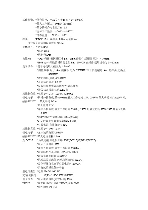
工作参数:*储仓温度:-20℃~+60℃(0~140 oF)*最大工作压力:10Bar(150psi)*最小物料介电常数Σr:2.5*壳体工作温度: -20℃~+60℃*储存温度: -20℃~+85℃探头: *FTC131Z:杆式探头,Φ18mm,最长4m杆式探头最大侧向负载为30Nm壳体型号: *铝壳IP55*铝壳IP66*聚酯壳:IP66电缆塞: *IP55壳体:镍铜质标准Pg, NBR密封件,适用线径为7~10mm.*IP66壳体:聚酰胺材质防水型Pg, N—CR密封件,适用线径为5~12mm.电子插件: *端子连线最大截面为1.5mm2*测量频率:短于4m的探头约为750KHZ,对于长度超过4m的探头,切换至450KHZ.*初始容抗(可调):约400PF*开关延迟量:约0.5秒*高低位报警模式选择开关:旋式开关*开关状态指示.红色LED灯双线制交流*电源U~:21V….250V, 50/60HZ供电电子*瞬时外接负载(最长40ms):最大工作电流1.5A; 250V时最大功耗375V A;24V时, 插件EC20Z 最大功耗36V A.*最大压降:11V*连续外接负载:最大工作电流350Ma; 250V时最大功耗87V A;24V时最大功耗8.4V A*250V时最小负载电流:10Ma(2.5V A)*24V时最小负载电流:20mA(0.5V A)*空载电流(有效值):<5mA三线制直流*电源U~:10V (55V)供电电子*允许波纹电压UPP:5V插件EC22Z *最大电流消耗:15mA及EC23Z *负载连接:集电极开路; PNP(EC22Z)或NPN(EC23Z)*最大开关电压:55V*连续外接负载:最大工作电流350MA*最大峰值冲击电流::1.2A,最长20US*最大负载并联容抗:500NF*抗短路及过载保护:响应阀值约550MA*晶体管开路状态下空载电流:<100UA*具有抗反极性保护功能继电输出型*电源U~:20V~125V交/直流供电或U~:21V~250V,50/60HZ电子插件*最大电流消耗(均方根值):5MAEC24Z *最大峰值冲击电流:200MA,最长5MS*脉冲频率:约1.5S*输出:无源翻转触点器*触点器负载能力:U~最大为250V,I~最大为4AP~最大为1000V A(COSφ=1)或P~最大为350V A,COSφ>=0.7U~最大为100V,I~最大为100W*工作寿命:最大接触负载下,至少可工作十万次*外加翻转延迟:最大1.5S测量系统整个系统是由下列部分组成:1NIVOCOMPACT FTI2电源3用户后接控制系统,开关,信号变送器(如过程控制系统,PLC,继电器,微型触点器,灯,喇叭等).工作原理探头于储仓的侧壁作为两个相对的电极组成一个电容器,而此电容器则被施以一个高频电场.基於放电回路的工作原理而获得具体物位值:当探头位于介电数εR为1的大气中时,放电时间常数τ=R.CA,其中R为电路的阻抗.而CA为探头与器壁所组成电容器的容抗.若具有较高介电常数的物料进入电场区域,则容抗值CA增大,时间常数τ亦随之增大.上述时间长数的变化量被读出,NIVOCOMPACT根据一定的开关工作模式被触发只要物料在探头与仓壁或仓顶之间不行成导通桥路,NIVOCOMPACT就具有很强的抗物料积垢能力.内置的最低/最高位报警模式选择功能保证NIVOCOMPACT所具有很高的操作安全性要求的应用场合以静态电流方式工作.高位报警模式:探头被浸没或电源出现故障时,电路断开.低位报警模式:当探头与被测物料脱离或电源出现故障时,电路断开.位于电子插件上的红色LED显示灯开关状态.应用范围FTC131Z主要用来对小型储仓中细粒散料进行限位探测.FTC331Z用来对大型储仓中细粒或粗粒散料进行限位探测.若储仓中盛放很大颗粒或磨损性很强的物料,NIVOCOMPACTFTC331Z只能用来实现高限位探测.探头之间距离为避免探头之间的相互干扰,不同探头之间应保证至少0.5M的间距位于相邻的由非导电材料组成的储仓中的探头之间亦应保证起码0.5M的距离利用气动式加料机对储仓加料时,探头之间距应更大一些,这样,即使探头晃动,亦能保证其相互间最小间距之要求.储仓加料加料物流应避免直接指向探头.室外安装作为附件供用户选用的全天候保护罩对铝壳结构的Nivocompact开关起到防过热及冷凝之作用.一般而言,大幅度的温度变化极易引起冷凝现象.电气连线(接线)各种不同电子插件的主要特性: 位于产品标牌上的定购代码中的最后一位数字代表位于Nivocompact FTC开关中电子插件的型号:1=电子插件EC20Z双线制交流供电21V (250V)电子开关,最大电流350mA2=电子插件EC22Z三线制直流供电10V (55V)晶体管电路,负载连接PNP,最大电流350mA3=电子插件EC23Z三线制直流供电10V (55V)晶体管电路,负载连接NPN,最大电流350mA4=电子插件EC24Z无源继电输出交流供电21V...250V或直流供电20V (125V)负载极限: 注意与Nivocompact所连负载的极限值超出负载极限会损害或彻底损坏电子插件线径: 工作电流很小,故只需要小线径的电缆建议使用线截面为0.5~1.5mm2的普通电缆接地,与大地等势:必须保证Nivocompact的良好接地性,使其工作可靠,免受外界干扰可将Nivocompact与接地的金属或钢筋型罐壁相连,或将它与大地等势体PE 相连.若在塑料质储仓中已设反极板,则必须在Nivocompact与此反极板之间用一根短线进行接地连接.建立一个等势面势(与大地等势,接地)须严格遵循所有防爆规定.当电子插件安装与Nivocompact中时,自动满足设计认可证书中(A7)1及2所有专门要求/指标.双线制交流供电电子插件EC20Z的连线: 正象所有开关一样,带电子插件EC20Z的物位开关Nivocompact必须与负载(如继电器,微触点器,灯泡等)串接与电源上.在没有任何中介负载情形下,将开关与电源直接相连(短路)会引起迅速而永久的电子插件损坏.负载可串接与电子插件端子1或2的认一端L1亦可与端子1或2的任一端相连.电源电压: 电子插件接线端子1与2之间的端电压值不得低于21V ,电源的端压要稍高于21V,以不偿负载引起的压降.负载开路: 值得注意的是,位报警状态下, Nivocompact的电子插件中的电子开关断路,但此时与之串接的负载并未真正与电源脱开.由于电子插件本身的工作电流要求,此时一个很小的”空载电流”依然流过负载.若负载正好是一只保持电流很小的继电器时,继电器有可能拒绝释放,此时应在继电器两端并接一个负载,如电位器,信号灯等.保险丝: 确保保险丝的功率因子与最大外接负载相匹配.此细径保险丝对电子插件EC20Z不起保护作用三线制直流供电的电子插件EC22Z(PNP)的连线负载受控与晶体管: 接与端子3的负载受控与一只晶体管,类属非接触控制,不会发生返跳现象.正常开关状态下,端子3电位为正物位报警或电源发生故障时,晶体管开路.抗短路保护: 位与端子1与3之间的负载电路具有抗过载及短路能力(脉冲过载保护).过载或短路时,晶体管开路.抗峰压保护: 与强感应仪表相连时,必须接入一只限压器.三线制直流供电的电子插件EC23Z(NPN)的连接负载受控子晶体管电路: 接与端子3的负载受控与一只晶体管,类属非接触控制,故不会发生返跳现象.正常开关状态下,端子3电位为负.物位报警或电源发生故障时,晶体管开路.抗短路保护: 位与端子2和3之间的负载电路具有抗过载及短路的能力(脉冲过载保护) 过载或短路情形下,晶体管开路.抗峰压保护; 与强感应仪表相连时,应接入一只限压器.交/直流供电的电子插件EC24Z的连线电源: 交流供电,L1或N任一端皆可与端子1相连直流供电,L+或L-任一端皆可与端子1相连.服务于负载的继电触点器: 通过一只无源继电触点器(翻转触点器)实现负载的连接,物位报警或电源发生故障时,继电触点器触发,使端子3与4之间短路.抗峰压及短路保护: 在强感应仪表上接入一只火花压制器,用来保护继电触点器.发生短路现象时,细径保险丝F2(功率因子取决于负载大小)可对继电触点器起到保护作用.标定工具准备*齿宽3MM的螺丝刀*齿宽5MM的螺丝刀旋式开关及其他标定过程中所涉调节元件均位于壳体中电子插件上.紧挨标定元件的是电源输入端子,其上电压最大可达250V只允许使用除齿部之外全绝缘的螺丝刀,否则在进行标定之前,必须在电源输入端子上贴上绝缘胶带.容抗标定进行容抗标定时,储仓必须空仓或物位低於探头起码200MM●接通电源●按图23至25的次序进行标定●标定过程中避免水气进入壳体当探头表面被非导电,低介电常数的=固体散料覆盖时,只有当纵向安装探头的一段或横向安装的全部被物料浸没时,NIVOCOMPACT开关才会被触发探头的被覆盖程度取决于於标定工程.反向旋转微标元件,可使NIVOCOMPACT的反应稍许迟钝一些.限位报警模式利用旋式开关,用户可根据实际需要选择合适的限位报警模式*高位报警模式: 探头被物料浸没或电源发生故障时,电流回路开路*低位报警模式:探头裸露於大气中或电源发生故障时,电源回路开路. 功能测试探头裸露於大气中时,用一只带有绝缘柄的螺丝刀接触电子插件的中央紧固螺母,模拟固体散料浸没探头的情形.此时,LED灯的显示状态翻转上述过程仅可用来对仪表的功能控制性能进行测试只有通过现场加料或空仓作业才能真正检查仪表的限位探测功能是否正常.试验过程中物位应:_与侧向安装杆式探头的安装点等高_与纵向安装杆式探头杆端点位置等高_与缆式探头的重锤位置等高!故障排除出现故障时,首先应检查确认*NIVOCOMPACT连接正常*与储仓或反极板接地良好*电源供电正常*所有相连仪表工作正常*使用EC20Z插件时,对相连仪表的最小负载;量要求得到满足*限位报警模式选择正确*标定正确.。
MICRO SWITCH 914CE Series 微型精密限位开关数据手册说明书

MICRO SWITCH Miniature Precision Limit Switches914CE SeriesDESCRIPTIONAll MICRO SWITCH 914CE Series compact enclosed switches incorporate fluorocarbon diaphragm sealing to provide reliable protection, meeting NEMA 1, 2, 3, 3R, 4, 6, 6P, and 13, as well as IP66, IP67, and IP68 requirements. Versions with a boot seal also meet NEMA 12 requirements (dust, falling dirt, liquid media with solid contaminates). The cable or connector and basic switch terminals are encapsulated in an epoxy sealant, offering excellent resistance in harsh environments. For low temperature applications (down to -40 °C, -40 °F), CE Series switches can be supplied with low temperature seals and lubricant.The CE Series switches are rugged and versatile switches which can be applied indoors in many harsh factory floor applications, as well as on outdoor equipment in extreme temperatures. A full range of actuators are available,including plain plungers, roller plungers, side rotary, multi-directional wire, and manually operated. The switches are also available with the industry standard, M12 micro-change 4-pin connector. MICRO SWITCH 914CE products meet North American, cURus standards, as well as European CE requirements.VALUE TO CUSTOMERS• Big performance in a small package• Delivers consistent performance in many demanding environments where petroleum, synthetic, or water based fluids are present• Configurable product platform for design versatilityFEATURES• Rugged, compact construction means minimal real estate on equipment• Die-cast zinc housing and fluorocarbon diaphragm maintain a tightly sealed, NEMA 1, 2, 3, 3R, 4, 6, 6P, 12 (boot seal), 13, and IP66/67/68 package• Pre-leaded (UL cable) or supplied with a M12 four-pin connector• Wide selection of actuators, cable length variations, and side and bottom exit cable/connector options• 25 mm hole-hole mounting footprint engineered with a MICRO SWITCH SM switch for consistent, precise actuation • Well suited for up to 10 million actuation cycles (Up to 5 million actuation cycles for wobble actuators)• Gang mounting capability to provide a multi-plunger limit switch• Low temperature variants available for indoor and outdoor applications• cURus, CE approvals for world-wide usePOTENTIAL APPLICATIONS• Machine tools• Off-road equipment • Material handling• Dock locks and dock levelers • Access and mobility solutions • Textile machinery • Robotics• Packaging equipment • Commercial appliances • Print trade machinery • Agricultural machineryDIFFERENTIATION• Diaphragm seal between the actuator and the switch cavity for high performance sealing• CE series uses MICRO SWITCH SM basic switch for consistent, precise actuationPORTFOLIOHoneywell’s MICRO SWITCH 914CE limit switch is part of a comprehensive offering of rugged and reliable limit switches. To view the entire product portfolio, click here .Sensing and Internet of Things002381Issue 7Table 1. SpecificationsTable 2. Electrical Ratings (in amperes)Model example Contacts Rating914CE* - * Silver contacts A914CE* - *G Gold contacts B914CE* -Q, -AQ, -AQ1, -Q2Silver contactsC with 4 pin connector2 SWITCHING AND LEAD IDENTIFICATION914CErow.BOTTOM EXIT OR SIDE EXIT ORIENTATIONThe CE Series has been designed with a pre-wired cable fittedin the bottom of the switch housing. Other variations are availa-ble with a side exit cable.GOLD CONTACT VERSIONSFor low energy applications (up to 30 Vdc, 1 A), gold contactversions of the 914CE switches can be supplied upon request.Sensing and Internet of Things 34 44 mm max.[1.73 in max.]25 mm [0.98 in]16 mm max.[0.63 in max.]40 mm max.[1.57 in max.]Max. free lengthOperating position (OP) 3 mm min. [0.12 in min.]8,0 mm [0.31 in]8,0 mm [0.32 in]7,6 mm [0.30 in]Pretravel (PT)Overtravel (OT)CABLE VERSIONTYPE Q OE Q2TYPE Q1M12thread1/2 x 20 UNF threadTwo (2) holes Ø 5.1 mm [Ø 0.2 in] dia. c/bore10,2 mm dia x 6 mm deep [0.40 in dia x 0.24 in deep](Both sides - option “A” only)GENERAL DIMENSIONS • ALL SWITCHESPRODUCT NOMENCLATURE914CESwitch Type29Actuator TypeOptions 1914CE Series Small Precision Limit Switch–3Cable LengthConnectorsBottom exit is standard.NOTE: not all combinations of model code are available.Please contact your Honeywell provider/representative for assistance.1More than one option may be permissible.PRODUCT SPECIFICATIONS AND LISTINGSContact your Honeywell rep or distributor for additional listingsSensing and Internet of Things 56 Note: part numbers are shown with 3 ft of cable. The -X indicates the number of feet of cable provided. 6-foot, 9-foot, and 12-foot lengths along with custom lengths, are also available.Sensing and Internet of Things 7Note: part numbers are shown with 3 ft of cable. The -X indicates the number of feet of cable provided. 6-foot, 9-foot, and 12-foot lengths along with custom lengths, are also available.8 m WARNINGPERSONAL INJURYDO NOT USE these products as safety or emergency stop devices or in any other application where failure of the product could result in personal injury.Failure to comply with these instructions could result in death or serious injury.m WARNINGMISUSE OF DOCUMENTATION• The information presented in this product sheet is for reference only. Do not use this document as a product installation guide.•Complete installation, operation, and maintenanceinformation is provided in the instructions supplied with each product.Failure to comply with these instructions could result in death or serious injury.ADDITIONAL MATERIALS• Product installation instructions • Product range guide • Product nomenclature tree• Product application-specific information– Limit and enclosed switches application information – Limit and enclosed switches operating characteristics – Limit and enclosed switches reference standards – Limit and enclosed switches typical applications – Product flyer: CE Family Miniature Limit SwitchesWarranty/RemedyHoneywell warrants goods of its manufacture as being free of defective materials and faulty workmanship during the appli-cable warranty period. Honeywell’s standard product warranty applies unless agreed to otherwise by Honeywell in writing; please refer to your order acknowledgment or consult your local sales office for specific warranty details. If warrantedgoods are returned to Honeywell during the period of coverage, Honeywell will repair or replace, at its option, without charge those items that Honeywell, in its sole discretion, finds defec-tive. The foregoing is buyer’s sole remedy and is in lieu of all other warranties, expressed or implied, including those of merchantability and fitness for a particular purpose. In no event shall Honeywell be liable for consequential, special, or indirect damages.While Honeywell may provide application assistance personally, through our literature and the Honeywell web site, it is buyer’s sole responsibility to determine the suitability of the product in the application.Specifications may change without notice. The information we supply is believed to be accurate and reliable as of this writing. However, Honeywell assumes no responsibility for its use.Viton ® is a registered trademark of DuPont Performance Elastomers L.L.C.002381-7-EN | 7 | 06/18© 2018 Honeywell International Inc. All rights reserved.For more informationHoneywell Sensing and Internet of Things services its customers through a worldwide network of sales offices and distributors. For application assistance, current specifications, pricing or the nearest Authorized Distributor, visit or call:Asia Pacific +65 6355-2828Europe +44 (0) 1698 481481USA/Canada+1-800-537-6945Honeywell Sensing and Internet of Things 9680 Old Bailes Road Fort Mill, SC 29707 www. 。
Eaton LS-Titan限位开关TD05208001E设备说明说明书

New output options with LS-Titan limit switchesLSE-AX switch body IntroductionHistorically, limit switches were electromechanical devices providing a simple “open” or “closed” output. With the introduction of LS-Titan E, Eaton introduces new output options for limit switches: analog and solid-state outputs.Analog output limit switches (LSE-AX)Traditional limit switches are either “open” or “closed,” and as such, the user is provided with only two pieces of information. The LS-Titan limit switch family features a third output option: analog. Available in either 0–10 Vdc or 4–20 mA current loop signals, analog outputs are proportional to the position of the actuator within the limit switch body.Figure 1. Analog OutputThe graph above shows the analog output as it changes proportionally to the position of the switch actuator.Eaton Corporation Electrical Sector1111 Superior Ave. Cleveland, OH 44114United States877-ETN-CARE (877-386-2273) © 2010 Eaton CorporationAll Rights ReservedPrinted in USAPublication No. TD05208001E / Z9642 March 2010PowerChain Management is a registered trademark of Eaton Corporation.All other trademarks are property of their respective owners.Technical Data TD05208001E Effective March 2010New output options with LS-Titan limit switchesThe widespread use of inexpensive programmable logic controllers with analog inputs makes it easy to obtain far more application information than ever before.Now it is possible to answer a wide range of application questions:• Just how close is the target, in real-time?• How quickly is the target moving?• Is the target in the acceptable position range?• Should the machine speed up or slow down to compensate?LS-XRLAAnalog switch application exampleIn a typical application, an operator may want to monitor the position of ventilation in a damper door. The damper door can either be controlled by a linear motor or a manual override. In automatic mode, the linear motor is equipped with a feedback signal that communicates the door position back to the system, but whenin manual mode, the system still needs to know the door location. The basic analog output switch body is equipped with a small plunger providing just a few millimeters of vertical travel. While it would be possible to use the switch body by itself, it would be even easier to apply the switch with the switch head model LS-XRLA, featuring an adjustable length roller lever. Now, instead of just a few millimeters of motion, the switch lever can be adjusted to over 75 millimeters long and can be rotated to over 60 degrees either clockwise or counterclockwise.To install, position the switch relative to the door such that as the door moves through its travel, the lever makes the largest change in degrees possible up to the maximum of 60. The analog output of the switch is broken into 100 steps, so it is preferred to useas much of the switch’s range as possible to provide the highest resolution. This will result in the smoothest output curve possible.Solid-state output limit switches(LSE-02 and LSE-11)The LS-Titan family also offers two switch bodies with solid-state outputs. Typically found in optical or inductive switches, solid-state provides a number of advantages over mechanical contacts—and some disadvantages as well. Understanding the differences between these device types is critical to correctly applyingthe switch.Solid-state switches provide four key advantages over typical mechanical devices: adjustable trip points, lack of “contact bounce,” the ability to switch very low currents, and betterlong-term reliability.Traditional limit switches require the user to determine the trip point through a process of trial and error, or by providing some external mechanical adjustment. The solid-state switches in the LS-Titan family provide a “learn button” that allows the user to set the trip point. This makes installation and setup much quicker than the traditional method.When mechanical switches are applied to certain applications—like a switch feeding into a high-speed counter—problems can arise due to “contact bounce,” defined as an intermittent and usually undesirable opening of mechanical contacts during closure. This phenomenon could result in a single switch actuation being counted multiple times, resulting in inaccurate data to the counter. Solid- state devices do not have the contact bounce characteristic— these switches are either open or closed during a single event. Solid-state devices are also able to switch very low currents. Mechanical switches can sometimes develop contact resistance that can inhibit the ability to switch low currents over time.Some manufacturers have designed gold-flashed or self-wiping mechanical contacts to reduce the chances of contact resistance building up over time.Since solid-state switches don’t feature a mechanical operation, they are also more reliable over long time periods. Contact wear, caused by arcing during the switching of inductive loads, is not a problem with a solid-state device.Solid-state switches are not perfect for every application. Most are not rated for switching high currents, and are limited to DC-only operation. But, in the right application, solid-state switches canprovide significant advantages over their mechanical counterparts.。
施迈赛

施迈赛现货SCHMERSAL安全门开关专业代理SCHMERSAL施迈赛AZ15ZVK-M16热价销售中SCHMERSAL施迈赛上海AZ15ZVRK-M16现货SCHMERSAL施迈赛AZ15ZVK-1476-1热价SCHMERSAL施迈赛AZ15ZVRK-1476-1好价格SCHMERSAL上海大量供应AZ15ZVK-1476-1/1762SCHMERSAL上海大量供应AZ15ZVK-M16-1762SCHMERSAL上海大量供应AZ15ZVRK-M16-1762SCHMERSAL上海大量供应AZ15ZVRK-M16-2254SCHMERSAL施迈赛AZ16-02ZVK-M16上海热价SCHMERSAL施迈赛AZ16-02ZVRK-M16供应现货SCHMERSAL施迈赛现货AZ16ZVRK-M16热卖SCHMERSAL AZ16ZVRK-M16-1476-1现货热价促销施迈赛上海AZ16-12ZVRK-M16好价格SCHMERSAL施迈赛现货AZ16-12ZVRK-M16-1476-1SCHMERSAL上海 AZM161SK-12/12RK-024现货销售SCHMERSAL上海供应AZM161SK-12/12RK-110/230 SCHMERSAL现货热价销售AZM161SK-24RK-024SCHMERSAL上海AZM161SK-33RK-024现货热价供应SCHMERSAL上海供应AZM161SK-33RK-024 M16 SCHMERSAL现货热价销售AZM161-B1SCHMERSAL上海AZM161-B6热价销售中SCHMERSAL现货热价销售AZM170-02ZRK 24VDC/AC SCHMERSAL上海现货供应AZM170-11ZRKA 24VDC/AC SCHMERSAL上海供应AZM170SK-02/10ZRK-2197 24VAC/DC SCHMERSAL上海供应AZM170SK-02ZRK-2197 24VAC/DC SCHMERSAL上海供应AZM170SK-12/00ZK-2197 24VAC/DCSCHMERSAL插销供应SCHMERSAL上海大量供应AZ15/16-B1 SCHMERSAL上海大量供应AZ15/16-B2 SCHMERSAL上海大量供应AZ15/16-B3 SCHMERSAL施迈赛插销AZ15/16-B6现货供应SCHMERSAL上海大量供应AZ15/16-B1-2245 SCHMERSAL上海大量供应AZ17/170-B1 SCHMERSAL上海大量供应AZ17/170-B5 SCHMERSAL上海大量供应AZ17-B6 SCHMERSAL上海大量供应AZ17-B1-2245235限位开关系列SCHMERSAL上海ZV7H235-11Z-M20热销SCHMERSAL现货供应TV12H235-11Z-M20236限位开关系列施迈赛ZR236-11Z-M20上海热销施迈赛ZR236-11Z-M20-RMS上海大量现货施迈赛ZV7H236-11Z-M20上海大量库存施迈赛ZV1H236-11Z-M20比卓好价格施迈赛ZR236-11Z-M20-1894上海好价格SCHMERSAL上海供应T1R236-02Z-H-U180-1458 SCHMERSAL上海供应T1R236-11Z-UE-U180-2127 SCHMERSAL上海供应Z1R236-11zr-U180-2126 SCHMERSAL上海供应Z1R236-11ZR-2126SCHMERSAL 336限位开关系列施迈赛SCHMERSAL Z4V7H336-11Z-2272/2654施迈赛SCHMERSAL Z4VH336-11Z-M20施迈赛SCHMERSAL T4VH336-20Z施迈赛SCHMERSAL T4VH336-02Z施迈赛SCHMERSAL T4V10H336-11Z-M20施迈赛SCHMERSAL Z4V10H336-11Z施迈赛SCHMERSAL ZS336-11Z-M20施迈赛SCHMERSAL ZR336-11Z-M20335限位开关SCHMERSAL 335限位开关系列SCHMERSAL施迈赛Z4VH335-11Z-RV A热价SCHMERSAL施迈赛Z4V7H335-11Z-M20现货供应SCHMERSAL施迈赛Z4V7H335-11Z-2272/2654大量现货SCHMERSAL施迈赛Z4VH335-11Z-M20上海热销SCHMERSAL施迈赛Z4V7H335-11Z-RVA-2272/2654好价格SCHMERSAL施迈赛ZV14H235-11Z-M20热价销售中SCHMERSAL施迈赛ZS335-11Z-M20热销中SCHMERSAL施迈赛ZR335-11Z-M20现货促销SCHMERSAL施迈赛Z1K335-11Z-M20热价出售SCHMERSAL重型限位开关热价促销SCHMERSAL现货大量供应MK441-11YSCHMERSAL T.441-11Y-UE-966现货大量供应SCHMERSAL TD422-01Y-2512-10现货热销SCHMERSAL现货MV7H330-11Y供应SCHMERSAL上海供应MV7H330-11Y-M20SCHMERSAL上海供应MV8H330-11Y-M20SCHMERSAL现货大量供应TA064-12Y-2512-2SCHMERSAL现货TD441-11Y-2512-10供应SCHMERSAL施迈赛现货ML441-11Y-T-2512-6热销施迈赛ML441-11Y-2512-6现货热销施迈赛ML441-11Y-2512-16上海热价施迈赛T.441-11Y-UE-243好价格施迈赛MD441-11Y-2512-10热价出售安全继电器SCHMERSAL上海大量库存现货供应SRB301LCSCHMERSAL上海供应SRB301ST 24VAC/DC上海大量库存现货供应SCHMERSAL上海供应SRB201 ZH 24VDCSCHMERSAL上海供应SRB301 LC 24VAC/DCSCHMERSAL上海供应SRB301 LC/B24VSCHMERSAL上海供应SRB301MCSCHMERSAL上海供应SRB-C.46-SNA-24VSCHMERSAL上海供应SRB301LCI,24VAC/DCSCHMERSAL上海供应SRB301SQ,230VSCHMERSAL上海供应SRB301ST,230VSCHMERSAL上海供应SRB301ST,V.2,24VAC/DC SCHMERSAL上海供应SRB301X1SCHMERSAL上海供应SRB302X3脚踏开关Steute斯陶特ZF232-11上海热卖Steute斯陶特上海ZS232-11好价格Steute斯陶特上海大量库存供应TFH232-11Steute斯陶特KF 1PW 2M现货Steute斯陶特上海现货KF 1S 2M接近开关SCHMERSAL上海大量库存现货供应IFL15-30-10T SCHMERSAL上海IFL50-385-10/01大量库存现货供应拉线开关Steute斯陶特上海ZQ900-22现货供应Steute斯陶特上海大量库存ZQ900-22NSteute斯陶特现货ZQ700-11Steute斯陶特上海现货销售ES51Z10/1SSteute斯陶特ES41Z 10/1S热价Steute斯陶特现货供应ZS7310/1SWVD 195NSteute斯陶特ZS7310/1S VD上海热销Steute斯陶特上海ZS75S-20/2S VD好价格Steute斯陶特ZS7110/1S VD现货热销Steute斯陶特上海大量库存ZS73S10/1SVDSteute斯陶特上海现货ZS7120VDSteute斯陶特ZS7510/1SVD施迈赛产品AZ17系列安全门锁开关SCHMERSAL施迈赛上海供应AZ17-11zk SCHMERSAL施迈赛上海供应AZ17-11zrk SCHMERSAL施迈赛上海供应AZ17-02zk SCHMERSAL施迈赛上海供应AZ17-02zrk安全门锁开关SCHMERSAL施迈赛上海供应AZM190-11/01RK24VDC SCHMERSAL施迈赛上海供应AZ335-11ZK SCHMERSAL施迈赛上海供应AZ335-11ZUKSCHMERSAL施迈赛上海供应AZ335-02ZK SCHMERSAL施迈赛上海供应AZM415-22ZPKA SCHMERSAL施迈赛上海供应AZM415-22ZPKNS SCHMERSAL施迈赛上海供应AZ335-B1 SCHMERSAL施迈赛上海供应AZM190-B1 SCHMERSAL施迈赛上海供应AZ/AZM415-B1 SCHMERSAL施迈赛上海供应AZ/AZM415-B2行程开关SCHMERSAL上海供应TR256-11Z-M20SCHMERSAL上海供应TZFCW/96SCHMERSAL上海供应TZF-SNA24VDCSCHMERSAL上海供应TZFS-SNASCHMERSAL上海供应ZK4236-11ZR-U180-1816SCHMERSAL上海供应TZM/96/M20M(S1)系列负重荷行程开关,行程开关ML441-11Y,行程开关MD441-11Y,行程开关MK441-11Y,行程开关MJ441-11Y,行程开关MS441-11Y,,行程开关MR441-11Y,行程开关M2C441-11Y,行程开关M.441-11Y-243安全磁开关SCHMERSAL上海供应BNS333-01Y-M20 SCHMERSAL上海供应BNS250-11ZG SCHMERSAL上海供应BNS303-12ZG SCHMERSAL上海供应BNS33-02ZG SCHMERSAL上海供应BNS120-11Z SCHMERSAL上海供应BNS180-11ZS SCHMERSAL上海供应BNS33-11Z SCHMERSAL上海供应BNS33-11ZG-STSCHMERSAL上海供应BN20-11RZ SCHMERSAL上海供应BN20-10Z-M16 SCHMERSAL上海供应BN20-11Z-M16SCHMERSAL上海供应BN20-20ZSCHMERSAL上海供应BN20-2RZ-M16SCHMERSAL上海供应BN20-RZ-M16SCHMERSAL上海供应BNS250-11Z-3M SCHMERSAL上海供应BN20-11RZ-M16 SCHMERSAL上海供应BN20-11Z-M16 SCHMERSAL上海供应BN310-01Z SCHMERSAL上海供应BN310-RZ-2503 SCHMERSAL上海供应BN31-RZ SCHMERSAL上海供应BN32-11 SCHMERSAL上海供应BN325-R SCHMERSAL上海供应BN32-R-1239 SCHMERSAL上海供应BN65 RZ/V SCHMERSAL上海供应BN85-RE SCHMERSAL上海供应BNS120-12Z SCHMERSAL上海供应BNS250-11Z SCHMERSAL上海供应BNS250-12Z-2187 SCHMERSAL上海供应BNS300-01ZG 50M磁铁供应:SCHMERSAL,BP10SCHMERSAL,BP12NSCHMERSAL,BP15SCHMERSAL,BP15/2SCHMERSAL,BP20SCHMERSAL,BP20NSCHMERSAL,BP20SSCHMERSAL,BP21NSCHMERSAL,BP21SSCHMERSAL,BP22N(S)SCHMERSAL,BP31NSCHMERSAL,BP31SSCHMERSAL,BP34SCHMERSAL,BPS250SCHMERSAL,BPS33SCHMERSAL,BPS250SCHMERSAL,BPS300SCHMERSAL,BPS303SCHMERSAL,BPS303SS安全边沿开关SE40SE70铝支架施迈赛安全边沿开关SE-AL10-1250SE-AL10-2500上海好价格SE-AL12-1250上海大量库存现货SE-AL12-2500上海热卖SE-AL20-1250施迈赛德国施迈赛SE-AL20-2500上海供应上海出售SE-AL22-1250SE-AL22-2500现货供应橡皮支架SE-P40-1250上海地区代理施迈赛SCHMERSAL SE-P40-2500有货SE-P40-5000上海比卓好价格施迈赛SCHMERSAL SE-P40-10000上海供应施迈赛SCHMERSAL SE-P70-1250热价SE-P70-2500上海地区代理SE-P70-5000上海地区代理SE-P70-10000上海热销安全控制模块SCHMERSAL上海供应AES1135 SCHMERSAL上海供应AES1235 SCHMERSAL上海供应AZR31R2 24VDC SCHMERSAL上海供应AZR31R2 230VAC SCHMERSAL上海供应AZS2305 24VDC SCHMERSAL AES2135上海比卓SCHMERSAL德国施迈赛SE-100C上海供应SCHMERSAL施迈赛AZR11RT2上海热销SCHMERSAL上海供应AZR11RT2 SCHMERSAL AZR31R2/110VAC SCHMERSAL AZR31S1/24VDC SCHMERSAL AZR31T0/24VDC/AC SCHMERSAL AZR31T2/24VAC SCHMERSAL AZR31T2/24VDC光电开关SCHMERSAL施迈赛SLB200-E31-21 SCHMERSAL施迈赛SLB200-R31-21 SCHMERSAL施迈赛SLB400-E50-21P SCHMERSAL施迈赛SLB400-R50-21P SCHMERSAL施迈赛SLB200-C04-1R SCHMERSAL施迈赛SMA366LSS300-1110安全地毯开关SCHMERSAL施迈赛SMS3100X100 SCHMERSAL上海供应SMS350X100 SCHMERSAL安全地毯开关SMS3250X500 SCHMERSAL施迈赛SMS350X50 SCHMERSAL上海热销SMS375X100 SCHMERSAL施迈赛SMS3100X150Z/T336系列开关施迈赛ZR336-02Z上海热销施迈赛上海供应TR336-11Z施迈赛TR336-11ZU上海比卓施迈赛TR336-20Z上海一级代理商比卓自动化TR336-20ZH好价格德国施迈赛TR336-02Z施迈赛TR336-02ZH上海热销施迈赛上海供应TR336-11Z施迈赛TR336-11ZU上海比卓施迈赛TR336-20Z上海一级代理商比卓自动化TR336-20ZH好价格德国施迈赛TR336-02Z施迈赛TR336-02ZH上海热销Z/T335标准限位开关上海供应ZVH335-02ZT4VH335-11Z热销德国施迈赛T4VH335-11ZU施迈赛T4VH335-20Z上海一级代理SCHMERSAL施迈赛T4VH335-20ZH施迈赛T4VH335-02ZT4VH335-02ZHSCHMERSAL上海供应T3K33511Z SCHMERSAL施迈赛T3K335-11ZU德国施迈赛ZS335-02Z上海一级代理施迈赛TS335-11Z热销施迈赛TS335-11ZU上海比卓好价格TS335-20Z施迈赛TS335-20ZH上海热销施迈赛TS335-02Z热销德国施迈赛TS335-02ZH上海一级代理施迈赛Z3K335-11Z上海销售SCHMERSAL上海供应Z3K335-02Z德国施迈赛T3K335-11Z上海供应SCHMERSAL施迈赛T3K335-11ZUT3K335-20Z热价出售T3K335-20ZH热销SCHMERSAL施迈赛T3K335-02Z SCHMERSAL上海热销T3K335-02ZHM330系列限位开关德国施迈赛MS330-11YMS330-11Y-1366上海热销SCHMERSAL上海供应MS330-11Y-M20-1366 S0系列限位开关TS015-11Y热销MS015-11Y热价出售S1系列限位开关上海供应TS422-10Y德国施迈赛TK441-11YTD442-10Y上海比卓好价格跑偏开关MV10H330-11Y-1348上海一级代理施迈赛T.441-11Y-14上海热销德国施迈赛M.441-11Y-14T.441-11Y-243上海热价出售Z/T256系列限位开关,限位开关ZR256-11Z,限位开关Z4R256-11Z,限位开关ZS256-11Z,限位开关Z4S256-11Z,限位开关ZK256-11Z,限位开关ZK4256-11Z,限位开关ZV7H256-11Z,限位开关Z3K256-11Z,限位开关ZV10H256-11Z,限位开关ZV1H256-02Z,, 限位开关Z4K256-02Z,限位开关ZR256-02Z,限位开关Z4R256-02Z,限位开关ZS256-02Z,限位开关Z4S256-02Z,,限位开关ZK256-02Z,限位开关ZK4256-02Z,限位开关ZV7H256-02Z,限位开关Z3K256-02Z,限位开关ZV10H256-02Z,,限位开关ZV1H256-02Z,限位开关Z4K256-02Z,限位开关TR256-11Z,限位开关T4R256-11Z,限位开关TS256-11Z,,限位开关T4S256-11Z,限位开关T4K256-02Z,限位开关TK4256-11Z,限位开关TV7H256-11Z,,限位开关Z3K256-11Z,限位开关TV10H256-11Z,限位开关TV1H256-11Z,限位开关T4K256-11Z,限位开关TR256-02Z,,限位开关T4R256-02Z,限位开关TS256-02Z,限位开关T4S256-02Z,限位开关TK256-02Z,限位开关TK4256-02Z,,限位开关TV7H256-02Z,限位开关T3K256-02Z,限位开关TV10H256-02Z,限位开关TV1H265-02Z, 限位开关TK256-11Z限位开关德国施迈赛TS064-21Y施迈赛TS064-12Y上海供应上海供应TS064-22Y上海热卖TS064-31Y上海一级代理商TA064-21Y施迈赛TA064-20/10Y热销上海热销TA064-10/20Y施迈赛TL064-21Y上海比卓好价格TL064-12Y上海供应施迈赛MS064-21Y上海比卓代理MS064-12YMA064-21Y热价施迈赛MA064-12Y热销MA064-30Y上海热销MA064-22Y上海比卓施迈赛T2A067-11Y热销T2A067-10/10Y上海热价上海TA471-20/20Y热销施迈赛TA471-12/12YTA471-03/03Y上海热卖德国施迈赛MA471-21Y热销MA471-12Y上海热卖Steute斯陶特脚踏开关Steute斯陶特KF1SD1S上海供应Steute斯陶特KF1SPNP上海供应Steute斯陶特KF1SNPN上海供应Steute斯陶特KF2系列上海供应KF1S2MTULLESteute斯陶特KF31PW/1PW/1PWSteute斯陶特KF41PW/1PW/1PW/1PWSteute斯陶特GFM10/1S上海供应Steute斯陶特GF10/1S上海供应Steute斯陶特GFM20/2S上海供应Steute斯陶特GF20/2S上海供应Steute斯陶特GFSM10/1S上海比卓Steute斯陶特GFS10/1S上海好价格Steute斯陶特GFSM20/2S上海供应Steute斯陶特GFS20/2S上海供应斯陶特脚踏开关GFSMK10/1S上海供应(带踏板罩)斯陶特GFSK10/1S上海供应(带踏板罩)斯陶特GFSNA上海供应斯陶特GFHS上海供应Steute GFP0TI上海比卓出售Steute GFSP0TI上海大量库存斯陶特GFM210S/10S双踏板斯陶特GF210S/10S双踏板斯陶特GFM220S/20S双踏板斯陶特G F220S/20S双踏板GFM310S/10S/10S三踏板斯陶特防爆开关Steute GFSIM10/1S上海一级代理商(防爆)Steute GFSI10/1S(防爆)Steute GFSIM20/2S(防爆)Steute GFSI20/2S(防爆)斯陶特拉线开关上海一级代理Steute斯陶特上海EM41Z10/1SSteute斯陶特上海ES41Z2SSteute斯陶特上海ES61Z10/1SSteute斯陶特上海EM61Z10/1SSteute斯陶特上海ZS7320Steute斯陶特上海ZS7520/2SSteute斯陶特上海ZS8020/2SSteute斯陶特上海ZS8030/1SSteute斯陶特上海ZS70Z10/1SSteute斯陶特上海ZS73S20Steute斯陶特上海ZS75S10/1SSteute斯陶特上海ZS75S20/2S SCHMERSAL上海供应ES51Z10E/1S SCHMERSAL上海供应ES51Z10E/1S-80N斯陶特TQ700-11拉绳开关斯陶特ZQ700-02斯陶特ZQ900-11拉绳开关斯陶特ZQ900-13现货斯陶特ZQ900-02斯陶特ZQ900-22拉绳开关斯陶特ZQ900-04现货斯陶特ZQ900-02N斯陶特ZQ900-13N拉绳开关斯陶特ZQ900-04N现货斯陶特STEUTE常用型号斯陶特上海供应EEXZS75SR10/1SEEx3551K-10/1S斯陶特上海热卖上海热销斯陶特EEx3551K-20EEx3551K-1S/10UE(steute世德)steute世德上海大量供应EEx3553K-10/1S steute世德EEx3553K-20steute世德EEx3553K-1S/10UEsteute世德EEx3554VH-10/1Ssteute世德上海大量供应EEx3554VH-20 EEx3354VH-1S/10UE(steute世德)上海热销EEX3554V3H10/1SEEXT3564V10H10/1S 2M热卖上海供应EEX335R10/1SEEX13TK10/1S 5M上海热卖斯陶特EEXT3564V10H10/1S 5M上海EEXT3564V7H10/1S 2MEEXT3564V10H10/1S 5M现货销售EEXT3564V7H10/1S 2M现货销售SCHMERSAL施迈赛ZS75-2U-D SCHMERSAL施迈赛EEXT4VH356-11Z SCHMERSAL施迈赛EEXT4V7H356-11Z SCHMERSAL施迈赛EEXT4V10H356-11Z SCHMERSAL施迈赛EEXTR356-11Z SCHMERSAL施迈赛EEXTS3569-11Z SCHMERSAL施迈赛MSP452-11/11Y-M20 SCHMERSAL施迈赛M3R-330-11YU通用控制开关SCHMERSAL施迈赛HLU110-2施迈赛HLU110-10施迈赛HLU110-5KT施迈赛HLU110-1KT施迈赛HLU110-7KT施迈赛HLU110-2T施迈赛HLU110-1KTHLU110-9HLU110-5KTHLU142VAC Ith6AHLU110-5KT施迈赛接近开关施迈赛SCHMERSAL上海大量供应IFL2-12-10施迈赛SCHMERSAL上海大量供应IFL4-12-01施迈赛SCHMERSAL上海大量供应IFL4B-12-01T施迈赛SCHMERSAL上海大量供应IFL5-18-01施迈赛SCHMERSAL上海大量供应IFL8-18-10ST施迈赛SCHMERSAL上海大量供应IFL10-180-10施迈赛SCHMERSAL上海大量供应IFL20-400-01T 施迈赛SCHMERSAL上海大量供应IFL15-333E-01 施迈赛SCHMERSAL上海大量供应IFL20-333E-10 施迈赛SCHMERSAL上海大量供应IFL15-333-10/01 施迈赛SCHMERSAL上海大量供应IFL20-333-10/01 施迈赛SCHMERSAL上海大量供应IFL30-384-10-01 施迈赛SCHMERSAL上海大量供应IFL15-30-10/10 施迈赛SCHMERSA上海大量供应IFL8-180L-10P SCHMERSAL上海供应IFL15-30-10STPSCHMERSAL上海供应IFL4-12M-01P 5M SCHMERSAL上海供应IFL4-12M-10P 5M SCHMERSAL上海供应IFL50-385-10/01-M20SCHMERSAL上海供应IFL5-18-10A施迈赛转速监视器DIM1.1230VAC。
MICRO SWITCH LSX系列有害区限位开关数据手册说明书

LSXYAB4L LSXP3K LSXP3K LSXYAB4LMICRO SWITCH™ Hazardous Area Switches Datasheet2What makes our switches better?Industry-leading breadth of productWeather sealed to NEMA 1, 3, 4, 6, 13Explosion proof to NEMA 7 (Class 1, Division 1 & 2, Groups B, C, D), NEMA 9 (Class 2, Division 1 & 2, Groups E, F , G) Extensive variety of actuation heads and multiple non-sparkingactuators All metal drive train that offers consistent operating characteristicsthrough a broad temperature range. Also lasts longer (without need for frequent adjustment) than drive trains with plastic partsMICRO SWITCH™ LSX Series Hazardous Area Limit SwitchesMICRO SWITCH™ LSX hazardous area switches are designed for use in adverse environments. They are approved for use in hazardous locations and NEMA classified atmospheres because their rugged housings have integral flame paths. These flame paths force internal expanding gases to cool below external atmosphere ignition temperatures before they leave the housing. The LSX also features tracking interchangeability with MICRO SWITCH™ BX Series Hazardous Area switches. An optional mounting plate provides the same tracking and mounting as the standard HDLS Series (heavy-duty limit switch).The majority of HDLS operating heads and circuitry options are available for the LSX Series. The rotary actuated LSX series products are designed for use with levers that have non-sparking actuators due to the potentially hazardous environment. The other styles of LSX Series switches which are the plunger actuated and wobble actuated products incorporate an integral non-sparking actuator.SAFE • RELIABLEEXPLOSION PROOF • WEATHER SEALEDFeatures and Benefits DESIGN FLEXIBILITYMICRO SWITCH™ LSX limit switches’ field adjustability (CW-CCW operation, rotatable operating head) assists in matching the switch to the application. Available with momentary, maintained, sequential, or center neutral action.UNIQUE DESIGN FEATURESThe head design is keyed for more secure head-to-body retention with the head indexable in any one of four positions 90° apart. Captive mounting screws in the heads help prevent the loss of screws during replacement or repositioning of the head. Self-lifting pressure plate terminals save wiring time.WITHSTANDS MANY CAUSTIC ENVIRONMENTSA die-cast zinc head and aluminum body make the LSX suitable for indoor and outdoor applications. A diaphragm seal between the head and body is designed to provide an extra measure of protection. Switches remain functional when exposed to many severe environments and caustic chemicals.OPTIONAL SEALSStandard seals are suitable for most applications, but optional fluorocarbonor fluorosilicone seals are available for many harsh chemical, high or low temperature environments.DESIGNED TO CONTROL LOW-VOLTAGE DC APPLICATIONS Hazardous area switches are available with a choice of silver or gold-plated contacts to handle a variety of electrical load requirements from low energy to power-duty control.Industry-leading breadth of productsAll-metal drive train for consistent operation34GRAIN ELEVATORSMonitors plugged grain conveyors, slide gate position, diverter valves, and leg positionsCONTROL VALVES AND ACTUATORSSenses the “on” or “off” position of the valveON-SHORE DRILLINGDetects end of travel positions for extend and retract operations of drilling equipmentPIPELINESMonitors pig position and resulting pipeline healthPETROCHEMICAL AND CHEMICAL PLANTSMonitors the position of control valves, doors, and gatesWATER TREATMENT PLANTSDetects control valve positionPAINT BOOTHSDoor interlocks for sliding or hinged gates or doorsHAZARDOUS WASTE HANDLINGOften used as a valve position monitorPotential Applications5MICRO SWITCH™ Hazardous Area Limit SwitchesFigure 1. MICRO SWITCH™ LSX SERIES FEATURES AND OPTIONS0.5 in or 0.75 in conduit optionsSintered, bronze bearings enable longer operating life and increase resistance in corrosive environments Dual bearings deliver enhanced mechanical lifeTwin shaft seals for improved environmental protection. Optional fluorosilicone seals extend operating temperaturedown to -40 °C [-40°F]Two flame paths:one in the cover-housing threads; another between the switch cavity and headBoss-and-sockethead design for more secure head-to-body retentionField adjustabilityof operating head matches switch to applicationRugged zinc head and aluminum body are phosphate treated and epoxy coatedLSX Series LSXSwitch Type LSX Series HazardousAreaSwitch Head StyleJ7AActuatorOptions3KCircuitry andConduit ConnectionModificationCode–Not all combinations available. Please contact Honeywell for assistance.To order high temperature versions, insert the additional letters Y and C in the appropriate places in the standard catalog listing, as shown below:LSXA3K standard, side-rotary plug-in switchLSXYAC3K completely FC-sealed version of LSXA3KTo order low temperature versions, insert the additional letters Y and B in the appropriate places in the standard catalog listing, as shown below:LSXA3K standard, side-rotary plug-in switchLSXYAB3K low-temperature version of LSXA3KFor more details, please see page 8.Figure 2. MICRO SWITCH™ LSX SERIES NOMENCLATUREMICRO SWITCH™ Hazardous Area Limit Switches* Reference operating head styles on page 9 and 10 for exceptions.78LSX Series* For LSX application wherein the upper temperature limit is normally above 93 °C [200 °F], extended switch life can be obtained by using completely fluorocarbon-sealed switches rather than standard LSX.MICRO SWITCH™ LSX SERIES ELECTRICAL RATINGS: 10 A CONTINUOUS CARRYac VOLTS; PILOT DUTY: AC15, A600MICRO SWITCH™ LSX SERIES ELECTRICALRATINGS: dc VOLTS; PILOT DUTY: DC13, R300MICRO SWITCH™ LSX limit switches are capable of the followinglow voltage dc loadsSWITCH CONTACT STYLES, DOUBLE BREAKNOTE: Same polarity each pole9MICRO SWITCH™ Hazardous Area Limit SwitchesMICRO SWITCH™ LSX SERIES OPERATING HEADSSIDE ROTARY: Heads may be positioned in any one of four posi-tions, 90° increments. All are momentary action except maintainedhead (LSXN Series).LSXA - Standard: 60° minimum over-travel, 15° maximum pretravel,5° (single pole) and 7° (double pole) maxi-mum differential travel.LSXR - Low operating torque: 60° minimum overtravel, 15° maximum pretravel, 0.19 Nm [1.7 in-lb] maximum operating torque.LSXN - Maintained contact: Maintained on counterclockwise rotation and reset on clockwise rotation, and vice versa. LSXP - Low differential: 68° minimum overtravel, 9° maximum pretravel, 3° (single pole) and 4° (double pole) maximum differen-tial travel.LSXH - Low torque, low differential travel: 68° minimum overtravel. Features low operating torque and narrow differential travel.LSXL - Sequence action: 48° minimum overtravel. Delayed action between operation of two poles.LSXM - Center neutral: 57° minimum overtravel. One pole operates on the clockwise rotation, and the other pole on the counterclockwise rotation.LSXU - Low pretravel: 5° max. pretravel, 70° min. overtravel.TOP ROTARY: Available levers provide greater versatility. Heads may be positioned in any one of four positions, 90° increments. Allare momentary action.LSXB: With 100° minimum overtravel.Various levers that fit side rotary shafts may be used on the top rotary shaft. Switch is suitable for use when increased overtravel is required.HIGH TEMPERATURE/CHEMICAL RESISTANT SWITCHESCompletely fluorocarbon (FC)-sealed switches have a full FC body gasket covering the switch cavity. Rotary types have an extra FC seal on the operating shaft, while plunger versions have FC boot seals. They are designed for use in applications where the environment includes fire-resistant synthetic fluids. In addition, the FC-sealed switches may be used with such industrial fluids as Cellulube, Fyrquell, Houghto-Safe, Pydraul, and other special cutting and hydraulic fluids. The additional FC seals also promote extended operating life for rotary-actuated LSX switches in applica-tions where the temperatures are normally -12 °C to 121 °C [10 °F to 250 °F].To order, insert the additional letters Y and C in the appropriate places in the standard catalog listing, as shown below:LSXA3K standard, side-rotary plug-in switch LSXYAC3Kcompletely FC-sealed version of LSXA3KLOW TEMPERATURE SWITCHESAll forms of LSX limit switches are also available in low-temperature construction. Design features include fluorosilicone diaphragm, shaft seals, and external boot seal (where applicable).To order, insert the additional letters Y and B in the appropriate places in the standard catalog listing, as shown below:LSXA3K standard, side-rotary plug-in switch LSXYAB3Klow-temperature version of LSXA3KSPECIAL OPTIONSTOP PLUNGERS: Available with 4,83 mm [0.19 in] minimum overtravel. Top pin plungers are offered in pin plunger, anadjustable plunger, and a roller plunger.LSXC - Top pin plunger: A copper alloy plunger for in-line actuating motion. Oil-tight seals on plunger and between the operating head and housing are designed to keep out coolant, dust, and chips.Momentary action.LSXD - Top roller plunger: A copper alloy roller plunger is adjustable to 90° angles to accept cam or slide operation from any of two directions. Boot seal onthe plunger. Momentary action.LSXV - Adjustable top pin plunger: A copper alloy adjustable plunger is designed to simplify the application and decreases installation time. The operating points of the switch can be adjusted from 65,66 mm to 72,0 mm [2.585 in to 2.535 in]. Seals are the same as the pin plunger. Momentary action.MICRO SWITCH™ LSX SERIES OPERATING HEADSSIDE PLUNGERS: Made of non-sparking copper alloy. Available with 4,83 mm [0.19 in] minimum overtravel. Side plungers are of-fered in plain plunger, an adjustable pin plunger, and aroller plunger.LSXE - Side pin plunger: A copper alloy plunger for actuating motion inline with the plunger travel. Actuating head may be ro-tated in any of four positions, 90° apart. A boot seal on the plunger and a gasket seal between the head and housing is designed to keep out coolant, dust, and chips. Mo-mentary action.LSXF - Side roller plunger: A copper alloy roller plunger fits close quarters under cams and slides. The head may be rotated in any of four positions, 90° apart. The roller can be turned vertical or horizontal to the switch. Boot seal on plunger. Momen-tary action.LSXW - Adjustable side pin plunger: Has the same features of the side plain plunger plus the means to adjust the oper-ating points of the switch from 41 mm to 47,4 mm [1.615 in to 1.865 in]. Momentary action.WOBBLE LEVER ACTUATING HEADS: Heads come with either a Delrin ® plastic rod or a copper alloy cat whisker. Anymovement of the lever (except pull) will actuate the switch.LSXJ - Plastic rod: Recommended where possible scratching or marring by the actuator is to be avoided.LSXK - Cat whisker: Copper alloy actuator de-signed for low operating force applications.SIDE ROTARY • MICRO SWITCH™ LSX SERIES ORDER GUIDE/RECOMMENDED LISTINGS12 Completely fluorocarbon sealed switches are preferred for use in temperatures above 93 °C [200 °F]For low temperature or high temperature versions, see page 9.12 Completely fluorocarbon sealed switches are preferred for use in temperatures above 93 °C [200 °F]For low temperature or high temperature versions, see page 9.12 Completely fluorocarbon sealed switches are preferred for use in temperatures above 93 °C [200 °F]For low temperature or high temperature versions, see page 9.TOP ROTARY • MICRO SWITCH™ LSX SERIES ORDER GUIDE/RECOMMENDED LISTINGSContacts Conduit (NPT)1For low temperature or high temperature versions, see page 9.Table 2. Common levers for use with MICRO SWITCH™ LSX Rotary Switches*Levers for use with side-rotary-actuated switches are available in a wide choice of sizes and materials. The most common listings are shown below. Rollers may be on either side of the lever to best match the external actuating mechanism.* Non-sparking rollers and actuators must be used in hazardous areas.** May require orientation of switch and lever to enable gravity to help restore switch’s free position.Table 3. LSX Series Lever Order Guidehelp restore switch to free position.1 Gold-plated contacts2Completely fluorocarbon sealed switches are preferred for use in temperatures above 93 °C [200 °F]For low temperature or high temperature versions, see page 9.TOP PLUNGER • MICRO SWITCH™ LSX SERIES ORDER GUIDE/RECOMMENDED LISTINGSAll top plungers are momentary action.1 Gold-plated contacts2Completely fluorocarbon sealed switches are preferred for use in temperatures above 93 °C [200 °F]For low temperature or high temperature versions, see page 9.SIDE PLUNGER • MICRO SWITCH™ LSX SERIES ORDER GUIDE/RECOMMENDED LISTINGSAll side plungers are momentary action. Heads may be positioned to accept actuation from any of four directions, 90° apart.WOBBLE • MICRO SWITCH™ LSX SERIES ORDER GUIDE/RECOMMENDED LISTINGS12 Completely fluorocarbon sealed switches are preferred for use in temperatures above 93 °C [200 °F]For low temperature or high temperature versions, see page 9.20LSX SeriesREPLACEMENT CONTACT BLOCKSREPLACEMENT HEADS FOR STANDARDLSX SWITCHESASSEMBLY MODIFICATIONSMomentary action rotary switches can be furnished in other than the normal assembled conditions. To specify modifications, add the numbers shown below to the catalog listings. Modification number suffixes are:1 Clockwise actuation only 2 Counterclockwise actuation only 3 Shaft to right of switch front 4 Shaft to left of switch front 5 Shaft to back of switch For example,Catalog listing LSXA3K 23 is a LSXA3K switch adjusted for counter-clockwise actuation only. The operating shaft is to the right side of the switch when viewing it from the front (label side). No lever.PLUNGER ASSEMBLY MODIFICATIONSAdd the following modification numbers to the catalog listing in the plunger switch:3 Side plunger to right of switch front 4 Side plunger to left of switch front 5 Side plunger to back of switch 6 Roller on top plungers perpendicular to mounting surface 8 Roller on side plungers in vertical position For example,Catalog listing LSXF3K 3 is a LSXF3K switch with the side roller plunger to the right side.ADAPTER PLATECatalog listing LSXZ4022 adapter plate enables the NEMA-rated, explosion-proof LSX Series to be mounted on existing HDLS mounting holes. The LSX has a recessed back into which theadapter plate fits and mounts, using two screws (furnished)1/2 in or 3/4 in conduit openings59,5 mm [2.344 in]29,4 mm [1.156 in]21MICRO SWITCH™ Hazardous Area Limit SwitchesFigure 3. MICRO SWITCH™ LSX SERIES PRODUCT REFERENCE DIMENSIONS • mm [in]SIDE ROTARY - HEAD CODES: A, H, L, M, N, P , Q, R, AND U85,6[3.38]46,5[1.83]38,1[1.50]97,0[3.82]49,3[1.94]50,8[2.00]19,05[.75]31,8[1.25]116,8[4.60]39,6[1.56]25,4[1.00]76,2[3.00]74,4[2.93]25,4[1.00]41,4[1.63]62,7[2.47]7,32[.29]CONDUIT OPENINGDIA 2X 5.0 [0.20] DIA MOUNTING HOLES2X 5/16-18 UNC 28TAPPED FROM REAR ONLY 0.875 THREAD DEPTHFigure 4. MICRO SWITCH™ LSX SERIES WOBBLE STICK, HEAD CODE J • mm [in]Figure 5. MICRO SWITCH™ LSX SERIES CAT WHISKER WOB-BLE, HEAD CODE K • mm [in]19.05[0.75]152,4[6.00]Ø6,35[Ø0.25]0,84[21.3]76,2[3.00]11,94[0.047]77,7[3.06]152,4[6.0]12,3[0.845]22LSX SeriesFigure 6. MICRO SWITCH™ LSX SERIES TOP ROTARY, HEAD CODE B • mm [in]Figure 7. MICRO SWITCH™ LSX SERIES TOP PIN PLUNGER, HEAD CODE C • mm [in ]Figure 8. MICRO SWITCH™ LSX SERIES TOP ROLLER PLUNGER, HEAD CODE D • mm [in]Figure 9. MICRO SWITCH™ LSX SERIES SIDE PLUNGER, HEAD CODE E • mm [in]Figure 11. MICRO SWITCH™ LSX SERIES SIDE ROLLER PLUNGER, HEAD CODE F • mm [in]Figure 10. MICRO SWITCH™ LSX SERIES ADJUSTABLE TOP PIN PLUNGER, HEAD CODE V • mm [in]Figure 12. MICRO SWITCH™ LSX SERIES ADJUSTABLE SIDE PIN PLUNGER, HEAD CODE W • mm [in]72,0 - 65,7[2.835 MAX - 2.585 MIN]OPERATING POINT19,05[.75]21,6[.85]7,92[3.12]ACROSS FLATS31,8[1.25]19,05[.75]41,0 MIN - 47,4 MAX [1.615 MIN - 1.865 MAX]OPERATING POINT0,85[21.6]7,92[3.12]ACROSS FLATS69,9[2.75]19,05[.75]21,6[.85]7,32[0.29]55,1[2.17]MTG PADSOPERATING POINT 59,7[2.35]9,5[0.373]19,05[0.75]21,6[0.85]MTG PADSOPERATING POINT68.6[2.700]21,5[0.845]19,05[.75]4,7[0.185]Ø12,7 [Ø 0.50]MTG PADS33.0[1.30]OPERATING POINT9.47[0.373]31.75[1.25]19,05[0.75]21,5[8.45]MTG PADS31,75[1.25]19,05[0.75]3,81[0.15]Ø12,7[Ø0.50]44.1[1.735]OPERATING POINT21,6[0.85]F HEAD23MICRO SWITCH™ Hazardous Area Limit SwitchesLSXA3E LSXA3E-1A LSXA3E-2K LSXA3E1LSXA3E24-1A LSXA3K LSXA3K-1A LSXA3K-1C LSXA3K-2C LSXA3K-2J LSXA3K-2K LSXA3K-4M LSXA3K-5C LSXA3K1LSXA3K1-1C LSXA3K1-2C LSXA3K4-4M LSXA3K5LSXA3K5-1A LSXA3K5-4M LSXA3K5-5C LSXA3N LSXA4K LSXA4K-1A LSXA4K-2C LSXA4K-2J LSXA4L LSXA4L-1A LSXA4L-1C LSXA4L-2C LSXA4L-2K LSXA4L-4M LSXA4L-5C LSXA4L13-2J LSXA4L2-1C LSXA4L3-2C LSXA4L4-1A LSXA4L4-2C LSXA4L5LSXA4L5-1A LSXA4S LSXA4S-2K LSXA4S13-2C LSXA4S5LSXA7L LSXA7L-1A LSXA7S LSXA7S-2LSXA7S1-1C LSXA7S2-1C LSXB3K LSXB3K-4M LSXB4L LSXB4L-1C LSXB4L-4M LSXC3E LSXC3K LSXC4K LSXC4LThis datasheet supports the following MICRO SWITCH™ LSX Series Hazardous Area Limit SwitchesLSXC4S LSXC7L LSXD3E LSXD3K LSXD3K6LSXD4K LSXD4L LSXD4L6LSXD7L LSXE3K LSXE3K3LSXE3K4LSXE4K LSXE4L LSXF3E LSXF3K LSXF3K5LSXF3K8LSXF4L LSXF4L5LSXF7L LSXF7L5LSXH3K LSXH3K-2C LSXH3K-4M LSXH3K3-2C LSXH4K LSXH4L LSXH4L-4LSXH4L3LSXH7L4-1A LSXJ3E-7A LSXJ3K-7A LSXJ4L-7A LSXJ4S-7A LSXJ7L-7A LSXK3K-8A LSXK4L-8A LSXL4M LSXL4M4LSXL7M-2C LSXM4N LSXM4N-1A LSXM4N-1C LSXM4N-2C LSXM4N-2J LSXM4N-3S LSXM4N-4M LSXM4N-5C LSXM4N3-1A LSXM4N4LSXM4N4-1A LSXM4N5LSXM4N5-1A LSXM4U LSXM7N LSXM7N-1A LSXM7U LSXN3KLSXN3K-1A LSXN3K-4M LSXN4K LSXN4L LSXN4L-1A LSXN4L-2C LSXN4L-3S LSXN4L4LSXN4S-3S LSXN7L LSXN7L-2A LSXP3E LSXP3K LSXP3K-1A LSXP3K-1C LSXP3K-5C LSXP3K1LSXP3K3LSXP3K3-1A LSXP3K5-1A LSXP4K LSXP4K-2C LSXP4L LSXP4L-2C LSXP4L3-2C LSXP7LLSXP7L14-2C LSXP7L3LSXQA3K332LSXQC4C LSXR3K LSXR3K-1A LSXR3K-1C LSXR3K-5A LSXR4K-2C LSXR4L LSXR4L-1C LSXR4L-2J LSXR4L-5A LSXR4L-5C LSXR4L1LSXR4L24LSXU3K LSXV3K LSXV4L LSXV4S LSXV7L LSXW3K LSXW3K3LSXW4L LSXW7L LSXYAB3E LSXYAB3K LSXYAB3K-1A LSXYAB3K2LSXYAB3K2-5C LSXYAB3K5-2C LSXYAB4K LSXYAB4K-1ALSXYAB4L LSXYAB4L-1A LSXYAB4L4LSXYAB4L5-1A LSXYAB7L LSXYAC3K LSXYAC3K-2C LSXYAC4L LSXYBB3K LSXYBB4L LSXYCB3K LSXYCB4L LSXYCC3K LSXYCC4L LSXYDB3K LSXYDB4L LSXYDC7L LSXYEB3K LSXYEC3K LSXYFB3K LSXYHB3K-2C LSXYJB3K-7A LSXYLB4M LSXYMB4N LSXYMB4N-1A LSXYMB4N-2C LSXYMB4N5-1A LSXYMC4N LSXYNB3K LSXYNB3N-1A LSXYNB4L LSXYPB3K LSXYPB4L LSXYPB4S LSXYPC4L5LSXYRB3K LSXYVC3K LSXYWC3K LSXYWC4L5LSXZ1C LSXZ1CB LSXZ1CC LSXZ1D LSXZ1DB LSXZ1DC LSXZ1E LSXZ1EB LSXZ1EC LSXZ1F LSXZ1FB LSXZ1FC LSXZ1KHA LSXZ1V LSXZ1VB LSXZ1VC LSXZ1W LSXZ1WB LSXZ1WC LSXZ23ELSXZ23EB LSXZ23K LSXZ23KB LSXZ23N LSXZ23NB LSXZ24K LSXZ24KB LSXZ24L LSXZ24LB LSXZ24M LSXZ24MB LSXZ24N LSXZ24NB LSXZ24S LSXZ24SB LSXZ24SC LSXZ24T LSXZ24TB LSXZ24TC LSXZ24U LSXZ24UB LSXZ24UC LSXZ27L LSXZ27LB LSXZ27N LSXZ27NB LSXZ27S LSXZ27SB LSXZ27SC LSXZ27T LSXZ27TB LSXZ27TC LSXZ27U LSXZ27UB LSXZ27UC LSXZ3E LSXZ3K LSXZ3L LSXZ3M LSXZ3S LSXZ4012LSXZ4022LSX SeriesADDITIONAL INFORMATIONThe following associated literature is available on the Honeywell web site at :• Product installation instructions• Product range guide• Hazardous area product brochure• Product application-specific information– Application note: Electronic sensors and electromechanicalswitches in valves and flow meters– Application note: MICRO SWITCH™ switches in conveyorapplications– Application note: Sensors and switches for industrial manualprocess valves– Application note: Sensors and switches used in valve actuators and valve positioners– Limit and enclosed switches reference standards– Sensors and switches in oil rig applicationsWARRANTY/REMEDYHoneywell warrants goods of its manufacture as being free of defective materials and faulty workmanship. Honeywell’s standard product warranty applies unless agreed to otherwise by Honeywell in writing; please refer to your order acknowledgement or consult your local sales office for specific warranty details. If warranted goods are returned to Honeywell during the period of coverage, Honeywell will repair or replace, at its option, without charge those items it finds defective. The foregoing is buyer’s sole remedy and is in lieu of all other warranties, expressed or implied, including those of merchantability and fitness for a particu-lar purpose. In no event shall Honeywell be liable for conse-quential, special, or indirect damages.While we provide application assistance personally, through our literature and the Honeywell website, it is up to the customer to determine the suitability of the product in the application. Specifications may change without notice. The information we supply is believed to be accurate and reliable as of this printing. However, we assume no responsibility for its use.002385-2-EN IL50 GLO August 2014Copyright © 2014 Honeywell International Inc. All rights reserved.Sensing and Control Honeywell1985 Douglas Drive North Golden Valley, MN 55422 Find out moreHoneywell serves its customers through a worldwide network of sales offices, representatives and distributors. For application assistance, current specifications, pricing or name of the nearest Authorized Distributor, contact your local sales office.To learn more about Honeywell’s sensing and control products, call +1-815-235-6847 or 1-800-537-6945,visit , or e-mail inquiries to *********************LSXYAB4L LSXP3K LSXP3K LSXYAB4L。
E50限位开关产品说明书
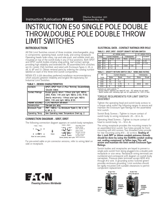
THROW,DOUBLE POLE DOUBLE THROW LIMIT SWITCHESINTRODUCTIONAll E50 Limit Switches consist of three modular, interchangeable, plug-in components: operating head, switch body, and wiring receptacle.Operating heads (side rotary, top and side push, and wobble stick) aremounted on top of the switch body in any of four positions. Both SPDTand DPDT switch bodies employ snap-acting, leaf contact springsproviding high reliability and extended life. All assembled limit switchesare UL Listed, CSA Certified, and rated with Enclosure Types 3, 3S, 4,4X, 6, 6P and 13. Obtain renewal parts by ordering the catalog numberlabeled on each of the three limit switch components.NEMA ICS 2-225 describes preferred installation recommendationswhich assures greatest reliability and longest life expectancy forIndustrial Limit Switches.TORQUE REQUIREMENTS FOR LIMIT SWITCHASSEMBL YTighten the operating head and switch body screws toa torque value within the following ranges to assure andmaintain the Enclosure Type Ratings for the assembledlimit switch.Switch Body Screws – Tighten to insure contact ofswitch body to wiring receptacle: 25 – 30 in.-lb.Operating Head Screws – Tighten to insure contact ofhead to switch body: 14 – 18 in.-lb.The wiring receptacle provides the mounting means foran assembled limit switch. Two holes provide for frontmounting with #10 screws. Two threaded holes providefor rear mounting using #10 – 32 screws. Sealing ofthe ½ inch NPT or 20mm conduit entrance threadsshould be done by using the E50KH6 conduit sealingnut, sealing compound, or T eflon tape. This willassure and maintain the limit switch Enclosure T ypeRatings.Switch bodies and receptacles are keyed to prevent asingle pole switch from being plugged into a double polereceptacle or vice versa. Receptacle wiring terminals arenumbered and correspond with diagram on switch bodynameplate. Pressure plate terminals accept AWG #18through #12 wire. A grounding screw (colored green)provides enclosure grounding. Limit switches shouldbe rigidly mounted with suitable clearances to permitcomponent replacement.CONNECTION DIAGRAM – SPDT, DPDTThe following connection diagram appears on switch body nameplate.ELECTRICAL DATA - CONTACT RATINGS PER POLEFor pre-wired cable or pin connector versions, refer to wiring label onside or receptacle.Contacts SPDT, DPDT Form Z (Four Terminal, Double-Break-Double Make)Contact Ratings Except gravity return: Without pilot light: NEMAA600, R300; With pilot light: NEMA A150, R150;Gravity return-only: Without pilot light: NEMAB600, With pilot light: NEMA B150Repeat Accuracy0.3% maximum deviationConstruction Die-cast zinc alloyEnclosure Type IP67 / NEMA / UL Enclosure Types 3, 3S, 4, 4X,6, 6P, & 13Operating Temp.See Operating Head Temperature Chart pg. 2TABLE 1 - DESIGN CHARACTERISTICS1 N.O. - 1 N.C.Must be same polarityGreen2 N.O. - 2 N.C.Same polarity each poleGrounding: Eachwiring recep-tacle contains agreen screwterminal provinga GRD connecti-on point ot themetal enclosure.16578SINGLEPOLEKEYGROUNDTERMINALSCREWGROUNDTERMINALSCREWDOUBLE POLEKEYSingle PoleWiring ReceptacleDouble PoleWiring ReceptacleTABLE 2 - SPDT, DPDT - EXCEPT GRAVITY RETURN SWITCHContacts on same polarity 1&21 Gravity Return switches are rated AC only - DC ratings do not apply.2 Switch bodies with indicating light are for application on 120V or less.AC (NEMA A600) DC (NEMA R300)Volts Current Amperes Voltamperes CurrentMake Break Cont.Make Break Volts Amperes1206061200.252403032400.12548015 1.510720072060012 1.2TABLE 3 - GRAVITY RETURN SWITCH ONLY - NEMA B600 RATINGAC Current Amperes VoltamperesVolts Make Break Cont.Make Break12030324015 1.54807.50.75 5360036060060.60Instructions Publication P15836Effective November 2011INSTRUCTION E50 SINGLE POLE DOUBLE T HROW,DOUBLE POLE DOUBLE T HROW LIMIT SWITCHESEATON CORPORATION SWITCH BODIES WITH INDICATING LIGHTSwitch bodies with the indicating light should be used at 120V or less. The light is factory-connected. The lamp may be reconnected by lifting the gasket and reconnecting the lightBottom View of Side Operated Rotary Head (Note Mode Change Instructions in Head)Self Operating Head ModeBefore AssemblyPush Operated - These spring return top push or side push operating heads are available in pushbutton and roller styles. The push roller style can be converted from vertical to horizontal operation or vice versa. Pull roller out of the head until it can be rotated 90° to the desired orientation. When released, it will snap into the set position. The Maintained Contact head has the reset pushbutton located opposite of the actuator pushbutton.INSTRUCTION E50 SINGLE POLE DOUBLE T HROW,DOUBLE POLE DOUBLE T HROW LIMIT SWITCHESInstructions Publication P15836Effective November 2011Mechanical life can be extended if the following guidelines are followed:a.) Cam arrangement should be such that: the actuator does not receive a severe impact; the actuator does not suddenly slip back freely.b.) Minimum amount of overtravel should be used. See NEMA ICS 2-225 for additional guidelines.SPECIAL PURPOSE LIMIT SWITCHESGravity Return Limit Switch - These limit switches require a very low operating force. Table 8. The weight of the rod-type lever supplies the return force instead of a return spring. Limit switchoperation is either CW or CCW, and may be mounted in any position where the shaft is horizontal (parallel to ground).Adjustment – After mounting in the selected position, adjust for proper operation. Set the rod extension and lock it in place with set-screw. Loosen other setscrew and rotate the INPUT SHAFT in the direction it will turn when operated (clockwise or counterclockwise) until a resistance is felt and a click is heard (contacts trip). Back the shaft away from this point until the contacts reset as indicated by another click – This is about 10°, the minimum pretravel for the Gravity Return limit switch. The shaft may be set for any desired pre-travel between 10° and 170° - at more than 170° the contacts may trip. In noisy locations, where the click of contact operation might not be heard, connect a test lamp in series with the normally open contacts for visual indication of contact operation. With the shaft set for the desired amount of pretravel, 10° to 170°, lock the operator in place with setscrew. Check for repeatable switch operation. Neutral Position Limit Switch - This spring return limit switch has two independently operated poles. One pole operates when the shaft rotates clockwise, and the other operates when the shaft is rotated counterclockwise. Both poles are reset in the neutral posi-tion (center off). See Table 8 below.T wo Step Limit Switch - The mode of operation of this side rotary operated two pole limit switch can be changed for CW, CCW or CW and CCW mode as described for the standard side rotary head on page 2. Two independently-operated poles function as a degree of head shaft rotation. One pole operates after 10° of shaft rotation and the second after an additional 10° of shaft rotation in the same direc-tion (20° total for step two). Both poles reset when the shaft returns to the spring return or neutral position.Side PushWobble HeadTABLE 7 - OPERATING HEAD DATAInstructions Publication P15836Effective November 2011INSTRUCTION E50 SINGLE POLE DOUBLE T HROW,DOUBLE POLE DOUBLE T HROW LIMIT SWITCHESTABLE 8 - OPERATING DATA - SPECIAL PURPOSE LIMIT SWITCHESGravity ReturnMust be Same Polarity CW CCWNeutral PositionTwo Step312 For CW or CCW only operation. For CW and CCW operation, operating temperature is -20DIMENSION DIAGRAM - Inches [mm]6TOP PUSH OPERATORS - mm [inches]Top Push Roller6Can accomodate both U.S., 29.4 [1.16] x 59.5 [2.34] and DIN,30 [1.18] x 60 [2.36] mounting options.SIDE PUSH OPERATORS - mm [inches]Side Push RollerSide Pushbutton MaintainedSide PushbuttonSide Pushbutton AdjustableTop Pushbutton Adjustable Top Pushbutton7 FOR E50DS48 FOR E50DS3Eaton Corporation Electrical Sector 1111 Superior Ave.Cleveland, OH 44114United States877-ETN-CARE (877-386-2273)© 2011 Eaton Corporation All Rights Reserved Printed in USAPublication No. P15836 / 003November 2011Eaton is a registered trademark of Eaton Corporation.All other trademarks are property of their respective owners.。
安全限位开关说明书
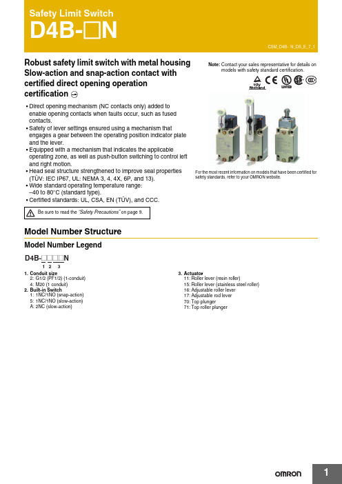
Robust safety limit switch with metal housing Slow-action and snap-action contact with certified direct opening operation•Direct opening mechanism (NC contacts only) added to enable opening contacts when faults occur, such as fused contacts.•Safety of lever settings ensured using a mechanism thatengages a gear between the operating position indicator plate and the lever.•Equipped with a mechanism that indicates the applicableoperating zone, as well as push-button switching to control left and right motion.•Head seal structure strengthened to improve seal properties(TÜV: IEC IP67, UL: NEMA 3, 4, 4X, 6P, and 13).•Wide standard operating temperature range: –40 to 80°C (standard type).•Certified standards: UL, CSA, EN (TÜV), and CCC.Model Number StructureModel Number Legend 1.Conduit size2:G1/2 (PF1/2) (1-conduit)4:M20 (1 conduit)2.Built-in Switch1:1NC/1NO (snap-action)5:1NC/1NO (slow-action) A:2NC (slow-action)3.Actuator11:Roller lever (resin roller)15:Roller lever (stainless steel roller)16:Adjustable roller lever 17:Adjustable rod lever 70:Top plunger71:Top roller plungerFor the most recent information on models that have been certified for safety standards, refer to your OMRON website.Be sure to read the “Safety Precautions” on page 9.Ordering InformationSet Model NumbersConsult with your OMRON representative when ordering any models that are not listed in this table. Safety Limit Switches (with Direct Opening Mechanism)General-purpose Limit SwitchesNote:Consult your OMRON representative for products.SpecificationsStandards and EC DirectivesConforms to the following EC Directives:•Machinery Directive •Low Voltage Directive •EN50041•EN60204-1•EN1088Certified StandardsSnap-action ModelsSlow-action ModelsCertified Standard RatingsTÜV (EN60947-5-1), CCC (GB14048.5)Note:As protection against short-circuiting, use either a gI -type or gG -type 10 A fuse that conforms to IEC60269.UL/CSA: (UL508, CSA C22.2 No. 14)A600ItemUtilization category AC-15Rated operating current (I e ) 2 A Rated operating voltage (U e )400 VRated voltage Carry currentCurrent (A)Volt-amperes (VA)MakeBreakMakeBreak120 VAC 240 VAC 480 VAC 600 VAC10 A 60 30 15 126 3 1.5 1.27,200 720RatingsNote:1.The above values are continuous currents.2.Inductive loads have a power factor of 0.4 or higher (AC) or a time constant of 7 ms or lower (DC).mp loads have a inrush current of 10 times the normal current.4.Motor loads have a inrush current of 6 times the normal current.CharacteristicsNote:1.The above values are initial values.2.The above values may vary depending on the model. Consult your OMRON sales representative for details.*1.The degree of protection is tested using the method specified by the standard (EN60947-5-1). Confirm that sealing properties are sufficient forthe operating conditions and environment beforehand.*2.The durability is for an ambient temperature of 5 to 35°C and ambient humidity of 40% to 70%. For further conditions, consult your OMRONsales representative.*3.The above values may vary depending on switching frequency, environmental condition, and relativity level, consult your OMRON salesrepresentative.Rated voltage (V)Non-inductive load (A)Inductive load (A)Resistive load Lamp loadInductive loadMotor loadNCNONCNONCNONCNO125 VAC 250400101010321.5 1.510.810103531.5 2.51.50.88 VDC 1430125250101060.80.46640.20.13330.20.1101060.80.46640.20.1Inrush current30 A max.Degree of protection *1IP67 (EN60947-5-1)Durability *2Mechanical 30,000,000 operations min. (snap-action)10,000,000 operations min. (slow-action)Electrical500,000 operations min. (10 A resistive load at 250 VAC)Operating speed 1 mm/s to 0.5 m/s Operating frequency Mechanical 120 operations/minute Electrical 30 operations/minute Contact resistance25 m Ω max.Minimum applicable load *3General load 180 mA resistive load at 5 VAC Gold-clad contact 20 mA resistive load at 5 VAC (N-level reference value)Rated insulation voltage (U i )600 V (EN60947-5-1)Rated frequency50/60 HzProtection against electric shock Class I (with ground terminal)Pollution degree (operating environment)3 (EN60947-5-1)Impulse withstand voltage (EN60947-5-1)Between terminals of same polarity2.5 kV (snap-action)/4 kV (slow-action)Between terminals of different polarity4 kV (slow-action)Between eachterminal and ground4 kVInsulation resistance 100 M Ω min. (at 500 VDC) between terminals of the same polarity and between each terminal and non-current-carrying part Contact gap 2 × 2 mm min. (slow-action)2 × 0.5 mm min. (snap-action)Vibration resistance Malfunction 10 to 55 Hz, 0.75 mm single amplitude Shock resistanceDestruction 1,000 m/s 2 min.Malfunction300 m/s 2 min.Conditional short-circuit current100 A (EN60947-5-1)Conventional enclosed thermal current (I the )20 A (EN60947-5-1)Ambient operating temperature –40 to 80°C (with no icing) Ambient operating humidity 95% max.WeightApprox. 250 gEngineering DataElectrical Durability (Snap-action)(Ambient temperature: 5 to 30°C, ambient humidity: 40 to 70%)Structure and NomenclatureStructure250 V AC 125 V AC1,0001,000500500300300100100505030301010480 V AC 250 V AC500 V AC(cos φ = 1)(cos φ = 0.4)O p e r a t i o n s (x 104)O p e r a t i o n s (x 104)S w itching c u rrent (A)S w itching c u rrent (A)Operating fre qu encies: 30 times/min., cos φ = 1Operating fre qu encies: 30 times/min., cos φ = 0.4selection of operation on only oneDirect Opening Mechanism1NO/1NC Contact (Snap-action)1NC/1NO Contact (Slow-action)2NC Contact (Slow-action)Contact FormNote:Terminal numbers are according to EN50013; contact symbols are according to IEC60947-5-1.AMo v a b le contactPl Safety camFixed contact (N C)le contact Safety cam directly p mo b lled apart.Dimensions and Operating Characteristics(Unit: mm)Note:Omitted dimensions are the same as those for the Roller Lever Type ModelsD4B-2@@@N have a G1/2 conduit opening. D4B-4@@@N have a M20 conduit opening.SwitchesNote:Unless otherwise specified, a tolerance of 0.4 mm applies to all dimensions.*1.The lever can be set to any desired position by turning the operating position indicator.*2.In terms of construction, the Switch is a General-purpose Limit Switch rather than a Safety Limit Switch.Note:Variation occurs in the simultaneity of contact opening/closing operations of 2NC contacts. Check contact operation.*1.The operating characteristics of these Switches were measured with the roller level set at 31.5 mm.*2.The operating characteristics of these Switches were measured with the rod level set at 140 mm.*3.Only for slow-action models.*4.Only for snap-action models.*5.Reference values.*6.Must be provided to ensure safe operation.Model Operating characteristics D4B-@@11N D4B-@@15N D4B-@@16N *1D4B-@@17N*2Operating force Release force PretravelOvertravelMovement differential Direct opening travel Direct opening force Total travelOF max.RF min.PTPT (2nd) *3 *5OT min.MD max. *4DOT min. *3 *6*4 *6DOF min. *6TT *59.41N1.47N 21°±3°(45°)50°12°35°55°19.61N (75°)9.41N 1.47N 21°±3°(45°)50°12°35°55°19.61N (75°)9.41N 1.47N 21°±3°(45°)50°12°35°55°19.61N (75°)2.12N 0.29N 21°±3°(45°)50°12°35°55°19.61N (75°)131.325 to Adjustable Roller Lever D4B-@@16NAdjustable Rod Lever D4B-@@17NNote:Unless otherwise specified, a tolerance of ±0.4 mm applies to all dimensions. Operating characteristics Model D4B-@@70N D4B-@@71NOperating force Release force PretravelOvertravel Movement differential Direct opening travel Direct opening force Total travel OF max.RF min.PT max.PT (2nd) *1 *3OT min.MD max. *2DOT min. *4DOF min. *4TT *318.63 N1.96 N2 mm(3 mm)5 mm1 mm3.2 mm49.03 N(7 mm)18.63 N1.96 N2 mm(3 mm)5 mm1 mm3.2 mm49.03N(7 mm)Note:Variation occurs in the simultaneity ofcontact opening/closing operations of2NC contacts. Check contactoperation.*1.Only for slow-action models.*2.Only for snap-action models.*3.Reference values.*4.Must be provided to ensure safeoperation.Free position Operating position FP max.OP38 mm35±1 mm51 mm48±1 mmApplication PrecautionSafety PrecautionsBe sure to read the precautions for All Safety Limit Switches in the website at:/.Indication and Meaning for Safe Use•Do not use the Switch submerged in oil or water, or in locations continuously subject to splashes of oil or water. Doing so may result in oil or water entering the Switch interior. (The IP67 degree of protection specification for the Switch refers to water penetration while the Switch is submersed in water for a specified period of time.)•Always attach the cover after completing wiring and before using the Switch. Also, do not turn ON the Switch with the cover open.Doing so may result in electric shock.MountingUse four M5 screws with washers to mount the standard model. Be sure to apply the proper torque to tighten each screw. Mounting Dimensions (M5)•To change the angle of the lever, loosen the Allen-head bolts on the side of the lever.•The operating position indicator plate * has protruding parts which engage with the lever, thus allowing changes to the lever position by 90°.•The back of the operating position indicator plate * has noprotruding parts. If this plate is turned over and attached, any angle within a 360° range can be set. Do not turn over the plate, however, when using the D4B-@N as a switch with a certified direct opening mechanism. For an SUVA- or BIA-certified application, make sure that the lever engages with the operating position indicator plate securely so that the lever will not slip.*The operating position indicator plate: Refer to page 5. Changes in Head Mounting PositionBy removing the screws on the four corners of the head, the head can be reset in any of four directions. Make sure that no foreign materials will penetrate through the head.Changing the Operating Direction Switches with Roller LeversThe operating direction of the lever can be easily changed without using any tools. It can be set toclockwise operation (CW) or counterclockwise (CCW) operation.Use the procedure given at the right to change the operating direction.Head Co OperatingPrecautions for Safe Use Supplementary comments on what to do or avoid doing, to use the product safely.Precautions for Correct Use Supplementary comments on what to do or avoid doing, to prevent failure to operate, or undesirable effect on product performance.Precautions for Safe Use Precautions for Correct UseD4B-@NWiringDo not connect the bare lead wires directly to the terminals but be sure to connect each of them by using an insulation tube and M3.5 round crimp terminals and tighten each terminal screw within the specified torque range.The proper lead wire is 20 to 14 AWG (0.5 to 2.5 mm 2) in size.Make sure that all crimp terminals come into contact with the casing or cover as shown below, otherwise the cover may not be mounted properly or the D4B-@N may malfunction.Conduit Opening•Make sure that each connector is tightened within the specifiedtorque range.The casing may be damaged if the connector is tightened excessively.•Use an OMRON SC-series Connector (sold separately) that is suited to the cable in diameter.Others•The load for the actuator (roller) of the Switch must be imposed on the actuator in the horizontal direction, otherwise the actuator or•@@17N, theSwitch may telegraph. To avoid telegraphing, take the following precautions.1.Set the lever to operate in one direction.2.Modify the rear end of the dog to an angle of 15° to 30° as3.signals.D dia.dz dia.CasingCo v erT erminal scre wCrimp terminalT erminal scre wCasingT erminal scre wCo v erCrimp terminalCorrectCorrectIncorrectIncorrectCrimp terminalCrimp terminalCrimp terminalCorrectIncorrectRead and Understand This CatalogPlease read and understand this catalog before purchasing the products. Please consult your OMRON representative if you have any questions orcomments.WARRANTYOMRON's exclusive warranty is that the products are free from defects in materials and workmanship for a period of one year (or other period if specified) from date of sale by OMRON.OMRON MAKES NO WARRANTY OR REPRESENTATION, EXPRESS OR IMPLIED, REGARDING NON-INFRINGEMENT, MERCHANTABILITY, OR FITNESS FOR PARTICULAR PURPOSE OF THE PRODUCTS. ANY BUYER OR USER ACKNOWLEDGES THAT THE BUYER OR USER ALONE HAS DETERMINED THAT THE PRODUCTS WILL SUITABLY MEET THE REQUIREMENTS OF THEIR INTENDED USE. OMRON DISCLAIMS ALL OTHER WARRANTIES, EXPRESS OR IMPLIED.LIMITATIONS OF LIABILITYOMRON SHALL NOT BE RESPONSIBLE FOR SPECIAL, INDIRECT, OR CONSEQUENTIAL DAMAGES, LOSS OF PROFITS OR COMMERCIAL LOSS IN ANY WAY CONNECTED WITH THE PRODUCTS, WHETHER SUCH CLAIM IS BASED ON CONTRACT, WARRANTY, NEGLIGENCE, OR STRICT LIABILITY.In no event shall the responsibility of OMRON for any act exceed the individual price of the product on which liability is asserted.IN NO EVENT SHALL OMRON BE RESPONSIBLE FOR WARRANTY, REPAIR, OR OTHER CLAIMS REGARDING THE PRODUCTS UNLESSOMRON'S ANALYSIS CONFIRMS THAT THE PRODUCTS WERE PROPERLY HANDLED, STORED, INSTALLED, AND MAINTAINED AND NOTSUBJECT TO CONTAMINATION, ABUSE, MISUSE, OR INAPPROPRIATE MODIFICATION OR REPAIR.SUITABILITY FOR USEOMRON shall not be responsible for conformity with any standards, codes, or regulations that apply to the combination of products in the customer's application or use of the products.At the customer's request, OMRON will provide applicable third party certification documents identifying ratings and limitations of use that apply to the products. This information by itself is not sufficient for a complete determination of the suitability of the products in combination with the end product, machine, system, or other application or use.The following are some examples of applications for which particular attention must be given. This is not intended to be an exhaustive list of all possible uses of the products, nor is it intended to imply that the uses listed may be suitable for the products:∙Outdoor use, uses involving potential chemical contamination or electrical interference, or conditions or uses not described in this catalog.∙Nuclear energy control systems, combustion systems, railroad systems, aviation systems, medical equipment, amusement machines, vehicles, safety equipment, and installations subject to separate industry or government regulations.∙Systems, machines, and equipment that could present a risk to life or property.Please know and observe all prohibitions of use applicable to the products.NEVER USE THE PRODUCTS FOR AN APPLICATION INVOLVING SERIOUS RISK TO LIFE OR PROPERTY WITHOUT ENSURING THAT THE SYSTEM AS A WHOLE HAS BEEN DESIGNED TO ADDRESS THE RISKS, AND THAT THE OMRON PRODUCTS ARE PROPERLY RATED AND INSTALLED FOR THE INTENDED USE WITHIN THE OVERALL EQUIPMENT OR SYSTEM.PROGRAMMABLE PRODUCTSOMRON shall not be responsible for the user's programming of a programmable product, or any consequence thereof.CHANGE IN SPECIFICATIONSProduct specifications and accessories may be changed at any time based on improvements and other reasons.It is our practice to change model numbers when published ratings or features are changed, or when significant construction changes are made.However, some specifications of the products may be changed without any notice. When in doubt, special model numbers may be assigned to fix or establish key specifications for your application on your request. Please consult with your OMRON representative at any time to confirm actualspecifications of purchased products.DIMENSIONS AND WEIGHTSDimensions and weights are nominal and are not to be used for manufacturing purposes, even when tolerances are shown.PERFORMANCE DATAPerformance data given in this catalog is provided as a guide for the user in determining suitability and does not constitute a warranty. It may represent the result of OMRON’s test conditions, and the users must correlate it to actual application requirements. Actual performance is subject to the OMRON Warranty and Limitations of Liability.ERRORS AND OMISSIONSThe information in this document has been carefully checked and is believed to be accurate; however, no responsibility is assumed for clerical,typographical, or proofreading errors, or omissions.2012.10In the interest of product improvement, specifications are subject to change without notice. OMRON CorporationIndustrial Automation Company/(c)Copyright OMRON Corporation 2012 All Right Reserved.。