马铃薯播种机的性能评估——外文文献翻译、中英文翻译
机械外文文献翻译

Overall position of Agricultural Mechanization inTurkeyAgricultural equipment and machinery are the indispensable part of agricultural activities. If these instruments, which are used in various stages of production, are not used properly, there may be some problems. So, how can we use them properly ? As the proverb goes, “It is the want of care that makes the field bare”. They return the money and efforts invested in them if they are maintained well.Ploughs, which were being used in our country up until recently, resemble those ploughs of the various tribes that lived in Anatolia long time ago. It is because one society gets use of societies that lived before. Some of the black ploughs that were being used up until recently resemble the ploughs that had been used in the ancient Rome.The first agricultural school was established in the Ottoman Empire in 1846. The first domestic heavy ploughs was manufactured i n Izmir 90 years ago, and tractor was introduced 80 years ago. However, it was only the foundation of the Republic that the tractor began to be used in agricultural activities. Agricultural mobilization began with modern agricultural practices in the Atatürk Forest Farm, which was founded by the Great Atatürk. Use of modern agricultural equipment was encouraged, workshops and factories were established, and agricultural machinery was manufactured. Introduction of tractor and particularly its use in agricultural production began in 1938. In those years, tractor use in State Production Farms increased, and farmers recognized the benefits of tractor in agricultural productivity and labor. State production farms became places which clearly showed the importance of agricultural mechanization.Agricultural mechanization is a production technology which enables the appropriate use of energy and equipment required for high production in agricultural area.Warehousing, transporting and marketing the products have become faster and more economic with the help of agricultural mechanization.Tractor is the basic equipment that enables the use of other agricultural equipment. These equipment items are also produced in Turkey. As tractor and other mechanization equipment are expensive, they should be used in a way to achieve the highest productivity and managed by informed and efficient people.Agricultural production in Turkey is Cereal-BasedAgricultural production in Turkey is cereal-based. There are serious nutrition problems in more than the half of the developing countries. Every year, millions of people die of hunger. For this reason, agricultural production is highly important. Turkey is out of it’s available planting areas. They do not have any new places left for plantation. The only thing they can do is to increase productivity. In order to increase productivity, they need to use some imputs. The only way to increase these inputs such as fertilizers, chemicals, irrigation and high quality seedling is agricultural mechanization. It is achieved through ploughing the soil in the right time, planting with a particular plantation row and particular distance in order to utilize equally from all parts of soil, applying chemicals and fertilizers at the requested time and amount, harvesting in a short period and without loss of any grains, and storing the product.Necessary support is given to Turkey’s companiesAgricultural mechanization tools are expensive. However, if they are maintained well and used economically, they return their cost. State provides some opportunities such as low-interest rates for the procurement of Agricultural Mechanization Machineries. The equipment and machinery, which can be purchased with credits, are examined by the units established by the Ministry of Agriculture and Rural Affairs to be approved for the agricultural technique. In these institutions, all kinds of tools and machinery, including tractors, go under various tests. It is determined if these machines are appropriate for Turkey’s environment. Necessary support is given to Turkey’s companies and farmers in order to remove the deficiencies determined.As for the maintenance of these equipment and machinery, it is a great chance that via the improvement of technology, Turkey’s producers are provided withopportunities that will help them in agricultural activities. According to researches,if the maintenance of a machine is done right and on time, purchasing cost decreased by 1/5.农业机械化在土耳其的整体地位农业设备和机械在农业活动中是不可或缺的组成部分。
马铃薯种植机标准

马铃薯种植机标准一、种植机具的分类、型号和基本参数1.1 分类:马铃薯种植机具主要分为两类:手动种植机和自动种植机。
1.2 型号:手动种植机型号包括MS-1,MS-2,MS-3等;自动种植机型号包括AZ-1,AZ-2,AZ-3等。
1.3 基本参数:手动种植机基本参数包括种植深度、种植间距、操作重量等;自动种植机基本参数包括种植深度、种植间距、操作重量、行走速度等。
二、种植机具的安全要求2.1 操作安全:种植机具应设计成使用者易于操作,并避免在操作过程中对使用者造成伤害。
2.2 结构安全:种植机具的结构应稳定可靠,不应有潜在的安全隐患。
2.3 维护安全:种植机具的维护保养部位应易于接近,维护保养操作应安全方便。
三、种植机具的可靠性要求3.1 耐久性:种植机具应具有较长的使用寿命,能在各种环境条件下正常工作。
3.2 稳定性:种植机具应具有良好的稳定性,在连续工作状态下应保持稳定的性能。
3.3 可靠性:种植机具的可靠性应满足使用要求,故障率应低于规定值。
四、种植机具的使用性能要求4.1 播种精度:种植机具的播种精度应满足使用要求,每穴种子数量和间距应控制在规定范围内。
4.2 播种效率:种植机具的播种效率应较高,以满足农业生产的需求。
4.3 适应性:种植机具应能适应不同土壤类型和环境条件下的播种作业。
五、种植机具的试验方法5.1 试验准备:选取代表性样品,进行试验前的检查和准备工作。
5.2 性能试验:对种植机具的性能进行测试和评估,包括播种精度、播种效率、适应性等方面。
5.3 安全试验:对种植机具的安全性能进行测试和评估,包括操作安全性、结构安全性和维护安全性等方面。
六、种植机具的检验规则6.1 出厂检验:所有种植机具在出厂前应进行检验,确保产品质量符合要求。
6.2 型式检验:对于新产品或重要更改的产品,应进行型式检验,以验证其是否满足规定的要求。
6.3 定期检验:对使用中的种植机具应定期进行检验,以确保其持续满足使用性能和安全要求。
育苗播种机外文翻译(中文含外文出处)
这种机制的目的是要获得一个精确的正弦,在轭输入恒量旋转使曲柄臂获得稳定往复的谐波运动。 它由驱动轴,曲柄臂,曲轴,轭,连杆,衬套,连接臂和外壳组成。 选择旋转臂和轭的尺寸以获得60mm的垂直行程长度。这是为了在曲柄臂的半圈中实现喷嘴组件的40mm的对角运动。 剩余的20mm移动提供4 / 12s的停留时间以便于从托盘拾取种子,并且在曲柄臂2 / 12s一转中从喷嘴释放种子。 两个SYM设置在播种机的两侧并通过轴连接以传递旋转运动,以便将平衡的驱动力传递到缩进组件。在两个SYM中,拥有一个具有彼此平行另一个垂直放置的两个磁轭,使得它提供具有901的相位差的垂直和水平往复谐波运动。水平往复运动操作托盘分度机构。由60毫伏/ min -1,2Nm直接耦合的同步电动机给出对SYM的旋转输入运动。
2.2设计注意事项
基于在实验室实验中获得的吸入压力,喷嘴尺寸和MRT的最佳值,设计和制造插塞播种机的原型。 种子设计的基本考虑因素是成本,操作的简便性,便携性以及现成组件的使用以及当地种子的能力,种子单粒化的方法,功能部件的运动学和人体工程学。
一些商业苗圃的调查显示,来自平均规模苗圃的蔬菜幼苗旺季需求量为每天约10万株幼苗,但预计在不久的将来将增加一倍。 通过假设每天运行4小时接种总共有20万个单元格的塞子盘来确定播种机的输出容量。 基于文献综述,选择使用适当尺寸的喷嘴针对单个种子的气动单粒化作为设计原理。 为了最小化成本,选择现成的机电组件,如真空泵,电磁阀,驱动系统,喷嘴,种子管,分度带等。设计并制造非现有的组件。基于操作的容易性调整不同组件的布置和匹配获得匹配兼容性。 在完成设计之前,先考虑人体工程学方面的问题。 托盘平台的总高度保持为770mm,使得托盘可以由坐在椅子上或可能站立的平均印度身高男性放置在分度带上。 不同的控制开关和阀安装在操作者可触及的范围内。 不同功能部件的时间和运动同步按以下顺序进行:
早覆膜马铃薯播种机主要部件设计
3
第一章 绪论
第一章 绪论
人口增加、耕地面积减少、水资源不足以及粮食生产基础还比较脆弱、抗 御自然灾害能力不强等原因,致使中国食物安全存在着潜在危机[1]。目前中国 粮食作物中,水稻、玉米和小麦三大作物占粮食作物总播种面积的 73%左右, 总产量占全部粮食产量的85%左右。按粮食作物种植面积大小排序,马铃薯为 第4个重要的粮食作物,排在水稻小麦玉米之后。但受粮食价格和种粮经济效 益的影响, 三大粮食作物的种植面积短期内仍将保持下降的趋势。 由于三大粮 食作物的平均单产已远高于世界平均水平, 且近年来其单产基本没有增加, 因 此三大粮食作物的总产量亦将呈下降趋势。 虽然目前这种变化趋势对中国食物 安全的影响不是十分明显, 但随着这一趋势进一步发展及人口的自然增加, 将 可能危及中国食物供给的安全决不可小视。 与此相反, 由于比较效益高产业链 长等优势条件,马铃薯的种植面积逐年增加,过去10年净增200多万ha,增幅 达70%。此外在中国南方地区水稻秋收之后每年有1600万ha左右的冬闲田,此 期间的水热光温条件为马铃薯种植提供了良好的气候条件。 近几年不少地区利 用冬闲田种植马铃薯获得了良好的经济效益,使马铃薯冬种面积不断增加。 马铃薯作为一种粮食作物, 在同等条件下其单位面积蛋白质产量分别是小 麦的2倍、水稻的1.3倍和玉米的1.2倍,所含VC是苹果的10倍,VB是苹果的4 倍, 各种矿物质含量是苹果的10倍以上。 马铃薯不但营养齐, 全而且结构合理, 尤其是蛋白质的分子结构与人体的蛋白质分子结构基本一致, 极易被人体吸收 利用,其吸收利用率几乎达到100%。此外,马铃薯还含有其它粮食作物中所 没有的胡萝卜素和抗坏血酸。因此营养学家说“每餐只吃马铃薯和全脂牛奶就 可获得人体所需要的全部营养元素”“马铃薯是十全十美的全价营养食物”[2]
免耕播种机农业用机械外文文献翻译、中英文翻译、外文翻译
中国地质大学长城学院本科毕业设计外文资料翻译系别:工程技术系专业:机械设计制造及其自动化姓名:孙亚鑫学号: 052116222015 年 4 月 1 日外文原文No-tillage drillIt is a significative mission for the persons majoring in agriculture mechanics to spread conservation agriculture, especially in the region adopting the double cropping mode. The culture condition in these areas gives some special problem to drill. For example, it is pressing to plant wheat as the follow course of maize; At that time the stalks cover is so heavy and the stalks are so flexile that the block is serious; The bushy maize root makes the earth surface too rough to drill in the no-tillage procedure; And seed bareness is familiar when adopting machines with gravity-root-broken mechanisms, etc. Presently, most native or foreign no-tillage drill can not finish the work smoothly. Designing and manufacturing row-controlled no-tillage wheat drill have been recited in this article based on the analysis and studies of the intention and principles of the conservation tillage.Nowadays the core problem is anti-blocking in the research and design of no-tillage planters domestic and abroad. Although many agricultural machine experts have made some progress, the anti-blocking problem is not solved in grain. Based on it, through classifying and analyzing the anti-blocking equipment used by no-tillage planters and its principle, contrasting their respective strongpoint and shortcoming, in the light of the mulching stalk property and the contrast of two kinds of cutting methods, the radical theory and general framework project of the sliding cutting type anti-blocking equipment are worked out.A new-concept of no-till wheat planter, named 2BMD-12 no-till row-follow wheat planter, had been developed by China Agricultural University to solve an extremely important problem which is zero tillage planting of wheat in narrow row spacing (150-200mm) between rows of very high-levels full length, standing maize stubble in one pass in the double cropping situation of North China. A powered rotary strip-chopping unit was placed forward of each single row of planter tines to ensure that the above-ground section of the planter tine is kept free from residue blockage. Field performance test of the machine demonstrated that it could be a good choice to work effectively for much of the time under more diffcult residue conditions than that most other planters could tolerate especially when it follows well between the standing maize stubble rows.But there are still some problems existing for the rotary strip-chopping unit, planting unit and ground wheels etc. The thesis focused on improving the design of the machine to solve these problems.(1)The strip-chopping axis was redesigned to reduce vibration and power consumption by adjusting the arrangement of the knives and on the basis of analyzing the forces on the axis. The improved machine can adapt to maize row spacing from 500mm to 700mm.(2)More improvements were done on the planning unit focusing on the blockage and depth control issues. A new anti-blockage mechanism, which combines the powered chopping and disc opener, was designed and tested. Fertilizer was applied using the narrow tine opener with chopping unit in front of each tine; while a double disc opener, which is proved to have highresidue handling capacity, was installed right behind each tine to seed into the fertilizer furrow. This new design reduced the blockage between planting units. Meanwhile seeding depth of each row can be controlled separately by the ground feeling mechanism on each double-disc opener.So do the mode analysis in the finite element analysis software ANSYS and make appropriate remedy for the main frame and the main shaft. Get a compact firm steady model in the software interface.The block can be eliminated when the knives of pulverizes run through the abutted furrow opener stems. The problem of rough seeding bed is avoided in the use of row controlled method. It is more appropriate to the definition of conservative tillage for disturbing less soil. Seeding and fertilization can be finished in the single course in the field with average cover degree of 4kg/㎡. and all maize standing. It can save time, increase soil fertility, lessen the working procedure to use the drill. Finally, it will reduce the agriculture input.外文资料翻译译文免耕播种机在我国广大一年两熟地区大力推广保护性耕作是目前该地区农机工作者的重要任务之一,其意义深远。
马铃薯播种机的性能评估外文翻译、外文文献翻译、机械类中英文翻译
马铃薯播种机的性能评估外文翻译、外文文献翻译、机械类中英文翻译Assessment of the Behaviour of Potatoes in a Cup-belt PlanterH Buitenwerf WB Hoogmoed P LerinkJMullerFarm Technology Group Wageningen University PO Box 17 6700 AA WageningenThe Netherlandse-mail of corresponding author willemhoogmoedwurnlKrone GmbH Heinrich-Krone Strasse 10 48480 Spelle GermanyIB-Lerink Laan van Moerkerken 85 3271AJ Mijnsheerenland The NetherlandsInstitute of Agricultural Engineering University of Hohenheim D-70593 Stuttgart GermanyReceived 27 May 2005 accepted in revised form 20 June 2006 published online 2 August 2006The functioning of most potato planters is based on transport and placement of the seed potatoes by a cup-belt The capacity of this process is rather low when planting accuracy has to stay at acceptable levels The main limitations are set by the speed of the cup-belt and the number andpositioning of the cups It was hypothesised that the inaccuracy in planting distance that is the deviation from uniform planting distances mainly is created by the construction of the cup-belt planter To determine the origin of the deviations in uniformity of placement of the potatoes a theoretical model was built The model calculates the time interval between each successive potato touching the ground Referring to the results of the model two hypotheses were posed one with respect to the effect of belt speed and one with respect to the inuence of potato shape A planter unit was installed in a laboratory to test these two hypotheses A high-speed camera was used to measure the time interval between each successive potato just before they reach the soil surface and to visualise the behaviour of the potatoThe results showed that a the higher the speed of the cup-belt the more uniform is the deposition of the potatoes and b a more regular potato shape did not result in a higher planting accuracy Major improvements can be achieved by reducing the opening time at the bottom of the duct and by improving the design of the cups and its position relative to the duct This will allow more room for changes in the cup-belt speeds while keeping a high planting accuracy1 IntroductionThe cup-belt planter Fig 1 is the most commonly used machine to plant potatoes The seed potatoes are transferred from a hopper to theconveyor belt with cups sized to hold one tuber This belt moves upwards to lift the potatoes out of the hopper and turns over the upper sheave At this point the potatoes fall on the back of the next cup and are conned in a sheet-metal duct At the bottom the belt turns over the roller creating the opening for dropping the potato into a furrow in the soil Capacity and accuracy of plant spacing are the main parameters of machine performance High accuracy of plant spacing results in high yield and a uniform sorting of the tubers at harvest McPhee et al 1996 Pavek Thornton 2003 Field measurements unpublished data of planting distance in The Netherlands revealed a coefcient of variation CV of around 20 Earlier studies in Canada and the USA showed even higher CVs of up to 69 Misener 1982 Entz LaCroix 1983 Sieczka et al 1986 indicating that the accuracy is low compared to precision planters for beet or maizeTravelling speed and accuracy of planting show an inverse correlation Therefore the present cup-belt planters are equipped with two parallel rows of cups per belt instead of one Doubling the cup row allows double the travel speed without increasing the belt speed and thus a higher capacity at the same accuracy is expectedThe objective of this study was to investigate the reasons for the low accuracy of cup-belt planters and to use this knowledge to derive recommendations for design modications eg in belt speeds or shape andnumber of cupsFor better understanding a model was developed describing the potato movement from the moment the potato enters the duct up to the moment it touches the ground Thus the behaviour of the potato at the bottom of the soil furrow was not taken into account As physical properties strongly inuence the efciency of agricultural equipment Kutzbach 1989 the shape of the potatoes was also considered in the modelTwo null hypotheses were formulated 1 the planting accuracy is not related to the speed of the cup-belt and 2 the planting accuracy is not related to the dimensions expressed by a shape factor of the potatoes The hypotheses were tested both theoretically with the model and empirically in the laboratory2 Materials and methods21 Plant materialSeed potatoes of the cultivars cv Sante Arinda and Marfona have been used for testing the cup-belt planter because they show different shape characteristics The shape of the potato tuber is an important characteristic for handling and transporting Many shape features usually combined with size measurements can be distinguished Du Sun 2004 Tao et al 1995 Zodler1969 In the Netherlands grading of potatoes is mostly done by using the square mesh size Koning de et al 1994 which is determined only bythe width and height largest and least breadth of the potato For the transport processes inside the planter the length of the potato is a decisive factor as wellA shape factor S based on all three dimensions was introducedwhere l is the length w the width and h the height of the potato in mm with howol As a reference also spherical golf balls with about the same density as potatoes representing a shape factor S of 100 were used Shape characteristics of the potatoes used in this study are given in Table 122 Mathematical model of the processA mathematical model was built to predict planting accuracy and planting capacity of the cup-belt planter The model took into consideration radius and speed of the roller the dimensions and spacing of the cups their positioning with respect to the duct wall and the height of the planter above the soil surface Fig 2 It was assumed that the potatoes did not move relative to the cup or rotate during their downward movementThe eld speed and cup-belt speed can be set to achieve the aimed plant spacing The frequency fpot of potatoes leaving the duct at the bottom is calculated aswhere vc is the cup-belt speed in ms-1 and xc is the distance in m between the cups on the belt The angular speed of the roller or in rads -1 with radius rr in m is calculated asThis gap xrelease in m is reached at a certain angle arelease in rad of a cup passing the roller This release angle arelease Fig 2 is calculated aswhere rc is the sum in m of the radius of the roller the thickness of the belt and the length of the cup and xclear is the clearance in m between the tip of the cup and the wall of the ductWhen the parameters of the potatoes are known the angle required for releasing a potato can be calculated Apart from its shape and size the position of the potato on the back of the cup is determinative Therefore the model distinguishes two positions a minimum re-quired gap equal to the height of a potato and b imum required gap equal to the length of a potatoThe time trelease in s needed to form a release angle ao is calculated asCalculating trelease for different potatoes and possible positions on the cup yields the deviation from the average time interval between consecutive potatoes Combined with the duration of the free fall and the eld speed of the planter this gives the planting accuracy When the potato is released it falls towards the soil surface As each potato is released on a unique angular position it also has a unique height above the soil surface at that moment Fig 2 A small potato will bereleased earlier and thus at a higher point than a large one The model calculates the velocity of the potato just before it hits the soil surface uend in ms-1 The initial vertical velocity of the potato v0 in ms-1 is assumed to equal the vertical component of the track speed of the tip of the cupwhere yr in m is the distance between the centre of the roller line A in Fig 2 and the soil surfaceThe time of free fall tfall in s is calculated withwhere g is the gravitational acceleration 98ms2 and the nal velocity vend is calculated aswith v0 in ms-1 being the vertical downward speed of the potato at the moment of releaseThe time for the potato to move from Line A to the release point trelease has to be added to tfallThe model calculates the time interval between two consecutive potatoes that may be positioned in different ways on the cups The largest deviations in intervals will occur when a potato positioned lengthwise is followed by one positioned heightwise and vice versa23 The laboratory arrangementA standard planter unit Miedema Hassia SL 4 6 was modied by replacing part of the bottom end of the sheet metal duct with similarly shaped transparent acrylic material Fig 3 The cup-belt was driven viathe roller 8 in Fig 1 by a variable speed electric motor The speed was measured with an infrared revolution meter Only one row of cups was observed in this arrangementA high-speed video camera SpeedCam Pro Wein-berger AG Dietikon Switzerland was used to visualize the behaviour of the potatoes in the transparent duct and to measure the time interval between consecutive potatoes A sheet with a coordinate system was placed behind the opening of the duct the X axis representing the ground level Time was registered when the midpoint of a potato passed the ground line Standard deviation of the time interval between consecutive potatoes was used as measure for plant spacing accuracyFor the measurements the camera system was set to a recording rate of 1000 frames per second With an average free fall velocity of 25ms-1 the potato moves approx 25mm between two frames sufciently small to allow an accurate placement registrationThe feeding rates for the test of the effect of the speed of the belt were set at 300 400 and 500 potatoes min-1 fpot 5 67 and 83s-1 corresponding to belt speeds of 033 045 and 056ms-1 These speeds would be typical for belts with 3 2 and 1 rows of cups respectively A xed feeding rate of 400 potatoes min-1 cup-belt speed of 045ms-1 was used to assess the effect of the potato shapeFor the assessment of a normal distribution of the time intervals 30potatoes in ve repetitions were used In the other tests 20 potatoes in three repetitions were used24 Statistical analysisThe hypotheses were tested using the Fisher test as analysis showed that populations were normally dis-tributed The one-sided upper tail Fisher test was used and a was set to 5 representing the probability of a type 1 error where a true null hypothesis is incorrectly rejected The condence interval is equal to 100--a3 Results and discussion31 Cup-belt speedThe measured time intervals between consecutive potatoes touching ground showed a normal distribution Standard deviations s for feeding rates 300 400 and 500 potatoes min-1 were 330 205 and 127ms respectively According to the F-test the differences between feeding rates were signicant The normal distributions for all three feeding rates are shown in Fig 4 The accuracy of the planter is increasing with the cup-belt speed with CVs of 86 71 and 55 respectively32 Results predicted by the modelFigure 5 shows the effect of the belt speed on the time needed to create a certain opening A linear relationship was found between cup-belt speed and the accuracy of the deposition of the potatoes expressed as deviation from the time interval The shorter the time needed for creating the openingthe smaller the deviations Results of these calculations are given in Table 2The speed of the cup turning away from the duct wall is important Instead of a higher belt speed an increase of the cups circumferential speed can be achieved by decreasing the radius of the roller The radius of the roller used in the test is 0055m typical for these planters It was calculated what the radius of the roller had to be for lower belt speeds in order to reach the same circumferential speed of the tip of the cup as found for the highest belt speed This resulted in a radius of 0025m for 300 potatoes min-1 and of 0041m for 400 potatoes min-1 Compared to this outcome a linear trend line based on the results of the laboratory measurements predicts a imum performance at a radius of around 0020m The mathematical model [Eqn 5 ] predicted a linear relationship between the radius of the roller for r4001m and the accuracy of the deposition of the potatoes The model was used to estimate standard deviations for different radii at a feeding rate of 300 potatoes min-1 The results are given in Fig 6 showing that the model predicts a more gradual decrease in accuracy in comparison with the measured data A radius of 0025m which is probably the smallest radius technically possible should have given a decrease in standard deviation of about 75 compared to the original radius4 ConclusionsThe mathematical model simulating the movement of the potatoes at the time of their release from the cup-belt was a very useful tool leading to the hypotheses to be tested and to design the laboratory test-rig Both the model and the laboratory test showed that the higher the speed of the belt the more uniformthe deposition of the potatoes at zero horizontal velocity This was due to the fact that the opening allowing the potato to drop is created quicker This leaves less effect of shape of the potato and the positioning of the potato on the cup A relationship with the belt speed was found So to provide more room for reductions in the cup-belt speeds while keeping a high planting accuracy it is recommended to decrease the radius of the roller till as low as technically possible This study showed that the accuracy of planting distance in the seeding furrow is inuenced for a large part by the cup-belt unit of the planterA more regular shape lower shape factor does not automatically result in a higher accuracy A sphere golf ball in most cases was deposited with a lower accuracy than a potato This was caused by the shapes of the guiding duct and cupsIt is recommended to redesign the geometry of the cups and duct and to do this in combination with a smaller roller马铃薯播种机的性能评估原文来源H BuitenwerfWB HoogmoedPLerink and J MüllerAssement of the Behavior of Potato in a Cup-belt Planter Biosytems Engineering Volume 95 Issue September 2006 3541大多数马铃薯播种机都是通过勺型输送链对马铃薯种子进行输送和投放当种植精度只停留在一个可接受水平的时候这个过程的容量就相当低主要的限制因素是输送带的速度以及取薯勺的数量和位置假设出现种植距离的偏差是因为偏离了统一的种植距离这主要原因是升运链式马铃薯播种机的构造造成的一个理论的模型被建立来确定均匀安置的马铃薯的原始偏差这个模型计算出两个连续的马铃薯触地的时间间隔当谈到模型的结论时提出了两种假设一种假设和链条速度有关另一种假设和马铃薯的形状有关为了验证这两种假设特地在实验室安装了一个种植机同时安装一个高速摄像机来测量两个连续的马铃薯在到达土壤表层时的时间间隔以及马铃薯的运动方式结果显示a输送带的速度越大播撒的马铃薯越均匀b筛选后的马铃薯形状并不能提高播种精度主要的改进措施是减少导种管底部的开放时间改进取薯杯的设计以及其相对于导种管的位置这将允许杯带在保持较高的播种精度的同时有较大的速度变化空间1介绍说明升运链式马铃薯种植机图一是当前运用最广泛的马铃薯种植机每一个取薯勺装一块种薯从种子箱输送到传送链这条链向上运动使得种薯离开种子箱到达上链轮在这一点上马铃薯种块落在下一个取薯勺的背面并局限于金属导种管内在底部输送链通过下链轮获得足够的释放空间使得种薯落入地沟里图一杯带式播种机的主要工作部件1种子箱2输送链3取薯勺4上链轮5导种管6护种壁7开沟器8下链轮轮9释放孔10地沟株距和播种精确度是评价机械性能的两个主要参数高精确度将直接导致高产以及马铃薯收获时的统一分级在荷兰的实地测量株距未发表的数据变异系数大约为20美国和加拿大早期的研究显示相对于玉米和甜菜的精密播种当变异系数高达69时其播种就精度特别低输送速度和播种精度显示出一种逆相关关系因此目前使用的升运链式种植机的每条输送带上都装备了两排取薯勺而不是一排双排的取薯勺可以使输送速度加倍而且不必增加输送带的速度因此在相同的精度上具有更高的性能是可行的该研究的目的是调查造成勺型带式种植机精度低的原因并利用这方面的知识提出建议并作设计上的修改例如在输送带的速度取薯杯的形状和数量上为了便于理解建立一个模型去描述马铃薯从进入导种管到触及地面这个时间段内的运动过程因此马铃薯在地沟的运动情况就不在考虑之列由于物理因素对农业设备的强烈影响 Kutzbach 1989 通常要将马铃薯的形状考虑进模型中两种零假设被提出来了1播种精度和输送带速度无关2播种精度和筛选后的种薯形状尤其是尺寸无关这两种假设都通过了理论模型以及实验室论证的测试2材料及方法播种材料几种马铃薯种子如圣特阿玲达以及麻佛来都已被用于升运链式播种机测试因为它们有不同的形状特征对于种薯的处理和输送来说种薯块茎的形状无疑是一个很重要的因素许多形状特征在结合尺寸测量的过程中都能被区分出来在荷兰马铃薯的等级主要是由马铃薯的宽度和高度最大宽度和最小宽度来决定的种薯在播种机内部的整个输送过程中其长度也是一个不可忽视的因素形状因子S的计算基于已经提到的三种尺寸此处l是长度w是宽度h是高度单位mm且h w l还有球形高尔夫球其密度和马铃薯密度大致相同作为参考同是在研究中用到的马铃薯的形状特征通过表一给出表一实验中马铃薯及高尔夫球的形状特征品种方形网目尺寸毫米形状因子圣特28–35 146阿玲达35–45 362麻佛来35–45 168高尔夫球 428 10022 建立数学模型数学模型的建立是为了预测升运链式播种机的播种精度和播种性能该模型考虑了滚轴的半径和速度取薯勺的尺寸和间距以及它们相对于导种管壁的位置和地沟的高度如图二模型假设马铃薯在下落的过程中并没有相对于取薯勺移动或者相对于轴转动图二模型模拟过程当取薯杯到达A点的时候模拟开始释放时间是开启一个足够大的空间让土豆顺利通过所需的时间该模型同时也计算出两个连续的马铃薯之间的时间间隔以及马铃薯到达地面自由下落的时间rc 代表链轮半径带的厚度以及取薯杯长度之和xclear 取薯勺与导种管壁之间的间距xrelease 释放的间距αrelease 释放角度ω链轮的角速度C点地沟田间作业速度和输送带速度可设定为达到既定的作物间距的要求马铃薯离开导种管底部的频率fpot 通过如下公式计算式中vc 是勺型输送带的速度单位ms1xc 是带上两个取薯勺之间的距离单位m槽轮的角速度ωr单位rad s1计算如下导种管的间距必须足够大以使得马铃薯能通过并被释放xrelease是当取薯勺以一定的角度αrelease径向通过链轮时的时间间距释放角图二按以下公式进行计算rc单位m是链轮半径链条的厚度以及取薯勺长度之和xclear单位m是取薯勺端面与导种管管壁之间的间隙当马铃薯的各种参数已确定的情况下释放马铃薯的所需角度可以通过计算得到除了形状和尺寸护种壁的马铃薯的位置也具有诀定性的作用因此这个模型区分了两种状态a释放角度αo所需的时间trelease的计算公式如下当马铃薯释放后将直接落到地沟由于每个马铃薯都是在一个特定的角度释放的通常那时都有一个高于地面的高度图二由于小一点的马铃薯释放得早因此通常将小块马铃薯放在大块马铃薯的上方该模型计算出马铃薯刚好落到地沟时的速度υend单位ms1假定垂直方向的初速度等于取薯勺线速度的垂直分量释放高度的计算公式为yrelease yr-rcsinαreleaseyr单位m是链轮中心和地沟的距离自由下落时间的计算公式为g98 ms2是自由落体加速度v0单位 m 是马铃薯释放时垂直下落的初速度终止速度的计算公式为马铃薯从A点移动到释放点的时间trelease还应该加上tfall该模型计算出以不同的方式在取薯勺上定位的两个连续马铃薯之间的时间间隔最大的误差区间将出现在马铃薯由纵向定位趋向轴向定位的过程中反之亦然实验室装置一个标准的播种机可以替换片状导种管底部的类似透明丙烯酸的材料图三输送链通过链轮被变速电动机驱动其速度可以通过一个旋转的红外检测仪测得此装置只能观察一排取薯勺实验室实验台片状导种管底端的右下部被透明的丙烯酸金属片替代右上端正对一个高速摄像机这个摄像机通过透明的导种管对种薯的运动进行摄像记录并测量两个连续马铃薯之间的时间间隔一张坐标图被安放在导种管的开口处X轴平行于地面当种薯的中点通过地面的时候时间就被记录下来了连续种薯之间的时间间隔的标准偏差被用来衡量作物间距的精度为了便于测量测量系统的记录速率设置为1000帧每秒平均自由下落的速度是25 ms-1时种薯每帧的移动距离是25 mm足够小到可以记录准确的位置为了测试链速的影响进料速度被分别设置为300400500个种薯每分钟fpot567和83 s1对应的链速为033045056ms1这些速度分别对应的是321排取薯杯每分钟400个种薯的进料率045 ms1的杯带速度作为一个固定速度来对马铃薯形状的影响进行测评为了评估时间间隔的正态分布30个种薯将被重复使用5次在另一个测试中20个种薯将被重复使用3次24 统计分析对上述假设进行了Fisher测试分析表明总体呈正态分布尾部进行单因素上限分析的Fisher测试被用来检验频率a为5第一类误差然而一个正确的零假设被错误地拒绝了其置信区间等于 100a3 结果与讨论31 输送带速度测得的连续种薯触地的时间间隔呈正态分布进料速度为300400500的标准偏差σ分别为330205127 ms通过F检验可知进料率的差异显著三种进料率的正态分布如图四所示当变异系数分别为8671和55的时候杯带的速度越大则播种机的精度越高图四三种马铃薯进料速率时间间隔的正态分布图32 结果模型预测图五显示了开口形成时间对升运链速度的影响链条的速度与沉积时偏离了时间间隔的种薯的准确性呈线性关系形成开口的时间越短偏差越小计算结果见表二表二模型计算出来的连续种薯之间的时间间隔带速ms1 最大时间间隔与最小时间间隔的时间差 s0·72 17·60·36 29·40·24 42·8 升运链脱离导种管壁的速度是很重要的一个因素相对提高输送带速来说取薯勺线速度可以通过降低链轮的半径来增大实验中使用的链轮半径是0055米是播种机的一般标准为了使取薯勺的线速度达到最高的升运链速度链轮半径必须通过最低的链条速度计算由此得出种薯进料率为每分钟300个和400个的半径分别为0025米和0041米与此相比实验室测量的结果是一条呈线性变化的直线最大的半径约为0020米数学模型预测的结果呈一种线性关系链轮的半径和种薯沉积的精确度呈线性关系该模型用来估计进料率为每分钟300个种薯的标准差其结果如图六所示该模型的预测值与实测数据相比其精度逐渐减小显然0025米可能是技术上可行的最小半径相对于原来的半径的标准差为75图六显示了链轮半径与沉积的种薯时间间隔标准差之间的关系当满足这种关系是线性的其中4 总结这个模拟马铃薯从输送带开始释放的运动的数学模型是一个非常有用的证实假设和设计实验平台的工具模型和实验室的测试都表明链速越高马铃薯在零速度水平沉积得更均匀这是由于开口足够大使得马铃薯下降得越快这对马铃薯的形状和种薯在取薯杯上的定位有一定的影响与链条速度的关系也就随之明确因此在保持高的播种精度时应该提供更多的空间以减小链条的速度建议降低链轮的半径直至低到技术上的可行度该研究显示播种机的取薯勺升运链链对播种精度播种的幅宽有很大的影响附录- 50 -- 49 -。
马铃薯播种机的性能评估中文

马铃薯播种机的性能评估大多数马铃薯种植机的运作基于通过一个传送带运输和安置马铃薯种子。
当种植的准确性不得不保持在可接受的水平时,这种方式的能力是相当低的。
主要限制是由杯带的速度与杯子的数量和定位所决定的。
这是科学家的假设,不准确株距,是偏离均匀株距,主要是由杯带播种机的结构造成的。
为了找到偏差的根本原因,统一安置土豆的理论模型建立了。
该模型计算出每个连续接触地面的马铃薯之间的时间间隔。
根据模型结果,提出两个假设,一个是杯带速度的影响,一个是马铃薯形状的影响一个种植单元被安装在一个实验室里,以测试这两种假设。
一个高速摄像头用来测量每两个连续马铃薯之间的出土时间间隔,并可以看见马铃薯的这种行为。
结果表明杯带的速度越快,马铃薯的落种就越均匀。
而更规则的马铃薯形状并没有产生一个更高的精度。
通过减少在管道底部的开放时间和提高管道设计杯和其相对位置能实现重大提高这将使杯带速度留有更多的改进空间,同时保持高的种植精度。
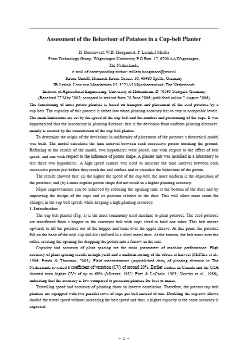
一. 简介杯带播种机是最常用的种植马铃薯的机械。
马铃薯种子是通过一个漏斗输送或一些带有能容纳一个块茎的带杯子的皮带输送。
这种皮带向上移动,把马铃薯从料斗带出并且翻过上滑轮,在这一点上,土豆落在下一个杯的背面,并且被局限在一个金属管里。
在底部,皮带翻过滚筒,以便打开,使马铃薯掉进地上的沟里。
植物间距的容量和准确性是机器性能的主要参数。
在收获时,植物间距的高准确性能获得高产量和统一排序的块茎,在荷兰的种植距离实地测量(未发布的数据)中发现变异(CV)系数在20%左右,在加拿大和美国的较早研究显示变异率更高,变异率达到了 69%。
这说明甜菜或玉米精密播种机的准确性是比较低的。
播种机的行驶速度和种植的准确性呈负相关关系。
因此,目前杯带播种机都配备有两个平行排列的杯,而不是一个。
两个平行排列的杯子提供了两倍的移动速度,并且无需增加传送带的速度,因此这样,在相同精度的条件下,高产量就可以达到了。
本研究的目的是探讨杯带播种机精度低的原因,并依靠得出的结论推导出改装的方案。
马铃薯播种机的性能评估外文翻译、外文文献翻译、机械类中英文翻译
Assessment of the Behaviour of Potatoes in a Cup-belt PlanterH. Buitenwerf; W.B. Hoogmoed; P. Lerink;J.MullerFarm Technology Group, Wageningen University, P.O Box. 17, 6700 AA Wageningen,The Netherlands;e-mail of corresponding author: willem.hoogmoed@wur.nlKrone GmbH, Heinrich-Krone Strasse 10, 48480 Spelle, GermanyIB-Lerink, Laan van Moerkerken 85, 3271AJ Mijnsheerenland, The Netherlands Institute of Agricultural Engineering, University of Hohenheim, D-70593 Stuttgart, Germany(Received 27 May 2005; accepted in revised form 20 June 2006; published online 2 August 2006) The functioning of most potato planters is based on transport and placement of the seed potatoes by a cup-belt. The capacity of this process is rather low when planting accuracy has to stay at acceptable levels. The main limitations are set by the speed of the cup-belt and the number and positioning of the cups. It was hypothesised that the inaccuracy in planting distance, that is the deviation from uniform planting distances, mainly is created by the construction of the cup-belt planter.To determine the origin of the deviations in uniformity of placement of the potatoes a theoretical model was built. The model calculates the time interval between each successive potato touching the ground. Referring to the results of the model, two hypotheses were posed, one with respect to the effect of belt speed, and one with respect to the influence of potato shape. A planter unit was installed in a laboratory to test these two hypotheses. A high-speed camera was used to measure the time interval between each successive potato just before they reach the soil surface and to visualise the behaviour of the potato.The results showed that: (a) the higher the speed of the cup-belt, the more uniform is the deposition of the potatoes; and (b) a more regular potato shape did not result in a higher planting accuracy.Major improvements can be achieved by reducing the opening time at the bottom of the duct and by improving the design of the cups and its position relative to the duct. This will allow more room for changes in the cup-belt speeds while keeping a high planting accuracy.1. IntroductionThe cup-belt planter (Fig. 1) is the most commonly used machine to plant potatoes. The seed potatoes are transferred from a hopper to the conveyor belt with cups sized to hold one tuber. This belt moves upwards to lift the potatoes out of the hopper and turns over the upper sheave. At this point, the potatoes fall on the back of the next cup and are confined in a sheet-metal duct. At the bottom, the belt turns over the roller, creating the opening for dropping the potato into a furrow in the soil.Capacity and accuracy of plant spacing are the main parameters of machine performance. High accuracy of plant spacing results in high yield and a uniform sorting of the tubers at harvest (McPhee et al., 1996; Pavek & Thornton, 2003). Field measurements (unpublished data) of planting distance in The Netherlands revealed a coefficient of variation (CV) of around 20%. Earlier studies in Canada and the USA showed even higher CVs of up to 69% (Misener, 1982; Entz & LaCroix, 1983; Sieczka et al., 1986), indicating that the accuracy is low compared to precision planters for beet or maize.Travelling speed and accuracy of planting show an inverse correlation. Therefore, the present cup-belt planters are equipped with two parallel rows of cups per belt instead of one. Doubling the cup row allows double the travel speed without increasing the belt speed and thus, a higher capacity at the same accuracy is expected.The objective of this study was to investigate the reasons for the low accuracy of cup-belt planters and to use this knowledge to derive recommendations for design modifications, e.g. in belt speeds or shape and number of cups.For better understanding, a model was developed, describing the potato movement from the moment the potato enters the duct up to the moment it touches the ground. Thus, the behaviour of the potato at the bottom of the soil furrow was not taken into account. As physical properties strongly influence the efficiency of agricultural equipment (Kutzbach, 1989), the shape of the potatoes was also considered in the model.Two null hypotheses were formulated: (1) the planting accuracy is not related to the speed of the cup-belt; and (2) the planting accuracy is not related to the dimensions (expressed by a shape factor) of the potatoes. The hypotheses were tested both theoretically with the model and empirically in the laboratory. 2. Materials and methods2.1. Plant materialSeed potatoes of the cultivars (cv.) Sante, Arinda and Marfona have been used for testing the cup-belt planter, because they show different shape characteristics. The shape of the potato tuber is an important characteristic for handling and transporting. Many shape features, usually combined with size measurements, can be distinguished (Du & Sun, 2004; Tao et al., 1995; Zodler,1969). In the Netherlands grading of potatoes is mostly done by using the square mesh size (Koning de et al., 1994), which is determined only by the width and height (largest and least breadth) of the potato. For the transport processes inside the planter, the length of the potato is a decisive factor as well.A shape factor S based on all three dimensions was introduced:where l is the length, w the width and h the height of the potato in mm, with howol. As a reference, also spherical golf balls (with about the same density as potatoes), representing a shape factor S of 100 were used. Shape characteristics of the potatoes used in this study are given in Table 1.2.2. Mathematical model of the processA mathematical model was built to predict planting accuracy and planting capacity of the cup-belt planter. The model took into consideration radius and speed of the roller, the dimensions and spacing of the cups, their positioning with respect to the duct wall and the height of the planter above the soil surface (Fig.2). It was assumed that the potatoes did not move relative to the cup or rotate during their downward movement.The field speed and cup-belt speed can be set to achieve the aimed plant spacing. The frequency fpot of potatoes leaving the duct at the bottom is calculated aswhere vc is the cup-belt speed in ms-1and xc is the distance in m between the cups on the belt. The angular speed of the roller or in rad s -1with radius rr in m is calculated asThis gap xrelease in m is reached at a certain angle arelease in rad of a cup passing the roller. This release angle arelease (Fig. 2) is calculated aswhere: rc is the sum in m of the radius of the roller, the thickness of the belt and the length of the cup; and xclear is the clearance in m between the tip of the cup and the wall of the duct.When the parameters of the potatoes are known, the angle required for releasing a potato can be calculated. Apart from its shape and size, the position of the potato on the back of the cup is determinative. Therefore, the model distinguishes two positions: (a) minimum re-quired gap, equal to the height of a potato; and (b) maximum required gap equal to the length of a potato.The time trelease in s needed to form a release angle ao is calculated asCalculating trelease for different potatoes and possible positions on the cup yields the deviation from the average time interval between consecutive potatoes. Combined with the duration of the free fall and the field speed of the planter, this gives the planting accuracy.When the potato is released, it falls towards the soil surface. As each potato is released on a unique angular position, it also has a unique height above the soil surface at that moment (Fig. 2). A small potato will be released earlier and thus at a higher point than a large one.The model calculates the velocity of the potato just before it hits the soil surface uend in ms-1. The initial vertical velocity of the potato v0 in ms-1 is assumed to equal the vertical component of the track speed of the tip of the cup:where yr in m is the distance between the centre of the roller (line A in Fig. 2) and the soil surface.The time of free fall tfall in s is calculated withwhere g is the gravitational acceleration (9.8ms2) and the final velocity vend is calculated aswith v0 in ms-1 being the vertical downward speed of the potato at the moment of release.The time for the potato to move from Line A to the release point trelease has to be added to tfall.The model calculates the time interval between two consecutive potatoes that may be positioned in different ways on the cups. The largest deviations in intervals will occur when a potato positioned lengthwise is followed by one positioned heightwise, and vice versa.2.3. The laboratory arrangementA standard planter unit (Miedema Hassia SL 4(6)) was modified by replacing par t of the bottom end of the sheet metal duct with similarly shaped transparent acrylic material (Fig. 3). The cup-belt was driven via the roller (8 in Fig. 1), by a variable speed electric motor. The speed was measured with an infrared revolution meter. Only one row of cups was observed in this arrangement.A high-speed video camera (SpeedCam Pro, Wein-berger AG, Dietikon, Switzerland) was used to visualize the behaviour of the potatoes in the transparent duct and to measure the time interval betweenconsecutive potatoes. A sheet with a coordinate system was placed behind the opening of the duct, the X axis representing the ground level. Time was registered when the midpoint of a potato passed the ground line. Standard deviationof the time interval between consecutive potatoes was used as measure for plant spacing accuracy.For the measurements the camera system was set to a recording rate of 1000 frames per second. With an average free fall velocity of 2.5ms-1, the potato moves approx. 2.5mm between two frames, sufficiently small to allow an accurate placement registration.The feeding rates for the test of the effect of the speed of the belt were set at 300, 400 and 500 potatoes min-1(fpot = 5, 6.7 and 8.3s-1) corresponding to belt speeds of 0.33, 0.45 and 0.56ms-1. These speeds would be typical for belts with 3, 2 and 1 rows of cups, respectively. A fixed feeding rate of 400 potatoes min-1 (cup-belt speed of 0.45ms-1) was used to assess the effect of the potato shape.For the assessment of a normal distribution of the time intervals, 30 potatoes in five repetitions were used. In the other tests, 20 potatoes in three repetitions were used.2.4. Statistical analysisThe hypotheses were tested using the Fisher test, as analysis showed that populations were normally dis-tributed. The one-sided upper tail Fisher test was used and a was set to 5% representing the probability of a type 1 error, where a true null hypothesis is incorrectly rejected. The confidence interval is equal to (100--a)%.3. Results and discussion3.1. Cup-belt speedThe measured time intervals betweenconsecutive potatoes touching ground showed anormal distribution. Standard deviations s forfeeding rates 300, 400 and 500 potatoes min-1 were33.0, 20.5 and 12.7ms, respectively. According tothe F-test the differences between feeding rateswere significant. The normal distributions for allthree feeding rates are shown in Fig. 4. Theaccuracy of the planter is increasing with thecup-belt speed, with CVs of 8.6%, 7.1% and 5.5%,respectively.3.2. Results predicted by the modelFigure 5 shows the effect of the belt speed onthe time needed to create a certain opening. A linearrelationship was found between cup-belt speed andthe accuracy of the deposition of the potatoesexpressed as deviation from the time interval. Theshorter the time needed for creating the opening, thesmaller the deviations. Results of these calculationsare given in Table 2.The speed of the cup turning away from the ductwall is important. Instead of a higher belt speed, anincrease of the cup’s circumferential speed can beachieved by decreasing the radius of the roller. Theradius of the roller used in the test is 0.055m,typical for these planters. It was calculated what theradius of the roller had to be for lower belt speeds,in order to reach the same circumferential speed ofthe tip of the cup as found for the highest belt speed.This resulted in a radius of 0.025m for 300 potatoesmin-1 and of 0.041m for 400 potatoes min-1.Compared to this outcome, a linear trend line based on the results of the laboratory measurements predicts a maximum performance at a radius of around 0.020m.The mathematical model [Eqn (5)] predicted a linear relationship between the radius of the roller (for r4001m) and the accuracy of the deposition of the potatoes. The model was used to estimate standard deviations for different radii at a feeding rate of 300 potatoes min-1. The results are given in Fig. 6, showing that the model predicts a more gradual decrease in accuracy in comparison with the measured data.A radius of 0.025m, which is probably the smallest radius technically possible, should have given a decrease in standard deviation of about 75% compared to the original radius.4. ConclusionsThe mathematical model simulating the movement of the potatoes at the time of their release from the cup-belt was a very useful tool leading to the hypotheses to be tested and to design the laboratory test-rig.Both the model and the laboratory test showed that the higher the speed of the belt, the more uniformthe deposition of the potatoes at zero horizontal velocity. This was due to the fact that the opening, allowing the potato to drop, is created quicker. This leaves less effect of shape of the potato and the positioning of the potato on the cup. A relationship with the belt speed wasfound. So, to provide more room for reductions in the cup-belt speeds while keeping a high planting accuracy it is recommended to decrease the radius of the roller till as low as technically possible.This study showed that the accuracy of planting (distance in the seeding furrow) is influenced for a large part by the cup-belt unit of the planter.A more regular shape (lower shape factor) does not automatically result in a higher accuracy. A sphere (golf ball) in most cases was deposited with a lower accuracy than a potato. This was caused by the shapes of the guiding duct and cups.It is recommended to redesign the geometry of the cups and duct, and to do this in combination with a smaller roller.马铃薯播种机的性能评估原文来源:H. Buitenwerf,W.B. Hoogmoed,P. Lerink and J. Müller.Assement of the Behavior of Potato in a Cup-belt Planter. Biosytems. Engineering, Volume 95, Issue, September 2006: 35—41大多数马铃薯播种机都是通过勺型输送链对马铃薯种子进行输送和投放。
- 1、下载文档前请自行甄别文档内容的完整性,平台不提供额外的编辑、内容补充、找答案等附加服务。
- 2、"仅部分预览"的文档,不可在线预览部分如存在完整性等问题,可反馈申请退款(可完整预览的文档不适用该条件!)。
- 3、如文档侵犯您的权益,请联系客服反馈,我们会尽快为您处理(人工客服工作时间:9:00-18:30)。
中国地质大学长城学院本科毕业论文外文资料翻译系别:专业:姓名:学号:20** 年 03月 10 日外文资料翻译译文马铃薯播种机的性能评估大多数马铃薯播种机都是通过勺型输送链对马铃薯种子进行输送和投放。
当种植精度只停留在一个可接受水平的时候这个过程的容量就相当低。
主要的限制因素是:输送带的速度以及取薯勺的数量和位置。
假设出现种植距离的偏差是因为偏离了统一的种植距离,这主要原因是升运链式马铃薯播种机的构造造成的.一个理论的模型被建立来确定均匀安置的马铃薯的原始偏差,这个模型计算出两个连续的马铃薯触地的时间间隔。
当谈到模型的结论时,提出了两种假设,一种假设和链条速度有关,另一种假设和马铃薯的形状有关。
为了验证这两种假设,特地在实验室安装了一个种植机,同时安装一个高速摄像机来测量两个连续的马铃薯在到达土壤表层时的时间间隔以及马铃薯的运动方式。
结果显示:(a)输送带的速度越大,播撒的马铃薯越均匀;(b)筛选后的马铃薯形状并不能提高播种精度。
主要的改进措施是减少导种管底部的开放时间,改进取薯杯的设计以及其相对于导种管的位置。
这将允许杯带在保持较高的播种精度的同时有较大的速度变化空间。
1介绍说明升运链式马铃薯种植机(图一)是当前运用最广泛的马铃薯种植机。
每一个取薯勺装一块种薯从种子箱输送到传送链。
这条链向上运动使得种薯离开种子箱到达上链轮,在这一点上,马铃薯种块落在下一个取薯勺的背面,并局限于金属导种管内.在底部,输送链通过下链轮获得足够的释放空间使得种薯落入地沟里。
图一,杯带式播种机的主要工作部件:(1)种子箱;(2)输送链;(3)取薯勺;(4)上链轮;(5)导种管;(6)护种壁;(7)开沟器;(8)下链轮轮;(9)释放孔;(10)地沟。
株距和播种精确度是评价机械性能的两个主要参数。
高精确度将直接导致高产以及马铃薯收获时的统一分级(McPhee et al, 1996;Pavek & Thornton, 2003)。
在荷兰的实地测量株距(未发表的数据)变异系数大约为20%。
美国和加拿大早期的研究显示,相对于玉米和甜菜的精密播种,当变异系数高达69%(Misener, 1982;Entz & LaCroix, 1983;Sieczka et al, 1986)时,其播种就精度特别低。
输送速度和播种精度显示出一种逆相关关系,因此,目前使用的升运链式种植机的每条输送带上都装备了两排取薯勺而不是一排。
双排的取薯勺可以使输送速度加倍而且不必增加输送带的速度。
因此在相同的精度上具有更高的性能是可行的。
该研究的目的是调查造成勺型带式种植机精度低的原因,并利用这方面的知识提出建议,并作设计上的修改。
例如在输送带的速度、取薯杯的形状和数量上。
为了便于理解,建立一个模型去描述马铃薯从进入导种管到触及地面这个时间段内的运动过程,因此马铃薯在地沟的运动情况就不在考虑之列。
由于物理因素对农业设备的强烈影响(Kutzbach, 1989),通常要将马铃薯的形状考虑进模型中。
两种零假设被提出来了:(1)播种精度和输送带速度无关;(2)播种精度和筛选后的种薯形状(尤其是尺寸)无关。
这两种假设都通过了理论模型以及实验室论证的测试。
2材料及方法2.1 播种材料几种马铃薯种子如圣特、阿玲达以及麻佛来都已被用于升运链式播种机测试,因为它们有不同的形状特征。
对于种薯的处理和输送来说,种薯块茎的形状无疑是一个很重要的因素。
许多形状特征在结合尺寸测量的过程中都能被区分出来(Du & Sun, 2004;Tao et al, 1995;Zödler, 1969)。
在荷兰,马铃薯的等级主要是由马铃薯的宽度和高度(最大宽度和最小宽度)来决定的。
种薯在播种机内部的整个输送过程中,其长度也是一个不可忽视的因素。
形状因子S的计算基于已经提到的三种尺寸:此处l是长度,w是宽度,h是高度(单位:mm),且h<w<l。
还有球形高尔夫球(其密度和马铃薯密度大致相同)作为参考。
同是,在研究中用到的马铃薯的形状特征通过表一给出表一实验中马铃薯及高尔夫球的形状特征品种方形网目尺寸,毫米形状因子圣特 28–35 146阿玲达 35–45 362麻佛来 35–45 168高尔夫球 42.8 1002.2 建立数学模型数学模型的建立是为了预测升运链式播种机的播种精度和播种性能,该模型考虑了滚轴的半径和速度,取薯勺的尺寸和间距,以及它们相对于导种管壁的位置和地沟的高度(如图二)。
模型假设马铃薯在下落的过程中并没有相对于取薯勺移动或者相对于轴转动。
图二,模型模拟过程,当取薯杯到达A点的时候模拟开始。
释放时间是开启一个足够大的空间让土豆顺利通过所需的时间。
该模型同时也计算出两个连续的马铃薯之间的时间间隔以及马铃薯到达地面(自由下落)的时间。
r c 代表链轮半径、带的厚度以及取薯杯长度之和;x clear,取薯勺与导种管壁之间的间距;x release 释放的间距;αrelease ,释放角度;ω, 链轮的角速度;C点,地沟。
田间作业速度和输送带速度可设定为达到既定的作物间距的要求。
马铃薯离开导种管底部的频率f pot 通过如下公式计算:式中:v c是勺型输送带的速度(单位:m s−1),x c 是带上两个取薯勺之间的距离(单位:m).槽轮的角速度ωr(单位:rad s−1)计算如下:导种管的间距必须足够大以使得马铃薯能通过并被释放。
x release是当取薯勺以一定的角度αrelease 径向通过链轮时的时间间距。
释放角(图二)按以下公式进行计算:r(单位:m)是链轮半径,链条的厚度以及取薯勺长度之和;x clear(单位:m)是取薯勺端面c与导种管管壁之间的间隙。
当马铃薯的各种参数已确定的情况下,释放马铃薯的所需角度可以通过计算得到。
除了形状和尺寸,护种壁的马铃薯的位置也具有诀定性的作用,因此,这个模型区分了两种状态:(a)最小需求间距等于马铃薯的高度;(b)最大需求间距等于马铃薯的高度。
释放角度αo所需的时间t release的计算公式如下:当马铃薯释放后,将直接落到地沟。
由于每个马铃薯都是在一个特定的角度释放的,通常那时都有一个高于地面的高度(图二)。
由于小一点的马铃薯释放得早,因此通常将小块马铃薯放在大块马铃薯的上方。
该模型计算出马铃薯刚好落到地沟时的速度υend(单位:m s−1)。
假定垂直方向的初速度等于取薯勺线速度的垂直分量:释放高度的计算公式为:y=y r-r c sinαreleasereleasey(单位:m)是链轮中心和地沟的距离r自由下落时间的计算公式为:g(9.8 m s−2)是自由落体加速度,v(单位: m)是马铃薯释放时垂直下落的初速度。
终止速度的计算公式为:马铃薯从A点移动到释放点的时间t release还应该加上t fall。
该模型计算出以不同的方式在取薯勺上定位的两个连续马铃薯之间的时间间隔。
最大的误差区间将出现在马铃薯由纵向定位趋向轴向定位的过程中,反之亦然。
2.3 实验室装置一个标准的播种机可以替换片状导种管底部的类似透明丙烯酸的材料(图三)。
输送链通过链轮被变速电动机驱动,其速度可以通过一个旋转的红外检测仪测得。
此装置只能观察一排取薯勺。
实验室实验台:片状导种管底端的右下部被透明的丙烯酸金属片替代;右上端正对一个高速摄像机。
这个摄像机通过透明的导种管对种薯的运动进行摄像记录,并测量两个连续马铃薯之间的时间间隔。
一张坐标图被安放在导种管的开口处,X轴平行于地面。
当种薯的中点通过地面的时候时间就被记录下来了。
连续种薯之间的时间间隔的标准偏差被用来衡量作物间距的精度。
为了便于测量,测量系统的记录速率设置为1000帧每秒。
平均自由下落的速度是2.5m s−1时,种薯每帧的移动距离是2.5 mm,足够小到可以记录准确的位置。
为了测试链速的影响,进料速度被分别设置为300、400、500个种薯每分钟。
(f pot =5,6.7和8.3 s−1),对应的链速为0.33,0.45,0.56(m s−1)。
这些速度分别对应的是3、2、1排取薯杯。
每分钟400个种薯的进料率(0.45 m s−1的杯带速度)作为一个固定速度来对马铃薯形状的影响进行测评。
为了评估时间间隔的正态分布,30个种薯将被重复使用5次。
在另一个测试中20个种薯将被重复使用3次。
2.4. 统计分析对上述假设进行了Fisher测试,分析表明:总体呈正态分布。
尾部进行单因素上限分析的Fisher测试被用来检验频率a为5%第一类误差,然而一个正确的零假设被错误地拒绝了。
其置信区间等于(100−a)%3 结果与讨论3.1 输送带速度3.1.1 实证结果测得的连续种薯触地的时间间隔呈正态分布。
进料速度为300、400、500的标准偏差σ分别为33.0、20.5、12.7 ms。
通过F检验可知进料率的差异显著。
三种进料率的正态分布如图四所示。
当变异系数分别为8.6%、7.1%和5.5%的时候,杯带的速度越大则播种机的精度越高。
图四,三种马铃薯进料速率时间间隔的正态分布图3.1.2 结果模型预测图五显示了开口形成时间对升运链速度的影响。
链条的速度与沉积时偏离了时间间隔的种薯的准确性呈线性关系。
形成开口的时间越短,偏差越小。
计算结果见表二:表二模型计算出来的连续种薯之间的时间间隔带速(m s−1)最大时间间隔与最小时间间隔的时间差(s)0·7217·60·3629·40·2442·8升运链脱离导种管壁的速度是很重要的一个因素。
相对提高输送带速来说,取薯勺线速度可以通过降低链轮的半径来增大。
实验中使用的链轮半径是0.055米,是播种机的一般标准。
为了使取薯勺的线速度达到最高的升运链速度,链轮半径必须通过最低的链条速度计算。
由此得出种薯进料率为每分钟300个和400个的半径分别为0.025米和0.041米。
与此相比,实验室测量的结果是一条呈线性变化的直线,最大的半径约为0.020米数学模型预测的结果呈一种线性关系。
链轮的半径和种薯沉积的精确度呈线性关系。
该模型用来估计进料率为每分钟300个种薯的标准差。
其结果如图六所示,该模型的预测值与实测数据相比,其精度逐渐减小。
显然0.025米可能是技术上可行的最小半径,相对于原来的半径的标准差为75%。
图六显示了链轮半径与沉积的种薯时间间隔标准差之间的关系。
当满足r>0·01 m时,这种关系是线性的。
● ,测量数据;,数学模型的数据;■,延长到R < 0 • 01米; -,线性关系;R2,决定系数。
3.2 马铃薯的尺寸和形状实验数据由表三给出。
显示固定进料率为每分钟400个种薯的时间间隔的标准偏差。