经典工科类论文翻译
机械工程外文翻译(适用于毕业论文外文翻译+中英文对照)
Mechanical engineering1.The porfile of mechanical engineeringEngingeering is a branch of mechanical engineerig,itstudies mechanical and power generation especially power and movement.2.The history of mechanical engineering18th century later periods,the steam engine invention hasprovided a main power fountainhead for the industrialrevolution,enormously impelled each kind of mechznicalbiting.Thus,an important branch of a newEngineering –separated from the civil engineering tools andmachines on the branch-developed together with Birmingham andthe establishment of the Associantion of Mechanical Engineersin 1847 had been officially recognized.The mechanicalengineering already mainly used in by trial and error methodmechanic application technological development into professional engineer the scientific method of which in theresearch,the design and the realm of production used .From themost broad perspective,thedemend continuously to enhance theefficiencey of mechanical engineers improve the quality of work,and asked him to accept the history of the high degreeof education and training.Machine operation to stress not only economic but also infrastructure costs to an absolute minimun.3.The field of mechanical engineeringThe commodity machinery development in the develop country,in the high level material life very great degree is decided each kind of which can realize in the mechanical engineering.Mechanical engineers unceasingly will invent the machine next life to produce the commodity,unceasingly will develop the accuracy and the complexity more and more high machine tools produces the machine.The main clues of the mechanical development is:In order to enhance the excellent in quality and reasonable in price produce to increase the precision as well as to reduce the production cost.This three requirements promoted the complex control system development.The most successful machine manufacture is its machine and the control system close fusion,whether such control system is essentially mechanical or electronic.The modernized car engin production transmission line(conveyer belt)is a series of complex productions craft mechanization very good example.The people are in the process of development in order to enable further automation of the production machinery ,the use of a computer to store and handle largevolumes of data,the data is a multifunctional machine tools necessary for the production of spare parts.One of the objectives is to fully automated production workshop,threerotation,but only one officer per day to operate.The development of production for mechanical machinery must have adequate power supply.Steam engine first provided the heat to generate power using practical methods in the old human,wind and hydropower,an increase of engin .New mechanical engineering industry is one of the challenges faced by the initial increase thermal effciency and power,which is as big steam turbine and the development of joint steam boilers basically achieved.20th century,turbine generators to provide impetus has been sustained and rapid growth,while thermal efficiency is steady growth,and large power plants per kW capital consumption is also declining.Finally,mechanical engineers have nuclear energy.This requires the application of nuclear energy particularly high reliability and security, which requires solving many new rge power plants and the nuclear power plant control systems have become highly complex electroonics,fluid,electricity,water and mechanical parts networks All in all areas related to the mechanical engineers.Small internal combustion engine,both to the type(petrol and diesel machines)or rotary-type(gas turbines and Mong Kerr machine),as well as their broad application in the field of transport should also due to mechanical enginerrs.Throughout the transport,both in the air and space,or in the terrestrial and marine,mechanial engineers created a variety of equipment and power devices to their increasing cooperation with electrical engineers,especially in the development of appropration control systems.Mechanical engineers in the development of military weapons technology and civil war ,needs a similar,though its purpose is to enhance rather than destroy their productivity.However.War needs a lot of resources to make the area of techonlogy,many have a far-reaching development in peacetime efficiency.Jet aircraft and nuclear reactors are well known examples.The Biological engineering,mechanical engineering biotechnology is a relatively new and different areas,it provides for the replacement of the machine or increase the body functions as well as for medical equipment.Artficial limbs have been developed and have such a strong movement and touch response function of the human body.In the development of artificial organ transplant is rapid,complex cardiac machines and similar equipment to enable increasingly complexsurgery,and injuries and ill patients life functions can be sustained.Someenviromental control mechanical engineers through the initial efforts to drainage or irrigation pumping to the land and to mine and ventilation to control the human environment.Modern refrigeration and air-conditioning plant commonaly used reverse heat engine,where the heat from the engine from cold places to more external heat.Many mechanical engineering products,as well as other leading technology development city have side effects on the environment,producingnoise,water and air pollution caused,destroyed land and landscape.Improve productivity and diver too fast in the commodity,that the renewable natural forces keep pace.For mechanical engineers and others,environmental control is rapidly developing area,which includes a possible development and production of small quantities of pollutants machine sequnce,and the development of new equipment and teachnology has been to reduce and eliminate pollution.4.The role of mechanical engineeringThere are four generic mechanical engineers in common to the above all domains function.The 1st function is the understanding and the research mechanical sciencefoundation.It includes the power and movement of the relationship dynamics For example,in the vibration and movement of the relationship;Automaticcontrol;Study of the various forms of heart,energy,power relations between the thermodynamic;Fluidflows; Heat transfer; Lubricant;And material properties.The 2nd function will be conducts the research,thedesing and the development,this function in turn attempts to carry on the essential change to satisfy current and the future needs.This not only calls for a clear understanding of mechanical science,and have to break down into basic elements of a complex system capacity.But also the need for synthetic and innovative inventions.The 3rd function is produces the product and the power,includeplan,operation and maintenance.Its goal lies in the maintenance either enhances the enterprise or the organization longer-tern and survivabilaty prestige at the same time,produces the greatest value by the least investments and the consumption.The 4th function is mechanical engineer’s coordinated function,including the management,theconsultation,as well as carries on the market marking in certain situation.In all these function,one kind unceasingly to use thescience for a long time the method,but is not traditional or the intuition method tendency,this is a mechanical engineering skill aspect which unceasingly grows.These new rationalization means typical names include:The operations research,the engineering economics,the logical law problem analysis(is called PABLA) However,creativity is not rationalization.As in other areas,in mechanicalengineering, to take unexpected and important way to bring about a new capacity,still has a personal,markedcharacteristice.5.The design of mechanical engineeringThe design of mechanical is the design has the mechanical property the thing or the system,suchas:the instrument and the measuring appliance in very many situations,the machine design must use the knowledge of discipline the and so on mathematics,materials science and mechanics.Mechanical engineering desginincludeing all mechanical desgin,but it was a study,because it also includes all the branches of mechsnicalengineering,such as thermodynamics all hydrodynamics in the basic disciplines needed,in the mechanical engineering design of the initial stude or mechanical design.Designstages.The entire desgin process from start to finish,in the process,a demand that is designed forit and decided to do the start.After a lot of repetition,the final meet this demand by the end of the design procees and the plan.Designconsiderations.Sometimes in a system is to decide which parts needs intensity parts of geometric shapes and size an important factor in this context that we must consider that the intensity is an important factor in the design.When we use expression design considerations,we design parts that may affect the entire system design features.In the circumstances specified in the design,usually for a series of such functions must be taken into account.Howeever,to correct purposes,we should recognize that,in many cases the design of important design considerations are not calculated or test can determine the components or systems.Especiallystudents,wheen in need to make important decisions in the design and conduct of any operation that can not be the case,they are often confused.These are not special,they occur every day,imagine,forexample,a medical laboratory in the mechanical design,from marketing perspective,people have high expectations from the strength and relevance of impression.Thick,and heavy parts installed together:to produce a solid impression machines.And sometimes machinery and spare parts from the design style is the point and not theother point of view.Our purpose is to make those you do not be misled to believe that every design decision will need reasonable mathematical methods.Manufacturing refers to the raw meterials into finished products in the enterprise.Create three distinct phases.Theyare:input,processingexprot.The first phase includes the production of all products in line with market needs essential.First there must be the demand for the product,the necessary materials,while also needs such as energy,time,human knowledge and technology resourcess . Finall,the need for funds to obtain all the other resources. Lose one stage after the second phase of the resources of the processes to be distributed.Processing of raw materials into finished products of these processes.To complete the design,based on the design,and then develop plans.Plan implemented through various production processes.Management of resources and processes to ensure efficiency and productivity.Forexample,we must carefully manage resources to ensure proper use of funds.Finally,people are talking about the product market was cast.Stage is the final stage of exporting finished or stage.Once finished just purchased,it must be delivered to the users.According to productperformance,installation and may have to conduct further debugging in addition,someproducts,especially those very complex products User training is necessary.6.The processes of materials and maunfacturingHere said engineering materials into two main categories:metals and non-ferrous,high-performance alloys and power metals.Non-metallic futher divided into plastice,syntheticrubber,composite materials and ceramics.It said the production proccess is divided into several major process,includingshape,forging,casting/founding,heattreatment,fixed/connections ,measurement/ quality control and materalcutting.These processes can be further divide into each other’s craft.Various stages of the development of the manufacturing industry Over the years,the manufacturing process has four distinct stages of development, despite the overlap.These stages are:The first phase is artisanal,the second Phase is mechanization.The third phase is automation the forth Phase is integrated.When mankind initial processing of raw materials into finished products will be,they use manual processes.Each with their hands and what are the tools manusllyproduced.This is totally integrated production take shape.A person needsindentification,collectionmaterials,the design of a product to meet that demand,the production of such products and use it.From beginning to end,everything is focused on doing the work of the human ter in the industrial revolution introduced mechanized production process,people began to use machines to complete the work accomplished previously manual. This led to the specialization.Specialization in turn reduce the manufacture of integrated factors.In this stage of development,manufacturing workers can see their production as a whole represent a specific piece of the part of the production process.Onecan not say that their work is how to cope with the entire production process,or how they were loaded onto a production of parts finished.Development of manufacting processes is the next phase of the selection process automation.This is a computer-controlled machinery and processes.At this stage,automation island began to emerge in the workshop lane.Each island represents a clear production process or a group of processes.Although these automated isolated island within the island did raise the productivity of indivdualprocesses,but the overall productivity are often not change.This is because the island is not caught in other automated production process middle,but not synchronous withthem .The ultimate result is the efficient working fast parked through automated processes,but is part of the stagnation in wages down,causingbottlenecks.To better understand this problem,you can imagine the traffic in the peak driving a red light from the red Service Department to the next scene. Occasionally you will find a lot less cars,more than being slow-moving vehicles,but the results can be found by the next red light Brance.In short you real effect was to accelerate the speed of a red Department obstruction offset.If you and other drivers can change your speed and red light simultaneously.Will advance faster.Then,all cars will be consistent,sommthoperation,the final everyone forward faster.In the workshop where the demand for stable synchronization of streamlined production,and promoted integration of manufacturing development.This is a still evolving technology.Fully integrated in the circumstances,is a computer-controllrd machinery and processing.integrated is completed through computer.For example in the preceding paragraph simulation problems,the computer will allow all road vehicles compatible with the change in red.So that everyone can steady traffic.Scientific analysis of movement,timing and mechanics ofthe disciplines is that it is composed of two pater:statics and dynamics.Statics analyzed static system that is in the system,the time is not taken into account,research and analysis over time and dynamics of the system change.Dynameics from the two componets.Euler in 1775 will be the first time two different branches: Rigid body movement studies can conveniently divided into two parts:geometric and mechanics.The first part is without taking into account the reasons for the downward movement study rigid body from a designated location to another point of the movement,and must use the formula to reflect the actual,the formula would determine the rigid body every point position. Therefore,this study only on the geometry and,morespecifically,on the entities from excision.Obviously,the first part of the school and was part of a mechanical separation from the principles of dynamics to study movement,which is more than the two parts together into a lot easier.Dynamics of the two parts are subsequently divided into two separate disciplines,kinematic and dynamics,a study of movement and the movement strength.Therefore,the primary issue is the design of mechanical systems understand its kinematic.Kinematic studies movement,rather than a study ofits impact.In a more precise kinematic studies position,displacement,rotation, speed,velocity and acceleration of disciplines,foresample,or planets orbiting research campaing is a paradigm.In the above quotation content should be pay attention that the content of the Euler dynamics into kinematic and rigid body dynamics is based on the assumption that they are based on research.In this very important basis to allow for the treatment of two separate disciplines.For soft body,soft body shape and even their own soft objects in the campaign depends on the role of power in their possession.In such cases,should also study the power and movement,and therefore to a large extent the analysis of the increased complexity.Fortunately, despite the real machine parts may be involved are more or less the design of machines,usually with heavy material designed to bend down to the lowest parts.Therefore,when the kinematic analysis of the performance of machines,it is often assumed that bend is negligible,spare parts are hard,but when the load is known,in the end analysis engine,re-engineering parts to confirm this assnmption.机械工程1.机械工程简介机械工程是工程学的一个分支,它研究机械和动力的产,尤其是力和动力。
机械专业英语短文带翻译
机械工程师的关键责任之一是设计与分析机械系统。这涉及使用计算机辅助设计(CAD)软件创建系统的详细三维模型,并在不同条件下模拟其性能。通过分析作用于系统组件的力、应力和振动,机械工程师可以优化设计,确保安全、可靠和高效。
Case Study: Designing an Automotive Suspension System
案例研究:汽车悬挂系统设计
例如,让我们考虑一下汽车悬挂系统的设计。悬挂系统负责在保持车辆稳定控制的同时提供平稳的行驶。机械工程师使用CAD软件设计悬挂系统的各个组件,例如弹簧、减振器和控制臂。
在完成初始设计后,工程师将使用有限元分析(FEA)软件对系统进行分析。这样可以模拟系统在不同的道路条件下(如坑洼或减速带)的行为。通过分析组件中的应力和位移,工程师可以确定潜在的设计问题,并进行必要的修改,以改善悬挂系统的性能和安全性。
For example, let's consider the design of an automotive suspension system. A suspension system is responsible for providing a smooth ride while maintaining the stability and control of the vehicle. A mechanical engineer would use CAD software to design the various components of the suspension system, such as the springs, dampers, and control arms.
After the initial design is complete, the engineer would then analyze the system using finite element analysis (FEA) software. This allows them to simulate the behavior of the system under different road conditions, such as potholes or speed bumps. By analyzing the stresses and displacements in the components, the engineer can identify potential design issues and make necessary modifications to improve the performance and safety of the suspension system.
机械类英语论文及翻译
机械类英语论文及翻译Mechanical design involves the n of machines。
which are composed of mechanisms and other components that can transform and transmit ___ machines include engines。
turbines。
vehicles。
hoists。
printing presses。
washing machines。
and ___ and methods of design that apply to machines also apply to ___。
the term "mechanical design" is used in a broader sense than "machine design" to include their design.When ___。
___ to take into account。
The n and structural aspects of the device。
as well as the ___。
___ apply not only to machines but also to other mechanical devices。
such as switches。
cams。
valves。
vessels。
and mixers.Mechanical design is a critical field in ___ disciplines。
It plays an essential role in the ___ the success of a mechanical design project。
it is essential to follow a set of rules for design。
毕业论文--翻译原文
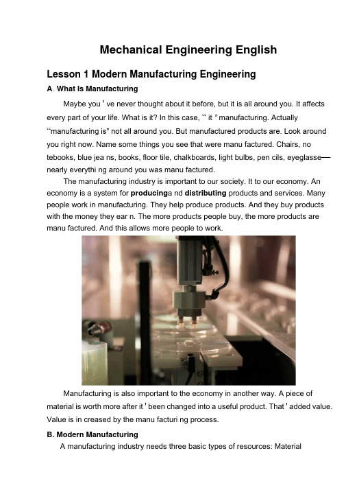
Mechanical Engineering EnglishLesson 1 Modern Manufacturing EngineeringA. What Is ManufacturingMaybe you ' ve never thought about it before, but it is all around you. It affects every part of your life. What is it? In this case, “ it ” manufacturing. Actually “manufacturing is” not all around you. But manufactured products are. Look around you right now. Name some things you see that were manu factured. Chairs, no tebooks, blue jea ns, books, floor tile, chalkboards, light bulbs, pen cils, eyeglasse—nearly everythi ng around you was manu factured.The manufacturing industry is important to our society. It to our economy. An economy is a system for producing a nd distributing products and services. Many people work in manufacturing. They help produce products. And they buy products with the money they ear n. The more products people buy, the more products are manu factured. And this allows more people to work.Manufacturing is also important to the economy in another way. A piece of material is worth more after it ' been changed into a useful product. That ' added value. Value is in creased by the manu facturi ng process.B. Modern ManufacturingA manufacturing industry needs three basic types of resources: Materialresources, Huma n resources C apital resources.The elements of industry are seven key steps for organizing producti on: Research and Developme nt, Producti on Tooli ng, Producti on Planning and Control, Quality Control, Personnel Management, Manu facturi ng, Marketi ng.R&D is the planning of new products, processes,or materials and the improvement of old skill. R&D is such a large, important part of the in dustrial world and requires many people with differe nt tale nts.Producti on Tooli ng is the eleme nt of in dustry concerned with these tools. The PT obta ins the tools, mach in es, and equipme nt n eeded to make a product.The most important parts of Production Planning and Control are routing, scheduling dispatching and plan layout. The machinery and equipme nt must be arran ged so that producti on can take place smoothly, without wasted time and effort.Quality Control can be defined as those activities which prevent defective articles. In this way management tries to insure that a product will be acceptable to the buyer.Marketing is the process of getting products from those who make them to those who use them and it helps to deliver the right kinds of goods to us, in the right formand amount, at the time and price.Lesson 2 Mechanical Engineering DesignMechanical engineering design is a major segment of engineering, it deals with the conception, design, development, refinement, and application of machines and mechanical apparatus of all kinds. For many students, mechanical engineering design is one of their first professional engineering courses. Professional engineering is concerned with obtaining solutions to practical problems, and the engineers are able to devise better solutions to practical problems. The most problems in mechanical engineering design do not have a single right answer. Hence, modern mechanical engineers are able to produce distinctly better solutions to meet today ' s needs. The engineer must use the best availablescientific understanding together with empirical information, good judgment. When considering a complete machine, the enginee in r variably finds that the requirements and constraints of the various components are interrelated. The modern engineer has become increasingly concerned with the broader considerations of safety,ecology, and overall “ quality oflife. ”Good designs require trying new ideas and being willing to take a certain amount of risk, knowing that if the new idea does not work the existing method can be reinstated.Thus a designer must have patience, since there is no assurance of success for the time and effort expanded. Creating a completely new design generally requires that many old and well-established methods be thrust aside. This is not easy since many people cling to familiar ideas, techniques and attitudes. A design engineer should constantly search for ways to improve an existing product and must decide what old, proven concepts should be used and what new, untried ideas should be incorporated.New designs generally have “ bugs”or unforeseen problems which must be worked out before the superior characteristics of the new design can be enjoyed. Thus there is a chance for a superior product, but only at higher risk. It should be emphasizedthat, if a design does not warrant radical new methods, such methods should not be applied merely for the sake of change.During the beginning stages of design, creativity should be allowed to flourish without a great number of constraints. Even though many impractical ideas may arise,it is usually easy to eliminate them in the early stages of design before firm details are required by manufacturing. In this way, innovative ideas are not inhibited. Quite often, more than one design is developed, up to the point where they can be compared against each other. It is entirely possible that the design which is ultimately accepted will use ideas existing in one of the rejected designs that did not show as much overall promise.Another important point which should be recognized is that a design engineer must be able to communicate ideas to other people if they are to be incorporated. Communicating the design to others is the final, vital step in the design process. Undoubtedly many great designs, inventions, and creative works have been lost to mankind simply because the originators were unable or unwilling to explain their accomplishments to others. Presentation is a selling job. The engineer, when presenting a new solution to administrative, management, or supervisory persons, is attempting to sell or to prove to them that this solution is a better one. Unless this can be done successfully, the time and effort spent on obtaining the solution have been largely wasted.。
河北工程大学毕业论文外文翻译

外文翻译:Fundamentals Of Machine ToolsIn many cases products from the primary forming processes must undergo further refinements in size and surface finish to meet their design specification. To meet such precise tolerances the removal of small amounts of material is needs. Usually machine tools are used for such operation.In the United States material removal is a big business--in excess of $93610 per year, including material, labor, overhead, and machine-tool shipments. Since 60 percent of the mechanical and industry engineering and technology graduates have something connected with the machining industry either through sale, design, or operation of machine shops, or working in related industry, it is wise for an engineering student to devote some time in his curriculum to studying material removal and machine tools.A machine tool provides the means for cutting tools to shape a workpiece a required dimensions; the machine supports the tool and the workpiece in a controlled relationship through the functioning of its basic member, which are as follows:(1) Bed, Structure or Frame. This is the main member which provides a basis for, and a connection between, the spindles and slides; the distortion and vibration under load must be kept to a minimum.(2) Slides and Slideways. The translation of a machine element (e.g. the slide) is normally achieved by straight-line motion under the constraint of accurateguiding surfaces (the sildeway).(3) Spindles and Bearings. Angular displacements take place about an axis of rotation; the position of this axis must be constant within extremely fine limits in machine tools, and is ensured by the provision of precision spindles and bearings.(4) Power Unit. The electric motor is the universally adopted power unit for machine tools. By suitably positioning individual motors, belt and gear transmissions are reduced to a minimum.(5) Transmission Linkage. Linkage is the general term used to denote the mechanical, hydraulic, pneumatic mechanisms which connect angular and linear displacements in defined relationship.There are two broad divisions of machining operations:(1) Roughing, for which the mental removal rate, and consequently the cutting force, is high, but the required dimensional accuracy relatively low.(2) Finishing, for which the metal removel rate, and consequently the cutting force, is low, but the required dimensional accuracy and surface finish relatively high.It follows that static loads and dynamic loads, such as result form an unbalanced grindingwheel, are more significant in finishing operations than in roughing operations. The degree of precision achieved in any machining process will usually be influenced by the magnitude of the deflections, which occur as a result of the force acting.Machine tool frames are generally made in cast iron, although some may besteel casting or mild-steel fabrications. Cast iron is chosen because of its cheapness, rigidity, compressive strength and capacity for damping the vibration set-up in machine operations. To avoid massive sections in castings, carefully designed systems of ribbing are box and diagonal. The box formation is convenient to produce, apertures in walls permitting the positioning and extraction of cores. Diagonal ribbing provides greater torsional stiffness and yet permits swarf to fall between the sections; it is frequently used for lathe beds.The slides and slideways of a machine tool lacate and guide members which move relative to each other, usually changing the position of the tool relative to the workpiece. The movement generally takes the form of translation in a straight line, but is sometimes angular rotation, e.g. tilting the wheel-head of a universal thread-grinding machine to an angle corresponding with the helix angle of the workpiece threads. The basic geometric elements of slides are flat, vee, dovetail and cylinder. These elements may used separately or combined in various ways according to the applications. Features of slideways are as follows:(1) Accuracy of Movement. Where a slide is to be displaced in a straight line, this line must lie in two mutually perpendicular planes and there must be no slide rotation. The general tolerance for straightness of machine tool slideways is 0~0.02 mm per 1000 mm; on horizontal surfaces this tolerance may be disposed so that a convex surface results, thus countering the effect of “sag” of the slideway.(2) Means of Adjustment. To facilitate assembly, maintain accuracy and eliminate “play” between sliding members afte r wear has taken place, a strip issometimes inserted in the slides. This is called a gib-strip. Usually, the gib is retained by socket-head screws passing through elongated slots; and is adjusted by grub-screws secured by lock nuts.(3) Lubrication. Slideways may be lubricated by either of the following systems:(i) Intermittently, through grease or oil nipples, a method suitable where movements are infrequent and speed low.(ii) Continuously, e.g. by pumping through a metering valve and pipe-work to the point of application; the film of oil introduced between surfaces by these means must be extremely thin to avoid the slide “floating”. If sliding surfaces were optically flat oil would be squeezed out, resulting in the surfaces sticking. Hence in practice slide surfaces are either ground using the edge of a cup wheel, or scraped. Both processes produce minute surface depressions which retain “pocket” of oil, and complete separation of the parts may not occur at all points ; positive location of the slides is thus retained.(4).Protection. To maintain slideways in good order, the following conditions must be met:(i) Ingress of foreign matter, e.g. swarf, must be prevented. Where this is no possible, it is desirable to have a form of slideway, which does not retain swarf, e.g. the inverted vee.(ii) Lubricating oil must be retained. The adhesive property of oil for use on vertical or inclined slide surface is important; oils are available which have beenspecially developed for this purpose. The adhesiveness of oil also prevents it being washed away by cutting fluids.(iii) Accidental damage must be prevented by protective guards.LathesA machine tool performs three major functions: (i) it rigidly supports the workpiece or its holder and the cutting tool; (ii) it provides relative motion between the workpiece and the cutting tool; (iii) it provides a range of feeds and speeds.Machines used to remove metal in the form of chips are classified as follows: Machines using basically the single-point cutting tools include: engine lathes, turret lathes tracing and duplicating lathes, single-spindle automatic lathes, multi-spindle automatic lathes, shapers and planers, boring machines.Machines using multipoint cutting tools include: drilling machines, milling machines, broaching machines, sawing machines, gear-cutting machines.Machines using random-point cutting tools (abrasive) include: cylindrical grinder, centreless grinders, surface grinders.Special metal removal methods include: chemical milling, electrical discharge machining, ultrasonic machining.The lathe removes material by rotating the workpiece against a cutter to produce external or internal cylindrical or conical surfaces. It is commonly used for the production of surfaces by facing, in which the work piece is rotated while the cutting tool is moved perpendicularly to the axis of rotation.The engine lathe, is the basic turning machine from which other turning machines have been developed. The drive motor is located in the base and drives the spindle through a combination of belts and gears. The spindle is a sturdy hollow shaft, mounted between heavy-duty bearings, with the forward end used for mounting a drive plate to the spindle by threads, by a cam lock mechanism, or by a threaded collar and key.The lathe bed is cast iron and provides accurately ground sliding surfaces (way) on which the carriage rides. The lathe carriage is an H-shaped casting on which the cutting tool is mounted in a tool holder. The apron hangs from the front of the carriage and contains the driving gears that move the tool and carriage along or across the way to provide the desired tool motion.A compound rest, located above the carriage, provides for rotation of the tool holder through any desired angle. A hand wheel and feed screw are provided on the compound rest for linear motions of the tool. The cross feed is provided with another hand wheel and feed screw for moving the compound rest perpendicular to the lathe way. A gear train in the apron provides power feed for the carriage both along and across the way. The feed box contains gears to impart motion to the carriage and control the rate at which the tool moves relative to the workpiece. Since the transmission in the feed box is driven from the spindle gears, the feeds are directly related to the spindle speed. The feed box is gearing is also used in thread cutting and provides from 4to 224 threads per in.The connecting shaft between the fed box and the lathe apron are the feed rodand the lead screw. Many lathe manufacturers combine these two rods in one, a practice that reduces the cost of the machine at the expense of accuracy. The lead rod is used to provide tool motion essential for accurate workpiece and good surface finishes. The lead screw is used to provide the accurate lead necessary for the thread cutting. The feed rod is driven through a friction clutch that allows slippage in case he tool is overloaded. This safety device is not provided in the lead screw, since thread cutting cannot tolerate slippage. Since the full depth of the thread is seldom cut in one pass, a chasing dial is provided to realign the tool for subsequent passes.The lathe tailstock is fitted with an accurate spindle that has a tapered hole for mounting drills, drill chucks, reamers, and lathe centers. The tailstock can be moved along the lathe ways to accommodate various lengths of workpieces as well as to advance a tool into contact with the work piece. The tailstock can be offset relative to the lathe ways to cut tapers or conical surfaces.The turret lathe is basically an engine lathe with certain additional features to provide for semiautomatic operation and to reduce the opportunity for human error. The carriage of the turret lathe is provided with T-slots for mounting a tool-holding device on both sides of the lathe ways with tools properly set for cutting when rotated into position. The carriage is also equipped with automatic stops that control the tool travel and provide good reproduction of cuts. The tailstock of the turret lathe is of hexagonal design, in which six tools can be mounted. Although a large amount of time is consumed in setting up the tools and stops for operation,the turret lathe, once set can continue to duplicate operations with a minimum of operator skill until the tools become dulled and need replacing. Thus, the turret lathe is economically feasible only for production work, where the amount of time necessary to prepare the machine for operation is justifiable in terms of the number of part to be made.The multi-spindle automatic lathe is provided with four, five, six, or eight spindles, with one workpiece mounted in each spindle. The spindles index around a central shaft, with the main tool slide accessible to all spindles. Each spindle position is provided with a side tool-slide operated independently. Since all of the sides are operated by cams, the preparation of this machine may take several days, and a production run of at least 5000 parts is needed to justify its use. The principal advantage of this machine is that all tools work simultaneously, and one operator can handle several machines. For relatively simple parts, multi-spindle automatic lathe can turn out finished products at the rate of rate of 1 every 5sec.Grinding MachinesGrinding machines utilize abrasive grains, bonded into various shapes and sizes of wheels and belts to be used as the cutting agent. Grinding operations are used to impart a high-quality surface finish on the workpiece. In addition, the dimensional accuracy of the workpiece is improved since tolerances of 0.0025 mm are possible in grinding operations. Grinding machines are classified according to the type of surface produced. Common surface and classifications of grinding machines are surface, cylindrical, and special machines.The grinding process is of extreme importance in production work for several reasons.(1) It is the most common method for cutting hardened tool steel or other heat-treated steel. Parts are first machined in the un-heat-treated condition, and then ground to the desired dimensions and surface finish.(2) It can provide surface finish to 0.5μm without extreme cost.(3) The grinding operation can assure dimensions in a relatively short time, since machines are built to provide motions in increments of ten-thousandths of an inch, instead of thousandths as is common in other machines.(4) Extremely small and thin parts can be finished by this method, since light pressure is used and the tendency for the part to deflect away from the cutter is minimized.On a cylindrical grinding machine the depth of cut is controlled by moving the wheel heal, which includes both the wheel and its drive motor. Coolants are provided to reduce heat distortion and to remove chips and abrasive dust. Drilling and Milling MachinesUpright drilling machines or drill presses are available in a variety of sizes and types, and are equipped with a sufficient range of spindle speeds and automatic feeds to fit the needs of most industries. Radial drilling machines are used to drill workpieces that are too large or cumbersome to conveniently move. The spindle with the speed and feed changing mechanism is mounted on the radial arm; by combining the movement of the radial arm around column and the movement ofthe spindle assembly along the arm, it is possible to align the spindle and the drill to any position within reach of the machine.Plain radial drilling machines provide only for vertical movement of the spindle; universal machines allow the spindle to swivel about an axis normal to the radial arm and the radial arm to rotate about a horizontal axis, thus permitting drilling at any angle.A multispindle drilling machine has one or more heads that drive the spindles through universal joints and telescoping splined shafts. All spindles are usually driven by the same motor and fed simultaneously to drill the desired number of holes.The milling operation involves metal removal with a rotating cutter. It includes removal of metal from the surface of a workpiece, enlarging holes, and form cutting, such ad threads and gear teeth.Within a knee and column type of milling machine the column is the main supporting member for the other components, and includes the base containing the drive motor ,the spindle, and the cutter. The cutter is mounted on an arbor held in the spindle, and supported on its outer extremity by a bearing in the overarm. The knee is held on the column in dovetail slots, the saddle is fastened to the knee in dovetail slots, and the table is attached to the saddle. Thus, the build-up of the knee and column machine provides three motions relative to the cutter. The fourth motion may be provided by swiveling the table around a vertical axis provided on the saddle.Fixed-bed milling machines are designed to provide more rigidity than the knee and column type. The table is mounted directly on the machine base, which provides the rigidity necessary for absorbing heavy cutting load, and allows only longitudinal motion to the table. V ertical motion is obtained by moving the entire cutting head.Tracer milling is characterized by coordinated or synchronized movements of either the paths of the cutter and tracing elements, or the paths of the workpiece and model. The tracing finger follow the shape of the master pattern, and the cutter heads duplicate the tracer motion.The following are general design considerations for milling:(1) Wherever possible, the part should be designed so that a maximum number of surfaces can be milled from one setting.(2) Design for the use of multiple cutters to mill several surfacessimultaneously.(3) The largest flat surface will be milled first, so that all dimensions are best referred to such surface.(4) Square inside corners are not possible, since the cutter rotates.Shapers and PlanersA shaper utilizes a single-point tool in a tool holder mounted on the end of the ram, Cutting is generally done on the forward stroke. The tool is lifted slightly by the clapper box to prevent excessive drag across the work, which is fed under the tool during the return stock in preparation for the next cut. The column houses theoperating mechanisms of the shaper and also serves as a mounting unit for the work-supporting table. The table can be moved in two directions mutually perpendicular to the ram. The tool slide is used to control the depth of cut and is manually fed. It can be rotated through 90 deg. on either side of its normal vertical position, which allows feeding the tool at an angle to the surface of the table.Two types of driving mechanisms for shapers are a modified Whitworth quick-return mechanism and a hydraulic drive. For the Whitworth mechanism, the motor drives the bull gear, which drives a crank arm with an adjustable crank pin to control the length of stroke. As the bull gear rotates, the rocker arm is forced to reciprocate, imparting this motion to the shaper ram.The motor on a hydraulic shaper is used only to drive the hydraulic pump. The remainder of the shaper motions are controlled by the direction of the flow of the hydraulic oil. The cutting stroke of the mechanically driven shaper uses 220 deg. of rotation of the bull gear, while the return stroke uses 140 deg. This gives a cutting stroke to return stroke ratio of 1.6 to 1. The hydraulic shaper has an advantage of infinitely variable cutting speeds. The principal disadvantage of this type of machine is the lack of a definite limit at the end of the ram stroke, which may allow a few thousandths of an inch variation in stroke length.Planers are similar to shapers because both machines are primarily used to produce flat and angular surfaces. However, planers are capable of accommodating much larger workpieces than the shaper. In planer operations the workplace is mounted on the table which reciprocates in a horizontal plane providing astraight-line cutting and feed action. Single-point cutting tools are mounted on an overhead cross rail and along the vertically supported columns. The cutting tools are fed into or away from the workplace on either the horizontal or vertical plane, thus being capable of four straight-line feed motions.Cutting speeds are slow on the planer because of the workplace size and type of cutting tool being used. In order to increase the production of the planer, multiple tooling stations are employed. Another method of increase production is to mount a number of workpieces on the table at the same time. The planer size is designated by the maximum workplace capacity of the machine. The height, width, and length of the workplace that can be accommodated on the planer’s worktable varies with the type of planer.译文:机床基础许多情况下,初步成型加工出来的工件必须在尺寸和表面光洁方面进一步精整,以满足设计的技术要求。
机械类英语论文翻译.doc

机械类英语论文翻译.doc轴承内径 bearing bore diameter轴承寿命 bearing life轴承套圈 bearing ring轴承外径 bearing outside diameter轴颈 journal轴瓦、轴承衬 bearing bush轴端挡圈 shaft end ring轴环 shaft collar轴肩 shaft shoulder轴角 shaft angle轴向 axial direction轴向齿廓 axial tooth profile轴向当量动载荷 dynamic equivalent axial load轴向当量静载荷 static equivalent axial load轴向基本额定动载荷 basic dynamic axial load rating轴向基本额定静载荷 basic static axial load rating 轴向接触轴承 axial contact bearing轴向平面 axial plane轴向游隙 axial internal clearance轴向载荷 axial load轴向载荷系数 axial load factor轴向分力 axial thrust load主动件 driving link主动齿轮 driving gear主动带轮 driving pulley转动导杆机构 whitworth mechanism转动副 revolute (turning) pair转速 swiveling speed rotating speed转动关节 revolute joint转轴 revolving shaft转子 rotor转子平衡 balance of rotor装配条件 assembly condition锥齿轮 bevel gear锥顶 common apex of cone锥距 cone distance锥轮 bevel pulley; bevel wheel锥齿轮的当量直齿轮 equivalent spur gear of the bevel gear 锥面包络圆柱蜗杆 milled helicoids worm准双曲面齿轮 hypoid gear子程序 subroutine子机构 sub-mechanism自动化 automation自锁 self-locking自锁条件 condition of self-locking自由度 degree of freedom, mobility。
论文的中英文译文
1, Electromechanical integration and the development of technology trends 一、机电一体化技术发展历程及其趋势Since an electronic technology birth of electronic technology and mechanical technology integration began, only a semiconductor integrated circuit, particularly in a microprocessor representative of thelarge-scale integrated circuits for the future, "mechatronics," a technical after significant progress, and has attracted widespread attention.自电子技术一问世,电子技术与机械技术的结合就开始了,只是出现了半导体集成电路,尤其是出现了以微处理器为代表的大规模集成电路以后,"机电一体化"技术之后有了明显进展,引起了人们的广泛注意.(1) mechanical-electrical integration, "the course of development(一)机电一体化"的发展历程1. CNC machine tools come out, wrote "mechatronics," the first page of history;1.数控机床的问世,写下了"机电一体化"历史的第一页;2. Microelectronic technology, "mechatronics''bring a great vitality;2.微电子技术为"机电一体化''带来勃勃生机;3. PLC, "Power Electronics" for the development of "mechatronics" providea firm foundation;3.可编程序控制器、"电力电子"等的发展为"机电一体化"提供了坚强基础;4. Laser technology, fuzzy technology, information technology and other new technologies to "mechanical and electrical integration," a new and higher level.4.激光技术、模糊技术、信息技术等新技术使"机电一体化"跃上新台阶.(2) mechanical-electrical integration, "the development trend(二)机电一体化"发展趋势1. Integration of optical and electrical machinery. General mechanical and electrical integration system by sensing systems, energy systems, information processing systems, machinery, and other components of the structure. Therefore, the introduction of optical technology, the realization of the inherent advantages of optical technology is effective Improved mechanical-electrical integration system sensing system, energy (power) systems and information processing system. optical and electrical machinery integration is the development of mechanical and electrical products trend.1.光机电一体化.一般的机电一体化系统是由传感系统、能源系统、信息处理系统、机械结构等部件组成的.因此,引进光学技术,实现光学技术的先天优点是能有效地改进机电一体化系统的传感系统、能源(动力)系统和信息处理系统.光机电一体化是机电产品发展的重要趋势.2. Systematic self-distribution - Flexible Future electromechanical integration products, and implementation of control systems are adequate "redundancy" and more "flexible" and can better deal with an emergency, is designed "self-distribution system." Self-discipline in thedistribution system, the various subsystems are independent of each other's work, the subsystem for system services, and has its own "self-discipline", according to different environmental conditions react differently. Its characteristics are subsystem can generate its own information and additional information given in the overall premise, specific "action" can be changed. In this way, significantly increase the system's ability to adapt (flexible), not because of the failure of a subsystem of the whole system.2.自律分配系统化——柔性化.未来的机电一体化产品,控制和执行系统有足够的“冗余度”,有较强的“柔性”,能较好地应付突发事件,被设计成“自律分配系统”。
机械类英语论文及翻译翻译
High-speed millingHigh-speed machining is an advanced manufacturing technology, different from the traditional processing methods. The spindle speed, cutting feed rate, cutting a small amount of units within the time of removal of material has increased three to six times. With high efficiency, high precision and high quality surface as the basic characteristics of the automobile industry, aerospace, mold manufacturing and instrumentation industry, such as access to a wide range of applications, has made significant economic benefits, is the contemporary importance of advanced manufacturing technology. For a long time, people die on the processing has been using a grinding or milling EDM (EDM) processing, grinding, polishing methods. Although the high hardness of the EDM machine parts, but the lower the productivity of its application is limited. With the development of high-speed processing technology, used to replace high-speed cutting, grinding and polishing process to die processing has become possible. To shorten the processing cycle, processing and reliable quality assurance, lower processing costs.1 One of the advantages of high-speed machiningHigh-speed machining as a die-efficient manufacturing, high-quality, low power consumption in an advanced manufacturing technology. In conventional machining in a series of problems has plagued by high-speed machining of the application have been resolved.1.1 Increase productivityHigh-speed cutting of the spindle speed, feed rate compared withtraditional machining, in the nature of the leap, the metal removal rate increased 30 percent to 40 percent, cutting force reduced by 30 percent, the cutting tool life increased by 70% . Hardened parts can be processed, a fixture in many parts to be completed rough, semi-finishing and fine, and all other processes, the complex can reach parts of the surface quality requirements, thus increasing the processing productivity and competitiveness of products in the market.1.2 Improve processing accuracy and surface qualityHigh-speed machines generally have high rigidity and precision, and other characteristics, processing, cutting the depth of small, fast and feed, cutting force low, the workpiece to reduce heat distortion, and high precision machining, surface roughness small. Milling will be no high-speed processing and milling marks the surface so that the parts greatly enhance the quality of the surface. Processing Aluminum when up Ra0.40.6um, pieces of steel processing at up to Ra0.2 ~ 0.4um.1.3 Cutting reduce the heatBecause the main axis milling machine high-speed rotation, cutting a shallow cutting, and feed very quickly, and the blade length of the workpiece contacts and contact time is very short, a decrease of blades and parts of the heat conduction. High-speed cutting by dry milling or oil cooked up absolute (mist) lubrication system, to avoid the traditional processing tool in contact with the workpiece and a lot of shortcomings to ensure that the tool is not high temperature under the conditions of work, extended tool life.1.4 This is conducive to processing thin-walled partsHigh-speed cutting of small cutting force, a higher degree of stability, Machinable with high-quality employeescompared to the company may be very good, but other than the company's employees may Suanbu Le outstanding work performance. For our China practice, we use the models to determine the method of staff training needs are simple and effective. This study models can be an external object, it can also be a combination of internal and external. We must first clear strategy for the development of enterprises. Through the internal and external business environment and organizational resources, such as analysis, the future development of a clear business goals and operational priorities. According to the business development strategy can be compared to find the business models, through a comparative analysis of the finalization of business models. In determining business models, a, is the understanding of its development strategy, or its market share and market growth rate, or the staff of the situation, and so on, according to the companies to determine the actual situation. As enterprises in different period of development, its focus is different, which means that enterprises need to invest the manpower and financial resources the focus is different. So in a certain period of time, enterprises should accurately selected their business models compared with the departments and posts, so more practical significance, because the business models are not always good, but to compare some aspects did not have much practical significance, Furthermore This can more fully concentrate on the business use of limited resources. Identify business models, and then take the enterprise of the corresponding departments and staff with the business models for comparison, the two can be found in the performance gap, a comparative analysis to find reasons, in accordance with this business reality, the final identification of training needs. The cost of training is needed, if not through an effective way to determine whether companies need to train and the training of the way, but blind to training, such training is difficult to achieve the desired results. A comparison only difference between this model is simple and practical training.1.5 Can be part of some alternative technology, such as EDM, grinding high intensity and high hardness processingHigh-speed cutting a major feature of high-speed cutting machine has the hardness of HRC60 parts. With the use of coated carbide cutter mold processing, directly to the installation of a hardened tool steel processing forming, effectively avoid the installation of several parts of the fixture error and improve the parts of the geometric location accuracy. In the mold of traditional processing, heat treatment hardening of the workpiece required EDM, high-speed machining replace the traditional method of cutting the processing, manufacturing process possible to omit die in EDM, simplifying the processing technology and investment costs .High-speed milling in the precincts of CNC machine tools, or for processing centre, also in the installation of high-speed spindle on the general machine tools. The latter not only has the processing capacity of general machine tools, but also for high-speed milling, a decrease of investment in equipment, machine tools increased flexibility. Cutting high-speed processing can improve the efficiency, quality improvement, streamline processes, investment and machine tool investment and maintenance costs rise, but comprehensive, can significantly increase economic efficiency.2 High-speed millingHigh-speed milling the main technical high-speed cutting technology is cutting the development direction of one of it with CNC technology, microelectronic technology, new materials and new technology, such as technology development to a higher level. High-speed machine tools and high-speed tool to achieve high-speed cutting is the prerequisite and basic conditions, in high-speed machining in the performance of high-speed machine tool material of choice and there are strict requirements.2.1 High-speed milling machine in order to achieve high-speed machiningGeneral use of highly flexible high-speed CNC machine tools, machining centers, and some use a dedicated high-speed milling, drilling. At the same time a high-speed machine tool spindle system and high-speed feeding system, high stiffness of the main characteristics of high-precision targeting and high-precision interpolation functions, especially high-precision arc interpolation function. High-speed machining systems of the machine a higher demand, mainly in the following areas:General use of highly flexible high-speed CNC machine tools, machining centers, and some use a dedicated high-speed milling, drilling. At the same time a high-speed machine tool spindle system and high-speed feeding system, high stiffness of the main characteristics of high-precision targeting and high-precision interpolation functions, especially high-precision arc interpolation function. High-speed machining systems of the machine a higher demand, mainly in the following areas:High-speed milling machine must have a high-speed spindle, the spindle speed is generally 10000 ~ 100000 m / min, power greater than 15 kW. But also with rapid speed or in designated spots fast-stopping performance. The main axial space not more than 0 .0 0 0 2 m m. Often using high-speed spindle-hydrostatic bearings, air pressure-bearing, mixed ceramic bearings, magnetic bearing structure of the form. Spindle cooling general use within the water or air cooled.High-speed processing machine-driven system should be able to provide 40 ~ 60 m / min of the feed rate, with good acceleration characteristics, can provide 0.4 m/s2 to 10 m/s2 acceleration and deceleration. In order to obtain good processing quality, high-speed cutting machines must have a high enough stiffness. Machine bed material used gray iron, can also add a high-damping base of concrete, to prevent cutting tool chatter affect the quality of processing. A high-speed data transfer rate, can automatically increase slowdown. Processing technology to improve the processing and cutting tool life. At present high-speed machine tool manufacturers, usually in the general machine tools on low speed, the feed of the rough and then proceed to heat treatment, the last in the high-speed machine on the half-finished and finished, in improving the accuracy and efficiency at the same time, as far as possible to reduce processing Cost.2.2 High-speed machining toolHigh-speed machining tool is the most active one of the important factors, it has a direct impact on the efficiency of processing, manufacturing costs and product processing and accuracy. Tool in high-speed processing to bear high temperature, high pressure, friction, shock and vibration, such as loading, its hardness and wear-resistance, strength and toughness, heat resistance, technology and economic performance of the basic high-speed processing performance is the key One of the factors. High-speed cutting tool technology development speed, the more applications such as diamond (PCD), cubic boron nitride (CBN), ceramic knives, carbide coating, (C) titanium nitride Carbide TIC (N) And so on. CBN has high hardness, abrasion resistance and the extremely good thermal conductivity, and iron group elements between the great inertia, in 1300 ℃ would not have happened significant role in the chemical, also has a good stability. The experiments show that with CBN cutting toolHRC35 ~ 67 hardness of hardened steel can achieve very high speed. Ceramics have good wear resistance and thermal chemical stability, its hardness, toughness below the CBN, can be used for processing hardness of HRC <5 0 parts. Carbide Tool good wear resistance, but the hardness than the low-CBN and ceramics. Coating technologyused knives, cutting tools can improve hardness and cutting the rate, for cutting HRC40 ~ 50 in hardness between the workpiece. Can be used to heat-resistant alloys, titanium alloys, hightemperature alloy, cast iron, Chungang, aluminum and composite materials of high-speed cutting Cut, the most widely used. Precision machining non-ferrous metals or non-metallic materials, or the choice of polycrystalline diamond Gang-coated tool.2.3 High-speed processing technologyHigh-speed cutting technology for high-speed machining is the key. Cutting Methods misconduct, will increase wear tool to less than high-speed processing purposes. Only high-speed machine tool and not a good guide technology, high-speed machining equipment can not fully play its role. In high-speed machining, should be chosen with milling, when the milling cutter involvement with the workpiece chip thickness as the greatest, and then gradually decreased. High-speed machining suitable for shallow depth of cut, cutting depth of not more than 0.2 mm, to avoid the location of deviation tool to ensure that the geometric precision machining parts. Ensure that the workpiece on the cutting constant load, to get good processing quality. Cutting a single high-speed milling path-cutting mode, try not to interrupt the process and cutting tool path, reducing the involvement tool to cut the number to be relatively stable cutting process. Tool to reduce the rapid change to, in other words when the NC machine tools must cease immediately, or Jiangsu, and then implement the next step. As the machine tool acceleration restrictions, easy to cause a waste of time, and exigency stop or radical move would damage the surface accuracy. In the mold of high-speed finishing, in each Cut, cut to the workpiece, the feed should try to change the direction of a curve or arc adapter, avoid a straight line adapter to maintain the smooth process of cutting.3 Die in high-speed milling processing ofMilling as a highly efficient high-speed cutting of the new method,inMould Manufacturing has been widely used. Forging links in the regular production model, with EDM cavity to be 12 ~ 15 h, electrodes produced 2 h. Milling after the switch to high-speed, high-speed milling cutter on the hardness of HRC 6 0 hardened tool steel processing. The forging die processing only 3 h20min, improve work efficiency four to five times the processing surface roughness of Ra0.5 ~ 0.6m, fully in line with quality requirements.High-speed cutting technology is cutting technology one of the major developments, mainly used in automobile industry and die industry, particularly in the processing complex surface, the workpiece itself or knives rigid requirements of the higher processing areas, is a range of advanced processing technology The integration, high efficiency and high quality for the people respected. It not only involves high-speed processing technology, but also including high-speed processing machine tools, numerical control system, high-speed cutting tools and CAD / CAM technology. Die-processing technology has been developed in the mold of the manufacturing sector in general, and in my application and the application of the standards have yet to be improved, because of its traditional processing with unparalleled advantages, the future will continue to be an inevitable development of processing technology Direction.4 Numerical control technology and equipping development trend and countermeasureEquip the engineering level, level of determining the whole national economy of the modernized degree and modernized degree of industry, numerical control technology is it develop new developing new high-tech industry and most advanced industry to equip (such as information technology and his industry, biotechnology and hisindustry, aviation, spaceflight, etc. national defense industry) last technology and getting more basic most equipment. Marx has ever said "the differences of different economic times, do not lie in what is produced, and lie in how to produce, produce with some means of labor ". Manufacturing technology and equipping the most basic means of production that are that the mankind produced the activity, and numerical control technology is nowadays advanced manufacturing technology and equips the most central technology. Nowadays the manufacturing industry all around the world adopts numerical control technology extensively, in order to improve manufacturing capacity and level, improve the adaptive capacity and competitive power to the changeable market of the trends. In addition every industrially developed country in the world also classifies the technology and numerical control equipment of numerical control as the strategic materials of the country, not merely take the great measure to develop one's own numerical control technology and industry, and implement blockading and restrictive policy to our country in view of " high-grade, precision and advanced key technology of numerical control " and equipping. In a word, develop the advanced manufacturing technology taking numerical control technology as the core and already become every world developed country and accelerate economic development in a more cost-effective manner, important way to improve the overall national strength and national position.Numerical control technology is the technology controlled to mechanical movement and working course with digital information, integrated products of electromechanics that the numerical control equipment is the new technology represented by numerical control technology forms to the manufacture industry of the tradition and infiltration of the new developing manufacturing industry, namely the so-called digitization is equipped, its technological range covers a lot of fields: (1)Mechanical manufacturing technology; (2)Information processing, processing, transmission technology; (3)Automatic control technology; (4)Servo drive technology; (5)Technology of the sensor; (6)Software engineering ,etc..Development trend of a numerical control technologyThe application of numerical control technology has not only brought the revolutionary change to manufacturing industry of the tradition, make the manufacturing industry become the industrialized symbol , and with the constant development of numerical control technology and enlargement of the application, the development of some important trades (IT , automobile , light industry , medical treatment ,etc. ) to the national economy and the people's livelihood of his plays a more and more important role, because the digitization that these trades needed to equip has already been the main trend of modern development. Numerical control technology in the world at present and equipping the development trend to see, there is the following several respect [1- ] in its main research focus.5 A high-speed, high finish machining technology and new trend equippedThe efficiency, quality are subjavanufacturing technology. High-speed, high finish machining technology can raise the efficiency greatly , improve the quality and grade of the products, shorten production cycle and improve the market competitive power. Japan carries the technological research association first to classify it as one of the 5 great modern manufacturing technologies for this, learn (CIRP) to confirm it as the centre in the 21st century and study one of the directions in international production engineering.In the field of car industry, produce one second when beat such as production of 300,000 / vehicle per year, and many variety process it is car that equip key problem that must be solved one of; In the fields of aviation and aerospace industry, spare parts of its processing are mostly the thin wall and thin muscle, rigidity is very bad, the material is aluminium or aluminium alloy, only in a situation that cut the speed and cut strength very small high,could process these muscles, walls. Adopt large-scale whole aluminium alloy method that blank " pay empty " make the wing recently, such large-scale parts as the fuselage ,etc. come to substitute a lot of parts to assemble through numerous rivet , screw and other connection way, make the intensity , rigidity and dependability of the component improved. All these, to processing and equipping the demand which has proposed high-speed, high precise and high flexibility.According to EMO2001 exhibition situation, high-speed machining center is it give speed can reach 80m/min is even high , air transport competent speed can up to 100m60m/min of speed, it is 100m/min to be fast, the acceleration reaches 2g, the rotational speed of the main shaft has already reached 60 000r/min. Processing a thin wall of plane parts, spend 30min only, and same part general at a high speed milling machine process and take 3h, the ordinary milling machine is being processed to need 8h; The speed and acceleration of main shaft of dual main shaft lathes of Germany DMG Company are up to 120000r/mm and 1g.In machining accuracy, the past 10 years, ordinary progression accuse of machining accuracy o f lathe bring 5μm up to from 10μm already, accurate grades of machining center from 3~5μm, rise to 1~1.5μm, and ultraprecision machining accuracy is it enter nanometer grade to begin already (0.01μm).In dependability, MTBF value of the foreign numerical control device has already reached above 6 000h, MTBF value of the servo system reaches above 30000h, demonstrate very high dependability .In order to realize high-speed, high finish machining, if the part of function related to it is electric main shaft, straight line electrical machinery get fast development, the application is expanded further .5.2 Link and process and compound to process the fast development of the lathe in 5 axesAdopt 5 axles to link the processing of the three-dimensional curved surface part, can cut with the best geometry form of the cutter , not only highly polished, but also efficiency improves by a large margin . It is generally acknowledged, the efficiency of an 5 axle gear beds can equal 2 3 axle gear beds, is it wait for to use the cubic nitrogen boron the milling cutter of ultra hard material is milled and pared at a high speed while quenching the hard steel part, 5 axles link and process 3 constant axles to link and process and give play to higher benefit. Because such reasons as complicated that 5 axles link the numerical control system , host computer structure that but go over, it is several times higher that its price links the numerical control lathe than 3 axles , in addition the technological degree of difficulty of programming is relatively great, have restricted the development of 5 axle gear beds.At present because of electric appearance of main shaft, is it realize 5 axle complex main shaft hair structure processed to link greatly simplify to make, it makes degree of difficulty and reducing by a large margin of the cost, the price disparity of the numerical control system shrinks. So promoted 5 axle gear beds of head of complex main shaft and compound to process the development of the lathe (process the lathe including 5).At EMO2001 exhibition, new Japanese 5 of worker machine process lathe adopt complex main shaft hair, can realize the processing of 4 vertical planes and processing of the wanton angle, make 5 times process and 5 axles are processed and can be realized on the same lathe, can also realize the inclined plane and pour the processing of the hole of awls. Germany DMG Company exhibits the DMUVoution series machining center, but put and insert and put processing and 5 axles 5 times to link and process in once, can be controlled by CNC system or CAD/CAM is controlled directly or indirectly.5Japan, ONC (Open Numerical Control System) of China, etc.. The numerical control system melts to become the future way of the numerical control system open. The so-called open numerical control system is the development ofthe numerical control system can be on unified operation platform, face the lathe producer and end user, through changing, increasing or cutting out the structure target(numerical control function), form the serration, and can use users specially conveniently and the technical know-how is integrated in the control system, realize the open numerical control system of different variety , different grade fast, form leading brand products with distinct distinction. System structure norm of the open numerical control system at present, communication norm , disposing norm , operation platform , numerical control systematic function storehouse and numerical control systematic function software development ,etc. are the core of present research.The networked numerical control equipment is a new light spot of the fair of the internationally famous lathe in the past two years. Meeting production line , manufacture system , demand for the information integration of manufacturing company networkedly greatly of numerical control equipment, realize new manufacture mode such as quick make , fictitious enterprise , basic Entrance that the whole world make too. Some domestic and international famous numerical control lathes and systematic manufacturing companies of numerical control have all introduced relevant new concepts and protons of a machine in the past two years, if in EMO2001 exhibition, " Cyber Production Center " that the company exhibits of mountain rugged campstool gram in Japan (Mazak) (intellectual central production control unit, abbreviated as CPC); The lathe company of Japanese big Wei (Okuma ) exhibits " IT plaza " (the information technology square , is abbreviated as IT square ); Open Manufacturing Environment that the company exhibits of German Siemens (Siemens ) (open the manufacturing environment, abbreviated as OME),etc., have reflected numerical control machine tooling to the development trend of networked direction.5.4 Pay attention to the new technical standard, normal setting-up5.4.1 system of China too in 2000.5.4.2 About the numerical control standardThe numerical control standard is a kind of trend of information-based development of manufacturing industry. Information exchange among 50 years after numerical control technology was born was all because of ISO6983 standard, namely adopt G, M code describes how processes, its essential characteristic faces the processing course, obviously, he can't meet high-speed development of modern numerical control technology's needs more and more already. For this reason, studying and making a kind of new CNC system standard ISO14649 (STEP-NC) in the world, its purpose is to offer a kind of neutral mechanism not depending on the concrete system, can describe the unified data model in cycle of whole life of the products, thus realize the whole manufacture process, standardization of and even each industrial field product information.The appearance of STEP-NC may be a revolution of the technological field of the numerical control, on the development and even the whole manufacturing industry of numerical control technology, will exert a far-reaching influence. First of all, STEP-NC puts forward a kind of brand-new manufacture idea, in the traditional manufacture idea, NC processes the procedures to all concentrate on individual computer. Under the new standard, NC procedure can be dispersed on Internet, this is exactly a direction of open , networked development of numerical control technology. Secondly, STEP-NC numerical control system can also reduce and process the drawing (about 75%), process the procedure to work out the time (about 35%) and process the time (about 50%) greatly.At present, American-European countries pay much attention to the research of STEP-NC, EuropeJapannumerical control at present.6 pairs of basic estimations of technology and industry development of numerical control of our countryThe technology of numerical control of our country started in 1958, the development course in the past 50 years can roughly be divided into 3 stages: The first stage is from 1958 to 1979, namely closed developing stage. In this stages, because technology of foreign countries blockade and basic restriction of terms of our country, the development of numerical control technology is comparatively slow. During "Sixth Five-Year Plan Period" , " the Seventh Five-Year Plan Period " of the country in second stage and earlier stage in " the Eighth Five-Year Plan Period ", namely introduce technology, digest and assimilate, the stage of establishing the system of production domesticization arisesing tentatively. At this stage , because of reform and opening-up and national attention , and study the improvement of the development environment and international environment, research , development and all making considerable progress in production domesticization of the products of the technology of numerical control of our country. The third stage is and during the "Ninth Five-Year Plan Period" on the later stage in "the Eighth Five-Year Plan Period" of the country, namely implement the research of industrialization, enter market competition stage. At this stage, made substantive progress in industrialization of the domestic numerical control equipment of our country. In latter stage for "the Ninth Five-Year Plan ", the domestic occupation rate of market of the domestic numerical control lathe is up to 50%, it is up to 10% too to mix the domestic numerical control system (popular).Make a general survey of the development course in the past 50 years of technology of numerical control of our country, especially through tackling key problems of 4 Five-Year Plans, all in all has made following achievements.a. Have established the foundation of the technical development of numerical control, has mastered modern numerical control technology basically. Our country has already, the numerical control host computer, basic technology of special plane and fittings grasped and driven from the numerical control system and survey basically now, among them most technology have already possessed and commercialized the foundation developed, some technology has already, industrialization commercialized.b. Have formed the industrial base of numerical control tentatively. In tackling key problems the foundation that the achievement and some technology commercialize, set up the systematic factories of numerical control with production capacity in batches such as numerical control in Central China, numerical control of the spaceflight etc.. Electrical machinery plant of Lanzhou, such factory and the first machine tool plant of Beijing , the first machine tool plant of Jinan ,etc. several numerical control host computer factories of a batch of servo systems and servo electrical machineries as the numerical control in Central China, etc.. These factories have formed the numerical control industrial base of our country basically.c. Have set up a numerical control research, development, managerial talent's basic team.Though has made considerable progress in research and development and industrialization of numerical control technology, but we will realize soberly, the research and development of the technology of advanced numerical control of our country, especially there is greater disparity in current situation and current demand of our country of engineering level in industrialization. Though very fast from watching the development of our country vertically, have disparity horizontally more than (compare foreign countries with) not merely engineering level, there is disparity too in development speed in some aspects, namely the engineering level disparity between some high-grade , precision and advanced numerical control equipment has the tendency to expand . Watch from world, estimate roughly as follows about the engineering level of numerical control of our country and industrialization level.a. On the engineering level, in probably backward 10-1 years with the advanced level in foreign countries, it is。
工程施工英文论文翻译
工程施工英文论文翻译Abstract:With the development of technology, advanced construction techniques are being increasingly used in engineering projects. This paper aims to explore the application of advanced construction techniques in various aspects of engineering projects, including the use of advanced materials, construction methods, and technologies. By examining case studies from different engineering projects, this paper seeks to evaluate the effectiveness and benefits of using advanced construction techniques. The findings of this study can provide valuable insights for engineers, construction professionals, and project managers to better understand and leverage these advanced techniques in their future projects.1. IntroductionConstruction industry has witnessed a rapid technological advancement over the last few decades, leading to the emergence of various advanced construction techniques. These techniques are designed to optimize construction processes, improve efficiency, and enhance overall project performance. The application of advanced construction techniques in engineering projects has become increasingly popular due to the potential benefits they offer, such as cost savings, time reduction, and improved safety. This paper will delve into the different aspects of advanced construction techniques and how they are being used in engineering projects.2. Advanced Construction MaterialsAdvanced construction materials, such as high-performance concrete, self-healing concrete, and ultra-high-performance concrete, have been widely used in engineering projects. These materials offer superior properties in terms of strength, durability, and sustainability, making them ideal for use in various construction applications. For instance, high-performance concrete is being used in bridge construction to improve structural integrity and longevity. Self-healing concrete, which has the ability to repair cracks automatically, has been employed in the construction of tunnels and underground structures to enhance durability. Ultra-high-performance concrete, with its exceptional strength and ductility, is being utilized in the construction of tall buildings and high-rise structures.3. Advanced Construction MethodsIn addition to advanced materials, advanced construction methods, such as prefabrication, modular construction, and 3D printing, are revolutionizing the way engineering projects are being constructed. Prefabrication offers the advantage of off-site construction, allowing for faster project completion, reduced labor costs, and improved quality control. Modular construction, which involves the assembly of pre-engineered building units, is being used in the construction of healthcare facilities, hotels, and residential buildings. 3D printing technology has gained traction in the construction industry, enabling the production of complex building components with high precision and customization.4. Advanced Construction TechnologiesThe integration of advanced construction technologies, such as Building Information Modeling (BIM), drones, and autonomous construction equipment, has transformed the way engineering projects are planned, designed, and executed. BIM allows for 3D modeling and simulation of construction projects, enabling better coordination among different project stakeholders and more accurate cost estimation. Drones are being used for aerial surveying, inspection, and monitoring of construction sites, providing valuable data for project management and progress tracking. Autonomous construction equipment, equipped with advanced sensors and GPS technology, has improved efficiency, safety, and productivity in construction operations.5. Case Studies of Advanced Construction TechniquesThis paper will present case studies of engineering projects that have successfully implemented advanced construction techniques. These case studies will highlight the specific applications of advanced materials, construction methods, and technologies, as well as the outcomes and benefits achieved. By analyzing these case studies, this paper aims to provide a comprehensive overview of the effectiveness and potential challenges associated with the use of advanced construction techniques in engineering projects.6. ConclusionIn conclusion, the application of advanced construction techniques in engineering projects has the potential to significantly improve project outcomes in terms of cost, time, quality, and safety. The integration of advanced materials, construction methods, and technologies has enabled engineers and construction professionals to achieve greater efficiency and innovation in their projects. However, it is important to carefully assess the suitability and feasibility of these advanced techniques for different project requirements and constraints. This paper serves as a valuable resource for industry professionals to gain insights into the practical applications of advanced construction techniques and their impact on engineering projects. Further research and development in this area will contribute to the continued advancement of the construction industry.。
经典翻译范文之科技篇中英文对照
中国热门科技词汇科学发展观concept of scientific development全民科学文化素质scientific and cultural qualities of the entire people发展科技scientific and technological advancement科教兴国revitalize China through science and education农业技术agricultural technology[扩展]白色农业white agriculture (microbiological agriculture and biological cell agriculture)超级杂交水稻super-hybrid rice技术下乡spreading the application of science and technology in rural areas节水农业water-saving agriculture立体农业3-D agriculture农产品加工及转化the processing and commercialization of agro-products农业科技agro-science农作物良种seeds of high-quality crop农作物新品种选育the selection and breeding of new crops生态农业environmental-friendly agriculture无土栽培soil -less cultivationBP机,传呼beeper, pager背投屏幕rear projection screen不明飞行物unidentified flying object (UFO)operating system 操作系统产品科技含量technological element of a product创新innovation电话会议teleconference电话留言机answering machine对讲机talkie and walkie多媒体multimedia二期the second phase防抱死系统ABS (anti-lock braking system)孵化器incubator高产优质high yield and high quality高技术产业化apply high technology to production高科技板块high-tech sector高科技园high-tech park个人数字助理PDA (personal digital assistant)工业园区industrial park国家质量技术监督局the State Bureau of Quality and Technical Supervision 国家重点实验室national key laboratories火炬计划Torch Program (a plan to develop new and high technology)计算机中央处理器central processing unit(CPU)技术产权technology property right技术交底confide a technological secret to someone.technology-intensive product 技术密集产品交叉学科interdisciplinary branch of science科技成果转化为生产力transfer of scientific and technological achievements into productive forces科技含量technology content科技基础设施science and technology infrastructure科技是第一生产力Science and technology constitute a primary productive force科技体制改革reform of the science and technology management system科技与经济脱节science and technology are out of line from the economy科教兴国rejuvenate the country through science and education可持续发展战略strategy of sustainable development纳米nanometer三峡水利枢纽工程the key water control project at the Three Gorges on the Yangtze River物种起源origin of species新兴学科new branch of science研究成果research results在孵企业incubated enterprises自动取款机automatic teller machine (ATM)自然科学与社会科学的交叉融合integration of natural and social sciencesIT 信息技术[扩展]信息港info port信息高地information highland信息高速公路information superhighway信息革命information revolution信息含量information content信息化informationization信息技术处理ITA - Information Technology Agreement信息检索information retri办公自动化OA (Office Automation)笔记本电脑laptop / notebook / portable computer电脑病毒computer virus电脑犯罪computer crime电子管理e-management电子货币e-currency电子商务e-business; e-commerce电子商务认证e-business certification电子邮件E-mail非对称数字用户环路ADSL (Asymmetrical Digital Subscriber Loop)高速宽带互联网high-speed broadband networks公告板BBS (bulletin board system)光盘杂志CD-ROM magazine广域网WAN (wide area net word)汉字处理软件Chinese character processing softwarehacker 黑客计算机2000年问题Y2K problem计算机辅助教育CAI -computer assisted instruction计算机辅助设计CAD-computer assisted design计算机合成制造CAM-computer assisted manufacturing计算机中央处理器CPU - central processing unit超文本传送协议hypertext transfer protocol (HTTP)界面interface金融电子化computerized financial services局域网LAN - local area network互联网服务提供商ISP (Internet Service Provider)全球移动通信系统(全球通)global system for mobile communications (GSM)刻录机CD burner宽带接入broadband access宽带网broadband networks内联网、局域网(计算机)Intranet垃圾邮件junk mail千年问题、千年虫millennium bug; Y2K bug人工智能AI - artificial intelligence人机交互human - computer interaction人机交互human-computer interaction虚拟人visual humanvirtual net 虚拟网虚拟网virtual net虚拟现实virtual reality虚拟银行virtual bank因特网服务提供商ISP- internet service provider万维网World Wide Web(WWW)应用软件internet applications域名domain在线on line掌上电脑palm computer政府上网工程Government Online Project只读存储器read-only-memory (ROM)智能感知技术perceptive technology智能终端intelligent terminal中文信息处理系统Chinese information processing system 数码科技digital technology高保真Hi-Fi (High Fidelity)高清晰度电视high definition TV (HDTV)光谷optical valley光通讯optical communication蓝光光盘Blue -ray Disc数码港cyber portdigital globe 数字地球数字蜂窝移动通信digital cellular mobile telecommunications三维电影three-dimensional movie三维动画three-dimensional animation[详析] “蓝光光盘”利用蓝色的激光束来刻录数据。
- 1、下载文档前请自行甄别文档内容的完整性,平台不提供额外的编辑、内容补充、找答案等附加服务。
- 2、"仅部分预览"的文档,不可在线预览部分如存在完整性等问题,可反馈申请退款(可完整预览的文档不适用该条件!)。
- 3、如文档侵犯您的权益,请联系客服反馈,我们会尽快为您处理(人工客服工作时间:9:00-18:30)。
Optimal Design Research of Shear Wall Structurefor Board High-rise Residential BuildingWang Erlei1,a, Lu Zhean2,b and Zhou Lang3,c1Design Institute of Wuhan University of Technology, Wuhan 430070,China;2School of Civil Engineering and Architecture, Wuhan University of Technology, Wuhan 430070,China;3Hubei Key Laboratory of Road, Bridge and Engineering, Wuhan University of Technology, Wuhan430070, Chinaa ,b luzhean@,c zhoushuile@Abstract: Take a High-rise Residential Building as the object in Wuhan district, in assigns the construction plan under the premise, the optical mathematics model of the shear wall is established. Based on research of structure dynamic characteristics, displacement, mechanic character, structure measure, uses the criterion method and the exhaustion method, design principle of board high-rise residential building is conducted from the optical of shear wall arrangement, thickness, highness and quantity,furthermore, site condition and seismic fortification intensity influence to the optical structure is analyzed.Keywords: Shear wall structure, Board residential building, Optimal design research.1 IntroductionAs a high-rise structure system, the shear wall structure is widely used in the modern high-rise buildings. But for the reasonable arrangement of shear wall, the Design Regulation for Concrete Structure of Tall Building (JGJ3-2002) (hereinafter referred to as "high rules") without a specific provision, concrete arrangement and section design of shear wall structural are designed according to experience by structural engineer. Optimizations of High-rise structure, to search for the optimal shear wall stiffness for all purposes, previous earthquakes have demonstrated that generally the larger stiffness of structure, the lighter earthquake. However, the structure stiffness can increase, because the unlimited normally, the greater stiffness of building, the higher project cost, there is a problem of the "degrees". Control the "degree" have two main factors, on the one hand is to control a horizontal displacement of structure, first structure have to meet the section 4.6 of high rules relevant limiting value of horizontal displacement of structure, on the other hand is to control the earthquake effect, because in small earthquakes situation, sometimes will give a false sense of security when appear vertex displacement of structure meet the requirements and structure reinforcement for component "safe". Taking high-rise residential plate shear wall structure as an example, the paper establishes optimization analysis model of lateral stiffness of shear wall, and optimizes arrangement and quantity of shear wall, in an attempt to meet structural deformation conditions, achieves design of high-rise buildings for shear wall structure is safe and economic effect.2 Optimization route2.1 Define optimal design variableFrom the economic perspective, the number of shear wall should be less set. From the angle of anti-wind and anti-seismic , shear wall should be more made. But the increased number of shear wall structure will lead to structural stiffness increase with it and cycles shorter, thus increased the earthquake effect. In addition, the quantity of shear wall structure increases, not only increases force of superstructure but also increases consumption materials and makes foundation design difficult, cost increases with it. So there will be one of the most optimal lateral stiffness of shear wall, not only economy but also satisfy requirement of residential, so select the effective stiffness of shear wall as design variable.2.2 Constraint condition(1) Deformation constraint: In addition to limit maximum horizontal displacement of structure, must meet the limiting value of relative maximal story horizontal displacement. Maximal inter-laminar displacement angle should be less than 1/1000, namely:11000u u h h ∆∆⎡⎤≤=⎢⎥⎣⎦ (1) (2) The shear force requirement for concrete wall section :w w c c RE q h b f V βγ20.01≤ (2)In this formula :q V ―Shearing force design value for concrete wall section;RE γ―Bearing capacity seismic adjustment coefficient;c β―Concrete strength influence coefficient;c f ―Concrete axial compression strength design value; w b ,w h ―Cross-sectional width of shear wall, effective depth of section;(3)The minimum thickness of shear wall, strength level of concrete and axial compression ratio and so on, must meet the requirements of regulations.2.3 Requirement of structural construction(1)Requirement of ratio of structure lateral stiffness to gravity load: Under the action of horizontal earthquake and wind load, deformation pattern of mid-tall reinforced concrete shear wall structure is flexure-shearing type deformation. With the lower of structural lateral stiffness, adverse effects of gravity load second-order effect (gravity P –Δ effect) will nonlinear increase. Structural lateral stiffness to gravity load is one of main parameters affecting gravity P-Δ main parameters, ratio of structure lateral stiffness to gravity load and the limiting value of story displacement to control structure lateral stiffness is very necessary. When the design horizontal force of structure is small, the lateral stiffness can satisfy requirement of the limiting value of story displacement, but often cannot satisfy controlling value of ratio of structure lateral stiffness to gravity load [1]. Therefore, at optimizing shear wall lateral stiffness, must meet the minimum allowable value of ratio of structurelateral stiffness to gravity load.∑=≥n i i d GH EJ 124.1 (3)1.51≥⋅∑=n i ikG Z C (4)In this formula :iG ―The i floor gravity load representative value. n ― Total stores of building.(2) Requirement of ratio of structure shear force to gravity load: structure shear force to gravity load (i.e. horizontal seismic shear coefficient) is ratio of seismic shear standard value of each floor to gravity load representative values of upper each floor, makes structure reaction to horizontal earthquake effect indicators, it main related to seismic fortification intensity and arrangement of structural. Because of the earthquake effect coefficient in long period of decline rapidly, calculative effect of biggish fundamental natural period of structure in horizontal earthquake action may be small[1]. To ensure the safety of mid-tall residential structure, at calculating horizontal seismic action, ratio of structure shear force to gravity load meet requirement of the minimum limiting value, make calculation of horizontal earthquake action not go so far as to small. The project fortification intensity for six degrees in Wuhan area, taking 0.8% of ratio of structure shear force to gravity load is appropriate .∑='≥nj j EKi G V 1λ (5)In this formula :V Eki ― The i floor shear force of corresponds to horizontal seismic actionλ'―Horizontal seismic sh ear coefficient, take 0.008G j ― The j floor gravity load representative value(3) Solve stiffness of shear wall22/λH C EI k w = (6)w d EI Zu qH EJ 401112024λ== (7) Among, λλλλλλch sh sh Z 3235.131-+-= (8)3. Project cases3.1 Project profileA typical high-rise building in Wuhan, standard floor plain view, as shown in Figure 1, buildingheight is 96m, superstructure has thirty-two stories, substructure has one storey, the basement-storey 3.6meters, the rest of each storey 3.0meters , with a total construction area of A3 for 14153.018 square meters. Houses are 14.850 meters in total width, houses of the total ratio of high to width for 6.46; preliminary predicated that vertical and plane are irregular. In the region earthquake intensity is 6 degrees, classification for earthquake-resistance is C-class, such as seismic category, basic earthquake acceleration is 0.05 g, the safety level of structures is secondary level, design life is 50 years, wind velocity pressure is 0.4 kN/m2 in 100 years [3], surface roughness is Category C, apical plate of basement is embedded fixed end of structure, site classification as Class II venues, foundation design is b grade.Fig.1 Standard layer construction layout3.2Preliminary scheme of architectural structureAccording to the statistics of the construction scheme and load, put forward shear wall (local short-leg shear walls) structure for layout, convenient for constructing and concrete strength classes of shear wall do not differ too big. Slab thickness depends on economic value, as shown in Figure 2, scheme. Because building plane of this project is irregular, and the building function requirements has wave window around the corner, must strengthen shear wall stiffness.Strengthen parts of shear wall bottom is below the sixth floor (elevation below 14.970), take 250mm thickness, Underground outdoor wallboard thickness is 300mm, The rest of each storey are for 200mm, the basement apical plate thickness is 180mm and base plate is 400mm. Concrete strength class of the main load-bearing components: Column and wall: 1-8 layers (under elevation 20.970) for C40, 9-22 layers (under 65.970 elevation) for C35, 23-32 layers (above elevation65.970) for C30, Beam and plate: 1-8 layers (under elevation20.970) for C35, 8-32 layers (above elevation 20.970) for C30. The main bearing steel: apical plate and base plate of basement, shear wall, and column and beam, cast in place panels uses HRB400 rebar.Using software SATWE for calculation and analysis of preliminary layout model, the main parameters are as follows: the safety level of structure is secondary level; design life is 50 years, seismic grade of shear wall is three-level, concrete density 27kN/m3; the vertical load calculation information: simulation construction loading 3. period reduction coefficient 0.95; Because building plane is irregular, choose consider two-way seismic torsion effect; Considering all the floor layoutunder the most adverse-arrange live load, amplified coefficient of middle beam stiffness is 2.0, amplitude modulation factor of beam end is 0.85, stiffness reduction coefficient of connecting beam is 0.8 (considering wind load may play a key role), apical plate of basement is embedded fixed end of structure, earthquake intensity is 6 degrees, design earthquake grouping: group 1, site classification as) is 0.063.Class II venues, earthquake maximum influence coefficient (maxUnder wind load, Structure Y direction maximum story drift is 1/871 outnumber requirement of code which elastic storey displacement controlling value △umax/h≤1/1000, so need to adjust preliminary layout of A3 building, formed the core tube elevator and the structure of shear wall surface four on strengthening, in order to reduce X direction lateral stiffness, strengthen Y direction lateral stiffness.Based on the initial layout, constantly adjust position of shear wall, got after adjusting the position of arrangement of shear wall, as shown in Figure 3, specific steps are as follows:(1) From the given optimal shear wall lateral stiffness, according to the architectural design requirements, the structural design experience and requirement of arrangement of shear wall selected a shear wall preliminary scheme design, this scheme as basic structure, and carries on the structure analysis, calculates the maximal storey displacement, which meet the limiting value of code.(2) Such as requirement of storey displacement in code, keep position of shear wall around elevator and shear wall total lateral stiffness unchanged. Assume transverse shear wall of structure had N limbs, selected anyone, decorate in other position of the basic structure in turn, analyze and calculate structure, achieve each storey displacement value, position of the minimum value of t is the initial optimal arrangement (but storey displacement must meet limiting value of code is premise), because restrictions of building layout and arrangement of shear wall should not be too centralized, optional optimized position is not many.(3) For the rest of the N-1 limbs transverse shear wall repeating operation (2), at the same time, check whether two adjacent calculative value of storey displacement are almost equal, such as subtractive value of two adjacent calculative value of storey displacement less than a small enough positive, we could make sure all the transverse shear wall are already optimal position.(4) Similarly doing operation (2), (3) for longitudinal shear wall above, we can get optimal layout of longitudinal shear wallFig.2 Floor plan of typical floor of shear wall structure system (scheme 1)Fig.3 Floor plan of typical floor of shear wall structure system (scheme 2)4.3Structural optimal layoutBecause of building plane is irregular, structure calculation is more complex, in the calculation and modeling process, PKPM calculation software mainly adjusts and analyzes following circumstance: 1) handle floor and elevator shaft, 2) the number and length of lateral wall limbs, 3) distribute and balance north-south of lateral stiffness, 4) handle large open hole wall. Through repeatedly adjustment and calculation getting structural arrangement of shear wall, overall performance of the model is good; the main results meet the requirements of code. However, taking the economy into consideration, length and quantity of transverse shear wall limb of this model is still large, the need for further improvement, details of model are mainly adjusted, including adjustment of general shear wall limb length, processing open hole of shear wall and so on, finally obtained shows the structural optimal layout of shear wall, as shown in Figure 4.In the adjustment process find out:(1) In the left and right corner, arranges shear wall limb, position of hole and window arrange shear wall limb according to node, stiffness of wall limb is obvious low, effect of the earthquake and wind resistance of the whole structure is poor . If we arrange shear wall limb according to axis, handle the window according to opening hole in wall, wall stiffness will large and can withstand larger horizontal force, so bearing force of the whole structure is better.(2) In the left-hand and right-hand corner of structural centre, left and right of structure, due to need for building function, position of floating window can not decorate the needed stiffness components, effect of the earthquake and wind resistance of the whole structure is poor, deformation capacity is a certain degree of influence.(3) Steel of Shear wall limb within results mainly according to construction, therefore length and the number of shear wall limb can be correspondingly decreases. General length of shear wall is eight times as thickness of wall, adjusted large shear wall through properly opening hole (1200mm×1200mm hole), found period and displacement of structure is enlargement, but still meet relevant rules of code, load-carrying capability of construction members also is comparatively reasonable, vibration curve is comparatively smooth.Fig.4 Floor plan of typical floor of shear wall structure system (scheme 3)4.4 Analysis of optimal layout of shear wallsUsing SATWE software calculation and analysis for optimal layout model of shear wall, mainly calculation of relevant parameters and analysis of the preliminary layout of shear wall, overall outcomes data of structure are as follows:(1)Resistive overturning results(2)Check calculation results of structural overall stabilityCheck calculation of overall stability meet high rules (the5.4.4), can not consider gravitysecond-order effect.(3)Period of vibrationThe first average period of vibration (T1) = 3.6060, the first twist period of vibration (T1)=2.4698, period ratio is 0.685 < 0.9.Select 18 mode of vibration, X directional effective quality factor: 97.36% ,Y to: directional effective quality factor: 93.96%.(4)Displacement4.5 Ground motion parameter impact on analysis of shear wall structure systemDue to the earthquake resistance level directly related to the future seismic capacity of structures, accordingly, its definiteness plays an important role in the theory of performance-based seismic design. If seismic fortification criterion set too low, could not reach the purpose of earthquake disaster mitigation, but if too high, it will lead to unnecessary capital investment. According to Wuhan ground motion parameter of city planning, choose three different maximum value of seismic influence coefficient (0.063,0.08,0.04), calculated and analyzed contrast difference of the main results, specific results in Table 3.Table 3 The effect of maximum value of seismic influence coefficient on main response of shearAs can be seen in Table 3, horizontal Maximum value of horizontal seismic influence coefficient gradually increased from 0.04 to 0.08 in the process, the load effect of seismic significantly strengthen, wind load controlled structure gradually transform for the seismic force control.4.6 The site conditions impact on analysis of shear wall structure systemAt the same seismic intensity, different site conditions of structure have different seismic energy, therefore, under the same earthquake force, reactions of different sites are various, and result in that damage of the same height building structure is significant differences. Choose two kinds site field (ⅡClass, ⅢClass) are respectively calculated, calculated and analyzed contrast difference of the main results, specific results in Table 4.gradually got bigger, the curve of seismic influence coefficient moves left, but the natural vibration period of structure is generally bigger than Eigen period, so the corresponding seismic influence coefficient is in curve, to the same structure, the natural vibration period corresponding seismic influence coefficient were bigger, and the earthquake action, displacement, story drift of structure were significantly increased. So doing seismic design should according to the different results, lest waste material and potential safety hazard.5. ConclusionIn allusion to a given high-rise residential building scheme, using criterion method and exhaustive method on optimization of the structure, the structure design in construction period, the use of space, various material cost and reflect ideas of the owner and design unit, not only to ensure safety, but also saving investment. Main conclusions are as follows:1. The shear wall structure system is good integrity, lateral stiffness and earthquake resistance ability, lateral deformation is small under the effect of horizontal force. Although plane layout is notflexible, self-weight of structure is larger, but by setting a reasonable wall, greater adaptability in small residential standard width of a room.2. Using criterion method and exhaustive method to optimize the structure is more time-consuming, but in a given construction scheme of situation with criterion method, can reduce a possible solution, make the shear wall structure system optimization problem is simplified to optimal problem of several sensitive parts (such as shape,dimension and hole) of shear wall.3. In the optimal layout of shear wall structure, two important factors--site conditions and the seismic fortification intensity impact on of the design and construction of mid-tall storey housing were analyzed and compared: 1) when horizontal Maximum value of horizontal seismic influence coefficient gradually increased from 0.04 to 0.08 in the process, the load effect of seismic significantly strengthen, wind load controlled structure gradually transform for the seismic force control. 2) the site classification changed from II to III, value of Eigen period gradually got bigger, the curve of seismic influence coefficient moves left, to the same structure, the natural vibration period corresponding seismic influence coefficient were bigger, and the earthquake action, displacement, story drift of structure were significantly increased.Reference[1] High-rise Building Technical Specification for Concrete Structures.JGJ3-2002, 2002(in Chinese)[2] Li JieCheng. Research of thickness of plating effect on cost of construction. Guangxi CivilConstruction, 2000, 26 (4):167-171[3] Loading Code for Design of Building Structures. GB 50009-2001, 2001(in Chinese)。