CATIA装配英文教程
catia系列英文教程10

152
You may have need to change the hatching on a section view you have done. This is accomplished by choosing the hatching (as shown) and going to “properties” in the “edit” menu.
138
The first thing that needs to be done is to make the background active by going to EDIT and then BACKGROUND.
139
Once in Background, you will notice that the new toolbars you have a much more “sketcher” like, and one of them is FRAME CREATION. This is the one that you click on to make a border and title block.
151
The difference between DETAIL and CLIPPING is what you are left with. Here, you are left with only what was inside the circle, scale 2:1. The final view is placed be clicking once where you want it to finally be.
140
Once Frame Creation is chosen, the Insert Frame and Title Block dialog box will pop up. This is where you can add and modify the border constraints for your drawing, and add a title block size constraint if one is required.
CATIA教程(装配设计)

用罗盘精确操作
• 罗盘的快捷菜单中选取 Edit(编辑),可 设定操作的具体数值。
• 在测量中,可用测量的距离来移动部件, 测量的角度来转动部件。如单击距离。
智能移动
• 依靠对齐零部件上几何元素实现。系统自 动识别参考部件的对齐元素。
• 选择被移动部件的对齐元素,再选择参考 部件的对齐元素,则自动移动到相应位置 。
水工CATIA 教程
徐明毅
4 装配设计
• 4.1 基本概念 • 4.2 插入部件 • 4.3 移动部件 • 4.4 约束部件
4 装配设计
• 将不同的零件组合成大型器件的过程称为 装配。将一个零部件放入装配体中时,这 个零部件会与装配体产生联结关系,对零 部件所做的任何改变都会反映到装配体中 。
• 装配体文件的扩展名为*.CATproduct。保 存各个零部件间的装配关系、约束状态和 装配分析的结果等。
• 拖动罗盘,就可对部件进行移动旋转等操 作。
• 完成后,单击窗口空白处,罗盘变为紫色 ,表示不再附着,将罗盘拖离部件,罗盘 可回到原位。
• 也可以设置罗盘自动捕捉到要操作的部件 上。在罗盘上单击右键,选择Snap Automatically to Select Object(自动 抓取选定对象);选择要操作部件,则罗 盘自动跳到部件上。
• 零部件之间的装配关系层次由此决定。
• 演示自上而下和自下而上的装配方式
保存管理
• 可观察产品文件和子文件的保存状态。
4.3 移动部件
• 部件插入装配工作台后,为便于约束部件 ,需要把部件摆放开来。
• 一种是使用操作部件命令,通过移动工具 栏实现。另一种是用指南针来移动部件。
用鼠标自如地移动
• 若要相对装配体的几何原点固定元件的位 置,检查在约束特性菜单对话栏中Fix in space 选项是否打开。
catia装配设计

(3)单击图5-2 所示的工作台工具栏的图标
,进入部件装配模块。
装配文件的类型是CATProduct,在特征树上最顶部的节点的默认名称是
Product.1。
图5-1 新建对话框
图5-2 工作台工具栏
5.2创建部件
有关创建装配部件的工具栏如图5-3所示工具栏,选择菜单插入也可以 调用相应的功能。
图5-3产品结构(Product Structure)工具栏
产品(Product)是装配设计的最终产物,它是由一些部件 (Component)组成的。部件也称做组件,它是由至少一个零 件(Part)组成的。产品和部件是相对的。例如变速箱相对于 汽车是一个部件,相对于齿轮或轴,是一个产品。某个产品也 可以是另外一个产品的成员,某个部件也可以是另外一个部件 的成员。在构成产品的特征树上不难看到,树根一定是某个产 品,树叶一定是某个零件。
爆炸图,图5-26所示为皮带轮部件按照约束状态移动的爆炸图。
图5-23 分解对话框
图5-24皮带轮部件及其3D爆炸图
图5-25 2D爆炸
图5-26按照约束状态移动
5.4 创建约束
约束指的是部件之间相对几何关系的限制条件,有关约束的工具栏如
图5-27所示。
5.4.1 重合
图标
的功能是在两几何元素
图5-27约束工具栏
Open Depth:打开级别,从下拉列表中选择1级、2级或全部。 在特征树上选取一个部件,单击对话框左上角的图标 ,单击应用按 钮,所选部件全部加载。同样的操作加载其他部件或单击确定按纽结束操 作。
图5-13 产品加载管理对话框。
3. 卸载部件
右击要卸载的部件或该部件在特征树上的节点,选择快捷菜
图5-19通过指南针移动对象
CATIA零件装配

CATIA零件装配CATIA(Computer Aided Three-dimensional Interactive Application)是一款广泛应用于机械设计、零件装配和工程分析的计算机辅助设计软件。
它提供了丰富的工具和功能,使得工程师能够轻松设计、分析和模拟各种复杂的零件装配。
一、CATIA零件装配的基本概念在CATIA中,零件装配是指将多个零件组合在一起,形成一个复杂的装配体。
装配体由多个零件和约束关系组成,通过约束关系,零件之间的相对位置和运动关系得到限制,从而实现装配的目的。
CATIA提供了多种约束类型,如点约束、面约束、轴约束等,这些约束可以准确地控制零件之间的相对位置和运动。
二、CATIA零件装配的步骤1. 新建装配文件在CATIA中,首先需要新建一个装配文件。
通过点击菜单栏中的“文件”选项,选择“新建”和“装配”,即可新建一个空的装配文件。
2. 导入零件文件在装配文件中,需要导入已经设计好的零件文件。
通过点击菜单栏中的“插入”选项,选择“已有零件”,即可导入零件文件。
导入的零件文件将显示在装配文件的结构树中。
3. 拖放零件在装配文件中,可以通过拖放零件的方式将零件放置在装配体中。
通过选择需要拖放的零件,并将其拖放到装配体的合适位置,即可完成零件的放置。
4. 设置约束关系在CATIA中,约束关系是实现零件装配的关键。
通过选择需要约束的零件,并选择合适的约束类型,即可设置约束关系。
根据实际需要,可以设置多个约束关系,确保装配体的稳定和运动的准确性。
5. 进行装配体分析在完成零件装配后,可以进行装配体的分析。
CATIA提供了各种分析工具和功能,如碰撞检测、运动仿真等,可以帮助工程师快速评估装配体的性能和可靠性,提前解决潜在的问题。
三、CATIA零件装配的优势1. 精细的设计控制CATIA提供了强大的设计控制功能,能够精确地控制零件的尺寸、形状和位置。
通过CATIA,工程师可以轻松设计出精细且符合要求的零件,并将其组装成复杂的装配体。
CATIA教程-第5章-装配设计AssemblyDesign-图文-精

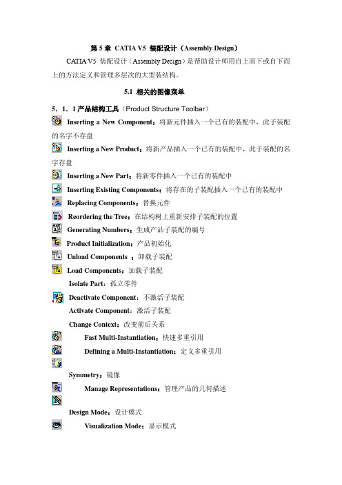
第5章CATIA V5 装配设计(Assembly Design)CATIA V5 装配设计(Assembly Design)是帮助设计师用自上而下或自下而上的方法定义和管理多层次的大型装结构。
5.1 相关的图像菜单5.1.1产品结构工具(Product Structure Toolbar)Inserting a New Component:将新元件插入一个已有的装配中,此子装配的名字不存盘Inserting a New Product:将新产品插入一个已有的装配中,此子装配的名字存盘Inserting a New Part:将新零件插入一个已有的装配中Inserting Existing Components:将存在的子装配插入一个已有的装配中Replacing Components:替换元件Reordering the Tree:在结构树上重新安排子装配的位置Generating Numbers:生成产品子装配的编号Product Initialization:产品初始化Unload Components :卸载子装配Load Components:加载子装配Isolate Part:孤立零件Deactivate Component:不激活子装配Activate Component:激活子装配Change Context:改变前后关系Fast Multi-Instantiation:快速多重引用Defining a Multi-Instantiation:定义多重引用Symmetry:镜像Manage Representations:管理产品的几何描述Design Mode:设计模式Visualization Mode:显示模式Deactivate a Node:不激活一个节点Activate a Node:激活一个节点Deactivate a Terminal Node:不激活一串节点Activate a Terminal Node:激活一串节点5.1.2 移动工具(Move Toolbar)Manipulating a Component:偏移或旋转子装配Snap Move:快速移动Smart Move:聪明移动Exploding an Assembly:爆炸图5.1.3 约束工具(Constraints Toolbar)Coincidence Constraint:同轴约束Contact Constraint:接触约束Offset Constraint:偏移约束Angle Constraint:角度约束Fixing a Component:固定一个子装配Fixing Components Together:子装配固定在一起Quick Constraint Command:快速约束命令Flexible Sub-Assemblies:柔性子装配Changing Constraints:改变约束Reuse Pattern:重复使用图样Deactivate Constraints:不激活约束Activate:激活约束5.1.4 更新工具(Update Toolbar)Update an Assembly:更新一个装配Update One Constraint Only:只更新约束5.1.5 约束创建模式工具(Constraint Creation Mode Toolbar)Default mode:默认模式Chain mode:链模式Stack mode:堆积模式5.1.6 注解工具(Annotations Toolbar)Text With Leader:带引出箭头的标注Flag Notes:超级链接5.1.7 装配特征工具(Assembly Features Toolbar)Assembly Split:装配切Assembly Hole:装配孔Assembly Pocket:装配凹坑Assembly Add:装配加Assembly Remove:装配减5.1.8 利用装配工具(Using Assembly Tools)Product Management:产品管理5.1.9分析工具(Analyze Tools)Bill of Material: 零件清单Analyze Updates:分析更新Analyze Constraints:分析约束Analyze Degrees of Freedom:分析自由度Analyze Dependences:分析依赖Compute Clash:计算干涉5.2 装配环境参数设定为了充分发挥CATIA V5的装配设计能力,必须根据设计对象的特点,合理地设定装配环境参数。
CATIA软件装配中的运动模拟教程

CATIA软件装配中的运动模拟教程CATIA(Computer-Aided Three-dimensional Interactive Application)是一款功能强大的三维建模软件,广泛应用于机械设计、装配与运动仿真等领域。
本教程将为您介绍CATIA软件在装配过程中的运动模拟功能,帮助您更好地理解和应用这一功能。
第一步:打开CATIA软件并创建装配文件在开始之前,首先确保您已经正确安装了CATIA软件。
打开软件后,选择“新建”,然后在弹出的对话框中选择“装配设计”。
第二步:导入零部件文件在装配过程中,我们需要导入零部件文件以进行后续的装配和运动模拟操作。
点击“导入”按钮,选择待导入的零部件文件,并将其添加到装配设计中。
第三步:创建关系在装配文件中,我们需要为不同零部件之间创建适当的关系,以确保它们按照预期方式进行运动。
选择“约束”工具,在零部件之间创建合适的约束关系,例如定位、配合等。
第四步:设置运动学属性在进行运动模拟之前,我们需要为每个零部件设置相应的运动学属性。
选择“属性”工具,为每个零部件设置正确的运动学类型,如旋转、平移等。
第五步:创建运动学关系运动学关系用于定义零部件之间的运动方式,将其连接起来形成一个整体模型。
选择“运动学”工具,在零部件之间创建适当的运动学关系,如齿轮、凸轮等。
第六步:设置运动规则在第五步中创建了运动学关系后,我们需要为整个装配定义运动规则。
选择“运动规则”工具,设置适当的约束和限制条件,以确保装配在运动模拟中的行为符合真实情况。
第七步:进行运动仿真完成以上准备工作后,我们可以开始进行运动仿真了。
选择“运动仿真”工具,在CATIA软件中模拟装配的运动过程,并观察各个零部件的运动轨迹、速度和加速度等参数。
第八步:分析运动仿真结果当运动仿真完成后,我们可以对仿真结果进行分析和评估。
CATIA 软件提供了丰富的可视化和数据分析工具,帮助我们深入了解装配过程中的运动性能和互动关系。
Catia装配设计入门
入门在草图编辑器和零件设计中生成零件后,现在您将学习如何在“装配设计(Assembly Design)”工作台中装配零件以完成设计。
在我们讨论装配工作台的详细使用说明之前,以下方案旨在让您对装配文档可以用来做什么有一个了解。
您只需按说明操作即可。
入门部分由以下任务组成:完成此方案需要大约15 分钟。
最后,装配如下所示:进入装配设计工作台并打开CATProduct 文档此任务(第一任务)说明如何进入“装配设计(Assembly Design)”工作台并打开现有产品。
1.选择“开始(Start)”->“机械设计(Mechanical Design)”->“装配设计(Assembly Design)”命令以启动所需的工作台。
工作台打开。
应用程序窗口右侧的工具栏中提供了用于装配零件的命令。
有关这些命令的信息,请参考“产品结构”文档。
您将注意到“Product1”显示在结构树中,指示要创建的装配的构造块。
要了解如何使用应用程序窗口边框中的“标准(Standard)”工具栏和“视图(View)”工具栏中提供的命令,请参考“基础结构”文档。
2.开始此方案之前,设置如下选项:确保已停用“使用高速缓存系统(Work with the cache system)”选项:使用“工具(Tools)”->“选项(Options)”命令,单击出现的对话框左侧的“基础结构(Infrastructure)”->“产品结构(Product Structure)”并取消选中选项“使用高速缓存系统(Work with the cache system)”。
关闭高速缓存后不要忘记重新启动应用程序。
有关更多信息,请参考使用高速缓存系统。
使用“工具(Tools)”->“选项(Options)”命令,单击出现的对话框左侧的“基础结构(Infrastructure)”->“产品结构 (P roduct Structure)”,然后单击“产品结构(Product Structure)”选项卡并取消选中“手动输入(Manual Input)”选项。
入门级-01-CATIA装配设计
目录
装配设计基础 装配操作 装配保存 干涉检查和其他
1
2 3
4
干涉检查和其他
装配中的干涉检查 检查干涉
四种干涉类型
打开文档Constraint.CATProduct
选到的产品 四种计算类型 距离范围
干涉检查和其他
干涉产品列表
结果浏览显示窗口 导出结果文件
干涉检查和其他
断面检查
打开文档Sectioning.CATProduct
H.
分解/固定子装配体
I. J. 更改约束
再使用模式 平行度 (Parallelism)(您需要定义面的方向。可以在“未定义
约束操作工具栏
E
A. B. C. 相合约束 联系约束 偏移约束
1
2
D.
E. F. G.
角度约束
固定组件 固定在一起 快速约束
在空间固定 (Fix in space) :使用指南针移动固定部 件,更新装配,固定部件返回到先前的位置。 固定:使用指南针移动固定部件,更新装配,固定部 件保持在新位置,相关部件移动到相应位置。
添加组件
组件可通过CATIA中的添加组件的命令,添加到产品中。以下类型的组件可添加到后 缀为 *.CATProduct 的CATIA产品中: • • • • • • *.CATPart *.CATProduct *.model *.igs *.cgr *.stp
产品结构工具栏
A
A.
B. C. D.
点击想要多实例化的组件
1
E. F.
2
3 4
产品结构工具栏
A. 图形树重新排序
B. C. D. 组件编号 选择性载入 管理表达
E
CATIA 英文教程
Questions and/or Comments email to: “cozzens@”
Southern Utah University, Cedar City, Utah
Step 2 Creating The Mounting
Figure 2.2
Questions and/or Comments email to: “cozzens@”
Click on the Mechanism Analysis icon.
Figure 2.9
.
.
Advanced CATIA V5 Workbook * * Schroff Development Corporation*
Step 8 Adding a Command
1. 2. 3. 4. 5. 6. 7. 8. 9.
Preparing The Assembly Creating The Mounting Assembling the U-Joint Into the Mounting Moving an Assembly Into The MU Kinematics Work Bench Automatic Joint Creation Manual Joint Creation Mechanism Analysis Adding a Command Editing A Simulation
Step 11 Compiling The Simulation
Click on the Compile Simulation icon.
Figure 2.15
Download site: Training AVI, PP Presentation, V5 models: /sdcpublications/pb-CATIA5.htm
CATIA软件装配设计教程
CATIA软件装配设计教程CATIA(Computer Aided Three-dimensional Interactive Application)是一种常用的三维CAD设计软件,广泛应用于机械、航空、汽车等领域。
本教程将介绍CATIA的装配设计功能及使用方法,帮助初学者快速上手。
一、CATIA软件简介CATIA是由法国达索系统公司开发的一款专业的三维CAD软件,可实现产品的设计、分析、装配和制造。
其强大的功能和广泛的应用使得CATIA成为工业设计师和工程师们首选的软件之一。
二、CATIA装配设计基础1. 新建装配文件在CATIA中,选择“文件”-“新建”-“产品”的方式新建装配文件。
2. 导入零部件将需要装配的零部件导入到装配文件中,点击工具栏上的“插入组件”按钮,选择要导入的零部件文件。
3. 定义装配关系使用CATIA的装配功能,可以将零部件精确地组合起来,并定义它们之间的关系。
通过选择零部件的表面或几何特性,设置装配关系,如配合、定位、约束等。
4. 约束设置在装配设计中,为了确保零部件的正确组装和运动,需要设置适当的约束。
常见的约束包括平行、垂直、对称、固定等。
5. 碰撞检测CATIA提供了碰撞检测功能,可以检测装配模型中是否存在碰撞或间隙。
通过该功能,可以有效避免设计中的错误和问题。
三、CATIA装配设计进阶1. 零部件可视化CATIA可以对装配模型进行可视化设置,通过调整显示属性、透明度等参数,使得装配模型更加直观清晰。
2. 装配分析CATIA提供了强大的装配分析功能,可以进行装配过程的运动仿真、应力分析等。
通过这些分析工具,可以评估装配的性能和可靠性。
3. 参数化设计利用CATIA的参数化设计功能,可以将装配模型中的尺寸、几何特性等参数化,方便进行多个版本的设计比较和修改。
4. 图纸生成在装配设计完成后,可以通过CATIA生成工程图纸。
CATIA提供了丰富的图纸模板和标准符号库,可以快速生成符合标准的图纸。
- 1、下载文档前请自行甄别文档内容的完整性,平台不提供额外的编辑、内容补充、找答案等附加服务。
- 2、"仅部分预览"的文档,不可在线预览部分如存在完整性等问题,可反馈申请退款(可完整预览的文档不适用该条件!)。
- 3、如文档侵犯您的权益,请联系客服反馈,我们会尽快为您处理(人工客服工作时间:9:00-18:30)。
Use Scene icon to create scene from the current state of the Assembly
When a scene already exists in the CATProduct , you can: - Copy and Paste it using Assembly Design Workbench - Edit it directly from Assembly Design Workbench by double clicking on it
1. Creating and Using Scenes Editing Scenes Applying Scenes to an Assembly Creating a Drafting View Based on a Scene Synchronyzing Scenes Deleting a Scene Generating Reports Bill of Material Reports Assembly Listing Reports Product Structure Numbering Generating Annotations Weld Planner Annotations Text Annotations Flag Note Positioning Components without Constraints Reasons for Positioning Components without Constraints Translating and Rotating using Snap Translating and Rotating using the Compass Positioning Components Using Smart Move 5 6 7 8 9 10 11 12 13 14 15 16 17 18 19 20 21 22 23
Here the assembly is set to the state as defined by the Partially Closed Scene Here the assembly is restored to its original state as defined by the Assembled Scene
Only selected node of the Scene and it’s child components will appear in the view.
Copyright DASSAULT SYSTEMES 2002
8
Synchronizing Scenes
In some cases Scenes are automatically synchronized with changes to an assembly. In other cases, manual intervention is required.
Bill of Material Reports Assembly Listing Reports Product Structure Numbering
Copyright DASSAULT SYSTEMES 2002
11
Bill of Material Reports
BOM with the components of the active assembly One BOM for each sub-assembly
List of components that will change when applying the scene
Copyright DASSAULT SYSTEMES 2002
7
Creating a Drafting View Based on a Scene
Scenes make it possible to have drafting views where components are in different states than the assembly.
New components are automatically added to Scenes, but they are inactivated Deleted components are automatically removed from Scenes
Moved components are automatically moved in Scenes if they were not repositioned in the Scene
CATIA Training
Foils for Instructor
Assembly Design Advanced
Version 5 Release 9 June 2002 EDU-CAT-E-ASM-AI-V5R9
Copyright DASSAULT SYSTEMES 2002
1
Table oAULT SYSTEMES 2002
5
Editing Scenes
Scenes enable capturing and restoring the state of components in an assembly. They are useful for creating assembly drawings and designing with the assembly in various states.
Copyright DASSAULT SYSTEMES 2002
13
Product Structure Numbering
Created Number
Created Number appearing in a balloon
Copyright DASSAULT SYSTEMES 2002
14
Generating Annotations
Recap of leaf components from the active assembly and all sub-assemblies
Interesting property of the component
Copyright DASSAULT SYSTEMES 2002
12
Assembly Listing Reports
2.
3.
4.
Copyright DASSAULT SYSTEMES 2002
2
Table of Contents (2/3)
5. Working with Large Assemblies Hiding Components Deactivating Representations Product Init Using Visualization Mode Differences between Modes Designing & Managing Contextual Parts Creating Contextual Parts Sketch and Design in Context Knowledgeware and Design in Context Editing Contextually-related Parts Analyzing Contextual Parts Isolating Contextual Parts Saving Contextually-related Documents Deleting Contextually-related Components Assembly Features What are Assembly Features Assembly Split Assembly Hole Assembly Pocket Adding a Body to an Assembly Removing a Body from an Assembly 24 25 26 27 28 29 30 31 32 33 34 36 37 38 39 40 41 42 43 44 45 46
Copyright DASSAULT SYSTEMES 2002
4
Creating and Using Scenes
You will learn how to create Scenes that capture various states of an assembly
Editing Scenes Applying Scenes to an Assembly Creating Drafting Views based on Scenes Synchronizing Scenes to an Assembly Deleting Scenes
You will learn how to generate three kind of annotations in 3D assemblies
Scenes can control:
- Hide state of components
- Color of Components - Position of components - Activation of representations Scenes are stored in an assembly’s CATProduct file
Copyright DASSAULT SYSTEMES 2002
6
Applying Scenes to an Assembly
It can be useful to design while having the assembly in various states. Scenes can be used to capture and restore the state of components in an assembly.
6.
7.
Copyright DASSAULT SYSTEMES 2002
