邦纳超声波传感器说明书(中文)
us-400s超声波纠偏传感器说明书
us-400s超声波纠偏传感器说明书
感谢您购买us-400s超声波纠偏传感器。
本说明书将介绍传感
器的安装、操作以及注意事项。
1. 产品概述:
us-400s超声波纠偏传感器是一款用于纠偏传输带的设备。
它采用超声波技术,可以测量传输带距离地面的高度,通过自动调整传输带的位置来纠正偏移。
2. 安装说明:
a. 选择传输带上适合的位置安装传感器。
确保传感器与传输
带之间没有任何障碍物。
b. 使用螺丝固定传感器在传输带上,确保传感器牢固地固定
在传输带上。
c. 将传感器的电缆连接到控制器或数据采集系统。
3. 操作说明:
a. 打开传感器的电源开关,并检查指示灯是否亮起。
b. 调整传输带的位置,使其与传感器保持良好的对齐。
传感
器将发射超声波信号并接收回波,从而测量距离。
c. 传感器会将测量得到的数据发送给控制器或数据采集系统,以便进行进一步的处理和纠偏操作。
4. 注意事项:
a. 在安装和操作传感器时,请确保传感器与其他设备保持适
当的安全距离。
b. 不要强行移动或扭曲传感器,以免损坏设备。
c. 定期清洁传感器表面,确保其正常工作。
d. 如有任何操作问题或故障,请立即停止使用传感器,并联系专业技术人员进行检修或维修。
希望以上说明对您的使用有所帮助。
如有其他问题,请随时与我们联系。
谢谢!。
超声波油位传感器产品手册

产品手册编制部门营销支撑部编制时间2013年3月20日抄送部门各分支机构、联盟运营商版本编号PS800V1.01、产品信息2.产品概况产品采用的是由国外引进的无接触式测量超声波传感器技术,广泛应用于检测位移、厚度、距离、液位、料位和透明物体,适用于测量液位介质、气体介质及容量。
3.产品介绍3.1、产品组成产品由一个超声波传感探头和一个信号控制盒两部分组成(如图一、图二所示)图一 图二 超声波传感探头 信号控制盒产品类别配件 产品类型 油位传感器 产品型号 XR6088-XDW-01 产品名称 超声波油位传感器产品代码192实物图3.2、技术参数工作电压:8-36V 50mA 工作温度:-40℃-80℃测量范围:3cm 到80cm (可定制更大量程) 承压范围:-0.1MPa~32MPa 液体高度精确:3mm液体测量精度:理论0.1L 实际约0.8L工作环境:防潮(探头)、防酸(探头)、抗干扰、防暴(探头)、阻燃(探头)、抗震(探头)探头防爆等级 : 本安 Exia Ⅱ CT6 隔爆 Exd Ⅱ CT5 防护等级 :IP66(探头)IP61(探头)设备接口:本设备提供电压模拟输出口、RS232数据口。
电压采样口:电压输出口输出的电压范围是 0.10—6.0V 。
实际液位与电压输出口的计算公式:1311.3*Vx+176单位为0.1mm 。
RS232串口:波特率默认为19200,每10S 传传感器实时测到的液位值(单位为0.1mm )、温度值(单位为0.1摄氏度)。
可以根据用户需要做波特率修改、传输数据的间隔时间。
超声波探头控制盒电源线探头延长线用户接口线接线:黄(接用户设备的RS232的TX线)、蓝(接用户设备的RS232的RX 线)、绿(接用户设备电压采样口)、黑(用户的设备地)。
3.3、特点3.3.1精度高,油位高度测量的分辨率为3mm,测量精度0.8L,同时传感器在-40℃到80℃间进行了温度校正,可以保证设备在高温及高寒的外部环境下,都可以保证较高的测量精度;3.3.2长期稳定性好,油位传感器采用超声波测量的方法,实行非接触式测量,区别于目前普遍采用的直接接触式的浮子式、压力式、磁制滑动式测量方法,从而避免油位传感器受到燃油的腐蚀和污染,可保持长期测量的稳定性;3.3.3易安装维护,只需将传感器安装油箱外部下方即可,无需改变原有的油箱测量系统,无需对油箱进行开孔和更改,并能保证原有汽车油表的正常运行;3.3.4环保无污染,耗能小,非接触式测量,无需对油箱打孔或改装而造燃油污垢及污染。
长距离超声波传感器数据手册说明书

DatasheetLong-range ultrasonic sensors with TEACH-mode programming•Fast, easy-to-use TEACH-Mode programming; no potentiometer adjustments •Scalable output automatically distributes the output signal over the width of the programmed sensing window•Minimum and Maximum window limits can be adjusted independently •Selectable 0 to 10 V dc or 4 to 20 mA output, selected via DIP switch•Access to bank of 8 DIP switches through sealed cover for superior user functionality •Rugged encapsulated design for harsh environments•Unique housing design allows for multiple mounting configurations•Choose models with integral unterminated 2 m (6.5 ft) or 9 m (30 ft) cable, or with Mini-style or M12/Euro-style quick-disconnect connection•Wide operating range of −20 °C to +70 °C (−4 °F to +158 °F)•Temperature compensation•Programmable for either positive or negative output slopeWARNING: Not To Be Used for Personnel ProtectionNever use this device as a sensing device for personnel protection. Doing so could lead to serious injury or death.This device does not include the self-checking redundant circuitry necessary to allow its use in personnel safety applications. A sensor failure or malfunction can cause either an energized or de-energized sensor output condition.Principles of OperationUltrasonic sensors emit one or multiple pulses of ultrasonic energy, which travel through the air at the speed of sound. A portion of this energy reflects off the target and travels back to the sensor. The sensor measures the total time required for the energy to reach the target and return to the sensor. The distance to the object is then calculated using the following formula: D = ct ÷ 2D = distance from the sensor to the target c = speed of sound in airt = transit time for the ultrasonic pulseTo improve accuracy, an ultrasonic sensor may average the results of several pulses before outputting a new value.TemperatureEffectsThe speed of sound is dependent upon the composition, pressure and temperature of the gas in which it is traveling. For most ultrasonic applications, the composition and pressure of the gas are relatively fixed, while the temperature may fluctuate.In air, the speed of sound varies with temperature according to the following approximation:In metric units:C m/s = 20 √273 + T C In English units:ft/s = 49 √460 + T F CC m/s = speed of sound in meters per second C ft/s = speed of sound in feet per second T C = temperature in °CT F = temperature in °F .suffix “w/30” to the model number of a cabled sensor (e.g., QT50ULB w/30). Models with a QD connector require a mating cable.U-GAGE ® QT50ULB Series Sensors with Analog OutputOriginal Document 70137 Rev. C27 July 201770137In metric units:C m/s = 20 √273 + T CIn English units:ft/s = 49 √460 + T F CC m/s = speed of sound in meters per second C ft/s = speed of sound in feet per second T C = temperature in °CT F = temperature in °FThe speed of sound changes roughly 1% per 6° C (10° F). QT50U series ultrasonic sensors have temperature compensation available, viathe 8-pin DIP switch. Temperature compensationwill reduce the error due to temperature by about 90%.Note: If the sensor is measuring across a temperature gradient, the compensation will be less effective.Analog Output SlopeThe U-GAGE QT50ULB Sensor may be programmed for either a positive or a negative output slope, depending on which conditions are taught for the Min and Max Analog limits. If the Min Analog limit is the Near Window setting and the Max Analog limit is the Far Window setting, then the slope will be positive. If the opposite is true, then the slope will be negative.Current-Sourcing ModelsTarget PositionPositive SlopeNear WindowFar WindowA n a l o g O u t p u t (m A )204Negative SlopeVoltage-Sourcing ModelsTarget PositionPositive SlopeNear WindowFar WindowV o l t a g e O u t p u t (V d c )100Negative SlopeFigure 1. Positive and Negative Output SlopsConfiguration - Tel: +1-763-544-3164P/N 70137 Rev. C* Factory default settingDIP Switch Selectable FunctionsCAUTION: To avoid damage to the sensor caused by static discharge (ESD), observe proper ESD precautions(grounding) while adjusting the DIP switches.Switch 1: Output Mode SelectON = 4 to 20 mA current output is enabledOFF = 0 to 10 V dc voltage output is enabledSwitch 1 configures the sensor internally to use either the current output or voltage output configuration.Switch 2: Loss of Echo Mode SelectON = Min-Max ModeOFF = Hold ModeSwitch 2 determines the output response to the loss of echo. “Min-Max Mode” (Switch 2 ON) drives the output to either the minimum value or the maximum value when the echo is lost. (Minimum or Maximum value is selected via Switch 3.)“Hold Mode” (Switch 2 OFF) maintains the output at the value which was present at the time of echo loss.Switch 3: Min-Max DefaultON = Default to maximum output value at loss of echo (10.5 V dc or 20.8 mA)OFF = Default to minimum output value at loss of echo (0 V dc or 3.6 mA)Switch 3 selects the output response to loss of echo when “Min-Max Mode” is selected via Switch 2. When Switch 2 is OFF, Switch 3 has no function.Switch 4: Teach/Transmit Enable ControlON = Gray (or yellow) wire configured for remote teachOFF = Gray (or yellow) wire configured for transmit enable/disable: High (5 to 30 V dc) - Transmit Enabled (Power LED solid Green);Low (0 to 2 V dc) - Transmit Disabled (Power LED flashes at 2 Hz)When Switch 4 is ON, the gray wire is used to teach window limits to the sensors.When Switch 4 is OFF, the gray wire is used to enable and disable the sensor’s transmit burst. The sensor output will react as if a “loss of echo” occurred and either hold the output or change to minimum or maximum value (depending on switch 2 and 3 settings). This function may be used when multiple sensors are in close proximity, which may make them vulnerable to crosstalk interference. A PLC can be used to enable the sensors one at a time to avoid crosstalk.Switches 5 and 6: Response Speed AdjustmentSwitches 5 and 6 are used to set the speed of the output response. The four values for response speed relate to the number of sensing cycles over which the output value is averaged.Switch 7: Temperature CompensationON = Temperature compensation enabledOFF = Temperature compensation disabledChanges in air temperature affect the speed of sound, which in turn affects the distance reading measured by the sensor. An increase in air temperature shifts both sensing window limits closer to the sensor. Conversely, a decrease in air temperature shifts both limits farther away from the sensor. This shift is approximately 3.5% of the limit distance for a 20 °C change in temperature. With temperature compensation enabled (Switch 7 ON), the sensor will maintain the window limits to within 1.8 percent over the –20 °C to 70 °C range. The temperature sensor in the sensor’s bezel cannot adapt to temperature change as quickly as an external temperature device can. When there are fast fluctuations in temperature, it may be best to use an external temperature monitor and feed its signal and the uncompensated distance measurement into a controller and perform the compensation calculations within the controller.P/N 70137 Rev. C - Tel: +1-763-544-31643Consult the factory for details on performing temperature compensation calculations.•If temperature compensation is enabled, exposure to direct sunlight can affect the sensor’s ability to accurately compensate for changes in temperature.•With temperature compensation enabled, the temperature warmup drift upon power-up is less than 0.8% of the sensing distance. After 15 minutes, the apparent distance will be within 0.5% of the actual distance. After 30 minutes, the apparent distance will be within 0.3% of the actual distance.Switch 8: Factory CalibrationON = Factory calibration onlyOFF = Normal operationFigure 4. Sensor Features MIN - Minimum limit indicatorMAX - Maximum limit indicator POWER - Sensor power indicator SIGNAL - Target signal strength indicatorGeneral Notes on Programming•The sensor returns to RUN mode if the limit is not registered within 120 seconds after entering TEACH Mode.•Press and hold the programming push button for more than 2 seconds (before teaching the limit) to exit PROGRAM mode without saving any changes. The sensor will revert to the last saved program.•If the push buttons do not respond, perform a remote lockout procedure to enable push buttons.Sensor ProgrammingTwo TEACH methods may be used to program the sensor:•Teach individual minimum and maximum limits•Use the Auto-Window feature to center a sensing window around the taught positionThe sensor may be programmed either via its two push buttons, or via a remote switch. Remote programming also may be used to disable the push buttons,preventing unauthorized personnel from adjusting the programming settings. To access this feature, connect the gray wire of the sensor to 0–2 V dc, with a remote programming switch between the sensor and the voltage.Note: The impedance of the Remote Teach input is 12 kΩ.Programming is accomplished by following the sequence of input pulses. The duration of each pulse (corresponding to a push button “click”), and the period between multiple pulses, are defined as “T” where 0.04 seconds < T < 0.8 seconds.Teaching Minimum and Maximum LimitsThe Min and Max Analog limits are independent. To readjust either limit, it is necessary to follow the teach procedure for that limit only. Setting the Minimum Analog Limit - Tel: +1-763-544-3164P/N 70137 Rev. CSetting the Maximum Analog LimitTeaching Limits Using the Auto-Window FeatureTeaches a sensing distance threshold centered within a fixed sensing window (a 1 m window centered on the position taught). This procedure centers the analog output on the taught position at approximately 5 V dc or 12 mA.Setting the Minimum Analog LimitSetting the Maximum Analog LimitP/N 70137 Rev. C - Tel: +1-763-544-31645Push Button LockoutThe Push Button Lockout feature enables or disables the keypad to prevent unauthorized personnel from adjusting the programming settings. This feature is not available using the buttons.Status IndicatorsMin Max MaxMinimum Operating RangeMinimum Analog SetpointMaximum Analog SetpointMaximum OperatingRangeTarget Within LimitsTarget Outside Min Limit Target Outside Sensing RangeTarget Outside Max LimitFigure 5. Status Indicator Conditions for Each Target Position - Tel: +1-763-544-3164P/N 70137 Rev. CWiringBanner recommends connecting the shield wire to earth ground or dc common.P/N 70137 Rev. C - Tel: +1-763-544-31647DimensionsSpecificationsSupply Voltage and Current10 to 30 V dc (10% maximum ripple)100 mA max at 10 V, 40 mA max at 30 V (exclusive of load)Sensing Range200 mm to 8 m (8 inches to 26 feet)Ultrasonic Frequency75 kHz burst, rep. rate 96 msSupply Protection CircuitryProtected against reverse polarity and transient overvoltages Output ProtectionProtected against short circuit conditions Delay at Power-up1.5 secondsAnalog Output Configuration (Voltage Sourcing: 0 to 10 V dc)Minimum Load Resistance = 500 ohmsMinimum Required Supply Voltage for Full 0-10 V Output Span = (1000/RLoad + 13) V dc Analog Output Configuration (Current Sourcing: 4 to 20 mA)Maximum Load Resistance = 1 k Ω or ( Vsupply/0.02 - 5) ohms, whichever is lowerMinimum required supply voltage for full 4-20 mA output span = 10 V dc or [(RLoad × 0.02) + 5] V dc, whichever is greater.4 to 20 mA output calibrated at 25 °C with a 250 Ω load.Temperature EffectUncompensated: 0.2% of distance/°C Compensated: 0.02% of distance/°CLinearity+/- 0.2% of span from 200 to 8000 mm+/- 0.1% of span from 500 to 8000 mm (1 mm minimum)Resolution1.0 mmOutput Response Time100 ms to 2300 msSee DIP Switches 5 and 6Minimum Window Size20 mmAdjustmentsSensing window limits: TEACH-Mode programming of near and far window limits may be set using the push buttons or remotely via TEACH input.IndicatorsGreen Power On LED: Indicates power is ONRed Signal LED: Indicates target is within sensing range, and the condition of the received signalTeach/Output indicator (bicolor Amber/Red): Amber – Target is within taught limits; Flashing Amber – Target is outside taught window limits; Red – Sensor is in TEACH mode Remote TEACHTo Teach: Connect gray or yellow wire to 0 to 2 V dc; impedance 12 k ΩConstructionTransducer: Ceramic/Epoxy composite Housing: ABS/Polycarbonate Membrane Switch: Polyester Lightpipes: Acrylic Operating ConditionsTemperature: –20 °C to 70 °C (–4 °F to 158 °F)Maximum relative humidity: 100%Connections2 m (6.5 ft) or 9 m (30 ft) shielded 5-conductor (with drain) PVC jacketed attached cable or 5-pin Euro-style quick-disconnect or 5-pin Mini-style quick-disconnect Environmental RatingLeakproof design is rated IEC IP67; NEMA 6PVibration and Mechanical ShockAll models meet Mil Std. 202F requirements. Method 201A (vibration: 10 to 60Hz max., double amplitude 0.06", maximum acceleration 10G). Also meets IEC 947-5-2 requirements: 30G 11 ms duration, half sine wave Temperature Warmup DriftLess than 0.8% of sensing distance upon power-up with Temperature Compensation enabled (see Temperature Compensation)Application NotesObjects passing inside the specified near limit (200 mm) may produce a false response.Certifications - Tel: +1-763-544-3164P/N 70137 Rev. CPerformance CurvesE f f e c t i v e B e a m W i d t hTarget Distance1 m (3.3')2 m (6.6')3 m (9.8')4 m (13.1')5 m (16.4')6 m (19.6')7 m (22.9')8 m (26.2')8"-8"016"-16"24"-24"31"-31"-40"40"-10-20-30100203040-400Target Distance (m)T a r g e t R o t a t i o n (d e g )1 m (3.3’)2 m (6.6’)3 m (9.8’)4 m (13.1’)5 m (16.4’)6 m (19.6’)7 m (22.9’)8 m (26.2’)AccessoriesCordsetsP/N 70137 Rev. C - Tel: +1-763-544-31649BracketsBanner Engineering Corp Limited WarrantyBanner Engineering Corp. warrants its products to be free from defects in material and workmanship for one year following the date of shipment. Banner Engineering Corp. will repair or replace, free of charge, any product of its manufacture which, at the time it is returned to the factory, is found to have been defective during the warranty period. This warranty does not cover damage or liability for misuse, abuse, or the improper application or installation of the Banner product.THIS LIMITED WARRANTY IS EXCLUSIVE AND IN LIEU OF ALL OTHER WARRANTIES WHETHER EXPRESS OR IMPLIED (INCLUDING, WITHOUT LIMITATION, ANY WARRANTY OF MERCHANTABILITY OR FITNESS FOR A PARTICULAR PURPOSE), AND WHETHER ARISING UNDER COURSE OF PERFORMANCE, COURSE OF DEALING OR TRADE USAGE. - Tel: +1-763-544-3164P/N 70137 Rev. CU-GAGE® QT50ULB Series Sensors with Analog Output This Warranty is exclusive and limited to repair or, at the discretion of Banner Engineering Corp., replacement. IN NO EVENT SHALL BANNER ENGINEERING CORP. BE LIABLE TO BUYER OR ANY OTHER PERSON OR ENTITY FOR ANY EXTRA COSTS, EXPENSES, LOSSES, LOSS OF PROFITS, OR ANY INCIDENTAL, CONSEQUENTIAL OR SPECIAL DAMAGES RESULTING FROM ANY PRODUCT DEFECT OR FROM THE USE OR INABILITY TO USE THE PRODUCT, WHETHER ARISING IN CONTRACT OR WARRANTY, STATUTE, TORT, STRICT LIABILITY, NEGLIGENCE, OR OTHERWISE.Banner Engineering Corp. reserves the right to change, modify or improve the design of the product without assuming any obligations or liabilities relating to any product previously manufactured by Banner Engineering Corp. Any misuse, abuse, or improper application or installation of this product or use of the product for personal protection applications when the product is identified as not intended for such purposes will void the product warranty. Any modifications to this product without prior express approval by Banner Engineering Corp will void the product warranties. All specifications published in this document are subject to change; Banner reserves the right to modify product specifications or update documentation at any time.Specifications and product information in English supersede that which is provided in any other language. For the most recent version of any documentation, refer to: .© Banner Engineering Corp. All rights reserved。
247able EchoMax XPS-10超声波传感器说明书

Supplied byCall us on +44 (0)118 916 9420 | Email ****************.comDatasheetECHOMAX XPS-10 ULTRASONIC TRANSDUCER4/181Siemens FI 01 · 2016Level MeasurementContinuous level measurement - Ultrasonic transducers4■Overview EchoMax XPS transducers use ultrasonic technology to measure level in a wide range of liquids and solids.■Benefits•Integral temperature compensation•Low ringing effect reduces blanking distance •Optional foam facing for dusty applications •Self-cleaning and low-maintenance •Chemically resistant •Hermetically sealed■ApplicationXPS transducers can be fully immersed, are resistant to steam and corrosive chemicals, and can be installed without flanges.The XPS series offers versions for various measuring ranges up to 30 m (100 ft) and up to a max. temperature of 95 °C (203 °F).During operation, the EchoMax transducers emit acousticpulses in a narrow beam. The level monitor measures the prop-agation time between pulse emission and its reflection (echo) tocalculate the distance.Siemens FI 01 · 2016Level MeasurementContinuous level measurement - Ultrasonic transducers4■Technical specifications1)EMC certificate available on request.InputXPS-10XPS-15 (standard and F models) XPS-30Measuring range0.3 ... 10 m (1 ... 33 ft)Standard:0.3... 15 m (1 ... 50 ft) XPS-15F:0.45... 15 m (1.5 ... 50 ft)0.6 ... 30 m (2 ... 100 ft)Output Frequency 44 kHz 44 kHz 30 kHz Beam angle 12°6°6°Environmental LocationIndoors/outdoorsAmbient temperature-40...+95 °C (-40...+203°F)Standard:-40 ... +95 °C (-40 ... +203 °F)XPS-15F:-20...+95°C (-4...+203°F)-40...+95 °C (-40...+203°F)Pollution degree 4Pressure8 bar g (120psi g)Flanged:0.5 bar g (7.25 psi g)8 bar g (120psi g)Flanged:0.5 bar g (7.25 psi g)0.5 bar g (7.25 psi g)Flanged:0.5 bar g (7.25 psi g)Design Weight0.8 kg (1.8 lb)1.3 kg (2.8 lb)Flanged:2 kg (4.4 lb) 4.3 kg (9.5 lb)Power supply Operation of transducer only with approved Siemens controllers MaterialStandard: PVDFFlanged: PVDF with CPVC flange Option: PTFE face with CPVC flangeStandard: PVDFFlanged: PVDF with CPVC flange Option: PTFE face with CPVC flange Standard: PVDFFlanged: PVDF with CPVC flange Option: PTFE face with CPVC flange Color BlueStandard: Blue XPS-15F: GrayBlueProcess connection 1" NPT or 1" BSPT Standard: 1" NPT or 1" BSPT XPS-15F: 1" NPT 1.5" universal thread (NPT or BSPT)Degree of protection IP66/68IP66/68IP66/68Cable 2-wire twisted pair/braided and foil shielded 0.5 mm² (20 AWG) PVC jacket SeparationMax. 365 m (1200 ft) Certificates and approvalsStandard:CE, CSA, FM, ATEX, IECExStandard:CE, CSA, FM, ATEX, IECEx XPS-15F:FM Class I, Div. 1, Groups A, B, C, and D, Class II, Div. 1, Groups E, F , and G, Class IIICE, CSA, FM, ATEX, IECEx4/183Siemens FI 01 · 2016Level MeasurementContinuous level measurement - Ultrasonic transducers4We can offer shorter delivery times for configurations designated with the Quick Ship Symbol . For details see page 9/5 in the appendix.1)Not available with flanged versions 2)Available with flanged versions only 3)Valid with mounting thread and facing options 0 ... 2 onlySelection and Ordering dataOrder codeFurther designsPlease add "-Z " to Article No. and specify Order code(s).Stainless steel tag [69 x 50 mm (2.71 x 1.97inch)]: Measuring point number/ identification (max.27characters) specify in plain text Y15Operating InstructionsArticle No.Quick Start guide, multi-language A5E32282889Applications Guidelines, multi-language7ML1998-5HV61Note: The Operating Instructions should be ordered as a separate line item on the order.All literature is available to download for free, in a range of languages, at /processinstrumentation/documentationThis device is shipped with the Siemens Level and Weighing manual DVD containing the ATEX Quick Start and Operating Instructions library.AccessoriesTag, stainless steel with hole, 12 x 45 mm(0.47x 1.77inch), one text line for fastening on sensors7ML1930-1BJSubmergence shield kit7ML1830-1BH Easy Aimer 2, aluminum, NPT with ¾" x 1" PVC coupling7ML1830-1AQ Easy Aimer 2, aluminum with M20 adapter and 1" and 1½" BSPT aluminum couplings 7ML1830-1AX Easy Aimer 304, NPT with 1" stainless steel coupling7ML1830-1AU Easy Aimer 304, with M20 adapter and 1" and 1½"BSPT 304 stainless steel couplings 7ML1830-1GN Universal box bracket, mounting kit 7ML1830-1BK Channel bracket, wall mount7ML1830-1BL Extended channel bracket, wall mount 7ML1830-1BM Channel bracket, floor mount7ML1830-1BN Extended channel bracket, floor mount 7ML1830-1BP Bridge channel bracket, floor mount(see Mounting Brackets on page 4/190 for more information)7ML1830-1BQ1"NPT locknut, plastic 7ML1830-1DS 1" BSPT locknut, plastic7ML1830-1DR4/184Siemens FI 01 · 2016Level MeasurementContinuous level measurement - Ultrasonic transducers4We can offer shorter delivery times for configurations designated with the Quick Ship Symbol . For details see page 9/5 in the appendix.We can offer shorter delivery times for configurations designated with the Quick Ship Symbol. For details see page 9/5 in the appendix.1)Not available with flanged versions 2)Available with flanged versions only3)Available with mounting options 0 ... 2 onlySelection and Ordering dataOrder codeFurther designsPlease add "-Z " to Article No. and specify Order code(s).Stainless steel tag [69 x 50 mm (2.71 x 1.97inch)]: Measuring point number/ identification (max.27characters) specify in plain text Y15Operating InstructionsArticle No.Quick Start guide, multi-language A5E32282889Applications Guidelines, multi-language7ML1998-5HV61Note: The Operating Instructions should be ordered as a separate line item on the order.All literature is available to download for free, in a range of languages, at /processinstrumentation/documentationThis device is shipped with the Siemens Level and Weighing manual DVD containing the ATEX Quick Start and Operating Instructions library.AccessoriesTag, stainless steel with hole, 12 x 45 mm(0.47x 1.77inch), one text line for fastening on sensors7ML1930-1BJSubmergence shield kit7ML1830-1BJ Universal box bracket, mounting kit 7ML1830-1BK Channel bracket, wall mount7ML1830-1BL Extended channel bracket, wall mount 7ML1830-1BM Channel bracket, floor mount7ML1830-1BN Extended channel bracket, floor mount 7ML1830-1BP Bridge channel bracket, floor mount(see Mounting Brackets on page 4/190 for more information)7ML1830-1BQ1"NPT locknut, plastic 7ML1830-1DS 1" BSPT locknut, plastic7ML1830-1DR Easy Aimer 2, aluminum, NPT with ¾" x 1" PVC coupling7ML1830-1AQ Easy Aimer 2, aluminum with M20 adapter and 1" and 1½" BSPT aluminum couplings 7ML1830-1AX Easy Aimer 304, NPT with 1" stainless steel coupling7ML1830-1AU Easy Aimer 304, with M20 adapter and 1" and 1½" BSPT 304 stainless steel couplings7ML1830-1GNLevel Measurement Continuous level measurement - Ultrasonic transducers44/185Siemens FI 01 · 20164/186Siemens FI 01 · 2016Level MeasurementContinuous level measurement - Ultrasonic transducers41)Not available with flanged version 2)Available for flanged versions onlySelection and Ordering dataOrder codeFurther designsPlease add "-Z " to Article No. and specify Order code(s).Stainless steel tag [69 mm x 50 mm(2.71x 1.97inch)]: Measuring-point number /identification (max. 27 characters) specify in plain textY15Operating InstructionsArticle No.Quick Start guide, multi-language A5E32282889Applications Guidelines, multi-language7ML1998-5HV61Note: The Operating Instructions should be ordered as a separate line item on the order.All literature is available to download for free, in a range of languages, at /processinstrumentation/documentationThis device is shipped with the Siemens Level and Weighing manual DVD containing the ATEX Quick Start and Operating Instructions library.AccessoriesEasy Aimer 2, aluminum, NPT with 1½" galvanized coupling7ML1830-1AN Easy Aimer 304, NPT with 1½" stainless steel coupling7ML1830-1AT 1½" BSPT locknut, plastic7ML1830-1DP4/187Siemens FI 01 · 2016Level MeasurementContinuous level measurement - Ultrasonic transducers4■Dimensional drawingsXPS ultrasonic transducer■SchematicsXPS ultrasonic transducer connectionsVersion Dimension XPS-10XPS-15XPS-30A 88 mm(3.464inch)121 mm (4.764inch)175 mm (6.890inch)B 122 mm (4.803inch)132 mm (5.197inch)198 mm (7.795inch)C According to ASME, DIN, and JISE 124 mm (4.882inch)158 mm (6.220inch)n/aF 152 mm (5.984inch)198 mm (7.795inch)n/aJ28 mm (1.1inch)28 mm (1.1inch)28 mm (1.1inch)。
超声波传感器技术指南

功能。 ● 若未充分固定,则会因振动等引起破损,或因移动而无
法进行正确检测。 关于环境 ● 为了维持动作的可靠性和长寿命,请避免在超过额定的
温度和外部空气条件下(室外)进行使用。 ● 由于超声波式传感器将空气作为传播媒介,所以若局部
超声波传感器 技术指南
术语解说
送波 是指在发振侧连接振子,向指定方向发射的超声波,通常 用施加在振子上的电压值或声压来表示。
受波 是指直接接受发送来的超声波,或在振子位置接受物体发 出的反射波,通常用转换后的电压值或声压表示。
余响 若在振子上,以脉冲形式施加了接近其共振频率的电气信 号,则即使电气信号消失,超声波振动也会机械性的持续 短时间的现象称为余响。在反射型中,这种余响现象若持 续长时间,则无法检测。
光电传感器 接近传感器 位移传感器 超声波传感器
θ
限定区域(反射型) 在检测距离的调整中,不仅是最大检测距离,对最小检测 距离也能连动或单独调整,该可检测范围称为限定区域 (区域限定)。
不感应区与不确定区域(反射型) 检测距离调整的结果,传感器探头面和最小检测距离间无 法检测的区域称为不感应区,因传感器探头的结构及余响 振动,在探头附近无法检测的区域称为不确定区域。 但在不确定区域中,有时可通过传感器与物体间的多重反 射进行检测。
原理
在超声波的发信/受信中使用了压电陶瓷。
压电陶瓷的定义 由于施加在元件上的机械力,在电极间随着力而产生了电动势。此外,与此相反,若在电极间施加了电压,随着其大小 则会产生机械性位移。 通过这种电动势的大小,来检测、计量对象物的有无和传感器到对象物之间的距离。
超音波传感器数据手册说明书

DatasheetUltrasonic Sensors with TEACH-Mode Programming•Fast, easy-to-use TEACH-Mode programming; no potentiometer adjustments•Choose to set a specific window size and position, or a set point centered within its own10 mm window, for either or both outputs•Program both outputs together or independently. The two outputs may be identical,independent, overlapping, or complementary•Remote TEACH for security and convenience•Choose models with 150 mm to 1 m range (5.9 in to 39.4 in) or 300 mm to 2 m range(11.8 in to 78.7 in)•Wide operating range of –20 °C to +70 °C (–4 °F to +158 °F)•Choose models with either NPN or PNP dual discrete outputs•LED indicators for Power ON/OFF, Signal Strength, and Discrete Outputs Conducting•Choose models with integral unterminated 2 m (6.5 ft) or 9 m (30 ft) cable, or with M12/Euro-style quick-disconnect connection•Compact, self-contained sensor package•Rugged design for use in demanding sensing environments; rated IEC IP67, NEMA 6PWARNING:•Do not use this device for personnel protection•Using this device for personnel protection could result in serious injury or death.•This device does not include the self-checking redundant circuitry necessary to allow its use inpersonnel safety applications. A device failure or malfunction can cause either an energized (on) or de-energized (off) output condition.ModelsOverviewThe U-GAGE is an easy-to-use ultrasonic sensor, ideal for demanding environments. Simple push-button programming provides flexibility for a variety of applications. Excellent for gauging applications such as sensing of liquid levels in a tank or for sensing most clear materials.Each sensor includes two discrete outputs, which may be programmed independently with different window limits or together with identical limits. Each output has the option of being set with a sensing distance set point centered within a 10 mm window.W/30 to the model number of any cabled sensor (for example, T30UDNA W/30). A model with a QD connector requires an optional mating cable; see Cordsets (p. 7).U-GAGE® T30 Series with Dual Discrete OutputsOriginal Document59200 Rev. F25 October 201959200Configuration InstructionsSensor ProgrammingWindow limits may be taught to the sensor in several ways. The following methods describe the programming procedures using the push buttons on the back of the sensor; remote programming (remote TEACH) procedures are described in Remote Programming (p. 3).Note: When the sensor changes state between Program and Run modes, all of the LED indicators turn OFFmomentarily, before the appropriate LEDs turn ON as described below. The sensing window limits expandtemporarily to full scale (max range) during Program mode.Output 1Programming Push ButtonFigure 1. U-GAGE T30 Series sensor programming push buttons and indicatorsProgram the outputs independently to define separate sensing windows (both their size and placement) or program the outputs simultaneously for complementary or fixed field operation.Sensing windows may be as large as 0.85 m for 1 m range models, and as large as 1.7 m for 2 m range models. Use the procedures as described, or combine them for specialized applications.Note: Output 1 = White wire, Output 2 = Black wireGeneral Notes on Programming:1.The sensor returns to Run mode if the first TEACH condition is not registered within 120 seconds.2.After the first limit is taught, the sensor remains in Program mode until the TEACH sequence is finished.3.Press and hold the programming push button > 2 seconds (before teaching the second limit) to exit Program mode withoutsaving any changes. The sensor will revert to the last saved program.4.The sensor allows for some forgiveness in the teaching of a set point. If both near and far limits are not exactly the same(but are closer than the minimum 10 mm required to define a window), the sensor will set a 10 mm window with the center at the “average” of the two limits.2Separate Sensing Window LimitsDeadZoneFigure 2. Programming separate sensing window limitsEach output conducts when the target is inside that output’s window limits.The two sets of window limits may overlap or be completely independent.1. Press and hold the push button for the selected output until the greenPower LED turns OFF and the yellow LED for the programmed outputturns ON.2. Position the target at the first limit and click the push button. Theyellow Output LED flashes.3. Position the target at the second limit and click the push button. Thegreen Power LED turns ON. The sensor is in Run mode.4. Repeat the procedure for the second output, if desired. - Tel: + 1 888 373 6767P/N 59200 Rev. FSeparate Sensing Set Point LimitsDeadZoneFigure 3. Programming separate sensing set point limitsEach output conducts when the target is inside that output’s 10 mm limits(centered on the taught set point, or the average of the two limits). Thewindow limits for the two outputs may overlap or be completelyindependent.1. Press and hold the push button for the selected output until the greenPower LED turns OFF and the yellow LED for the programmed outputturns ON.2. Position the target at the set point and click the push button. Theyellow Output LED flashes.3. While the target remains at the first limit (or within 10 mm), click thepush button once more. The green Power LED turns ON. The sensor isin Run mode.4. Repeat the procedure for the second output, if desired.DeadZoneFigure 4. Programming a single pair of sensing window limits,complementary outputsOutput 2 conducts when inside the programmed window limits; Output 1conducts for all other conditions.1. Press and hold both push buttons (or press and hold one and thenthe other) until the green Power LED turns OFF and both yellow OutputLEDs turn ON.2. Position the target at the first limit and click a push button. Theyellow Output LED flashes.3. Position the target at the second limit and click a push button. Thegreen Power LED turns ON. The sensor is in Run mode.Note: The window limits must be ≥ 10 mm or thesensor will default to fixed-field style.DeadZoneFigure 5. Programming separate sensing set point limits,complementary outputsOutput 2 conducts when inside the programmed set point; Output 1conducts outside (away) from this point.1. Press and hold both push buttons (or press and hold one and thenthe other) until the green Power LED turns OFF and both yellow OutputLEDs turn ON.2. Position the target at the first limit and click a push button. Theyellow Output LED flashes.3. While the target remains at the first limit (or within 10 mm), click thepush button once more. The green Power LED turns ON. The sensor isin Run mode.Remote ProgrammingUse the Remote Programming function to program the sensor remotely or to disable the keypad, Disabling the keypad prevents anyone from adjusting any of the programming settings directly from the sensor. Connect the gray wire of the sensor to +12 to 24V dc, with a remote programming switch connected between them.Note: The impedance of the remote teach input is 55 kΩ.Follow the sequence of input pulses to program the sensor. The duration of each pulse (corresponding to a push button “click”), and the period between multiple pulses, is defined as: 0.04 seconds < T < 0.8 seconds.• 1 pulse: Programs first Output 2 limit. Wait > 0.8 seconds. Next pulse programs second Output 2 limit.• 2 pulses: Programs first Output 1 limit. Wait > 0.8 seconds. Next pulse programs second Output 1 limit.• 3 pulses: Programs both outputs together (complementary or fixed-field mode). First 3-pulse programs the first limit; wait >0.8 sec. Next pulse programs second limit and determines output configuration.• 4 pulses: Disables (locks out) or enables the keypad for security.P/N 59200 Rev. F - Tel: + 1 888 373 67673LimitOutput 2 Limits OnlyLimitLimitPush Button Locked out(or Enabled)Output 1Limits OnlyLimit Both OutputsTogetherPush ButtonLockout (or Enable)0.04 sec < T < 0.8 secFigure 6. Timing programs for remote TEACH programmingNote: Hold the Remote line high > 2 seconds (before teaching the second limit) to exit Program mode without saving any changes. The sensor will revert to the last saved program.Wiring Diagrams–Figure 7. Cabled NPNFigure 8. Cabled PNP5-pin M12/Euro-style male connector models Key 1 = Brown2 = White3 = Blue4 = Black5 = GrayIt is recommended that the shield wire is connected to earth ground or dc common.Run ModeNote: All LED indicators momentarily turn OFF when the sensor changes state between Program and Run modes.Signal LEDThe red Signal LED indicates the strength and condition of the sensor’s incoming signal.Output LEDs4 - Tel: + 1 888 373 6767P/N 59200 Rev. FEach amber Output LED lights when a target is sensed within the programmed window limits.Power ON/OFF LEDThe green Power ON/OFF LED indicates the operating status of the sensor.Self-Diagnostic Error ModeIn the unlikely event of a microprocessor memory error, all of the LEDs will flash in sequence. If this occurs, the setup parameters have been lost and the sensor may be corrupt. Contact Banner Engineering for further information.SpecificationsProximity Mode Range“A” suffix models: 150 mm (5.9 in) min. near limit; 1 m (39 in) max. far limit “B” suffix models: 300 mm (11.8 in) min. near limit; 2 m (79 in) max. far limit Supply Voltage12 to 24 V dc (10% max. ripple) at 90 mA, exclusive of loadSupply Protection CircuitryProtected against reverse polarity and transient voltagesOutput ConfigurationsSPST solid-state switch; choose NPN (current sinking) or PNP (currentsourcing) modelsOutput RatingsDual Discrete Outputs: 100 mA maximum, total – both outputsOFF-state leakage current: less than 10 microampsON-state saturation voltage: less than 1 V at 10 mA and less than 1.5 V at 100 mAOutput ProtectionProtected against continuous overload and short-circuit; transient over-voltage; no false pulse on power-upOutput Response Time“A” suffix models: 48 milliseconds“B” suffix models: 96 millisecondsSensing PerformanceSensing repeatability: ±0.25% of distanceMinimum window size: 10 mm (0.4 in)Hysteresis of discrete output: 2.5 mm (0.10 in)AdjustmentsSensing window limits: TEACH-mode programming of near and far window limits may be set using membrane push buttons on sensor or remotely via TEACH input. Window limits may be programmed separately, or together ConstructionMolded reinforced thermoplastic polyester housingEnvironmental RatingLeakproof design is rated IEC IP67, NEMA 6PConnections2 m (6.5 ft) or 9 m (30 ft) 5-conductor PVC-covered attached cable, or 5-pinEuro-style quick-disconnect fittingOperating ConditionsTemperature: –20 °C to +70 °C (–4 °F to +158 °F)Humidity: 100% maximum relative humidityVibration and Mechanical ShockAll models meet Mil. Std. 202F requirements. Method 201A (Vibration: 10 to60 Hz max., double amplitude 0.06 in, maximum acceleration 10G). Alsomeets IEC 947-5-2 requirements: 30G, 11 ms duration, half sine wave CertificationsApplication NotesObjects passing inside the specified near limit will produce a false responseIndicatorsP/N 59200 Rev. F - Tel: + 1 888 373 67675Performance Curves00200 mm (8.0 in)400 mm (16.0 in)600 mm (24.0 in)800 mm (32.0 in)1000 mm (40.0 in)50501001001501502002002.0 in 2.0 in 4.0 in4.0 in 6.0 in 6.0 in8.0 in 8.0 in DISTANCEW I D T H (m m )Figure 9. A Models00400 mm (16.0 in)800 mm (32.0 in)1200 mm (48.0 in)1600 mm (64.0 in)2000 mm (80.0 in)10010020020030030040040004.0 in 4.0 in 8.0 in 8.0 in 12.0 in 12.0 in16.0 in 16.0 inDISTANCE WI D T H (m m )Figure 10. B Models05050100100150150200200200 mm (8.0 in)400 mm (16.0 in)600 mm (24.0 in)800 mm (32.0 in)1000 mm (40.0 in)2.0 in 2.0 in 4.0 in4.0 in 6.0 in 6.0 in8.0 in 8.0 in DISTANCE W I D T H (m m )Figure 11. A Models010*******200300300400400DISTANCE 0400 mm (16.0 in)800 mm (32.0 in)1200 mm (48.0 in)1600 mm (64.0 in)2000 mm (80.0 in)04.0 in 4.0 in 8.0 in 8.0 in 12.0 in12.0 in16.0 in 16.0 inW I D T H (m m )Figure 12. B ModelsDimensionsM30 x 1.5ThreadQuick-Disconnect Models - Tel: + 1 888 373 6767P/N 59200 Rev. FAccessoriesCordsetsBracketsAll measurements are in mm.P/N 59200 Rev. F - Tel: + 1 888 373 67677Banner Engineering Corp. Limited WarrantyBanner Engineering Corp. warrants its products to be free from defects in material and workmanship for one year following the date of shipment. Banner Engineering Corp. will repair or replace, free of charge, any product of its manufacture which, at the time it is returned to the factory, is found to have been defective during the warranty period. This warranty does not cover damage or liability for misuse, abuse, or the improper application or installation of the Banner product.THIS LIMITED WARRANTY IS EXCLUSIVE AND IN LIEU OF ALL OTHER WARRANTIES WHETHER EXPRESS OR IMPLIED (INCLUDING, WITHOUT LIMITATION, ANY WARRANTY OF MERCHANTABILITY OR FITNESS FOR A PARTICULAR PURPOSE), AND WHETHER ARISING UNDER COURSE OF PERFORMANCE, COURSE OF DEALING OR TRADE USAGE. This Warranty is exclusive and limited to repair or, at the discretion of Banner Engineering Corp., replacement. IN NO EVENT SHALL BANNER ENGINEERING CORP. BE LIABLE TO BUYER OR ANY OTHER PERSON OR ENTITY FOR ANY EXTRA COSTS, EXPENSES, LOSSES, LOSS OF PROFITS, OR ANY INCIDENTAL, CONSEQUENTIAL OR SPECIAL DAMAGES RESULTING FROM ANY PRODUCT DEFECT OR FROM THE USE OR INABILITY TO USE THE PRODUCT, WHETHER ARISING IN CONTRACT OR WARRANTY, STATUTE, TORT, STRICT LIABILITY, NEGLIGENCE, OR OTHERWISE.Banner Engineering Corp. reserves the right to change, modify or improve the design of the product without assuming any obligations or liabilities relating to any product previously manufactured by Banner Engineering Corp. Any misuse, abuse, or improper application or installation of this product or use of the product for personal protection applications when the product is identified as not intended for such purposes will void the product warranty. Any modifications to this product without prior express approval by Banner Engineering Corp will void the product warranties. All specifications published in this document are subject to change; Banner reserves the right to modify product specifications or update documentation at any time. Specifications and product information in English supersede that which is provided in any other language. For the most recent version of any documentation, refer to: .For patent information, see /patents.© Banner Engineering Corp. All rights reserved。
TCT40-16T3 16R3 超声波传感器 说明书

概述避障电路图超声波发射装置由NE555构成无稳多谐振荡器,其振荡频率由电阻W1、R1和C3决定通过调节W1可以改变振荡频率,输出的振荡信号经过CD4049的放大推动超声波换能器S1发声。
NE555的第4脚使能端可由单片机控制,当需要发射超声信号时该脚为高电平。
超声波接收装置超声波换能器S1接受到的微弱信号,经过交流耦合到IC1放大,其放大倍数为:A1=-R6/R4=-50;放大的信号在经过交流耦合到IC1的另一运放,其放大倍数为:A2=-R9/R7=-20;总增益为:A=A1*A2=1000。
经过放大的信号再由比较器LM311整形,输出标注TTL电平信号以被单片机接收。
测距电路I测距原理:超声波发射器向某一方向发射超声波,在发射时刻的同时开始计时,超声波在空气中传播,途中碰到障碍物就立即返回来,超声波接收器收到反射波就立即停止计时。
超声波在空气中的传播速度为340m/s,根据计时器记录的时间t,就可以计算出发射点距障碍物的距离(s),即:s=340t/21) 40kHz 脉冲的产生与超声波发射测距系统中的超声波传感器采用UCM40的压电陶瓷传感器,它的工作电压是40kHz的脉冲信号。
测距电路的输入端接单片机P1.0端口,单片机执行下面的程序后,在P1.0 端口输出一个40kHz的脉冲信号,经过三极管T放大,驱动超声波发射头UCM40T,发出40kHz的脉冲超声波,且持续发射200ms。
puzel: mov 14h, #12h; 超声波发射持续200mshere: cpl p1.0 ; 输出40kHz方波nop ;nop ;nop ;djnz 14h,here;ret2) 超声波的接收与处理接收头采用与发射头配对的UCM40R,将超声波调制脉冲变为交变电压信号,经运算放大器IC1A和IC1B两极放大后加至IC2。
IC2是带有锁定环的音频译码集成块LM567,内部的压控振荡器的中心频率f0=1/1.1R8C3,电容C4决定其锁定带宽。
U-GAGE T30 系列开关量和模拟量输出超声波传感器 说明书
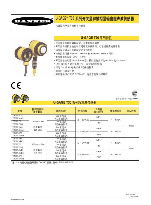
P/N 57438C213001A• 快速简便的按键编程设定,无需电位器调整• 开关量和模拟量输出可以同时或单独使用,可选增量或减量输出• 远程设定输入可保证设定安全和方便• 检测距离可选150mm ~ 1000mm 和300mm ~ 2000mm 两种• 宽范围操作温度-20ºC ~ +70ºC• 开关量输出可选NPN 和PNP 型,模拟量输出可选0 ~ 10V 或4 ~ 20mA • LED 指示灯可显示电源上电,信号强度和输出• 可选2m 或9m 电缆式或5芯接插件式• 紧凑的自含式外型• 防护等级IEC IP67, NEMA 6P ,适应恶劣的外部环境* 注:9m 电缆式需在型号后加“W/30”后缀,例如:T30UUNA W/30U-GAGE T30 系列开关量和模拟量输出超声波传感器U-GAGE T30系统是超声波检测方面一种操作简便、效果理想的超声波传感器。
简单的按键设定方式可满足各种应用场合。
特别是测量方面如液位检测和不同高度物体的分拣等。
每个传感器均有一个模拟量和一个开关量输出端,它们可以设定为具有相同的检测窗口,也可以分别设定为具有不同的检测窗口,每个输出还可设定为以设定点为中心的10mm 宽的检测窗口。
检测窗口检测窗口可以通过多种方法设定,下面介绍按键编程步骤,远程设定端的使用方法见第4页。
注:当传感器处于编程和工作状态之间时,所有指示灯熄灭,然后根据设定状态,相应指示灯亮。
在编程状态时,传感检测窗口为最大范围。
模拟量或开关量窗口设定1. 选择要设定的输出(模拟量或开关量),按住相应按键2 秒以上,直到绿色电源指示灯熄灭,相应的黄色输出指示灯亮,此时传感器进入编程状态。
2. 将检测物放置在第一个位置并按一下按键,使传感器记忆第一个位置,此时,黄色输出指示灯闪,表示第一个位置记忆完毕,准备设定第二个位置。
3. 将被测物放置在第二个位置并按一下按键,使传感器记忆第二个位置,此时,黄色输出指示灯熄灭,绿色电源指示灯亮,此时,传感器进入正常工作状态。
- 1、下载文档前请自行甄别文档内容的完整性,平台不提供额外的编辑、内容补充、找答案等附加服务。
- 2、"仅部分预览"的文档,不可在线预览部分如存在完整性等问题,可反馈申请退款(可完整预览的文档不适用该条件!)。
- 3、如文档侵犯您的权益,请联系客服反馈,我们会尽快为您处理(人工客服工作时间:9:00-18:30)。
P/N 57438
C213001A
• 快速简便的按键编程设定,无需电位器调整
• 开关量和模拟量输出可以同时或单独使用,可选增量或减量输出
• 远程设定输入可保证设定安全和方便
• 检测距离可选150mm ~ 1000mm 和300mm ~ 2000mm 两种
• 宽范围操作温度-20ºC ~ +70ºC
• 开关量输出可选NPN 和PNP 型,模拟量输出可选0 ~ 10V 或4 ~ 20mA
• LED 指示灯可显示电源上电,信号强度和输出
• 可选2m 或9m 电缆式或5芯接插件式
• 紧凑的自含式外型
• 防护等级IEC IP67, NEMA 6P ,适应恶劣的外部环境
* 注:9m 电缆式需在型号后加“W/30”后缀,例如:T30UUNA W/30
U-GAGE T30 系列开关量和模拟量输出超声波传感器
U-GAGE T30系统是超声波检测方面一种操作简便、效果理想的超声波传感器。
简单的按键设定方式可满足各种应用场合。
特别是测量方面如液位检测和不同高度物体的分拣等。
每个传感器均有一个模拟量和一个开关量输出端,它们可以设定为具有相同的检测窗口,也可以分别设定为具有不同的检测窗口,每个输出还可设定为以设定点为中心的10mm 宽的检测窗口。
检测窗口
检测窗口可以通过多种方法设定,下面介绍按键编程步骤,远程设定端的使用方法见第4页。
注:当传感器处于编程和工作状态之间时,所有指示灯熄灭,然后根据设定状态,相应指示灯亮。
在编程状态时,传感检测窗口为最大范围。
模拟量或开关量窗口设定
1. 选择要设定的输出(模拟量或开关量),按住相应按键2 秒以上,直到绿色
电源指示灯熄灭,相应的黄色输出指示灯亮,此时传感器进入编程状态。
2. 将检测物放置在第一个位置并按一下按键,使传感器记忆第一个位置,此时,
黄色输出指示灯闪,表示第一个位置记忆完毕,准备设定第二个位置。
3. 将被测物放置在第二个位置并按一下按键,使传感器记忆第二个位置,此时,
黄色输出指示灯熄灭,绿色电源指示灯亮,此时,传感器进入正常工作状态。
4. 重复以上步骤设定另外一路输出(开关量或模拟量)
注:在设定第二个位置之前,按住相同按键并保持2 秒以上,将退出编程状态,传感器将工作在上次设定的状态下。
使用自动零点特性设定模拟量或开关量输出
在某些应用中,需要以设定点为中心的检测窗口。
设定时只需要对相同位置设定两次,就可以将传感器设定为以该位置为中心,检测窗口宽度为10mm
(±5mm)。
注:设定时允许有一定误差,如果两次位置并不相同(但小于10mm)中心将位于两个位置的中间。
U-GAGE T30 系列开关量和模拟量输出超声波传感器
U-GAGE T30 系列开关量和模拟量输出超声波传感器
使用远程设定端可以对传感器进行远程设定或锁定按键。
锁定按键可以避免现场人员任意更改设定参数。
将灰色线通过开关连接至12 ~ 24V dc。
注:远程设定端输入阻抗为55kΩ。
通过开关产生一系列脉冲进行设定,每个脉冲的脉宽及多个脉冲之间的间隔时间应符合0.04s < T< 0.8s。
* 单脉冲:指示传感器记忆开关量输出的第一编程位置,间隔超过0.8s后,下一个脉冲指示传感器记忆第二个位置
* 双脉冲:指示传感器记忆模拟量输出的第一编程位置,间隔超过0.8s后,下一个脉冲指示传感器记忆第二个位置
* 三脉冲:指示传感器记忆开关量和模拟量双输出的第一编程位置,间隔超过
0.8s后,下一个脉冲指示传感器记忆第二个位置
* 四脉冲:按键锁定或解锁
图2. 远程设定步骤
注:远程设定端保持高电平2 秒以上将退出编程状态,传感器工作在上次设定状态。
U-GAGE T30 系列开关量和模拟量输出超声波传感器
U-GAGE T30 系列开关量和模拟量输出超声波传感器
U-GAGE T30 系列开关量和模拟量输出超声波传感器
U-GAGE T30 系列开关量和模拟量输出超声波传感器
电缆式接插件式
电缆式NPN电缆式PNP
接插件式NPN接插件式PNP
U-GAGE T30 系列开关量和模拟量输出超声波传感器
U-GAGE T30 系列开关量和模拟量输出超声波传感器
Banner Engineering Corp. • Minneapolis, • Tel: 763.544.3164
page 10。