Capless耳机功放SGM4918
瑞信功放产品介绍

PoP-Click 杂音抑制 支持单端和差分输入,可以随心所欲设计 灵活设计,外围简单。 超强抗干扰能力
Page 5
MC4890
1.0W 单声道A/B类 Audio PA
工作电压: 2.5V-5.5V 输出功率: 1.0W@1% THD+N Vdd=5V RL=8Ω THD+N 0.04%@5V 8Ω Po=0.5W Shoutdown 电流0.1uA 热保护功能 封装 :MSOP8/SOP8封装
封装
:TSSOP24
无输出滤波器 调制频率310KHz POP声抑制 高达90%工作效率 短路和热保护自动恢复,带喇叭保护功能 四段增益控制 符合RoHS标准的无铅封装
Page 20
MD4181
4Ω 3.3W低EMI AB/D切换式(F类) Audio PA
工作电压: 2.5V-5.5V 输出功率: 3.4W@10% THD+N Vdd=5.0V RL=4Ω 5.0W@10% THD+N Vdd=5.0V RL=2Ω 1.7W@10% THD+N Vdd=3.7V RL=4Ω 2.4W@10% THD+N Vdd=3.7V RL=2Ω 封装 :ESOP8L
智能切换对FM无干扰,高效率,音质优 输出功率高 ESOP封装时为5W(2Ω负载) 掉电模式漏电流小 外部增益可调,集成反馈 兼容LM4871 符合RoHS标准的无铅封装
Page 21
MD4206
2X3W立体声F 类 Audio PA
工作电压: 2.5V-5.5V 输出功率: 3.1W@10% THD+N Vdd=5.0V RL=4Ω(D类) 2.9W@10% THD+N Vdd=5.0V RL=2Ω(F类) 封装 :SOP16
Sound Blaster Roar Pro MF8171 技术规格说明书

Discover more waysto experience your Sound Blaster Roar Pro!Operating Frequency: 2402 - 2480 MHz: 6000mAhUSB Input: 5V 500 - 1000mADC Output: 5V 1000mA- Standby/Off : 0.2 W- Networked Standby : 1.7 W (Bluetooth)1.9 W (USB)1.9 W (all network ports activated)Power Management- Power consumption < 0.5W after 28 hours inactivity when all network ports are deactivated /disconnected - Networked standby after 20 minutes inactivity (Bluetooth, USB)Activation & deactivation of wireless network port(s)- To activate, perform Bluetooth device pairing- To deactivate, disconnect from external devicePower Adapter InformationModel Number: F J-SW1501600N or GPE024W-150160-ZInput: 100-240VAC 50/60HzOutput: 15VDC 1.6AOperating Temperature range: 0ºC to 45ºCSupported Bluetooth profiles*:A2DP (Wireless Stereo Bluetooth), AVRCP (Bluetooth Remote Control), HFP(Handsfree profile)Supported Codec: SBC, aptX, AACOperating Range: Up to 10 meters, measured in open space.Walls and structures may affect range of device.Supports microSD cards of Class 4 and above, up to 32GB in FAT16/32 formatSupported audio formats: MP3, WMA and WAV (16 bit 48Khz PCM)Support Mp3 and WMA up to 320kbps. Does not support WMA Pro / LosslessRecords audio, voice or mobile calls at 16k, ADPCM WAV format.Note: Compliance markings are located on the bottom of this product.* Refer to your Bluetooth device (notebook¹, PC¹, or mobile device²) manufacturer’s documentation/website for supported profiles.¹ Compatible with PC (Windows XP/Vista/7/8/8.1), Apple Macintoshes equipped withBluetooth wireless stereo.² Compatible with most major brands of Bluetooth A2DP enabled mobile phones.Compatibility DisclaimerWireless performance is dependent on your device’s Bluetooth wireless technology. Refer to your device manufacturer’s manual. Creative will not be liable for any lost of data or leakages resulting from the use of these devices.Product RegistrationRegistering your product ensures you receive the most appropriate service and product support available. You can register your product during installation or at /register. Please note that your warranty rights are not dependent on registration.Safe Removal of Built-in BatteryDetailed instructions on removal of integrated battery can be found at /support/ ROARPRO, these instructions are meant strictly for independently qualified professionals.1. NFC Receptor2. Battery Indicator3. Record Indicator4. Power / Bluetooth® Status Indicator5. Multifunction Button6. Volume Up / Down Button7. Button8. Power ON / Standby Button9. Microphone10. DC Input11. Aux-in / MegaStereo Feature12. DC Out (USB 1.0A)13. Micro USB Connector14. MicroSD Slot15. Mic On / Mute Switch16. Record Button17. (Record) Play / Pause Button18. Random / Repeat All Switch19. Previous Button20. Next Button21. (MP3 Playback) Play / Pause Button22. Energetic, Neutral, Warm Profile23. TeraBass Mode Button24. USB Audio / Mass Storage mode switchTop RearHere’s how you do it!Simply connect a USB cableto the Sound Blaster Roar’sUSB DC Out and the otherend to your smartphone.TIP:Lithium-ion battery life may suffer when it is constantly fully depleted or overexerted at low voltage. It is a good practice to keep the battery well charged.For optimized charging: Creative recommends using the bundled USB cable for optimized charging.PC/MacPower SavingFor better user connectivity experience, the Sound Blaster Roar will now by default automatically enter power saving mode only afterapproximately 28 hours of inactivity when the power adapter is attached via a main outlet to the speaker. However, you have the option to keep the power on permanently if needed.To Disable Power saving mode with power adapter attached (For keeping your speaker ON permanently):1) Ensure that the speaker is powered ON and not connected to any other devices.2) Press the Power and Volume “+“ button together . The LED status indicator will flash once to indicate power saving feature is disabled.To Enable Power saving mode with power adapter attached:1) Ensure that the speaker is powered ON and not connected to any other devices.2) Press the Power and Volume “-“ button together . The LED status indicator will flash once to indicate power saving feature is enabled.Note : The speaker automatically powers down when there is no Bluetooth connection, recording using microSD card, microSD cardplayback or audio input for more than 15 minutes on battery mode. This feature helps to protect the internal battery and cannot be disabled.* Whenever the speaker is ON and connected to a power source, the LED status indicators will continually blink in sequence. To check the battery capacity, power OFF the speaker or disconnect it from the power adapter.Here’s how you do it!1A. One-touch pairing with NFCHere’s how you do it!Simply flick the slider switch Warm – Experience tube like warmth with richness in your vocal, instruments and tones.Neutral – Experience balanced audio from the original Sound Blaster Roar classic that has thousands of reviews all over theWith Creative Bluetooth Multipoint, you can connect up to two Bluetooth devices simultaneously. Toggle easily between your phone and tablet, or share music playback from your phone or a friend’s phone. Here’s how you do it!1Pause playback on theTo toggle between devicesPause playback on the firstconnected device beforestarting playback on thesecond connected device.Note : Creative Muitipoint is not availablewhen the iRoar mic is connected to the SoundBlaster Roar Pro.Like our in-house referencesystems, the Roar is tuned tobe accurate, balanced, and wellPressdefined, while delivering fullspectral output at maximiumlevels with minimal or nocompression. (NOT commonin many battery operatedportables). At low level listeningconditions, some people mayperceive audio differently. Beit being less sensitive to bassreproduction, in less thanideal environments or strictlypersonal preference. TheTeraBass feature intelligentlycompensates the loss ofperceived loudness in bassduring low level playbackwithout artificially overTeraBassPress the TeraBass button while your musicEnhance music playback from your PC/Mac with the powerfulSound Blaster Roar by connecting it with the USB cable supplied.1 Slide the slider switch to USB AudioHere’s how you do it!Enhance your audioTo enhance your digital music further , you can use the Sound Blaster Control Panel software. See next page.Note : If the Sound Blaster Roar is not detected by the computer after your computer recovers from sleep / hibernate / restart, please Power OFF and ON the Sound Blaster Roar to re-establish the USB audio connection. You may also need to restart your computer’s media player .Here’s how you do it!Have complete control over your PC/Mac audio with the Sound Blaster Control Panel software. The SBX Pro Studio technologies – such as SBX Bass and SBX Dialog Plus – intelligently enhance PC/Mac audio in real time. 1 Connect the Sound BlasterHere’s how you do it!1 Insert a microSD card. The Sound Blaster Roar doubles up as a microSD card reader!Here’s how you do it!1 Slide the slider switch to USB Mass Storage toHere’s how you do it!1Insert a microSD card.When your phone isa button!Here’s how you do it!1Connect your smart device.microSD card.Besides playing music at loud volumes, the Sound Blaster Roar can also gently soothe you to sleep. In Bedtime Mode, audio playback from the microSD card will gradually fade out within 15 or 30 minutes, after which the speaker will power off automatically. This is great for parents of young children – you can record yourself reading abedtime story and play it back to your children as they are about to sleep. You can also use it to playmusic before you sleep!Here’s how you do it!1Insert a microSD card.* Patent pendingThe MegaStereo technology is a unique feature built into the Sound Blaster Roar to give you a wider soundstage and double the punch when 2 Sound Blaster Roar are connected together with a MegaStereo cable.Connecting to other audio devices2MASTER (LEFT)SLAVE (RIGHT)May not work with audio devices using the OMTP standard.MASTER (LEFT)SLAVE (RIGHT)*Aux-in for both speakers are disabled when the MegaStereo cable is connected.• For optimum sound performance, it is recommended to connect both speakers to their power adapters.^ MegaStereo feature is only available on the Sound Blaster Roar and Roar Pro. For an updated list of supported speakers please visit. /qr/megastereo ^^Audio may sound unbalanced due to difference in speaker matching.How to use : After establishing connection via the above diagram with the MegaStereo cable, ensure that the slave (Right) unit is set to the maximum volume. Thereafter you may use the Master (Left) speaker to control the volume for both speakers.MegaStereo Cable sold separately.Note : When connected via the MegaStereo Cable, the audio from the two connected Sound Blaster Roars may sound unbalanced after running on battery for an extended period of time. This is due to the difference in the battery levels between the two speakers. For optimum performance, it is recommended to connect both speakers to their power adapters.Transform the Sound Blaster Roar Pro into the next generation portable wireless Public Address (P.A.) System when paired with the Wireless iRoar Mic*. The iRoar Mic delivers clear and loud voice, which is great for power presentations, public speaking, teaching, storytelling or singing!For more information about the iRoar Wireless Mic, please see visit Note : Creative Bluetooth Muitipoint is not available when theiRoar mic is connected to the Sound Blaster Roar Pro.* With optional iRoar Micinformation, please refer to /support.If there is no audio heard after connecting your phone or tablet with the Sound Blaster Roar via Bluetooth........It could be a case of your phone or tablet having a firmware bug that makes it unable to choose the right audio codec. The Sound Blaster Roar can help enhance compatibility by disabling its advanced audio codec and switching only to the basic codec*. However, we advise customers facing this problem to update your phone / tablet with the latest firmware before attempting the following steps below which may just solve this problem.To bypass this bug (by disabling advanced audio codec)1 Ensure that the speaker is Powered on2 Press the Vol “-“and ROAR button together. (A voice prompt is heard indicating Advanced Codec disabled). The speaker will reboot to remember your settings.3 Power OFF and ON your audio device again4 Connect to the Sound Blaster Roar via Bluetooth and play musicTo restore advanced audio codec feature1 Ensure that the speaker is Powered on2 Press the Vol “+“and ROAR button together. (A voice prompt is heard indicating Advanced Codec enabled). The speaker will reboot to remember your settings.3 Power OFF and ON your audio device again4 Connect to the Sound Blaster Roar via Bluetooth and play music* You would only need to do this once and the Sound Blaster Roar will remember your preference. How do I disable Voice Prompt?With the speaker powered ON, press both Volume “–“ and Multifunction Button at the same time.A prompt is heard indicating voice prompt is disabled.How do I enable Voice Prompt?On a speaker with disabled voice prompt, ensure that it is powered ON. Press both Volume “+“ and Multifunction Button at the same time. A prompt is heard indicating voice prompt is enabled. What do I do if I find that the speaker is not behaving the way it should?Should any of the above happens, we would recommend that you master reset the speaker.In any state, press and hold the Power button for more than 10 seconds then press the Power button again to turn on the speaker.AlternativelyYou can perform a factory master reset to clear paired device list.1 Ensure your speaker is not connected to any Bluetooth device.2 With your speaker powered on, Press and hold the Multifunction button until the white LED blinks rapidly. Press and hold the Multifunction button and Volume “-“ button until a voice prompt is heard indicating the speaker has been master reset and returned to pairing mode. Why do I hear beep tones when I disable voice prompts?The beep tones are meant to be indicators for the following items:1 Beep tone2 Beep tone3 Beep tone Feature activated indicator Feature confirmation indicator Error indicator For the latest, online version of this guide,visit /support/ROARPROSupplementary documentation for this product includes:DoC, safety and regulatory information, ErP Regulatory information, and other related regulatory notices. For more details please visit /support/ROARPRO Creative warrants that the accompanying product is free from material or workmanship defects for a period of 12 months (non-transferable Creative Warranty period) from your purchase date. In the event of a genuine product failure, Creative will assume repair or part replacement (new or refurbished) within the Creative Warranty period. However, this Creative Warranty does not cover (but not limited to) normal wear and tear, abnormal usage, improper storage and handling, unauthorised modifications or repair, damages arising from an Act of God and theft. In the event of a genuine product failure you must provide Creative with the product and proof of purchase of the product by a dated itemised receipt. For the entire details on the Creative Warranty period of your product, Creative Warranty terms, product returns and repair procedure, and Creative Customer Support services and contact information, you are advised to refer to our website at . From here, select your country of residence and proceed to the Support section. We also recommend you to register your product with us at /register to enjoy a host of additional product benefits that includes latest news and promotions. Note that your entitlement to the Creative Warranty is not dependent on product registration. Please note the Creative Warranty does not affect your statutory rights. Thank you.The limited warranty for the Product is for twelve (12) months (for the European Union, twenty-four (24) months (excluding all wear and tear), subject to certain exceptions as stated in the EU Directive 1999/44/EC**) from the date of Your purchase (“Warranty Period”). The Warranty Period will be extended by each whole day that the Product is out of Your possession for repair under this warranty.**Only Applicable for European (EU) countries A seller in the European Union (EU) may be entitled to refuse to repair or replace the goods if it is (i) impossible or (ii) disproportionate (eg. where the costs are unreasonably high for the seller) to do so, taking into account the value the goods would have had (if there were no lack of conformity), the significance of the lack of conformity and where an alternative remedy would be completed without significant inconvenience to the consumer. In such cases, the consumer may ask for an appropriate reduction of the price or have the contract rescinded. The consumer is not entitled to have the contract rescinded if the lack of conformity (or defect or fault) is minor. In which case, the seller is entitled to turn down a request for rescission of the contract in such a situation. For further details, please refer to Articles 3(3), 3(5) and 3(6) of the EU Directive 1999/44/EC.For Australia only: Our goods come with guarantees that cannot be excluded under the Australian Consumer Law. You are entitled to a replacement or refund for a major failure and for compensation for any other reasonably foreseeable loss or damage. You are also entitled to have the goods repaired or replaced if the goods fail to be of acceptable quality and the failure does not amount to a major failure. (Creative T echnology Ltd, 31 International Business Park, #03-96, Creative Resource, Singapore 609921. T elephone: +65 6895 4433 (standard international call charges apply.)Creative Limited Hardware Warranty (“Creative Warranty”)© 2016 Creative T echnology Ltd. All rights reserved. Creative, the Creative Logo, Sound Blaster, Sound Blaster Roar and SBX Pro Studio are trademarks or registered trademarks of Creative T echnology Ltd. in the United States and/or other countries. T he Bluetooth word mark and logo are owned by the Bluetooth SIG, Inc. and any use of such marks by Creative T echnology Ltd is under license. aptX is a trademark of CSR plc. microSDHC Logo is a trademark of SD-3C, LLC. All other trademarks are the property of their respective owners and are hereby recognized as such. All specifications are subject to change without notice. Actual product may differ slightly from images shown. Use of the product is subject to a limited warranty.。
艾为电子技术 AW8731 超大音量、防破音、超低 EMI、K 类音响功率放大器 产品手册
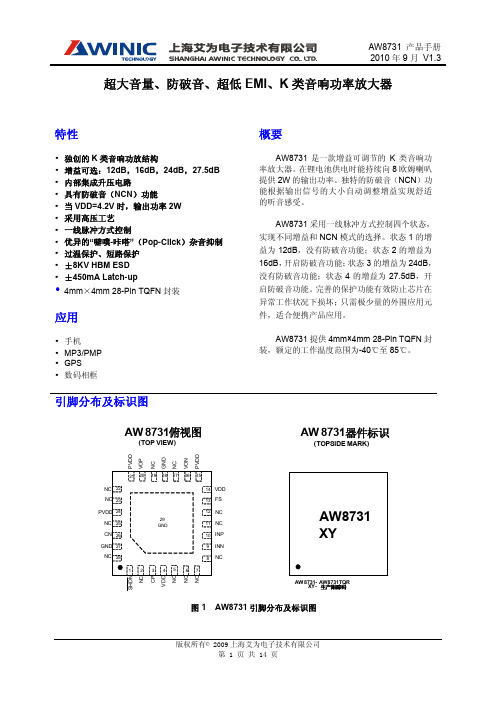
超大音量、防破音、超低EMI 、K 类音响功率放大器引脚分布及标识图S H D NN C V D N N N NCINN INP NC NC FS VDD P V D DV O PN CG N DN CV O NP V D DAW 8731 (TOP VIEW)AW 8731 (TOPSIDE MARK)AW 8731 - AW8731TQRXY -生产跟踪码器件标识俯视图图 1 AW8731引脚分布及标识图特性y 独创的K 类音响功放结构y 增益可选:12dB ,16dB ,24dB ,27.5dB y 内部集成升压电路y 具有防破音(NCN )功能y 当VDD=4.2V 时,输出功率2W y 采用高压工艺y 一线脉冲方式控制y 优异的“噼噗-咔嗒”(Pop-Click )杂音抑制 y 过温保护、短路保护 y ±8KV HBM ESD y±450mA Latch-upy 4mm ×4mm 28-Pin TQFN 封装 应用y 手机y MP3/PMP y GPS y 数码相框概要AW8731是一款增益可调节的K 类音响功率放大器。
在锂电池供电时能持续向8欧姆喇叭提供2W 的输出功率。
独特的防破音(NCN )功能根据输出信号的大小自动调整增益实现舒适的听音感受。
AW8731采用一线脉冲方式控制四个状态,实现不同增益和NCN 模式的选择。
状态1的增益为12dB ,没有防破音功能;状态2的增益为16dB ,开启防破音功能;状态3的增益为24dB ,没有防破音功能;状态4的增益为27.5dB ,开启防破音功能。
完善的保护功能有效防止芯片在异常工作状况下损坏;只需极少量的外围应用元件,适合便携产品应用。
AW8731提供4mm×4mm 28-Pin TQFN 封装,额定的工作温度范围为-40℃至85℃。
典型应用图图 2AW8731差分输入方式应用图订购信息产品型号工作温度范围封装形式器件标识发货形式AW8731TQR -40℃~85℃4mmX4mm28-Pin TQFNAW8731卷带包装3000 片/盘引脚定义及功能序号符号描述——————关断引脚,低有效;支持一线脉冲方式控制。
Audioengine 产品3年有限保修说明书

How to obtain Audioengine Warranty service If you have any questions about your warranty coverage or you feel you may need service, email the Audioengine US Service Center: support@ or call toll-free in the US: (877) 853-4447
Bluetooth RCA stereo, optical (SPDIF) 2.0V RMS 57 ohms 10Hz - 20kHz (+/-0.5dB) >100dB (1 kHz FS 96 kS/s) <0.02% >-86dB aptX, A2DP and AVRCP 5V, 200mA AKM AK4396 up to 100ft (30m) typical 3.5 x4.0 x1" 1.0lbs (0.5kg)
FCC Part 15 Notice
This device complies with Part 15 of the FCC Rules. Operation is subject to the following two conditions:
1) This device may not cause harmful interference. 2) This device must accept any interference received, including interference that may cause undesired operation.
Information for Users on Disposal of Old Equipment
NY9A008A_v1.0(PWM音频功放IC)

NY9A008APower PWM Audio AmplifierVersion 1.0Aug. 5, 2014NYQUEST TECHNOLOGY CO. reserves the right to change this document without prior notice. Information provided by NYQUEST is believed to be accurate and reliable. However, NYQUEST makes no warranty for any errors which may appear in this document. Contact NYQUEST to obtain the latest version of device specifications beforeRevision History1. 概述NY9A008A 為單晶片CMOS的PWM 音頻功率放大器IC,利用大型積體電路(LSI)製造技術,具有低電源及低成本的特性,在使用時只需要很少的週邊元件,並可應用於高電壓工作模式。
電路內置大功率MOSFET 的Power PW M 驅動線路,可用來實現對 PWM 音頻的放大。
2. 功能(1). 寬廣的工作電壓: 1.8V ~ 9.0V。
(2). 內置大功率 PMOS/NMOS 的 Power PWM 驅動器。
※注意: 由於Power PWM 的輸出功率很大,0.25W喇叭會被燒毀,請搭配0.5W以上的喇叭。
(3). 低待機電流(Typ.=0.1uA)。
(4). 800mA 以上電流輸出能力。
(5). CMOS 輸入,輸入腳內建下拉電阻,無需外加限流電阻。
(6). 高達 5KV 的人體靜電模式 (HBM) 的 ESD 保護。
(7). 僅提供SOP-8 封裝出貨。
1. GENERAL DESCRIPTIONNY9A008A is a single-chip Audio Amplifier PWM driver CMOS IC. It is designed by LSI high technology with a low-power and low-cost process, and can be applied at high voltage application. It has built-in Power PWM driver with large power MOSFET circuit to amplify PWM audio signal.2. FEATURES(1). Wide operating voltage: 1.8V ~ 9.0V.(2). Built-in Power PWM driver of large power PMOS/NMOS circuit.※ Note: Due to large power of Power PWM output, 0.25W speaker will be damaged and 0.5W or above speaker is suggested.(3). Low standby current. (Typ.=0.1uA)(4). Over 800mA output current capability.(5). CMOS input. Built-in input pull-low resistance and no current-limit resistance required.(6). High 5KV Human Body Mode (HBM) ESD protection.(7). Only SOP-8 package type is available.3. BLOCK DIAGRAMIN1IN2VCC GND OUT1OUT2VDD4. PIN DESCRIPTIONPin NamePin No. ATTR. DescriptionIN1 2 I PWM signal input 1. IN2 3 I PWM signal input 2. PWM1 7 O Power PWM output 1. PWM2 6 O Power PWM output 2.VDD 1 Power Positive power of logic control circuit. VCC 4 Power Positive power of Power PWM. GND 5 Power Negative power. NC 8NCNo connect.PWM1 PWM2GNDVCCVDD IN1 IN25. ELECTRICAL CHARACTERISTICS5.1 Absolute Maximum RatingSymbol Parameter Rating Unit V DD - V SS Supply voltage of logic control circuit -0.5 ~ +7.5 V V CC Supply voltage of Power PWM 9.6 VI OUT-PEAK Output peak current 1.0 AθJAThermal resistance(Junction to Ambient)SOP-8 150 °C/WP D Power dissipation SOP-8 0.9 W T A Operating ambient temperature -40 ~ +85 °C T J Operating junction temperature +160 °C T ST Storage temperature -55 ~ +160 °C5.2 DC CharacteristicsSymbol Parameter Min. Typ. Max. Unit Condition V DD Operating voltage (Logic) 1.8 6.8 VV CC Operating voltage (PWM) 1.8 9.0 VI SB Standby current 0.1 1 uA IN1=IN2=0I OP OperatingcurrentV DD =V CC =3.0V 25 uAPWM=20kHz, Duty=50% V DD =V CC =6.0V 35 uAI IHInput high current(12kΩ pull-low resistance)260 uA V IH =3.0V510 uA V IH =6.0VV IH Input high voltage 0.7V DD VV IL Input low voltage 0.3V DD VI OUT Output continuous current 800 850mA SOP-8T RISE Output rise time 46 nsPWM=20kHz, Duty=50% T FALL Output fall time 35 nsT RP Input-to-Output response time 65 ns(V DD=3.0V, V CC=6.0V, T A=25ºC, unless otherwise specified)6. APPLICATION CIRCUIT(1) Single Power(2) Dual Power* If voltage is higher than 6.0V, C1 (0.1uF) is necessary for endure high voltage.7. PACKAGE DIMENSION8. ORDERING INFORMATIONNote: For 8-pin SOP IC, 100 units per tube.。
BOSS GT-6效果处理器中文说明书

z 在国外使用本机时,请洽询最近的 Roland 服务中心,或 Roland 授权代理 商(详列于”Information”)。
z 请将本机与 AC 电源变压器置于通风良好 的地方。
z 将插头插入或拔离插座时,一定要捉住 AC 电源变压器的插头部分。
z 不论该器材是否将长时间闲置,请移除与 AC 电源变压器的连接。
64midi功能设定65第六章使用自定功能53传送与接收midi数据67进行自定前级放大器设定53传送数据到外接midi设备bulkdump67进行自定过载失真失真设定54从外接midi设备接收数据bulkload68进行自定踏板哇设定55设定音色改变对应69开启关闭音色改变对应的设定midimapselect69第七章gt6的便捷功能56快速音色音量调整patchlevel旋钮56附录70使用踏板来开启与关闭效果器manualmode56关于midi70切换到手动模式56midi讯息传送与接收的方式70选择要用踏板来切换开启与关闭的效果器56gt6使用的midi讯息主要类型70手动模式下比较前级放大音色57关于midiimplementation71吉他调音57开启调音器功能57使用音色库选择讯息来改变音色72调音时的屏幕显示57从gt6改变外接midi设备上的音色号码72调音方法58改变调音器设定58使用外接midi设备传送过来的音色库选择讯息改变gt6上的音色号码73使用号码踏板来切换调音器的开启与关闭59调整整体音量以配合使用环境global59原厂设定74使用外接效果器60回复原厂设定值factoryreset74使用数字输出60使用级数测量来检查效果器输出强度60故障排除75错误讯息76第八章其它功能61调整屏幕对比lcdcontrast61midiimplementationchart77选择patchvalue转盘功能dialfunction61规格78wwwrolandcomcn主要特色可制造最大失真效果的内建cosm前级仿真与cosm负载失真失真表情踏板表情踏板开关与控制踏板由cosm前级仿真与cosm负载失真失真高度进化的组合将为您的表演提供最强而有力的失真效果
唯创知音电子 WT85711功放芯片说明书

WT85711功放芯片说明书V1.02 Note:WAYTRONIC ELECTRONIC CO.,LTD.reserves the right to change this document without prior notice. Information provided by WAYTRONIC is believed to be accurate and reliable.However,WAYTRONIC makes no warranty for any errors which may appear in this document.Contact WAYTRONIC to obtain the latest version ofdevice specifications before placing your orders.No responsibility is assumed by WAYTRONIC for any infringement of patent or other rights of third parties which may result from its use.In addition,WAYTRONIC products are not authorized for use as critical components in life support devices/systems or aviation devices/systems,where a malfunction or failure of the product may reasonably be expected to result in significant injury to the user,without theWT85711输出功率Po at 10%THD+N,VDD=5V RL=4Ω3.12W(典型值)RL=2Ω5.00W(典型值)Po at 10%THD+N,VDD=3.7V RL=4Ω1.77W(典型值)RL=2Ω2.63W(典型值)・AB 类/D 类工作模式切换功能独创的AERC 技术提供优异的全带宽EMI 抑制能力优异的”噼噗-咔嗒"(pop-noise)杂音抑制能力优异的低噪扣制功能・反馈电阻300K・工作电压范围:2.5V 到5.5V 无需滤波的Class-D 结构・高达90%的效率高电源抑制比(PSRR):在217Hz 下为72dB ・快速的启动时间(150ms)低静态电流(5mA)低关断电流(<0.1pA)过流保护,短路保护和过热保护符合Rohs 标准的无铅封装应用・USB 音箱/篮牙音箱・扩音器典型应用图AB/D 切换,5.0W 单声道音频功率放大器WT85711是一款FM无干扰、AB类功放D类功放两种模式可切换的5.0W单声道音频放大器WT85711采用独创的AERC(Adaptive Edge Rate Contro1)技术,能提供优异的全带宽EMI抑制能力,在不加任何辅助设计时,在FCC Part15Class B标准下仍然具有超过20dB的裕量WT85711无需滤波器的PWM调制结构及增益内置方式减少了外部元件、PCB 面积和系统成本,并简化了设计。
Whirlwind Qbox-aes 数字和模拟音频信号故障诊断设备说明书

The Whirlwind Qbox-aes is a multipurpose testing device for troubleshooting digital AES-3, S/PDIF and analog audio signals. It is composed of two sections; a Send section and a Receive/Monitor section. A Test Mode switch selects Analog or AES testing operation. Audio is decoded and output through the built-in speaker or the 3.5mm jack. Test signals can be generated from multiple sources. In Line monitoring of an AES data stream is also possible with no alteration of the signal passing through.Theory of OperationAES/EBU TEST MODEThe Qbox-aes is designed to provide a portable means of testing various aspects of AES-3 and S/PDIF digital audio systems. With the Test Mode switch in the AES/EBU (IN) position, it is able to generate AES-3 or S/PDIF output signals at sample frequencies of 48 kHz, 96 kHz and 192 kHz. Audio sources for the Send function include a built-in microphone, a pair of tone generators (440 Hz for the left channel, 660 Hz for the right), and a 3.5mm, unbalanced stereo input, for an MP3 or CD player, computer sound card, etc. A Send Level control adjusts the selected source level into the digital encoder for output through the Send jacks.The Qbox-aes is capable of decoding professional and consumer AES-3 or S/PDIF signals, displaying sample frequencies from 44.1 kHz to 192 kHz and monitoring the audio content via the built-in speaker or Line/Phones Monitor jack. There are two digital operating modes available: Send/Receive Test and In Line Monitor as selected by the AES Function switch. Each of these modes is described in detail in the following paragraphs.Send/Receive Test functionWhen using Send/Receive Test mode, the internal digital receiver will lock to useable AES-3 or S/PDIF signals applied to the input connectors. When locked, the appropriate Receive Sample Rate LED will indicate the detected sample rate. The Non AES Input LED illuminates anytime that the digital input signal is a non-PCM format, and cannot be decoded as audio or when the input is analog. The digital audio is decoded and presented to both the speaker and the Line/Phones Monitor jack. The digital Send section will convert the selected test signal (mic, aux or tone) to digital format and output it from the digital Send jacks at the sample rate set by the S/R Test Sample Rate switch (48, 96 or 192 kHz). The Send Level control adjusts the amount of output signal delivered to the Send jacks. There are two green LEDS that illuminate when the analog input to the A/D converter reaches +4 dB. This results in a digital output of approximately -12 dBfs. With the level control at full clockwise the digital output is equal to 0.6 dBfs when using the internal oscillators as a signal source.Send/Receive Test mode can be used for cable testing. The selected test signal is driven out of the digital Send at the sample rate selected by the sample rate switch. If a good cable is connected between the Send and Receive, the Sample Rate indicators will display the detected sample rate and the selected test signal will be heard over the speaker and the line output. When testing a cable to determine if it has high-frequency problems, select the highest sample rate. If the digital receiver is able to lock to the signal, chances are that the cable is good. If the cable has integrity problems, it may not lock at a rate of 192kHz, but may lock at a lower sample rate. Connecting a short cable between Send and Receive also provides an excellent means of performing an end-to-end test of the Qbox-aes itself, allowing the operator to test the functionality of all the internal components.In line Monitor Only functionIn Line Monitor mode is used to monitor a digital audio signal without interrupting its destination, essentially acting as a wiretap. The digital audio input signal is decoded and the serial data stream is fed to the digital-to-analog converter for analog monitoring and to the digital output encoder for re-transmission without passing through the analog domain. To use this mode, the signal source cable is connected to one of the digital Receive connectors, and the signal destination cable is connected to one of the digital Send connectors. When the input signal is present, the appropriate Sample Rate indicator will illuminate and the input signal will be present on the digital output connector. The input signal, in analog format, is available at the speaker and the Line/Phones Monitor jack. Any analog input sources are ignored, as well as the S/R Test Sample Rate switch.Receive/Monitor SectionThe Receive Sample Rate LEDs indicate the detected sample rate when they are locked to the digital input. Only one LED will be illuminated at a time, except during the Power-On Self-Test. Displayed sample rates are 44.1kHz, 48kHz, 88.2kHz, 96kHz, 176.4kHz, and 192kHz. The Qbox-aes can detect both versions of the AES-3 bitstream; professional and consumer.Analog monitoring of the digital input signal is done through the internal speaker or externally by connecting an amplifier or headphones to the Line/Phones Monitor jack. Peak output level is +5 dBv, and the output is capable of driving headphones from 32 to 100 Ohms impedance. This output and the speaker are controlled by the Monitor Volume level control. A three position Speaker switch allows individual monitoring of Channel A (left) or the Channel B (right) signal from the digital stream. In the center position, the A and B signals are both fed to the speaker simultaneously. Using the Line/Phones Monitor jack mutes the speaker and is always in stereo.ANALOG TEST MODEThe Qbox-aes provides testing of balanced and unbalanced analog audio signals. With the Test Mode switch in the Analog (OUT) position, the Send and Receive XLR connectors bypass the digital circuitry. The Mic, Oscillator and Aux signals are controlled by the Send level control and output through the male Send XLR. The female Receive XLR accepts analog input and delivers it to the Speaker and Line/Phones Monitor jack through the Volume control. A three position switch allows the selection of a balanced input or unbalanced pin 2 or pin 3 to be monitored separately and Phantom LEDS indicate the presence of phantom power at the male XLR. The Non AES Input LED will be lit continuously.The Qbox-aes is powered by a 6 volt DC wall power supply (model # PS6) or four “AA” cells. Peak power requirement is 6 Watts. Average power requirement is 2.2 Watts. The largest factor in power draw is the setting of the speaker volume.WarrantyThis product is guaranteed for 5 years from the date of purchase against manufacturing defects. For warranty service, return the unit, along with the original sales receipt, to: whirlwind, 99 Ling Road, Rochester, NY 14612, postage prepaid. We will repair or replace the unit at our option and pay the return postage.Q box-aesAES/Analog Signal Tester99 Ling Road . Rochester, NY 14612 Phone 585 663-8820 . Fax 585 865-8930Email:**********************05/201712. Monitor Volume adjusts the volume of the built-in speaker and the level of the signal at the Line/Phones Monitor jack.13. Green A and B Send LEDS display the amount of analog signal sent to the A/D converter in AES Test mode and at the Send Xlr in Analog Test mode. They illuminate when the when the analog input to the A/D converter reaches +4 dBv. This results in a digital output of approximately -12 dBfs. The send level in Analog mode is -10.4 dBv.14. Send Level controls the analog level presented to the A/D Converter input. The mic, tone oscillators, and aux input are affected by this control, typically adjusted to a level where the +4 green LEDs begin to turn on. With the level control at full clockwise the digital output is equal to 0.6 dBfs when using the internal oscillators as a signal source. Maximum analog signal Send output level is 4.7 dBv.15. S/R Test Sample Rate switch sets the sample rate of the digital AES stream output from the Send jacks in Send/Receive Test mode.. It is able to generate AES-3 or S/PDIF output signals at sample frequencies of 48 kHz, 96 kHz and 192 kHz. In line Monitor mode bypasses any setting of this switch and the Send sample rate matches that of the input at the Receive jacks.16. Send Source switch selects the audio source for the Send function. The Mic position selects the built-in microphone, the Tone/Aux position connects a pair of tone generators (440 Hz for the left channel, 660 Hz for the right). Plugging into the Aux TRS Input disconnects the dual oscillators and accepts an external unbalanced stereo source. In Analog Test mode both oscillator frequencies are summed together and sent out the balanced Send XLR.17. Line/Phones Stereo Monitor Jack provides a high-quality output of any audio source received. Peak output level is +4dB, and the output is capable of driving headphones from 32 to 100 Ohms impedance. The left channel is connected to the tip, the right to the ring, and the sleeve to common of the unbalanced 3.5mm TRS jack. Volume is controlled by the Monitor Volume control. Connecting to this jack mutes the speaker and is always stereo in AES Test mode.18. Aux TRS Input jack allows the operator to connect any analog source to the unit. The maximum input level is +5 dBv. This is an unbalanced 3.5mm TRS jack with the left channel connected to the tip, the right to the ring, and the sleeve to common.19. Send BNC outputs standard S/PDIF digital audio signals over 75 Ohm coaxial cable at 5V p-p. In AES Test mode with the unit off, the XLR and BNC can also be used as a loop thru balun. This jack is not used for Analog Test mode.20. Send XLR outputs standard AES-3 digital audio signals over 110 Ohm balanced shielded cable at 5V p-p in AES Test mode, and with the unit off the XLR and BNC can be used as a loop thru balun. In Analog Test mode the output is balanced and the max level is 4.7 dBv with the Send Volume control turned fully clockwise.Controls and Functions1. Test Mode switch selects the type of signal that the Qbox-aes will analyze. The Out position is for testing analog signals and the In position is for AES digital types. It is recommended that the operator turn the unit on and set the proper mode before connecting to the device being tested.2. Receive female XLR connector is used as an input for standard AES-3 digital audio signals over 110 Ohm balanced shielded cable and balanced or unbalanced analog signals, corresponding to the position of the Test Mode switch.3. Receive BNC jack accepts standard unbalanced AES or S/PDIF digital inputs only over 75 Ohm coaxial cable. This jack is disconnected in the analog Test Mode. Input levels for both jacks may be as high as 5 V p-p and as low as 360 mV p-p. Input sample rates may range from 44.1 kHz to 192 kHz. The two jacks are transformer isolated and may be used as a loop thru balun for converting from 110 Ohm to 75 Ohm transmission lines in AES test mode.6. Input Sample Rate LEDs indicate the detected sample rate when locked to a digital audio input. Only one will be illuminated at a time, except during the Power-On Self-Test. The Non-AES Input LED illuminates anytime a valid AES signal is not present.7. 6VDC external power jack is a 5.5mm x 2.1mm size with the center contact wired positive and the barrel contact negative. A 6VDC 1000mA plug-in power supply (model # PS6) with the correct mating connector is supplied with the unit.8. Battery Compartment is a slide out drawer that accepts four “AA” cells. New alkaline batteries will last approx. 6 hours, but battery life reduces to about 1 hour with the speaker at full volume.9. Analog Pin 2 and Pin 3 green LEDs sense the presence of phantom or intercom power at the male Send XLR when the unit is in Analog test mode. Connect to the female XLR to monitor intercom audio.10. Analog Pin 2 and Pin 3 switch has three positions for listening to balanced or unbalanced analog signals connected to the Receive XLR. The center position is for balanced inputs and the Pin 2 and Pin 3 positions provide individual monitoring of each pin separately.11. Speaker Monitor A/B switch controls which of the two available digital audio channels is presented to the speaker for monitoring. In the center position, the A and B signals are both on and is the proper position when using Analog Test mode. Changing the switch position in Analog mode will vary the volume but not the source signal.1231117181920 4. AES Function switch chooses the manner of digital testing to be performed by the Qbox-aes. In Line Monitor Only mode is used to listen to a digital audio signal without interrupting its destination. The unit bridges the data stream for monitoring and passes it through without alteration. With a digital input signal present and locked, the digital output sample rate will mimic the sample rate of the digital input and the Sample Rate switch has no effect. Send/Receive Test mode configures the Send and Receive sections to work independently. The selected test signal is driven out of the digital Send at the sample rate selected by the sample rate switch. When an AES input is received and locked the appropriate Receive Sample Rate LED will indicate the detected sample rate. The digital audio is decoded and presented to both the speaker and the Line/Phones Monitor jack.5. Power Switch applies power from the external supply or the batteries and the blue LED illuminates when the Power switch is ON. The Qbox-aes performs a self test when first turned on, indicated by the sample rate LEDs. It is recommended that the unit complete it's self test before connecting to the device to be tested. All connections should be removed before turning the unit off.。
- 1、下载文档前请自行甄别文档内容的完整性,平台不提供额外的编辑、内容补充、找答案等附加服务。
- 2、"仅部分预览"的文档,不可在线预览部分如存在完整性等问题,可反馈申请退款(可完整预览的文档不适用该条件!)。
- 3、如文档侵犯您的权益,请联系客服反馈,我们会尽快为您处理(人工客服工作时间:9:00-18:30)。
SGM491880mW, Capless, Stereo Headphone Amplifier with ShutdownGENERAL DESCRIPTIONThe SGM4918 stereo headphone amplifier is designed for portable equipment where board space is at a premium. The SGM4918 uses capless architecture to produce a ground-referenced output from a single power supply, eliminating the need for large DC-blockingcapacitors for output, saving cost, board space, and component height. Additionally, for SGM4918B, the gain is set internally (-2V/V), further reducing component count. For SGM4918A, the gain can be adjusted by external feedback resistors.The SGM4918 delivers up to 80mW per channel into a 32Ω load and has low 0.03% THD+N. A -78dB power supply rejection ratio (PSRR) at 217Hz allows this device to operate from noisy digital supplies without an additional linear regulator. Comprehensive click-and-pop circuitry suppresses audible clicks and pops on startup and shutdown.The SGM4918 operates from a single 2.7V to 5.2V supply, consumes only 5.8mA supply current, has short-circuit and thermal-overload protections, and is specified over the extended -40°C to +85°C temperature range. The SGM4918 is available in a Green TDFN-3×3-10L package.FEATURES∙ SGM4918A: External Feedback Gain Network SGM4918B: Fixed -2V/V Gain∙ No Bulky DC-Blocking Capacitors Required ∙ Ground-Referenced Outputs Eliminate DC-Bias Voltage on Headphone Ground Pin∙ No Degradation of Low-Frequency Response Due to Output Capacitors∙ 80mW into 32Ω Load from 5V Power Supply at THD+N = 0.1% (TYP, per Channel) ∙ Low 0.03% THD+N∙ High PSRR (-78dB at 217Hz)∙ Integrated Click-and-Pop Suppression ∙ 2.7V to 5.2V Single Supply Operation ∙ Low Quiescent Current (5.8mA at V DD = 5V) ∙ Shutdown Control∙ Short-Circuit and Thermal-Overload Protections ∙ Undervoltage Lockout Function∙ -40℃ to +85℃ Operating Temperature Range ∙ Available in Green TDFN-3×3-10L PackageAPPLICATIONSNotebook PCs Cellular Phones PDAs MP3 Players Smart PhonesPortable Audio EquipmentREV. A. 1SG Micro Corp.Amplifier with Shutdown2SGM4918SG Micro Corp.PACKAGE/ORDERING INFORMATIONMODEL ORDER NUMBERPACKAGEDESCRIPTIONGAIN (V/V)MARKING INFORMATIONPACKAGE OPTION SGM4918A SGM4918AYD10G/TR TDFN-3×3-10L ADJSGM 4918AD XXXXX Tape and Reel, 3000SGM4918B SGM4918BYD10G/TR TDFN-3×3-10L -2 SGM 4918BD XXXXXTape and Reel, 3000NOTE: XXXXX = Date Code and Vendor Code.ABSOLUTE MAXIMUM RATINGSV DD to GND…………………………..........................-0.3V to +6V C1P to GND............................................... -0.3V to (V DD + 0.3V) C1N to GND.............................................. (V SS - 0.3V) to + 0.3V V SS to GND .............................................................-6V to +0.3V OUTR, OUTL to GND...................... (V SS - 0.3V) to (V DD + 0.3V)SHDN toGND....................................................... -0.3V to +6V INR, INL to GND.............................. (V SS - 0.3V) to (V DD + 0.3V) Output Short Circuit to GND or V DD ...........................Continuous Junction Temperature........................................................150℃ Operating Temperature Range ...........................-40℃ to +85℃ Storage Temperature Range .............................-65℃ to +150℃ Lead Temperature (Soldering, 10s) ..................................260℃ESD SusceptibilityHBM ..................................................................................3000V HBM (Output pins to Supply and Ground pins)..................4000V MM (200V)NOTE:Stresses beyond those listed under “Absolute Maximum Ratings” may cause permanent damage to the device. These are stress ratings only, and functional operation of the device at these or any other conditions beyond those indicated in the operational sections of the specifications is not implied. Exposure to absolute maximum rating conditions for extended periods may affect device reliability. CAUTIONThis integrated circuit can be damaged by ESD if you don’t pay attention to ESD protection. SGMICRO recommends that all integrated circuits be handled with appropriate precautions. Failure to observe proper handling and installation procedures can cause damage. ESD damage can range from subtle performance degradation to complete device failure. Precision integrated circuits may be more susceptible to damage because very small parametric changes could cause the device not to meet its published specifications.SGMICRO reserves the right to make any change in circuit design, specification or other related things if necessary without notice at any time. Please contact SGMICRO sales office to get the latest datasheet.Amplifier with Shutdown3SGM4918SG Micro Corp.PIN CONFIGURATION (TOP VIEW)C1N V SS C1P OUTL INL GND V DD TDFN-3×3-10LOUTRINRSHDNPIN DESCRIPTIONSAmplifier with Shutdown4SGM4918SG Micro Corp.ELECTRICAL CHARACTERISTICS(T A = +25°C, V DD = SHDN = 5V, V GND = 0V, R IN = R F = 40k Ω (gain = -1V/V), C1 = C2 = 1µF, C3 = 4.7µF, C4 = 0.1µF, R L = ∞, unlessotherwise noted.) (1)NOTE:1. For R IN , R F , C1 and etc, please refer to the FUNCTIONAL DIAGRAM/TYPICAL APPLICATION CIRCUIT on page 8.Amplifier with Shutdown5SGM4918SG Micro Corp.TYPICAL PERFORMANCE CHARACTERISTICSOutput Power (mW)Output Power (mW)Output Power (mW)Amplifier with Shutdown6SGM4918SG Micro Corp.TYPICAL PERFORMANCE CHARACTERISTICSAmplifier with Shutdown7SGM4918SG Micro Corp.TYPICAL PERFORMANCE CHARACTERISTICSAmplifier with Shutdown8SGM4918SG Micro Corp.FUNCTIONAL DIAGRAM/TYPICAL APPLICATION CIRCUITNOTE:1. In order to get good performance, it’s important to select the right C1, C2 and C3 in application. All tests are performed with circuit set up with X5R and X7R capacitors. Capacitors having high dissipative loss, such as Y5V capacitor, may cause performance degradation and unexpected system behavior.Amplifier with Shutdown9SGM4918SG Micro Corp.PCB LAYOUT GUIDE31245TDFN-3×3-10LC40.1μFThe reference PCB layout is shown below:NOTES:1. To ensure the normal operation of the device, decoupling capacitors (C3 and C4) must be placed as close to SGM4918 as possible. The loop length formed by C3/C4, V DD and GND should be no longer than 5mm; otherwise the device will not start up at high supply voltage.2. Proper layout and ground connection are essential for optimum performance. Connect Exposed Paddle and GND together at a single point on the PCB. Ensure ground return resistance is minimized for optimum THD and crosstalk performance. Place the power-supply bypass capacitor, the charge-pump hold capacitor, and the charge-pump flying capacitor as close as possible to the SGM4918. Route all traces that carry switching transients away from the audio signal path.Amplifier with Shutdown10SGM4918SG Micro Corp.PACKAGE OUTLINE DIMENSIONSTDFN-3×3-10LRECOMMENDED LAND PATTERN (Unit: mm)ASIDE VIEWBOTTOM VIEWTOP VIEWDimensions In Millimeters Dimensions In InchesSymbolMIN MAX MIN MAXA 0.700 0.800 0.028 0.031 A1 0.000 0.050 0.000 0.002 A20.203 REF0.008 REFD 2.900 3.100 0.114 0.122 D1 2.300 2.500 0.091 0.098E 2.900 3.100 0.114 0.122 E1 1.600 1.800 0.063 0.071 k 0.200 MIN 0.008 MIN b 0.180 0.300 0.007 0.012 e0.500 TYP0.020 TYPL 0.300 0.500 0.012 0.020Amplifier with Shutdown11SGM4918SG Micro Corp.TAPE AND REEL INFORMATIONNOTE: The picture is only for reference. Please make the object as the standard.KEY PARAMETER LIST OF TAPE AND REELPackage TypeReel Diameter Reel WidthW1(mm)A0 (mm)B0 (mm)K0 (mm)P0 (mm)P1 (mm)P2 (mm)W (mm)Pin1 QuadrantTDFN-3×3-10L 13’’ 12.4 3.35 3.351.134.008.00 2.00 12.00Q1REEL DIMENSIONSAmplifier with Shutdown12SGM4918SG Micro Corp.CARTON BOX DIMENSIONSNOTE: The picture is only for reference. Please make the object as the standard.KEY PARAMETER LIST OF CARTON BOXReel TypeLength (mm)Width (mm)Height (mm)Pizza/Carton13” 386 280 370 5。