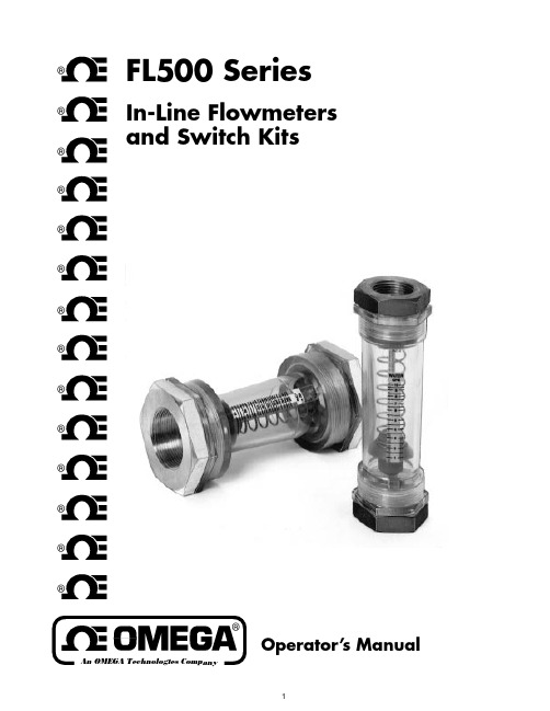
WODA油混水信号器
Omega FL500系列流量计及开关组合说明书

1®®®®®®®®®®®®®®FL500 SeriesOperator’s ManualIn-Line Flowmeters and Switch Kits2Servicing North America:USA:One Omega Drive, Box 4047ISO 9001 CertifiedStamford, CT 06907-0047Tel: (203) 359-1660FAX: (203) 359-7700e-mail:**************Canada:976 BergarLaval (Quebec) H7L 5A1Tel: (514) 856-6928FAX: (514) 856-6886e-mail:****************For immediate technical or application assistance:USA and Canada:Sales Service: 1-800-826-6342 / 1-800-TC-OMEGA SMCustomer Service: 1-800-622-2378 / 1-800-622-BEST SMEngineering Service: 1-800-872-9436 / 1-800-USA-WHEN SM TELEX: 996404 EASYLINK: 62968934 CABLE: OMEGA Mexico and Latin America:Tel: (95) 800-TC-OMEGA SM FAX: (95) 203-359-7807En Espan ˜ol: (203) 359-1660 ext: 2203e-mail:*****************Servicing Europe:Benelux:Postbus 8034, 1180 LA Amstelveen, The Netherlands Tel: (31) 20 6418405FAX: (31) 20 6434643Toll Free in Benelux: 06 0993344e-mail:************Czech Republic:Ostravska 767, 733 01 Karvina Tel: 42 (69) 6311899FAX: 42 (69) 6311114e-mail:***************France:9, rue Denis Papin, 78190 Trappes Tel: 33 0130-621-400FAX: 33 0130-699-120Toll Free in France: 05-4-06342e-mail:****************Germany/Austria:Daimlerstrasse 26, D-75392 Deckenpfronn, GermanyTel: 49 (07056) 3017FAX: 49 (07056) 8540Toll Free in Germany: 0130 11 21 66e-mail:*****************United Kingdom:25 Swannington Road,P.O. Box 7, Omega Drive,ISO 9002 CertifiedBroughton Astley, Leicestershire,Irlam, Manchester,LE9 6TU, England M44 5EX, England Tel: 44 (1455) 285520Tel: 44 (161) 777-6611FAX: 44 (1455) 283912FAX: 44 (161) 777-6622Toll Free in England: 0800-488-488e-mail:************OMEGAnet SMOn-Line Service Internet e-mail http://***************************It is the policy of OMEGA to comply with all worldwide safety and EMC/EMI regulations thatapply. OMEGA is constantly pursuing certification of its products to the European New Approach Directives. OMEGA will add the CE mark to every appropriate device upon certification.The information contained in this document is believed to be correct but OMEGA Engineering, Inc. accepts no liability for any errors it contains, and reserves the right to alter specifications without notice.WARNING: These products are not designed for use in, and should not be used for, patient connected applications.InstallationInlet and outlet ends are marked on the flow meter body,and an arrow on the printed scale indicates flow direction.Insite flow meters can be mounted in any convenient orientation (vertical, horizontal or anything in-between)without affecting performance. The end fittings are con-nected to the plastic body with O-ring sealed straight threads and don't need to be highly torqued to prevent leakage. These fittings accept pipe with tapered threads (NPT). Teflon tape should be used on the pipe threads and standard torques applied, to make leak-free connections.Put your wrench only on the end fitting when piping on.Do not apply wrenches on the plastic body alone when connecting to pipe.Many users find that a disconnect fitting, installed upstream of the flow meter, makes for easier removal of the flow meter, for cleaning internals. Control valves should be installed downstream of the flow meters.Two scales are provided. One for liquid and one for air/nitrogen gasses. Air/nitrogen gas meters are calibrated in SCFM. The air/nitrogen scale is calibrated at 90 PSI pressure and 70o F temperature. If the flow meter is used with air at pressures and/or temperatures that differ from the above, correction factors can be applied to a 90-psi air scale readings to get correct SCFM values. See Tables.High pressure air vented to atmosphere through the Insiteflow meter may result in erratic readings. When used to4For Electric Signallingmeter. As the magnet moves with the piston, its field trips the proximity switch. An adjustment screw changes the actuation point by moving the switch.8 Watts @ 120 VAC/100 VDC. DO NOT EXCEED 300 MILLIAMPS BELOW 26 VAC/26VDC. Switch has three wires: Black for normally open, blue for normally closed, and white for common.NOTE: Switch has a 25% of full scale operating band. Within the band, the switch activates. Above and below the band, the switch deactivates. Thus,one switch can be used as a deviation alarm.Model FL-505, FL-510, and FL-515 flow meters can be equipped with one or two electric switches so that any flowrate within the range of the meter can be made totrigger a signal (or signals).Switch settings are easily adjusted. They are supplied in kit form for installation in the field.Order No. FL-500-R I .Model FL-530, FL-540 and FL-550 require switch kit #FL-500-R2.Each switch kit consists of a ring shaped ceramicmagnet that fits around the flow meter piston, and aproximity switch in a housing that clamps to the body of the flowStep 1. Install the magnet. You must disassemble the flow meter to do this. Follow instructions found under theheading “Maintenance” on page 3. Remove piston from the shaft and place the magnet between piston and spring.Be sure that the piston is installed as in the drawing,and the spring is seated on the magnet and piston.Insert into tube and replace outlet end fittings.Step 2. Install the foam gasket. It has an adhesive on one side, covered with a protective paper. Peel off and press the gasket firmly into place on the switch housing.Step 3. Install the switch housing on the flow meter body.(A) If you are installing only one switch, push thecapscrews through the switch housing tabs, and thread them into the half-collars, as shown. Use the washers provided. The nuts may be discarded.(B) If you are installing two switches, match up the tabs on the two switch housings and push the capscrews through both collar tabs. Put the nuts on the threaded ends of the capscrews and tighten. Use the washers provided. (The half-collars and extra magnet may be discarded.)SWITCH INSTALLATIONNOTE: There is no “wrong orientation” of the switchhousing. If you are installing two switch housings, they can both be oriented the same way, as in the photo, or one “up”and the other “down”. Install to suit your needs in wiring and switch adjustment.SETTING THE SWITCH POINTSWith flow meter installed:Simply adjust the amount of flow to move the piston to the level on the indicator where a switch signal is desired, then turn the switch adjustment screw until switch actuates.(Switch moves toward the adjustment screw head as you turn it clockwise. Use an ohmmeter to determine actua-tion.) Repeat for second switch, if you are using two switches.With flow meter NOT installed:Simulate flow by pushing the eraser-end of a pencil (or a similar tool) through the inlet end of the tube, contacting the float, and moving it against the spring pressure until the knife edge of the float is at the desired reading on the scale. (If your unit has a 1/2 in. pipe fitting, remove it to gain better access.) Then, turn the switch adjustment screw till the switch actuates. (Switch moves toward the adjustment screw head as you turn it clockwise. Use an ohmmeter to determine actuation.) Repeat for a second switch, if you are using two switches.When connecting the switch wires, leave enough lead length (as a pigtail) to allow full travel of the switch.5Direct all warranty and repair requests/inquiries to the OMEGA Customer Service Department. BEFORE RETURNING ANY PRODUCT(S) TO OMEGA, PURCHAS ER MUS T OBTAIN AN AUTHORIZED RETURN (AR) NUMBER FROM OMEGA’S CUS TOMER S ERVICE DEPARTMENT (IN ORDER TO AVOID PROCESSING DELAYS). The assigned AR number should then be marked on the outside of the return package and on any correspondence.The purchaser is responsible for shipping charges, freight, insurance and proper packaging to prevent breakage in transit.FOR WARRANTY RETURNS, please have the following information available BEFORE contacting OMEGA:1.P.O. number under which the product wasPURCHASED,2.Model and serial number of the product underwarranty, and3.Repair instructions and/or specific problemsrelative to the product.FOR NON-WARRANTY REPAIRS,consult OMEGA for current repair charges. Have the following information available BEFORE contacting OMEGA: 1. P.O. number to cover the COSTof the repair,2.Model and serial number of product, and3.Repair instructions and/or specific problemsrelative to the product.OMEGA’s policy is to make running changes, not model changes, whenever an improvement is possible. This affords our customers the latest in technology and engineering.OMEGA is a registered trademark of OMEGA ENGINEERING, INC.© Copyright 1996 OMEGA ENGINEERING, INC. All rights reserved. This document may not be copied, photocopied, reproduced, translated, or reduced to any electronic medium or machine-readable form, in whole or in part, without prior written consent of OMEGA ENGINEERING, INC.67M2473/0796Where Do I Find Everything I Need for Process Measurement and Control?OMEGA…Of Course!TEMPERATUREⅪߜThermocouple, RTD & Thermistor Probes, Connectors, Panels & AssembliesⅪߜWire: Thermocouple, RTD & Thermistor ⅪߜCalibrators & Ice Point ReferencesⅪߜRecorders, Controllers & Process Monitors ⅪߜInfrared PyrometersPRESSURE, STRAIN AND FORCEⅪߜTransducers & Strain Gauges ⅪߜLoad Cells & Pressure Gauges ⅪߜDisplacement Transducers ⅪߜInstrumentation & AccessoriesFLOW/LEVELⅪߜRotameters, Gas Mass Flowmeters & Flow Computers ⅪߜAir Velocity IndicatorsⅪߜTurbine/Paddlewheel Systems ⅪߜTotalizers & Batch ControllerspH/CONDUCTIVITYⅪߜpH Electrodes, Testers & Accessories ⅪߜBenchtop/Laboratory MetersⅪߜControllers, Calibrators, Simulators & Pumps ⅪߜIndustrial pH & Conductivity Equipment DATA ACQUISITIONⅪߜData Acquisition & Engineering Software ⅪߜCommunications-Based Acquisition Systems ⅪߜPlug-in Cards for Apple, IBM & Compatibles ⅪߜDatalogging SystemsⅪߜRecorders, Printers & Plotters HEATERSⅪߜHeating CableⅪߜCartridge & Strip Heaters ⅪߜImmersion & Band Heaters ⅪߜFlexible Heaters ⅪߜLaboratory HeatersENVIRONMENTALMONITORING AND CONTROLⅪߜMetering & Control Instrumentation ⅪߜRefractometers ⅪߜPumps & TubingⅪߜAir, Soil & Water MonitorsⅪߜIndustrial Water & Wastewater TreatmentⅪߜpH, Conductivity & Dissolved Oxygen InstrumentsMANUAL M-2473/0896FL500MAN 200.1M 10/96 8。
油流信号器工作原理

油流信号器工作原理
油流信号器是一种用于检测和报警油流状态的设备,通常应用于液压系统中。
它的工作原理基于油流的压力和流速之间的关系。
以下是油流信号器的工作原理:
1. 油流探针:油流信号器通常由一个或多个油流探针组成,它们被安装在液压系统中的油管路中。
2. 压力传感器:每个油流探针都包含一个压力传感器,用于测量油流周围的压力。
3. 流速计算:油流信号器根据油流探针测量到的压力数据和系统的设计参数,通过内置的算法计算油流的流速。
4. 报警输出:当油流的流速超过或低于设定的阈值时,油流信号器将发出警报信号,可以是声音、光线或电信号,以提醒操作人员注意系统的状态。
需要注意的是,不同型号的油流信号器可能存在细微的差异,但基本的工作原理是相似的。
此外,油流信号器的工作原理还可能受到其他因素的影响,如油的粘度、温度和系统的压力等。
因此,在实际应用中,需要根据具体情况进行调整和校准。
WOD-RG型油混水监控器使用说明书

WOD-RG型油混水监控器 使用说明书哈尔滨瑞格大电机技术有限公司目 录一、概述 (2)二、技术参数 (2)三、接线 (2)四、安装 (3)五、菜单功能及使用方法 (4)Ⅰ 初始画面 (4)Ⅱ 设定菜单 (4)Ⅲ 操作菜单 (5)六、操作说明 (6)1. 菜单说明 (6)2. 显示说明 (7)七、注意事项 (7)一、概述WOD-RG型油混水监测仪器是专门用于测量透平油中含水的百分数,这个数值可以通过LED显示出来。
同时可以测量它所对应的电流值以及报警接点输出,正常情况下0%对应4mA;10%对应电流值为20mA。
二、技术参数供电电源24 VDC ±10%,可选择230 VAC 50 / 60 Hz和220 VDC1或2个,SPDT 30 VDC 2A / 125 VAC 0.6 A,通过电位器可调节范围为2%…5%,设定点通过显示单元可调节范围为满量程测量范围出厂设置为0~10%,如果选配了显示单元,可现场任意设定模拟量输出可选,4~20 mA,最大负载500Ω,最大负载优于0.03 %标准为100 mm,其它长度可选,材质为不锈钢,可选择316 L不锈钢,G1/2”螺纹探头连接工作温度 0..70°C,温度补偿范围0..70°C(如果选配了显示单元)压力 标准产品最大工作压力1.6 MPa,更高压力的探头可定制电气接线 可插拔端子,Pg 11电缆密封;专用电缆接头防护等级IP 65(标准),IP 67可选外壳无显示单元,24 VDC供电80 (L) x 80 (W) x 62 (H)有显示单元或220 VAC/DC供电140 (L) x 80 (W) x 62 (H)三、接线我们使用两个3针插头(C2和C3)和一个4针插头(C1)使您的接线更方便,C1用于电源和模拟量输出,C2和C3用于报警输出,参见图一。
直流供电时1号接线端子为“电源+”,交流供电时为“火线”。
OHS油混水

OHS-II油混水信号器概述油路中混水的危害主要有:①水与油起反应,形成酸、胶质和油泥。
②降低润滑性,加速高应力部件的磨损。
③造成控制阀的粘结或其他低压部位产生气蚀损害;④能腐蚀、锈蚀金属。
因此首先需要加强对油中水含量的监测。
OHS-II油混水信号器主要应用于石油、化工、水电、火电等行业对油质有严格要求的场所。
能够检测出油路中水的含量,使用户可以及时对油进行处理。
功能、工作原理:OHS-II油混水信号器能够对油中混水报警控制,动作点设定连续可调。
OHS-II油混水信号器的工作原理是测量介质在两极板间电容的变化。
当电容两极间油中混水后,两极间的介电常数随之改变。
OHS-II油混水信号器检测到电容的变化量,通过微电路检测出油中含水率的变化。
当油中混水超过一定限度,输出继电器接点报警信号。
继电器的动作值即油混水设定数值。
测量油混水时,可以将传感器直接插入被测介质,但必须保证浸没深度大于150mm。
经特殊标定,OHS-II监控器也可以用于其他液体的含水率报警控制。
技术参数:z 设定范围:2-100%水z 出厂设定:5%水z 工作电源:AC220V或DC24V z 开关量输出:继电器输出,一对常开、常闭接点容量:24VDC ,2A 125AC,0.4A z 功耗:1.2W z 介质温度:0- +100℃环境温度:-20- +50℃z 最大工作压力:6kg/cm2 z 接线盒材料:铝外壳z 护管材料:不锈钢、黄铜z 连接方式:G1/2螺纹安装。
其他方式可选。
z 插入深度:100-700mm内可选。
信号器安装方式:z 顶部安装z 侧部安装z 底部安装信号器接线:OHS-II油混水信号器只需提供直流AC220V或DC24V电源。
为了保证信号器的可靠工作,接线时电源的极性按图示或电路板上的标示接入,不能反接,否则会损坏内部电路。
电路上设有信号指示灯,安装在线路板的正面,打开盒盖后方能看见。
绿色信号灯为电源指示;红色信号灯为工作指示。
原油含水检测分析仪(电磁波)

样本及选型表WOA-1000-A原油含水分析仪WOA-1000-A原油含水分析仪(油田输油,收油,罐车卸油)
原理:
WOA-1000-A原油含水分析仪以电磁波为工作频率,通过发射装置,将恒幅、稳频的电磁波电能发射到含水原油中。
根据油中含水量的不同,介质吸收的波能量不同,探测装置将这个因原油含水量不同而引起吸收电能不同的信号传送到DCS系统或者监测器。
经处理、放大、线性校正后输出一随油中含水量而变化的标准电信号,该信号转换为含水比例。
适用范围:
WOA-1000-A含水分析仪适合于应用于油田原油脱水站、转运站、计量站、卸油站、输油管道及炼油厂等需要计量、监测油中含水量的部位。
尤其适合于原油中、低含水检测,对于化工产品的含水检测同样适用。
技术参数:
监测范围:0~3%,0~10%,0~60%,0~100%等
分辨率:±0.1%;
监测绝对误差:0~3%:
≤±
0.1%;
0~60%:
≤±2%;
0~100%:
≤±3%;;
工作环境温度:
-400
C~800
C;
介质温度:200
C~2400
C;
电源:24VDC;
输出信号:4-20mA;RS485;
防爆等级:
ExdⅡBT4;
消耗功率:15W
特点:
成本低;操作简便,调试简单,零点与满量程;具有温度补偿功能,最高温度可达2400
C;分辨率高,精度高,重复性好;安全,环保,防爆。
维萨拉油中水分仪表比较:MMP330系列与Indigo平台说明书

对比表用于苛刻应用的维萨拉油中水分仪表比较不同之处——可互换的测量探头1.物理测量——探头Indigo 平台的智能探头和 MMT330 的设计概念均以维萨拉久经考验的 HUMICAP®电容型薄膜聚合物传感器技术为基础。
探头的结构、过滤器和安装附件是兼容的,这意味 MMP8 湿度探头可与 HMT338 探头安装在同一过程连接上。
2.信号调节维萨拉 HUMICAP®是一种电容型薄膜聚合物传感器,并且同时附带电阻型温度测量。
必须对这些电量进行适当调节,以获得良好的测量信号。
在 MMT330 平台中,这种调节是在变送器壳体内完成。
这意味着探头是变送器的永久一部分,在不影响测量可靠性的情况下不能将其拆下。
在 Indigo 兼容智能探头中,信号调节发生在探头本体中,因此与数据处理单元无关。
新的 Indigo 平台采用与其前身 MMT330 系列相同的测量技术。
Indigo 平台重要、也是广为期望的特点之一是智能探头的可互换性。
现在智能探头内置了许多传统上位于变送器内部的功能,从而可以进行现场更换和多功能配置。
下图说明了测量仪表的基本功能。
3.模数转换器将经过调节的模拟信号转换为数字格式。
为了更好地展示被测物理量,必须考虑多种因素的影响,例如线性化、压力模型和校准因素等,从而进一步处理好测量信号。
这些用于矿物变压器油的物理量可以是水活度、相对饱和度或计算得出的ppm 等。
Indigo 兼容智能探头中的模数转换发生在探头本体中,因此这些探头可以独立使用,无需配备数据处理单元。
独立探头的测量读数以数字 Modbus RTU 格式提供。
4.HMI ——人机接口您是否需要本地显示屏和用户界面将取决于您的具体应用。
在发生过程故障或需要在本地进行故障排除等情况下,本地用户界面通常是一个有用的工具。
Indigo500 系列和 MMT330 系列变送器均可选择是否配备用户界面。
在 Indigo 平台中,数据处理单元为您提供本地和全图形用户界面选项,以便兼容的智能探头可以在独立模式下运行或连接到数据处理单元。
Omega Universal Wireless 传感器与仪表连接模块 W-23 产品说明书

Universal WirelessTransceiver Module W-23With OMEGA’s universal wireless transceiver modules you can eliminate the wire connection between your sensor and instrument. SPECIFICATIONS Power: 12 to 24 Vdc @ 50 mA Analog Output: 1, non-isolated, retransmission 0 to 5 Vdc, 0 to 10 Vdc Connection: 1.8 m (6') integral analog output cable (included) with stripped wire termination, for both power and output Ambient Operating Range: -10 to 70°C (14 to 158°F), 0 to 95% RH (non-condensing)Radio Receiver Frequency (RF): 2.4 GHz Enclosure: ABS (plastic)Dimensions: 76 L x 32 W x 26 mm H (3 x 1.25 x 1")* Specify analog output signal: “V1” for 0 to 5 Vdc or “V2” for 0 to 10 Vdc.Ordering Example: UWTC-REC6-V1, wireless transceiver/converter with 0 to 5 Vdc analog output.E Y R e c D a t a L o g g e r !All models shown smaller than actual size.UWTC-2 universal wireless thermocouple connector.Simply connect this transceiver to the analog input on your instrument and you’ll be able to receive wireless measurements from many different wireless sensors including OMEGA’s wireless thermocouple and RTD connectors, pH, infrared temperature, relative humidity, process input transmitters and our NB9 Series of industrial wireless probe/transmitters assemblies. A dd Wireless Capability to Any Standard Process Input Instrument Analog Output Signal E asily Connect to Panel Meters , Controllers, PLCs, Chart Recorders and Data Loggers S imple, Single Channel Operation I ncludes Mounting Bracket and 1.8 m (6') Integral Cable P owered From Host Instrument or External Power Supply C ompatible with All OMEGA UW Series Wireless Transmitters RoHS 2 Compliant DP24-E, process indicator, sold separately.PATENT PENDING UWTC-REC6 shown actual size. 1.8 m (6') Up to 120 m (400') wirelessProduct Discontinued。
油中含水传感器工作原理

油中含水传感器工作原理以油中含水传感器工作原理为标题,我们来探讨一下这个感应器的工作原理。
油中含水传感器是一种用于检测油中水分含量的装置,它在许多领域中都有广泛的应用,例如石油工业、化工工业和汽车工业等。
它可以准确地测量油中的水分含量,并及时发出警报,以避免设备故障或损坏。
油中含水传感器的工作原理主要基于电化学原理。
它通常由两个主要部分组成:电极和电路。
电极负责接触油中的水分,并将其转化为电信号,而电路则负责将电信号转化为可读取的数据。
我们来看一下电极的作用。
电极通常由导电材料制成,例如铜、银或铂等。
当电极接触到油中的水分时,由于水分中含有大量的离子,电极与水分之间会形成一个微弱的电流。
这个微弱的电流可以被电路感应和测量。
接下来,我们来了解一下电路的作用。
电路通常由一个感应器和一个测量设备组成。
感应器用于接收和放大电极产生的微弱电流信号,并将其转化为可测量的电压信号。
测量设备则用于读取和显示电压信号,并将其转化为油中的水分含量。
在电路中,感应器起着至关重要的作用。
感应器通常由一个或多个放大器组成,它们可以放大电极产生的微弱电流信号,以便更容易测量和读取。
感应器还可以根据需要进行调整和校准,以确保测量的准确性和稳定性。
除了电极和电路,油中含水传感器还可能包含其他附件和功能,以满足特定的需求。
例如,一些传感器可能配备了温度传感器,以测量油的温度,并根据温度对水分含量进行校正。
另外,一些传感器还可能具有报警功能,当油中的水分超过一定的阈值时,会发出警报,以提醒操作人员采取相应的措施。
总的来说,油中含水传感器的工作原理是基于电化学原理的。
通过电极将油中的水分转化为微弱的电流信号,然后通过电路感应和测量这个电流信号,并将其转化为可读取的数据。
这个过程需要精确的感应器和测量设备,以确保测量结果的准确性和稳定性。
油中含水传感器在许多领域中都起着重要的作用,帮助我们监测和控制油中的水分含量,以保证设备的正常运行和延长设备的使用寿命。
- 1、下载文档前请自行甄别文档内容的完整性,平台不提供额外的编辑、内容补充、找答案等附加服务。
- 2、"仅部分预览"的文档,不可在线预览部分如存在完整性等问题,可反馈申请退款(可完整预览的文档不适用该条件!)。
- 3、如文档侵犯您的权益,请联系客服反馈,我们会尽快为您处理(人工客服工作时间:9:00-18:30)。
图1工作原理示意图主要技术参数
测量范围:0…5%~10%含水量
工作电压:24VDC
220V AC/DC
最大功耗: 1.5W(24VDC)
3W(220VAC/DC)输出方式:4-20mA及2组SPST
连接方式:螺纹或法兰
安装方式:侧装式:110mm
顶装式:110~3000mm 探头材质:不锈钢/黄铜
图2结构部件图
图3尺寸图
四.端子分配及电气接线图
1、DC24V接线图
图4端子分配及电气连接图
图5端子分配及电气连接图
接电源“L”,2接电源“N”;
4-20mA输出“+”,8接4-20mA输出“-”;
切勿将电源与输出线接错,以防烧坏变送器;
对应菜单LDIR,COM2和NO2对应菜单HDIR
结构所示,请按照以下方法安装:
通过连接螺纹将控制器安装在测量口位置。
安装顶装式时,如果探头达不到被测介质的底部,则调节图2示的调节螺母,使探头达到测量容器底部;在测量旋转油盆等高速转动容器油混水含量时,为防止旋转时摩擦损坏控制器,需将控制器上5mm。
打开接线盒后盖,依据图4及图5进行连线。
整理、固定引出的电缆,并装上上盖。
安装时,不要直接用手大力旋转上盖以紧固控制器,应用扳手扳动连接螺纹上方的六方螺母紧固。
控制器应当安装在油槽或油罐的侧部或底部,探头插入油中的深度应至少为
”按键,
同时按“””键。
,”键右移小数点。
设置方法同。
”键进入报警开关设置,显示当前设置值
,表示以下的设置报警参数生效。
不管是何种
,表示数值由低向高变化报警。
,表示数值由高向低变化报警。
,。
