GW智能电机保护控制器选型手册介绍
电机智能保护器配置手册说明书

How to configure, monitor, and control Motor Insight via Modbus, DeviceNet, and PROFIBUSApplicationMotor Insight T is an advanced motor protective relay with thermal motor overload, supply,and load protection; configurable ground fault detection; power monitoring; an intuitive user interface; and optional communications. The optional communications allow for remote control and reset of faults, and remote monitoring of numerous operating and configuration parameters. The communication modules also include inputs that can be usedto bring the status of sensors or switches backto the system controller, as well as outputs to control the contactor or turn on pilot lights.OverviewThe industrial networks supported by the Motor Insight relay are all open networks. This means that there are many software tools already available that can be used to configure the device over these networks. Each of the supported networks will be discussed in this document, including suggestions for various configuration tools, many of which are free downloads from the Internet. In many cases, the network tools supplied by the manufacturerof the network master can be used to configure any device on that network.Overview of Modbus T, DeviceNet E and PROFIBUS TFor most applications, the Motor Insight relay parameters can be easily configured using its intuitive user interface. Then, the communication network master can be used to control and monitor the device during operation. This network master reads status information from each slave device and writes control information. The communication interface modules forMotor Insight allow control for the following:1. Remote reset of a fault2. Remote trip3. Control of on-board field outputs Numerous parameters are available to be monitored from Motor Insight, including:1. Device status bits2. rms current IA3. rms current IB4. rms current IC5. rms current average6. rms voltage VAB7. rms voltage VBC8. rms voltage VCA9. rms voltage average10. Total kW11. Voltage unbalance percent12. Current percent13. Apparent power factor14. Residual ground current deciamps15. Frequency16. Overload thermal pile17. Trip reason18. Overload status19. Error code20. Field inputsThe following is a discussion concerning the third-party software tools available for the open networks supported by Motor Insight. ModbusMotor Insight supports both Modbus RTU and Modbus ASCII modes, as well as baud rates from 9600 to 115.2K baud. It will communicate with any Modbus master.The unique aspect of Modbus is that special configuration tools are typically not necessaryas they are with many other industrial networks. The reason is that Modbus requires Modbus Data Register addresses for all parameters in all Modbus devices. This allows a Modbus master to easily read and write data to a Modbus slave device for configuration, control, and monitoring purposes. Motor Insight is no different. It has assigned a Modbus Data Address to all available parameters. This information is publishedin the Motor Insight overload and monitoring relays user manual, publication MN04209001E.Eaton Corporation Electrical Sector1111 Superior Ave. Cleveland, OH 44114United States877-ETN-CARE (877-386-2273) © 2010 Eaton CorporationAll Rights ReservedPrinted in USAPublication No. AP04209004E / Z9775 August 2010PowerChain Management is a registered trademark of Eaton Corporation.All other trademarks are property of their respective owners.Application Paper AP04209004E Effective August 2010How to configure, monitor, and control Motor Insight via Modbus, DeviceNet,and PROFIBUSIf a third-party Modbus software package is desired to configureor verify the configuration or operation of Motor Insight, there are numerous software tools available. Many of these tools are free downloads, such as ModScan. Others can be found by simply searching the Web for Modbus Software Tools.Eaton has a line of electronic operator interface devices called HM i.A program for a 4-inch HM i is available as a free download from /motorinsight or via this direct link. This program communicates via Modbus to multiple Motor Insight devices. It contains screens for configuring, monitoring, and controlling upto 16 Motor Insights from a single HM i. To obtain the HM i software needed to download the program to an HM i, visit / electrical. Then, click the “Tools & Downloads” link. Next, select “Software Downloads.” On the next page, under the Products drop-down, select “Operator Interface...” and then select “HM i Operator Interface Configuration Software.” Also note that the HM i software allows for changing the HM i program so it can be downloaded to any size HM i: 4-, 6-, 8-, or 10-inch unit.Another source of available Modbus tools can be found on the official Modbus Web site: .DeviceNetUnlike Modbus, where all parameters in a device have a data address assigned to them, DeviceNet slave devices use input and output assemblies. Each input assembly will include the same status bits indicating operational status of the device. The various input assemblies differ by the additional data that can be monitored with each. The Motor Insight relay has five different input assemblies. Two of these input assemblies allow the user to select the parameters to monitor. The various output assemblies are for control. They provide the ability to reset faults, trip the overload, and turn the outputs on-board the DeviceNet module on and off. DeviceNet is an open network that requires a software tool to configure slave devices and to map their data into the scan list of the master. The manufacturer of the DeviceNet master will provide a software tool to map slave devices into the scan list of the master so the system controller can control and monitor each Motor Insight. Motor Insight contains an intuitive user interface for configuration, but when on a DeviceNet network, it can be configured by any third-party DeviceNet commissioning tool as well. The DeviceNet specification requires that all DeviceNet products have an eds file (electronic data sheet). This file is a text file that is used to uniquely define each parameter in the device. DeviceNet commissioning tools are designed with the ability to import eds files for any valid DeviceNet slave device. The software tool can then be used to configure the device. There are two eds files and an icon file available for Motor Insight. They may be downloaded from/motorinsight. These files can then be imported into any valid DeviceNet commissioning software, such as:1. Eaton’s CHStudio E2. Eaton’s ELCSoft (DNET CONFIG Tool)3. Rockwell’s RSNetWorx E for DeviceNetCHStudio is a free download from the Eaton Web site; searchfor CHStudio and download the software and activation code.It can be used to configure any DeviceNet slave device, but notthe network master.ELCSoft is the programming software for the Eaton PLC line called ELC. This PLC line includes a complete DeviceNet master, the ELC-CODNETM module. The commissioning software is included in the ELCSoft programming software. It can configure any DeviceNet slave device by importing the eds file for the device and can fully configure the ELC-CODNETM DeviceNet master module.The manufacturer of the network master typically supplies the software tools needed to configure the master. RSNetWorxfor DeviceNet can be purchased from Rockwell or a Rockwell distributor. Motor Insight eds files can be imported into RSNetWorx for DeviceNet, allowing the software to configurethe Motor Insight and a Rockwell DeviceNet master.Once all slave devices on a DeviceNet network have been configured and mapped into the DeviceNet master’s scan list, the master will continuously poll the slave devices, like the Motor Insight, writing control data to them and monitoring various parameters. Motor Insight has more data available to monitor than any other overload relay of its type. This information is published in the Motor Insight overload and monitoring relay user manual, MN04209001E.Another source of available DeviceNet tools can be found on the official DeviceNet Web site: .PROFIBUSPROFIBUS is very similar to DeviceNet in that the network configuration tools are typically supplied by the manufacturer of the PROFIBUS master. There is also a file for PROFIBUS similar to the eds file for DeviceNet, called a GSD file. All valid PROFIBUS slave devices must have a GSD file. This file is imported into the PROFIBUS commissioning tool or the programming software, allowing the software to configure the device and map its I/O data so the PROFIBUS master can poll the slave devices for control and monitoring purposes. These PROFIBUS tools are supplied bythe manufacturer of the PROFIBUS master. The GSD file may be downloaded from /motorinsight. This file can then be imported into any valid PROFIBUS software tool, such as Siemen’s SIMATIC Software. Other PROFIBUS network product vendors are Woodhead Connectivity, Bihl+Wiedemann GmbH and PROCENTEC. Another source of available PROFIBUS tools can be found on the official PROFIBUS Trade Organization Web site: /.Supporting documentationMotor Insight User Manual MN04209001E Motor Insight DeviceNet Instructional Leaflet IL04209005EMotor Insight Modbus Instructional Leaflet IL04209004EMotor Insight PROFIBUS Instructional Leaflet IL0420900XEELC System Manual MN05003003EELC-CODNETM Instructional Leaflet IL05001003EHM i User manual MN04802014EAdditional helpIn the event that additional help is needed, please contact the Technical Resource Center at 1-877-ETN-CARE (386-2273).。
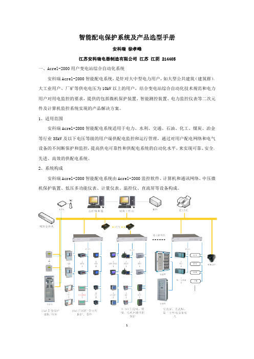
智能配电保护系统及产品选型手册
时间元件:延时时间 2s 内误差≤40ms;延时时间大于 2s,误差≤(1%)整定值±40ms。 绝缘电阻:>100MΩ,500Vdc 介质强度:回路和地之间,独立回路之间:工频耐压 2KV 冲击电压:±5KV(1.2/50μs,0.5J) 符合标准:DLT 587-2007 微机继电保护装置运行管理规程
母联保 护及备
自投
√
√ ■
厂用变
110kV 及以下电压等级、容量为 6300kVA
电容器
PT 监测 PT 并列
压器
及以上的变压器
√
√
√
√
√
√
√
√
√
√
√
√
√
√
√
√
√
√
√
√
√
√
√
√
■
■
■
■
■
■
■
■
Modbus-RTU/IEC60870-5-103
√
√
√
√
√
√
√
√
√
IRIG-B 对时
■
■
■
■
■
■
3)AM6 背部接线 ► AM6-D2 微机变压器差动保护
► AM6-T 微机变压器后备保护
AM6-D2 背部端子图
8
AM6-T 背部端子图 ► AM6-FD 微机变压器非电量保护 装置由五块插件组成: 方 案 一 : 一 个 非 电 量 输 入 插 件 (2X) , 一 个 非 电 量 输 出 插 件 (1X) , 三 个 操 作 回 路 插 件 (3X,4X,5X)。 方案二:两个非电量输入插件(2X,3X),一个非电量输出插件(1X),二个操作回路插件 (4X,5X)。 方案三:五个操作回路插件(1X,2X,3X,4X,5X)。 非电量输入插件原理图:
GW-A91智能操控装置说明书(一)

GW-A91系列开关柜综合操显装置使用说明书XX冠网电力科技XX所有不得复制产品概述GW-A91产品是根据当前中压系统开关柜技术发展而设计开发的一种新型的模块化、智能型的操作测量显示装置。
该系列产品集主回路模拟指示、带电指示与闭锁、验电功能、温湿度数字实时显示、自动加热除湿控制、自动排风降温控制、断路器分合闸状态指示、储能、接地开关指示、手车位置指示、智能防误语音提示、人体感应报警语音警示、回路电流、电压、频率、功率、电能、断路器进线出线母排温度测量显示、故障记录查询、时钟指示、手动自动储能选择、远程就地切换、分闸合闸操作以与RS 485通讯接口等功能于一体,可根据需要选配。
该产品以一体化布局配套装备于开关柜,将简化开关柜的面板结构设计,美化开关柜的面板布局,完善开关状态的指示功能和安全性能。
该系列可用于3~40KV户内的开关柜、适用于中置柜、手车柜、固定柜、环网柜等多种开关柜。
符合IEC255-22标准。
一、主要技术特性1. 使用环境a) 温度:周围空气温度上限为+65℃,且24h内的平均值不超过+35℃;周围空气温度下限为-40℃。
b) 湿度:大气相对湿度在周围空气温度为+40℃时不超过50%RH ,在较低的温度下可以有较高的相对湿度,例如20℃时可达到95%RH。
对由于温度变化产品表面上偶尔产生的凝露已采取特殊措施。
c) 海拔:安装地点的海拔不超过2000m。
2. 安装a) 与垂直面的安装倾斜度不超过5度;b) 应安装在无显著振动和冲击的地方。
3. 开孔尺寸:220mm×165mm4.污染等级:污染等级为“污染等级3”。
5. 防护等级防护等级为:IP20。
6 多功能表电能计量起动在额定电压、参比频率与功率因数为1的条件下,负载电流为0.001Ib(0.2级)、0.001Ib(0.5级)、0.004Ib(1级)、0.005 Ib(2级)电能表应能起动并连续计量电能。
7 时钟准确度:日误差≤0.5s(23℃)。
华光电机智能保护器配套CT选型说明
电机智能保护器配置电流互感器选型说明杭州华光电气有限公司HANGZHOU CHINA-SHINE ELECTRIC CO.,LTD目录1.一体式三相电流互感器 (1)2.单相式电流互感器 (2)3.CSP系列电机智保器互感器选型对照表 (4)1)电机容量与5A电流互感器对照选型表 (4)2)电机容量与1A电流互感器对照选型表 (5)4.CDP-M10系列电机智保器互感器选型对照表 (7)1)电机容量与5A电流互感器对照选型表 (7)2)电机容量与1A电流互感器对照选型表 (8)5.CDP-M20、 CDP-M22系列电机智保器互感器选型对照表 (9)6.电机智保器附加功能说明 (11)1.一体式三相电流互感器型号描述SBH0.66-20 I □/□额定二次电流 ,1A额定一次电流φ20圆孔结构额定电压:0.66kV分类:三相式电流互感器举例:SBH0.66-20 I 、100A/1A表示:额定电压为660V的封闭式的三相电流互感器,变比为100/1 。
外形尺寸图如下:2.单相式电流互感器型号描述BH0.66-□□□/□额定二次电流,5A或1A额定一次电流结构类型:例:I型(方圆孔)、II型(方孔)孔径大小:例80:孔径为80mm宽度额定电压:0.66kV分类:单相式电流互感器举例:BH0.66-40 I 、150A/1A表示:额定电压为660V的封闭式的单相电流互感器,母排宽度为40mm,方圆孔结构,变比为150/1 。
外形尺寸图如下:30I型:40I型:60II型:100II型:3.CSP系列电机智保器互感器选型对照表1)电机容量与5A电流互感器对照选型表注:电流互感器为单相式,一只电机智能保护器对应配置三只单相式电流互感器。
2)电机容量与1A电流互感器对照选型表注:一只电机智能保护器对应配置一只三相一体式电流互感器或三只单相式电流互感器。
4.CDP-M10系列电机智保器互感器选型对照表1)电机容量与5A电流互感器对照选型表注:电流互感器为单相式,一只电机智能保护器对应配置三只单相式电流互感器。
GW3-GL系列智能型超低温专用万能式断路器

4000
水平
120 80 100 65 264/0.2 176/0.2 65 50 25~30 60~70 4~5 ● ● ● 10000 5000 15000 30000 垂直
水平
垂直
●
●
●
●
●
●
H×W×L
435×435× 421
435×550× 494
435×550×421
—
400×422×323
N极额定电流 IN (A)
额定极限短路分断能力 Icu(kA)(有效值)
AC400V AC690V
额定运行短路分断能力 Ics(kA)(有效值)
AC400V AC690V
额定短路接通能力 Icm(kA)(峰值)
AC400V AC690V
额定短时耐受电流 (1s) Icw(kA)(有效值)
手动和电动操作机构依次排在其前面形成 各自独立的单元,维修更换方便。
GW3系列抽屉式断路器组成
二次回路接线端子(静) 抽屉座
摇手柄 安全隔板
二次回路接线端子(动) 辅助触头 分励脱扣器 欠电压脱扣器 合闸电磁铁 操作机构
电动操作机构
智能控制器
北京人民电器厂有限公司 4
结构特点
2
触头系统
安装在绝缘小室内,每相触头系统采用片状并联结构,降低了电动斥力,保证了断路器的高分断能力。
路器
代 2000A 100kA 号 3200A 120kA
3:3P 4:4P
型发电 专用 断路器
6300A 120kA
额定电流(A)
2000
630 800 1000 1250 1600 2000
3200
2000 2500 3200 4000
Eaton Moeller PKZM0电机保护电路保护器产品说明说明书

Eaton 229830Eaton Moeller® series PKZM0 Motor-protective circuit-breaker, 0.09 kW, 0.25 - 0.4 A, Screw terminals on feed side/spring-cage terminals on output sideGeneral specificationsEaton Moeller® series PKZM0 Motor-protective circuit-breaker229830401508229830276 mm 93 mm 45 mm 0.244 kg CE MarkedCSA Std. C22.2 No. 14 IEC 60947-4-1 UL 508 VDECSA Class No.: 3211-05 IEC/EN 60947 ULUL File No.: E36332 IEC/EN 60947-4-1 CECSA File No.: 165628 CSA-C22.2 No. 60947-4-1-14 UL 60947-4-1UL Category Control No.: NLRV CSA VDE 0660This item can only be ordered untilPKZM0-0,4-SCProduct NameCatalog Number EANProduct Length/Depth Product Height Product Width Product Weight Compliances CertificationsCatalog NotesModel Code0.4 A1 x (1 - 6) mm², ferrule to DIN 46228, Screw terminals2 x (1 - 6) mm², ferrule to DIN 46228, Screw terminalsIs the panel builder's responsibility. The specifications for the switchgear must be observed.25 °C0.09 kW65 kA, 480 Y/277 V, SCCR (UL/CSA)50 kA, 600 Y/347 V, SCCR (UL/CSA)Accessories required BK25/3-PKZ0-E65 kA, 240 V, SCCR (UL/CSA)Meets the product standard's requirements.Is the panel builder's responsibility. The specifications for the switchgear must be observed.Does not apply, since the entire switchgear needs to be evaluated.0.4 A, AC-3 up to 690 V0.4 A (3 contacts in series), DC-5 up to 250V10 mm40 °C150 kAMeets the product standard's requirements.eaton-manual-motor-starters-characteristic-characteristic-curve-008.eps eaton-manual-motor-starters-characteristic-characteristic-curve-003.epsDA-DC-00004892.pdfDA-DC-00004921.pdfeaton-manual-motor-starters-pkz-dimensions-002.epseaton-manual-motor-starters-pkz-dimensions-003.epseaton-manual-motor-starters-pkz-dimensions.epseaton-manual-motor-starters-pkzm0-3d-drawing-008.epseaton-manual-motor-starters-pkzm0-3d-drawing-003.epsETN.PKZM0-0,4-SCIL122023ZUIL03402034ZIL03407011Zpkzm0_scpkzm0_sc.stpeaton-manual-motor-starters-transformer-pkzm0-wiring-diagram.epsRated operational current for specified heat dissipation (In) Terminal capacity (flexible with ferrule)10.11 Short-circuit ratingAmbient operating temperature (enclosed) - minRated operational power at AC-3, 380/400 V, 50 HzShort-circuit current rating (type E)10.4 Clearances and creepage distances10.12 Electromagnetic compatibility10.2.5 LiftingSwitching capacityStripping length (main cable)Ambient operating temperature (enclosed) - maxRated short-circuit breaking capacity Icu at 400 V AC 10.2.3.1 Verification of thermal stability of enclosures Ambient storage temperature - min Characteristic curve Declarations of conformity DisegnieCAD modelGuide utenteIstruzioni di installazione mCAD modelSchemi di cablaggio40 °CAdjustment range undelayed short-circuit release - max6.2 A10.8 Connections for external conductorsIs the panel builder's responsibility.ProtectionFinger and back-of-hand proof, Protection against direct contact when actuated from front (EN 50274)Actuator typeTurn buttonRated operational power at AC-3, 440 V, 50 Hz0.12 kWAmbient operating temperature - max55 °CRated operational power at AC-3, 220/230 V, 50 Hz0.06 kWClimatic proofingDamp heat, cyclic, to IEC 60068-2-30Damp heat, constant, to IEC 60068-2-78Device constructionBuilt-in device fixed built-in techniqueFeaturesPhase-failure sensitivity (according to IEC/EN 60947-4-1, VDE 0660 Part 102)Lifespan, electrical100,000 operations (at 400V, AC-3)Static heat dissipation, non-current-dependent Pvs0 WElectrical connection type of main circuitScrew connection10.9.3 Impulse withstand voltageIs the panel builder's responsibility.Number of polesThree-poleAmbient operating temperature - min-25 °C10.6 Incorporation of switching devices and componentsDoes not apply, since the entire switchgear needs to beevaluated.10.5 Protection against electric shockDoes not apply, since the entire switchgear needs to be evaluated.Mounting positionCan be snapped on to IEC/EN 60715 top-hat rail with 7.5 or15 mm height.Rated uninterrupted current (Iu)0.4 ATripping characteristicOverload trigger: tripping class 10 AShort-circuit release6.2 A, Irm, Setting range max.± 20% tolerance, Trip blocksBasic device fixed 15.5 x Iu, Trip Blocks10.13 Mechanical functionThe device meets the requirements, provided the information in the instruction leaflet (IL) is observed.Terminal capacity (flexible)2 x (0.75 - 2.5) mm², ferrule to DIN 46228, Spring-loaded terminals1 x (0.75 - 2.5) mm², ferrule to DIN 46228, Spring-loaded terminals10.2.6 Mechanical impactDoes not apply, since the entire switchgear needs to be evaluated.10.9.4 Testing of enclosures made of insulating materialIs the panel builder's responsibility.10.3 Degree of protection of assembliesDoes not apply, since the entire switchgear needs to be evaluated.Heat dissipation per pole, current-dependent Pvid1.74 WOperating frequency40 Operations/hProduct categoryMotor protective circuit breakerShort-circuit current rating (group protection)600 A, 600 V High Fault, max. CB, SCCR (UL/CSA)50 kA, 600 V High Fault, Fuse, SCCR (UL/CSA)600 A, 600 V High Fault, max. Fuse, SCCR (UL/CSA)50 kA, 600 V High Fault, CB, SCCR (UL/CSA)Overload release current setting - min0.25 ARated operational power at AC-3, 690 V, 50 Hz0.18 kWEquipment heat dissipation, current-dependent Pvid5.22 WHeat dissipation capacity Pdiss0 WRated operational current (Ie)0.4 ASuitable forAlso motors with efficiency class IE3Branch circuit: Manual type E if used with terminal, or suitable for group installations, (UL/CSA)Internal resistance10500 mΩTemperature compensation-25 - 55 °C, Operating range≤ 0.25 %/K, residual error for T > 40°-5 - 40 °C to IEC/EN 60947, VDE 0660Terminal capacity (solid)1 x (0.75 - 2.5) mm², Spring-loaded terminals2 x (0.75 - 2.5) mm², Spring-loaded terminalsRated frequency - min50 HzShort-circuit current60 kA DC, up to 250 V DC, Main conducting pathsPower loss5.22 W10.2.3.2 Verification of resistance of insulating materials to normal heatMeets the product standard's requirements.10.2.3.3 Resist. of insul. mat. to abnormal heat/fire by internal elect. effectsMeets the product standard's requirements.Lifespan, mechanical100,000 Operations (Main conducting paths)Terminal capacity (solid/stranded AWG)18 - 14Overload release current setting - max0.4 A10.9.2 Power-frequency electric strengthIs the panel builder's responsibility.Overvoltage categoryIIIDegree of protectionTerminals: IP00IP20Rated frequency - max60 HzSwitch off techniqueThermomagneticAmbient storage temperature - max80 °CAdjustment range undelayed short-circuit release - min6.2 APollution degree310.7 Internal electrical circuits and connectionsIs the panel builder's responsibility.Rated impulse withstand voltage (Uimp)6000 V ACConnectionScrew terminals on feed sideSpring-cage terminals on output side10.10 Temperature riseThe panel builder is responsible for the temperature rise calculation. Eaton will provide heat dissipation data for the devices.FunctionsMotor protectionPhase failure sensitiveTightening torque1.7 Nm, Screw terminals, Main cable1 Nm, Screw terminals, Control circuit cablesEaton Corporation plc Eaton House30 Pembroke Road Dublin 4, Ireland © 2023 Eaton. Tutti i diritti riservati. Eaton is a registered trademark.All other trademarks areproperty of their respectiveowners./socialmedia690 VATEX dust-ex-protection, PTB 10, ATEX 3013, Ex II(2) GD Meets the product standard's requirements.Meets the product standard's requirements.Meets the product standard's requirements.0.12 kW 25 g, Mechanical, according to IEC/EN 60068-2-27, Half-sinusoidal shock 10 ms690 V Max. 2000 mRated operational voltage (Ue) - min Explosion safety category for dust10.2.2 Corrosion resistance10.2.4 Resistance to ultra-violet (UV) radiation 10.2.7 InscriptionsRated operational power at AC-3, 500 V, 50 Hz Shock resistanceRated operational voltage (Ue) - max Altitude。
智能低压电动机保护器选型手册
从而实现电动机的不同起动方式(如 Y- △转换起动、正反转控制,自耦降压起动等)。
2、温度保护的测量范围:PTC 热电阻 1kΩ~10kΩ。
3、对于无显示要求的客户,必须在一批定单中订购一个 90FL 显示单元,作为调试使用。
5.2.2 技术指标
技术参数 保护器辅助电源 电机额定工作电压
电动机额定工作电流
1
选配保 护器
额定电 流 2 2
整定电 流范围
(A)
0.40-2.00 0.40-2.00
电动机 额定 功率 (kW)
30 37
电动机 额定 电流 (A) 57 69
选配保 护器额 定电流
100 100
整定电 流范围
(A)
25-100 25-100
8
0.55
1.5
2
0.40-2.00
45
81
100
95 96
97
COM2 起动 1 起动 2 报警
脱扣
25 26 27
A
B COM1
RS485 通讯
35 36
AO+ AO-
4-20mA 模拟量输出
40 41
32 33
I0* I0
零序电流输入
T1 T2
热电阻输入
开关量输入
注:12 路 DI 在保护模式下,只作为开关量输入使用。
5.3 ARD3 系列智能电动机保护器
352
800
15
28.5
100
25-100
220
388
800
远程显示模块。根据需要选配 ARD3 的功能模块或附件,与接触器、电动机起动器等电器元
件构成电动机控制保护单元,有远程自动控制、现场直接控制、面板指示、信号报警、现场
GW系列电动机保护使用说明书
广州格务电气自动化设备有限公司
广州格务电气自动化设备有限公司
GW2300
广州格务电气自动化设备有限公司
广州格务电气自动化设备有限公司
广州格务电气自动化设备有限公司
广州格务电气自动化设备有限公司
GW
GW
GW
GW GW
GW
GW
广州格务电气自动化设备有限公司
GW
广州格务电气自动化设备有限公司
GW2301(2)T GW2301(2)T
GW2301(2)T
GW2301(2)T
GW2301(2)T
GW2301(2)T GW2301(2)T
GW2301(2)T
GW2301(2)T
GW2301(2)T
GW2301T
GW2302T
广州格务电气自动化设备有限公司
GW2301T/GW2302T/GW2302T-F
GW2301面版
GW2302面版
广州格务电气自动化设备有限公司
GW2301T/GW2302T/GW2302T-F GW2301T/GW2302T/GW2302T-F
GW2301(2)T
GW2301(2)T
GW2301(2)T
GW2301(2)T
GW2301(2)T GW2301(2)T GW2301(2)T
GW2301L/GW2302L/GW2302L-F GW2301L/GW2302L/GW2302L-F
GW2301L/GW2302L
GW2301(2)L
GW2301(2)L
GW2301(2)L
GW2301(2)L GW2301(2)L
GW2301(2)L GW2301(2)L
GW2301(2)L
北京人民GW3万能式断路器 - 复件
■ 用途及适用范围……………………………………………… 2 ■ 断路器符合标准……………………………………………… 2 ■ 型号及演示含义……………………………………………… 2 ■ 正常工作和安装条件………………………………………… 2
■ GW3-2000~6300 万能断路器主要零部件分解图………… 3 ■ 固定式断路器面板构成……………………………………… 4 ■ 抽屉式断路器面板构成……………………………………… 4
企业先后获得“北京市守信企业”、“北京市质量管理优秀 企业”等称号,并被中国质检协会评定为“质量兴企、争创名牌 示范单位”,“固安祥”商标被评为“北京市著名商标”和“低 压断路器”产品被评为“北京名牌产品”。
辉煌的业绩:有超过1500万台直流产品和5000万台交流产品 在全国各地电厂、变电站、风电场、光伏电站、工矿企业、政治 性工程等可靠运行,特别是祖国五十周年大庆天安门供电工程、 2008年北京奥运会、首都机场三号航站楼等重大项目和新能源领
●断路器应按本说明书安装要求安 装。断路器的垂直倾斜度不超过5°,断路 器主电路及欠电压脱扣器线圈、电源变压 器初级线圈的安装类别为IV,其余辅助电
路、控制电路安装类别为Ⅲ。 ●污染等级为3级。 ●断路器一般采取敞开式安装,防
护等级可以达到IP30;断路器安装在柜 体小室内,加装门框,防护等级可以达到 IP40;安装在柜体小室内并加装门框及透 明罩,防护等级可以达到IP54。
■ 强制灭弧装置 [ 发明专利] ………………………………… 5 ■ 高绝缘性 [ 发明专利] ……………………………………… 5
■ 主要技术参数及性能指标…………………………………… 6
■ 控制器功能及面板说明……………………………………… 8 ■ 智能控制器保护特性曲线………………………………… 10 ■ 过电流保护特性…………………………………………… 12 ■ 接地故障保护特性………………………………………… 12 ■ 负载监控功能……………………………………………… 13 ■ 断路器保护特性表………………………………………… 13 ■ 出厂整定值………………………………………………… 14
天正 TGW1N 系列万能式断路器 说明书
001234512101187916远程操作锁类指示与防护附件控制附件分励脱扣器挂锁三位置电气指示N 相外接互感器闭合电磁铁钥匙锁辅助开关漏电互感器欠电压脱扣器门联锁门框接地电流互感器欠电压延时脱扣器三位置锁相间隔板电源模块电动机操作机构机械联锁继电器模块TGW1N 系列万能式断路器配电电器0021314151617181920万能式断路器分励脱扣器闭合电磁铁欠电压脱扣器欠电压延时脱扣器电动机操作机构挂锁钥匙锁门联锁缆绳联锁辅助开关门框相间隔板接地电流互感器漏电互感器N 相外接互感器电源模块继电器模块123456789101314151617181920连杆联锁11三位置锁12003TGW1N 系列万能式断路器(以下简称断路器),适用于交流50/60Hz,额定电压AC380V~AC690V,额定电流200A~6300A 的配电网络中,用来分配电能和保护线路及电源设备免受过载、短路、欠电压、单相接地或剩余电流等故障的危害。
该断路器具有可通信及智能化保护功能,能提高供电可靠性,避免不必要的停电。
其优异的分断性能,及高质量的产品品质可全面替代市面上的DW45产品。
国际标准及认证:3C CE CB 符合标准:GB/T14048.2 IEC/EN60947-2TGW1N 系列万能式断路器1 产品概述2 产品命名规则TG W 1N 2000 H / 3P □ □ □ □ □ □ □ □ □ □ 特殊要求:缺省:无 杠杆联锁 缆绳联锁 一锁一钥匙 两锁一钥匙 三锁一钥匙 加长母排 电气三位置指示门连锁 双电源控制器 按钮锁 ……应用场合:缺省:无高原 湿热 环保 盐雾 低温辅助触头代号:缺省:四开四闭选配(需注明):五开五闭 六开六闭欠压脱扣器电压:缺省:无 AC220V/230V AC380V/400V 当欠压电压与控制回路电压不一致时,需要注明欠压延时:1s 控制回路电压:AC220V/230V AC380V/400V DC220V DC110V 如有多种电压等级特殊说明中说明控制器代号:缺省:M 型 除缺省外,其他型号控制器需注明: 3M 型 3H 型 3P+N(T 型)3P+N(W 型)接线方式:水平 垂直 上水平下垂直 下水平上垂直安装方式:固定 抽屉额定电流:200A …… 6300A 极数:3P 4P 分断能力:常规:无 H:高分断壳架电流:1600 2000 2500 3200 4000 6300设计序号框架企业代号配电电器004TGW1N 系列万能式断路器基本参数壳架等级电流100016002000额定工作电压Ue(V)AC380/400/415V/660/690V 额定绝缘电压Ui(V)1000额定冲击耐受电压Uimp(kV)12使用频率(Hz)50/60使用类别B 类极数3P/4PN 极最大持续电流(A)100%In全分断无附加延时时间(ms)≤30闭合时间(ms)≤70飞弧距离(mm)0额定电流In(A)200/400/630800/1000200/400/630800/10001250/1600200/250/400/500630/800/1000/12501600/1900/2000分断能力分断等级常规H 常规H 常规H 额定极限短路分断能力Icu(kA)AC415V 50 66 50 66 80 90 AC690V 36 42 36 42 50 65 额定运行短路分断能力Ics(kA)AC415V 50 55 50 55 80 90 AC690V 36 42 36 42 50 65 额定短时耐受电流Icw(kA)/1s AC415V 42 55 42 55 55 65 AC690V 36 36 36 36 50 55 额定短时耐受电流Icw(kA)/0.5s AC415V /////75AC690V /////65额定短路接通能力Icm(kA)AC415V 110121110121176198AC690V 55665566110143产品寿命电气寿命(次数)AC400V 800080008000AC690V 300030003000机械寿命(次数)免维护150001500015000有维护300003000030000标准配置固定式抽屉式固定式抽屉式固定式抽屉式断路器本体■■■■■■抽屉座-■-■-■智能控制器■■■■■■上下水平接线■■■■■■分合闸指示触点■■■■■■故障脱扣指示触点■■■■■■辅助触头4N0+4NC ■■■■■■电动操作机构■■■■■■闭合电磁铁■■■■■■分励脱扣器■■■■■■相间隔板■■■■■■门框■■■■■■可选附件瞬间欠压脱扣器□□□□□□延时型欠压脱扣器□□□□□□分合闸按钮锁□□□□□□抽屉座位置锁□□□□□□抽屉座分离位置挂锁□□□□□□钥匙锁□□□□□□门联锁□□□□□□辅助触头6NO+6NC □□□□□□抽屉座三位置电气指示□□□□□□钢缆联锁□□□□□□连杆联锁□□□□□□双电源控制器□□□□□□外置中性线互感器□□□□□□零序互感器□□□□□□地电流互感器及其附件□□□□□□■标配 □选配TGW1N 系列万能式断路器基本参数壳架等级电流2500320040006300额定工作电压Ue(V)AC380/400/415V/660/690V额定绝缘电压Ui(V)1000额定冲击耐受电压Uimp(kV)12使用频率(Hz)50/60使用类别B类极数3P/4PN极最大持续电流(A)100%In100%In50%In 全分断无附加延时时间(ms)≤30闭合时间(ms)≤70飞弧距离(mm)0额定电流In(A)630/8001000/12501600/200025002000/25002900/315032002500/2900/3200/3600/3900/40004000/49005000/59006300分断能力分断等级常规H常规H常规H常规额定极限短路分断能力Icu(kA)AC415V100 100 100 100 100 100 120 AC690V65 70 65 70 65 85 85额定运行短路分断能力Ics(kA)AC415V80 100 80 100 85 100 100 AC690V65 70 65 70 65 85 85额定短时耐受电流Icw(kA)/1s AC415V80 85 80 85 85 90 100 AC690V65 70 65 70 65 85 85额定短时耐受电流Icw(kA)/0.5s AC415V/100 /100 /// AC690V/75 /75 ///额定短路接通能力Icm(kA)AC415V220220220220220220264 AC690V143143143143143143165产品寿命电气寿命(次数)AC400V6000600060001500 AC690V2000200020001000机械寿命(次数)免维护1000010000100005000有维护20000200002000010000标准配置固定式抽屉式固定式抽屉式固定式抽屉式固定式抽屉式断路器本体■■■■■■■■抽屉座-■-■-■-■智能控制器■■■■■■■■上下水平接线■■■■■■■■分合闸指示触点■■■■■■■■故障脱扣指示触点■■■■■■■■辅助触头4N0+4NC■■■■■■■■电动操作机构■■■■■■■■闭合电磁铁■■■■■■■■分励脱扣器■■■■■■■■相间隔板■■■■■■■■门框■■■■■■■■可选附件瞬间欠压脱扣器□□□□□□□□延时型欠压脱扣器□□□□□□□□分合闸按钮锁□□□□□□□□抽屉座位置锁□□□□□□□□抽屉座分离位置挂锁□□□□□□□□钥匙锁□□□□□□□□门联锁□□□□□□□□辅助触头6NO+6NC□□□□□□□□抽屉座三位置电气指示□□□□□□□□钢缆联锁□□□□□□□□连杆联锁□□□□□□□□双电源控制器□□□□□□□□外置中性线互感器□□□□□□□□零序互感器□□□□□□□□地电流互感器及其附件□□□□□□□□■标配 □选配005配电电器006TGW1N 系列万能式断路器4.1 环境温度4.2 安装类别断路器主电路及电压脱扣器线圈、电源变压器初级线圈为Ⅳ级,辅助电路,控制电路为Ⅲ级断路器垂直斜度不超过5°4.3 污染等级 3级4.4 海拔高度 ≤2000m 超过2000m,请按降容要求来使用4.5 大气条件在环境温度+40℃时相对温度不超过50%,在较低温度下可以允许有较高的相对湿度月平均最低温度+25°,相对湿度达到90%,考虑到因温度变化发生在产品表面上的凝霜4.6 防护等级 正面IP20 其余面IP004.7 电磁干扰 适用于电磁环境A5.1 外部结构1 故障跳闸指示复位按钮2 外壳3 分闸按钮4 分闸、合闸指示5 合闸按钮6 铭牌7 贮能/释能指示8 抽屉三位置按钮9 连接、试验及分离位置指示10 摇手柄11 旋出12 旋进1342567891011125.2 内部结构1 分励脱扣器2 辅助触头3 欠电压脱扣器4 闭合电磁铁5 电动储能机构6 智能控制器TGW1N系列万能式断路器123456007配电电器008TGW1N 系列万能式断路器6.1 TGW1N-1000/1600控制器6.1.1 TGW1N-M 型(数码管)按键说明:按键说明:指示灯说明:“确认”键,进入当前项目指向的下一级菜单或进行当前参数的选定,或存储参数。
- 1、下载文档前请自行甄别文档内容的完整性,平台不提供额外的编辑、内容补充、找答案等附加服务。
- 2、"仅部分预览"的文档,不可在线预览部分如存在完整性等问题,可反馈申请退款(可完整预览的文档不适用该条件!)。
- 3、如文档侵犯您的权益,请联系客服反馈,我们会尽快为您处理(人工客服工作时间:9:00-18:30)。
智能电机保护控制器
智能电机保护控制器是我公司根据低压电动机在各种应用场合产生的故障、电动机二次控制电路复杂等条件而 研发的多种电动机保护控制装置。
适用于额定频率 50Hz、额定工作电压为 380V 或 660V、额定电流至 820A 的电动机应用场所。具有短路、过载、 堵转、断相/不平衡、过压、欠压、欠载、漏电/接地、tE 时间、相序等保护。具有多种起动方式,简化电动机二次 控制电路。基于多种总线方式的通讯组网,实现了分散控制保护和集中管理。
GW2302L-F
GW2302C-F
显示、主 机、互感 器一体
显示和 主机分 体;主机 和互感 器一体
显示、主 机、互感 器分体
1. 多种电流保护(过载、堵转、短路、起动超时、
分段能力保护等)
主机尺寸:83×95×146 mm
2. 三相电流显示
安装方式:35mm 导轨安装
3. 4-20mA 输出、漏电(接地)功能/电压可选
1. 多种保护功能(过载、堵转、Te 时间保护、相序、
漏电(接地)等)
2. 全电量测量(电流、电压、功率等电量)和热容量
3. 多种起动方式(保护模式、直接起动、双向起动 等)
4. 7 路开关量输入和 4 路继电器输出,并可实时查 询状态及电机状态
5. 记录电动机运行时间、停车时间、故障次数、操 作次数等维护功能
产品包括 GW2310、 GW2300、GW2320/1 三个系列多个型号。
GW2310 系列
型号
结构
特点
图片
GW2310FD
(开关量输 入干节点 (内置 DC24V))
GW2310FA (开关量输 入湿节点 (AC220V)
)
GW2310FH (开关量输入 湿节点 ( DC110/22 0V))
显示、主 机、互感 器分体
Size of CT :86×31×72 mm
Size of display: 72×72×34 mm 互感器穿线孔经:Ø16 mm 显示开孔尺寸:67×67 mm
8. 4-20mA 输出、漏电(接地)可选
9. LCD 中文显示,可通过显示器操作电动机
GW2310FD、GW2310FA、GW2310FH 只是开关量输
纯保护模式,不直接起停;GW2310 可以满足多种起
动方式。
主机尺寸:83×95×146 mm 显示尺寸:72×72×34 mm 互感器穿线孔经:Ø14 mm 主机安装方式:35mm 导轨安装 显示开孔尺寸:67×67 mm
广州格务电气自动化设备有限公司
GW2300 系列
型号
结构
特点
图片
GW2301T GW2301L GW2301C GW2302T GW2302L GW2302C GW2302T-F
6. 抗晃电,短时欠、失压分批重起动;UPS 直流电 源供电不需要抗晃电电源,交流供电需要。
7. 支持 PROFIBUS-DP、MODBUS-RTU 等多种总线(可 选),最多两路
外形尺寸(长×宽×高) Dimensions(L x W x H) 主机尺寸:83×95×98 mm,互感器尺寸:86×31× 72 mm,显示尺寸:72×72×34 mm Main Dimension:83×95×98 mm
两种接线方式 。
主机尺寸:90×52×113 mm
1. 基本电流保护(过载、堵转、短路、缺相 主机安装方式:35mm 导轨安装
/不平衡等)
带 T 主回路端子接线(安装、维护方便)
2. 三相电流显示
不带 T 主回路穿芯,穿线孔经: Ø12 mm
3. 2 路继电器输出
30
4. GW2320 只可选一路 4-20mA 输出
显 示 和 5. 记录电动机运行时间、停车时间、故障次数、操
主机分
作次数等维护功能
体;主机 6. 抗晃电,短时欠、失压分批重起动;UPS 直流电
和互感
源供电
器一体 7. 4-20mA 输出、漏电(接地)可选
8. LCD 中文显示,可通过显示器操作电动机
GW2310T 和 GW2310 区别在于控制方式。GW2310T
21 9
5. GW2321 可以 4-20mA、MODBUS-RTU 通讯二
选一;还可选漏电(接地)功能
3 .2
同系列只是结构不同
22 72
该类产品推荐选择 GW2321-L2
显示模块安装开孔示意图
互感器穿线孔经:Ø14 mm
不同之处:
T 型:
主机尺寸:83×95×146 mm
1. 保护模式,替代热继电器,输出采用常闭节点 显示尺寸:72×72×34 mm
2. 2 路继电器输出
互感器穿线孔经:Ø14 mm
3. 三相电压显示和过压、欠压保护可选
主机安装方式:35mm 导轨安
装
L 型:
显示开孔尺寸:67×67 mm
入节点信号不同。
尺寸:44×75×120 mm
抗晃电电源
安装方式安:35mm 导轨安装
GW2310T (保护模 式)
GW2310 (控制模 式)
1. 多种保护功能(过载、堵转、短路等)
2. 全电量测量(电流、电压、功率等电量)
3. 8 路开关量输入(AC2220)和 4 路继电器输出;
4. 2 路 MODBUS-RTU 通讯
1. 满足多种起动方式,输出采用常开节点
2. 7 路开关量输入和 3 路继电器输出
3. 一路 MODBUS-RTU 通讯
C 型:
1. 满足多种起动方式,输出采用常开节点 2. 7 路开关量输入和 3 路继电器输出 3. 一路 MODBUS-RTU 通讯 4. 三相电压显示和过压、欠压保护
这个系列推荐选择 GW2302T/L/C-F(安装方 便)
GW2321(T)L1/2
显示、 主机、 互感器 一体
显示和 主机分 体;主 机和互 感器一 体
Байду номын сангаас
GW2320/1 系列产品是一款设计新颖,便于安
装的实用型、多功能电动机保护器。本产品采
用一体式或分体式安装,有主回穿芯和端子式 GW2320/1 GW2320/1T GW2320/1-L1/2 GW2320/1T-L1/2
主机尺寸:83×95×98 mm, 互感器尺寸:86×31×72 mm 显示尺寸:72×72×34 mm,互感器穿线孔经:Ø16 mm 主机和互感器安装方式:35mm 导轨安装 显示开孔尺寸:67×67 mm
GW2320/1 系列
型号
结构
特点
图片
GW2320(T)
GW2321(T) GW2320(T)L1/2