M8U1_Welcome_&_Reading_(T)
CP+UTM-1初始化安装安装

首次配置UTM-1
操作目的:实现局域网连接到INTERNET
UTM-1 出厂默认IP为192.168.1.1
第一次通过WEB配置
地址栏输入https://192.168.1.1:4434(注意PC需指定地址192.168.1.*)初始用户名与密码均为admin
输入新的密码并保存与登陆
开始出现安装向导。
1,设置时间
2,配置网络链接
针对网络接入方式建立相应链接。
(A、pptp B、pppoe C、isdn D、Vlan E)。
以下为PPPOE链接方式。
(注意:需要启用建立链接的端口)
4、Host, Domain Name and DNS Servers
5、一直点击下一步即可
6、下载SmartConsole,并安装(配置到此还不能正常上网。
需要通过SmartDashboard配置NA T)
7、运行SmartDashboard R62
8、增加“网络”a 、选择network objects B 、右击networks 选择建立新的网络
点击“确定”完成
9、配置防火墙规则(默认情况是禁止任何数据)
选择rules- add rule (增加规则默认是禁止,选择action 将dorp改为accept)
安装SmartDashboard
点击OK。
结果:。
【工具使用】MacM1UTM虚拟机安装

【⼯具使⽤】MacM1UTM虚拟机安装虚拟机安装为什么选UTMmac 常⽤的虚拟机有:Parallels Desktop 很好⽤,⽀持M1架构,但是也很贵Virtualbox 免费,⽐较好⽤但是不⽀持M1架构UTM 免费,还可以,⽀持M1架构所以综合下来,没钱的只能⽤UTM,⽤习惯了前2者,第⼀次⽤UTM还真折腾了多半天,这⾥把重要信息记录,没有按步截图,傻⽠式下⼀步的动作略过了。
安装参考链接:这⾥给出两个⾃⼰安装时的参考链接添加虚拟机点击添加虚拟机后,弹出如下窗⼝M1是基于arm架构,所以我的理解是如果安装arm架构的系统就可以选择虚拟化,更快,其它架构选择模拟UTM常见配置添加虚拟机过程的⼀些配置M1芯⽚的Mac因⾃⾝限制,需使⽤ UTM 虚拟机 + Fedora Arm版(或)。
关于UTM配置根据⾃⼰搭建虚拟机的需求,及MAC配置情况酌情设置,UTM配置如下:架构:ARM64系统:QEMU5.2 ARM Virtual Machine (本⼈安装centos7,默认选出来的6.2不⾏)显⽰:模拟显卡 -> virtio-ramfb内存:最少给2G吧,因为打算装k8s,⾃⼰给了3GCPU: 最少2核磁盘:25G⽹络:默认就是共享模式,也可选模板vlan启动虚拟机安装操作系统正常下⼀步,按页⾯导航安装完即可,安装完后reboot的时候,发现⼜重新回到了安装界⾯?这个时候点关闭虚拟机,然后编辑⼀下,修改驱动器顺序即可,或者直接删除iso镜像操作系统初始化由于下载的centos minal镜像包较⼩,但是⼀些包需要⾃⼰装关闭视图界⾯关闭启动速度更快# 关闭视图界⾯systemctl set-default multi-user.target# 开启视图界⾯systemctl set-default graphical.target配置yum源arm环境下的镜像源要选 Centos altarch可以选择的镜像站很多:、华为、清华、中科⼤# 备份已有配置mv /etc/yum.repos.d/CentOS-Base.repo /etc/yum.repos.d/CentOS-Base.repo.backup# 下载阿⾥配置curl -o /etc/yum.repos.d/CentOS-Base.repo /repo/Centos-altarch-7.repo# 关闭密钥检查vi /etc/yum.repos.d/CentOS-Base.repogpgcheck=0enabled=0# makecacheyum clean all && yum makecache常见包安装yum install -y wget vim net-tools关闭操作# 防⽕墙# swapsed -ri 's/.*swap.*/#&/' /etc/fstabswapoff -afree -h# selinux 重启⽣效vi /etc/selinux/configSELINUX=0克隆然后关机,就可以通过该虚拟机去克隆新的节点设置每台虚拟机为固定ipcat /etc/sysconfig/network-scripts/ifcfg-eth0TYPE="Ethernet"PROXY_METHOD="none"BROWSER_ONLY="no"BOOTPROTO="dhcp"DEFROUTE="yes"IPV4_FAILURE_FATAL="no"IPV6INIT="yes"IPV6_AUTOCONF="yes"IPV6_DEFROUTE="yes"IPV6_FAILURE_FATAL="no"IPV6_ADDR_GEN_MODE="stable-privacy"NAME="eth0"UUID="f42cc8ee-d8fd-4436-a1ab-58bef929edf0"DEVICE="eth0"ONBOOT="yes"# 修改如下项vim /etc/sysconfig/network-scripts/ifcfg-eth0BOOTPROTO="static"IPADDR=192.168.64.5GATEWAY=192.168.64.1NETMASK=255.255.255.0UUID=⼏个节点不能⼀样 # 另外mac地址也不能⼀样,编辑节点->⽹络,⽣成随机地址。
GML Ultra 软件与 ULTRA Plus 的配置文档说明书

Document UpdateGML Ultra Manual SetThe following information reflects the changes that have been made to GML Ultrasoftware that works with the ULTRA Plus. Use this Document Update inconjunction with the following GML Ultra publications dated February 1997:•Getting Started Manual (publication 1398-5.10)•User Manual (publication 1398-5.11)•Reference Manual (publication 1398-5.12)Getting StartedManualPage 5-7Add the following I/O configuration option sub-menu at the end of step 2 of theConfiguring User-Defined Input section:Page 5-16Add the following information at the end of the Defining I/O Configurationsection:Configuring User-Defined DefaultsThe default outputs settings determine the state that the outputs will be set towhen a program is stopped. Each output can be set to either turn ON, turnOFF, or remain unchanged when program execution is halted. These settingsaffect the output if the program stops (for example, loss of enable, an error, orthe end-of-program reached).The default outputs settings only affect the nondedicated, general purposeoutputs. The dedicated outputs that are enabled in the Configure Output dialogbox are not affected by any selection of a default output.!ATTENTION:When an output is assigned adefault of ON, personal injury or property damagecould occur if the system E-stop circuitry does notoverride the controller’s outputs when the state ofthe output is a safety hazard.Publication 1398-5.10-DU1 - April 19982GML Ultra Manual SetPublication 1398-5.10-DU1 - April 1998To configure a default output:1.From the menu bar, select Definitions. The Definitions menuappears.2.Select I/O Configuration. The I/O Configuration menu appears.3.Select Defaults. The Default Outputs dialog box appears:4.For nondedicated, general purpose outputs 1 to 8, make the fol-lowing selections:!ATTENTION:When an output is assigned adefault of ON, personal injury or property damagecould occur because the output turns on when poweris applied to the ULTRA Plus following theexecution of the Auto Program (system program 0).If there is no Auto Program, the output will remainoff.Foroutput:If you:When program execution is halted andpower is reapplied to ULTRA Plusafter the execution of the AutoProgram:1Select On Regardless if output 1 was on or off whenthe execution of the program was halted,it is turned on.Select Off Regardless if output 1 was on or off whenthe execution of the program was halted,it is turned off.SelectUnchangeOutput 1 is allowed to continue in thestate it was in (on or off) when theexecution of the program was halted.GML Ultra Manual Set 3Publication 1398-5.10-DU1 - April 19982Select OnRegardless if output 2 was on or off when the execution of the program was halted, it is turned on.Select OffRegardless if output 2 was on or off when the execution of the program was halted, it is turned off.Select UnchangeOutput 2 is allowed to continue in the state it was in (on or off) when the execution of the program was halted.3Select OnRegardless if output 3 was on or off when the execution of the program was halted, it is turned on.Select OffRegardless if output 3 was on or off when the execution of the program was halted, it is turned off.Select UnchangeOutput 3 is allowed to continue in the state it was in (on or off) when the execution of the program was halted.4Select OnRegardless if output 4 was on or off when the execution of the program was halted, it is turned on.Select OffRegardless if output 4 was on or off when the execution of the program was halted, it is turned off.Select UnchangeOutput 4 is allowed to continue in the state it was in (on or off) when the execution of the program was halted.5Select OnRegardless if output 5 was on or off when the execution of the program was halted, it is turned on.Select OffRegardless if output 5 was on or off when the execution of the program was halted, it is turned off.Select UnchangeOutput 5 is allowed to continue in the state it was in (on or off) when the execution of the program was halted.For output:If you:When program execution is halted and power is reapplied to ULTRA Plus after the execution of the Auto Program:4GML Ultra Manual SetPublication 1398-5.10-DU1 - April 19985.Select OK.6Select On Regardless if output 6 was on or off whenthe execution of the program was halted,it is turned off.Select Off Regardless if output 6 was on or off whenthe execution of the program was halted,it is turned off.SelectUnchangeOutput 6 is allowed to continue in thestate it was in when the execution of theprogram was halted.7Select On Regardless if output 7 was on or off whenthe execution of the program was halted,it is turned on.Select Off Regardless if output 7 was on or off whenthe execution of the program was halted,it is turned off.SelectUnchangeOutput 7 is allowed to continue in thestate it was in when the execution of theprogram was halted.8Select On Regardless if output 8 was on or off whenthe execution of the program was halted,it is turned on.Select Off Regardless if output 8 was on or off whenthe execution of the program was halted,it is turned off.SelectUnchangeOutput 8 is allowed to continue in thestate it was in when the execution of theprogram was halted.Foroutput:If you:When program execution is halted andpower is reapplied to ULTRA Plusafter the execution of the AutoProgram:GML Ultra Manual Set 5Publication 1398-5.10-DU1 - April 1998User ManualPage 9-12Add the following information at the end of the Edit Value block section:Use the End Scan Conditional block to end a sequence of blocks begun by the Start Scan Conditional block and executed if theexpression in the Start Scan Conditional block is true. See the Start Scan Conditional block for more details.The End Scan Conditional block does not require you to enter information.Page 9-35Replace the information in the Redefine Position block section with the following information:The Redefine Position block allows you to set the actual or command position of the axis to a specific absolute or relative position. You can use the Redefine Position block when the axis is moving or at rest. This block does not cause motion; it simply redefines the current axis position.Important: Use caution if you use this command while there ismotion. The time delay caused by execution speed results in the zero position being defined at a position that is different than when the command was issued. The difference in position is proportional to the velocity of the motor when the command was issued. Any following error that is present when this instruction is executed is maintained; the actual position is not set to the commanded position.End Scan Conditional6GML Ultra Manual SetPublication 1398-5.10-DU1 - April 1998To redefine an encoder position as a new position:1.Double-click on the Redefine Position block. A dialog boxsimilar to the following appears:2.Make an entry in the following fields:Field DescriptionEncoder 1Select this to do one of the following, based onwhether it was also selected in the PositionFeedback field of the SERVO dialog box (seeConfiguring the Servo Axis in the Getting StartedManual) when the servo axis was initiallyconfigured, :In the SERVOdialog box, ifEncoder 1 was:Then:Selected•The command position is setto the value you type in theNew Position field.•The actual position is set tothe value you type in theNew Position field minusthe following error.Not selected The actual position is set to thevalue you type in the NewPosition field.GML Ultra Manual Set 7Publication 1398-5.10-DU1 - April 19983.Select Save . The dialog box closes. The diagram appears with thebox checked to indicate that the parameters are set.Page 9-43Add the following information after the Slew Enable block section:After the Start Scan Conditional block test, the program action is:Encoder 2Select this to do one of the following, based on whether it was also selected in the Position Feedback field of the SERVO dialog box (see Configuring the Servo Axis in the Getting Started Manual) when the servo axis was initially configured:In the SERVO dialog box, if Encoder 2 was:Then:Selected •The command position is setto the value you type in the New Position field.•The actual position is set to the value you type in the New Position field minus the following error.Not selected The actual position is set to thevalue you type in the New Position field.New PositionType (or use the Expression Builder to create) the mathematical expression that defines the new command position of the axis.Field DescriptionIf thecondition is: Then:True Blocks located between the Start Scan Conditional and End Scan Conditional blocks are executed.FalseThe program executes the block that follows the End Scan Conditional block.8GML Ultra Manual SetPublication 1398-5.10-DU1 - April 1998To start the scan for a condition:1.Double-click on the Scan Event Handler block. A dialog boxsimilar to the followingappears:2.Make an entry in the following field:3.Select Save. The dialog box closes. The diagram appears with theblock checked to indicate that the parameters are set.FieldDescriptionIf Type (or use the Expression Builder to create) themathematical expression, which when true, allows theprogram to execute the blocks located between the StartScan Conditional and End Scan Conditional blocks.GML Ultra Manual Set 9Publication 1398-5.10-DU1 - April 1998Reference ManualPage 1-3Replace the information in the Redefine Position block section with the following information:You can redefine an encoder position as a new position field:Important: Use caution if you use this command while there ismotion. The time delay caused by execution speed results in the zero position being defined at a position that is different than when the command was issued. The difference in position is proportional to the velocity of the motor when the command was issued. Any following error that is present when this instruction is executed is maintained; the actual position is not set to the commanded position.Page 1-19Add the following information after the Define Scan Event block section:If encoder 1 or 2 was selected when:Then:The servo axis was configured•The command position is set to the value that you type in the New Position field.•The actual position is set by the program to the command position minus following error.•The Home Sequence Complete output (if selected in the Configure Output dialog box of the Definitions’ I/O Configuration menu) and Home_Sequence_Complete_Flag are turned on.The master axis was configured The actual position is set to the value that you type in the New Position field.10GML Ultra Manual SetPublication 1398-5.10-DU1 - April 1998The program action taken after the Start Scan Conditional block test is as follows:Use the End Scan Conditional block to end a sequence of blocks begun by the Start Scan Conditional block and executed if the expression in the Start Scan Conditional block is true. See the Start Scan Conditional block for more details.The End Scan Conditional block does not require you to enter information.If condition is: Then:True Blocks located between the Start ScanConditional and End Scan Conditional blocks areexecuted.FalseThe program executes the block that follows theEnd Scan Conditional block.End Scan ConditionalGML Ultra Manual Set 11Publication 1398-5.10-DU1 - April 1998Publication 1398-5.10-DU1 - April 1998 PN 74102-222-02© 1998 Rockwell International. All Rights Reserved. Printed in USA。
1. 第一章 U8+v 12.1 软件安装与系统设置
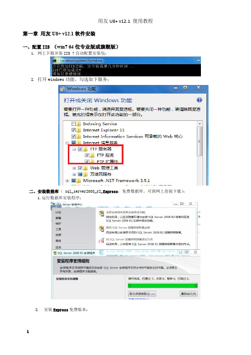
第一章用友U8+ v12.1软件安装一、配置IIS (win7 64位专业版或旗舰版)1. 网上下载并装IIS 7自动配置安装包;2. 打开windows功能,勾选如下服务;二、安装数据库( sql_server2008_r2_Express,免费数据库,可到网上直接下载);1.运行数据库安装程序;2. 安装Express免费版本;3.安装“默认实例”;4. 服务器配置(对所有SQL Server 服务使用相同帐户(U));5. 数据库引擎配置;①验证模式为“混合模式”;②为SQL Server系统管理员(SA)帐户指定密码(yzlf747688);6. 安装SQL Server 2008 R2 。
7. 安装U8 12.1安装包里3rdProgram/SQLServer2005_BC_x64程序;三、打开windows 功能中 telnet组件;1. 打开telnet组件(Telnet服务器和Telnet客户端都勾选);2. 启动“服务”(在搜索框中输入“服务”搜索),启动Telnet;※双击Telnet项或者从右键菜单选择“属性”,将“禁用”改为“手动”;※启动与Telnet有依存关系的组件(右键属性查看组件);※“启动”Telnet;四、进行SQL Server 2008 R2网络配置;1. 对SQL Server配置管理器进行网络配置;※启用TCP/IP协议:右键菜单点"属性" ,在分页菜单中选"IP地址",把"IP1"和"IP2"中"TCP端口"为1433,"已启用"改为"是;五、安装u8v 12.1(关闭杀毒软件/安装缺省组件/安装完毕/重启电脑/测试连接)六、连接数据库;1. U8应用服务器配置工具-数据源配置-增加(数据源:default;数据服务器:local);2. 初始化数据库(也可以:用友U8V12.1-→系统服务―→系统管理―→系统―→初始化数据库);七、软件破解(略);1. 停止任务栏右下角U8应用服务管理器中的UFNET、U8TaskService、U8DispatchService服务,并退出U8应用服务管理;2. 把ServerNT.exe复制到C:\Windows\SysWOW64目录替换原序;3. 把U8TaskService.exe复制到C:\U8SOFT目录替换原程序;4. 把UFSoft.U8.Framework.Login.BO.dll复制到C:\U8SOFT\U8Framework\Bin\Framework替换原程序;5. 插上USB加密卡,启动U8应用服务管理器中的UFNET、U8TaskService、U8DispatchService服务;八、更改计算机名和日期格式1. 修改计算机名(U8固定资产模块不识别复杂计算机名);2. 日期格式修改成YYYY-MM-DD ;。
UBNT设置教程_M2-M5

UBNT设置教程_M2-M5本教程适合ROCKET M2/NanoStation M5/ NanoStation M2/AG5G/NB5G等UBNT 150Mbps产品的配置,本教程只介绍接⼊点模式及客户端模式,也就是 Access Point及 Station。
名词解释:Airmax:这是由美国ubnt公司⼀项⽤于提升⽆线传输速率的⽆线技术,此技术仅限ubnt M2系列产品才能与之兼容,它的存在使⽆线带宽能得到最⼤限度的提升,⽹络承载能⼒也⼤幅提升,它⽆法与其他品牌⽆线AP兼容,甚⾄和ubnt 11g的产品也⽆法兼容。
(可以简单的理解为动态的控制客户端连接的速率)Access Point:即ap模式,⽆线接⼊点,可以理解为⽆线交换机,特点:通过RJ45(⽹线)输⼊,向外发射⽆线信号。
Station:站模式,也叫做客户端模式,这个模式和Client是⼀样的意思,特点接收⽆线信号,以RJ45(⽹线)输出组成⼀个桥接的⽆线⽹络,我们需要⼀个发射端,⼀个接收端,即AP模式《=====》station客户端模式。
如果我们只是需要⽤设备完成接收的作⽤,那麽使⽤Station客户端模式即可。
如果我们只是需要⽹桥做⽆线AP向外发射⽆线信号做覆盖,那麽⽤Access Point模式即可为了实现真正意义上是透明⽹桥,以下配置教程我们讲述的是wds桥接,我们的⽹桥也是根据wds所配置。
下边我们进⾏配置⽹桥1. 将我们的⽹桥按照⽹桥标签所⽰的⽅式进⾏连接,这⾥⽤的⽹线是有要求的,请务必采⽤国标的超五类纯铜线,⽹线制作的⽅式依照568B制作。
2. 在确定连好⽹线后,请将poe电源上Date IN与电脑⽹卡相连接,但看到电脑右下⾓显⽰,则说明连接已经正常,如显⽰,则请您检查⽹桥《====》POE电源Date OUT这段⽹线是否正常。
3. 将电脑的⽹卡ip设置为固定(在⽹桥设置完成后,ip地址就改为⾃动获取)4. 在ie地址栏输⼊http://192.168.1.20/ ,回车后,会提⽰输⼊⽤户名和密码,请输⼊⽤户名 ubnt,密码ubnt (均为⼩写),如果输⼊⽤户和密码后页⾯显⽰空⽩,则请点击浏览器菜单:查看>编码>其他>utf-8,点选后,页⾯即可正常显⽰。
sun_ultra_20_安装指南

Sun Microsystems, 请到以下网址提交您对本文档的意见和建议:/hwdocs/feedbackSun Ultra™ 20 M2 工作站安装指南文件号码 819-7863-102006 年 8 月,修订版 A请回收版权所有 © 2006 Sun Microsystems, Inc., 4150 Network Circle, Santa Clara, California 95054, U.S.A 。
保留所有权利。
Sun Microsystems, Inc. 拥有与本文档所述产品包含的技术有关的知识产权。
需特别指出的是(但不局限于此),这些知识产权可能包含在 /patents 中列出的一项或多项美国专利,以及在美国和其他国家/地区申请的一项或多项其他专利或待批专利。
本产品的某些部分可能是从 Berkeley BSD 系统衍生出来的,并获得了加利福尼亚大学的许可。
UNIX 是 X/Open Company, Ltd. 在美国和其他国家/地区独家许可的注册商标。
Sun 、Sun Microsystems 、Sun 徽标、Java 、Solaris 和 NetBeans 、Sun Ultra 是 Sun Microsystems, Inc. 在美国和其他国家/地区的商标和注册商标。
AMD 、Opteron 、AMD 徽标和 AMD Opteron 徽标是 Advanced Micro Devices 的商标或注册商标。
PostScript 徽标是 Adobe Systems, Incorporated 的商标或注册商标。
任何 CPU 备件或 CPU 替换产品只能用于修理或一对一替换按照美国出口法律出口的产品中的 CPU 。
除非已获得美国政府的授权,否则严禁将 CPU 用作产品升级件。
本文档按“原样”提供,对于所有明示或默示的条件、陈述和担保,包括对适销性、适用性或非侵权性的默示保证,均不承担任何责任,除非此免责声明的适用范围在法律上无效。
M-Series操作手册说明书
M108 - Enable Override ControlsM108 re-enables the feedrate override and/or spindle speed override controls if they were disabled with M109. A parameter of “1” indicates the feedrate override; “2” indicates the spindle speed override.Example:M109/1/2 ; disables feedrate and spindle speed overridesM108/1 ; re-enables feedrate overrideM108/2 ; re-enables spindle speed overrideM109 - Disable Override ControlsM109 disables the feedrate override and/or spindle speed override controls. It may be used before tapping with G85 to assure that the machine runs at the programmed feedrate and spindle speed. It is not necessary to specify M109 with G74 or G84; those cycles automatically disable and re-enable the override controls. M109 cannot be used in MDI mode.Example:M3 S500 ; start spindle in clockwise direction, at 500 rpmF27.78 ; set feedrate for 18 pitch tapM109/1/2 ; disable feedrate and spindle speed overridesG85 X0 Y0 R.1 Z-.5 ; tap a holeM108/1/2 ; re-enable overridesM115/M116/M125/M126* – Protected Move Probing Functions The protected move probing functions provide the capability to program customized probing routines.The structure for these commands is: Mnnn /Axis pos P p F f L1Where:nnn is either 115, 116, 125, or 126.Axis is a valid axis label, i.e., X, Y, Z, etc.pos is an optional positionP is a PLC bit number, which can be negative.F* is a feedrate (in units per minute.)L1* options for the M115/M116 commands that prevents an error if the probe does not detect a surfaceQ1 is an option for M115/M116 that forces the DSP probe to move a “Recovery Distance” on retries. (See Machine Parameter 13 for “Recovery Distance”)Note: the Q1 option only applies for DSP ProbesFor M115 and M116 functions, the indicated axis will move to pos (if specified) until the corresponding PLC bit p state is 1, unless p is negative, in which case movement is until the PLC bit state is 0(closed). A “p value” of 1 to80 (or -1 to -80) specifies PLC bits INP1-INP80. Warnings are generated in the CNC software message window for"Missing P value" and "Invalid P value." If “pos” is not specified, M115 will move the axis in the negative direction, and M116 will move the axis in the positive direction. Note if “pos” is specified, then if does not matter whether M115 or M116 is used. Regardless of whether or not pos is specified, movement is bound by the settings in the software travel limits as well the maximum probing distance (Machine Parameter 16).For M125 and M126 protected move functions, the behavior is identical to that of the M115 and M116 commands, except in regards to the PLC bit state. The M115 and M116 commands are to be used when one expects contact to be made and M125 and M126 commands are to be used when one does not expect any contact to be made.Example:Finding the center of a vertical slot. In this example, it is assumed that there is a probe connected to INP15 andthat the probe tip is positioned somewhere in the slot, such that movement along the X-axis will cause a probetrigger.M115/X P-15 F20 ; Move X minus at 20 ipm until probe tripM116/X P15 F5 ; Move X plus at 5 ipm until probe clears#100 = #5041 ; Record the point in user variable #100M116/X P-15 F20 ; Move X plus at 20 ipm until probe tripM115/X P15 F5 ; Move X minus at 5 ipm until probe clearsX[[#100+#5041]/2] ; Move X to center of slot*Usage is slightly different when using a DSP type probe. Please see below for dissimilarities between a standard DP4 probe and the DSP type probe.*M115/M116/M125/M126 - DSP Probe specific informationBefore attempting to use the protected move probing functions with a DSP type probe, please be sure to familiarize yourself with the DSP probe configuration in Chapter 9 of this manual. Using the protected probing moves with a DSP type probe may yield unexpected results if you do not fully understand the concepts and guidelines discussed in the DSP probe configuration section.If the control is configured to use a DSP type probe, all M115/M116 moves will perform window checking andrepeat on a failed window. On a failed window, a repeat attempt is made by returning to the starting point of the move.Protected move probing functions follow the same command format as that of a standard probe (Mnnn /Axis pos P pF f L1) with the following exceptions:f This will be ignored if “Force DSP Feedrate in M115/M116” has been set to yes.L1 Still prevents a fault from occurring. Stores last DSP position on failed window.L2 Like L1, prevents a fault from occurring but instead stores last mechanical pos. on failed window.Q1 On a failed window, force a pull back distance equal to the Probing Recovery Distance(Parameter 13), instead of moving back to the starting point.DSP position vs. mechanical position:Protected probing moves that are performed using a standard DP4 probe can collect only the point at which motion has stopped after detecting contact. This position is referred to as the “mechanical position”. When using the DSP type probe, it detects and stores the contact position “on the fly”. This position is in machine position (not a local WCS position) and is referred to as the DSP position.Example from above – Modified to use a DSP type probe:Finding the center of a vertical slot.M115/X P-15 ; Move X minus at DSP rate until probe trip (no feedrate needed)#100 =[[#24301]-[#2500]] ; Convert point to current WCS position, Store point in variable #100M116/X P15 ; Move X minus at 5 ipm until probe clearsM116/X P-15 ; Move X plus at DSP rate until probe tripX[[#100+[[#24301]-[#2500]]]/2] ; Move X to center of slotRetrieving the DSP position:The last stored DSP position for axes 1-5 can be retrieved from system variables #24301-#24305 unless theL2 switch was used in which case #24301-#24305 will contain the mechanical position after a failed window.M120 - Open data file (overwrite existing file)This M function will open the requested data file for writing. If no drive or directory is specified with the file name, then the file will be opened in the same directory as the CNC program. If the file cannot be successfully opened, then an error will be returned, ultimately terminating the job. If a data file is already open when M120 is called, that file will first be closed, then the new file opened.Example:M120 "probetst.dat" ; Opens probetst.dat file to write data tooNote: M120 and M121 also allow use of the string user variables #300 - #399 to specify a filename. As anexample, given that #300 = “myfile” and #301 = “cnc”M120 “#300.#301” ;Opens the file “c” for data recording.Keep in mind however that there is a quirk in the way that the M120/M121 operates that requires the '.' to be present so assigning #301 = “.cnc” and executing M120 “#300#301” does not work and generates a “Could not open file” error message.M121 - Open data file (append to existing file)This M function will open the requested file for writing at the end of the file. If no drive or directory is specified with the file name, then the file will be opened in the same directory as the CNC program. If the file does not already exist, it will be created. This is not an error. If the file cannot be successfully opened, then an error will be returned, ultimately terminating the job. If a data file is already open when M121 is called, that file will first be closed, then the new file opened.Example:M121 "c:\probetst.dat" ; Opens probetst.dat file to add data to itString variables #300-#399 may also be used to specify a file name. Please see M120 above for details.M122 - Record local position(s) and optional comment in data file This M function will write the current expected position value to the data file, in the usual format (i.e. axis label before number, 4 decimal places in inch mode, 3 decimal places in millimeter mode. Any comment that appeared on the line with M122 will be outputted after the position(s). With no axis arguments, M122 will write thepositions of all installed axes. With axis arguments, it will write the positions only of the requested axes. Positions will be written in local (not machine) coordinates, in native machine units. If no data file has been opened with M120 or M121 before M122 is called, then M122 will return an error and terminate the job. The parameter L1 may be used to suppress the new line character normally outputted after the last position. Furthermore, the output of axis labels, comma separators, and spaces can be enabled or suppressed via machine parameter 72 (see Parameter 72 in Chapter 14). If the control has been configured to use a DSP probe type, using parameter Q1 will write the values stored in #24301-#24305 to the file.Examples (M function and sample output):M122 ;comment -> X1.2345 Y-3.2109 Z-0.5678 ;commentM122 /X L1 -> X-1.5000M122 /X -> X-1.5000 X-2.0000M123 - Record value and/or comment in data fileThis M function will write the specified parameter value (if any) to the data file, followed by any comment that appeared on the line with M123. If a P value is specified, M123 will record the numeric value (4 decimal places in inches, 3 in millimeters). If neither a P value nor a comment was specified, M123 does nothing. This is not an error. If no data file has been opened with M120 or M121 before M123 is called, then M123 will return an error and terminate the job. The parameter L1 may be used to suppress the new line character normally outputted after the last value. The R and Q parameters can be used to specify the field width and precision, respectively.Furthermore, the output of axis labels, comma separators, and spaces can be enabled or suppressed via machine parameter 72 (see Parameter 72 in Chapter 14).Examples (M function and sample output):M123 ;1.2345 ->1.2345M123 P#A ; first macro argument ->1.2345 first macro argumentM123 Q0 P1.23 ->1M124 - Record machine position(s) and optional comment in data file Identical to M122 above except that the m124 reports machine position instead of a local WCS position.M127 - Record Date and Time in a data fileThis M function is used to write the date, time, and year to the specified data file called out by the M120 or M121.Examples (M function and sample output):M121 “testdata.dat”M127If you opened testdata.dat you would see: Day of week, Month, day, time, and year.(i.e. Wed Aug 29 11:56:57 2007)M128 – Move Axis by Encoder CountsM128 moves the requested axis by L which specifies an encoder count position or quantity. The L parameter is subject to the current G90/G91 mode (absolute/incremental).Example:G91 M128/X L-5000 ; move the X axis incrementally by -5000 countsM129 - Record Current Job file path to data fileThis M function is used to write the current job’s file path to the specified data file called out by the M120 or M121.Example:Run a job named c which contains the following 2 lines:M121 “output.txt”M129If you opened the output.txt file you would see:c:\cncm\ncfiles\c。
解决引导内核遇到undefinedinstruction的错误
解决引导内核遇到undefinedinstruction的错误其实在上⼀篇随笔之前,就是在启动linux 内核的时候,出了点问题刚Starting kernel ...就出现了undefined instrction,这是什么问题呢?在⽹上也搜了不少资料,有两篇很有启发就是这两篇。
我们先来了解下mkimage这个命令,重要关注loadaddress和entry address./mkimage -A arch -O os -T type -C comp -a addr -e ep -n name -d data_file[:data_file...] image-A ==> set architecture to 'arch'-O ==> set operating system to 'os'-T ==> set image type to 'type'-C ==> set compression type 'comp'-a ==> set load address to 'addr' (hex)-e ==> set entry point to 'ep' (hex)-n ==> set image name to 'name'-d ==> use image data from 'datafile'-x ==> set XIP (execute in place)mkimage是将zImage之前加上64字节的镜像头所以如果使⽤mkimage⽣成内核镜像⽂件的话,会在内核的前头加上了64byte的信息,供建⽴tag之⽤。
bootm命令会⾸先判断bootm xxxx 这个指定的地址xxxx是否与-a指定的加载地址是否相同。
M7 1 用户手册说明书
USER MANUALM7Table of Contents1.GENERAL INFORMATION (2)1.1W ARNINGS AND RECOMMENDATIONS (2)1.2F UNCTION AND F EATURE (2)1.3F RONT VIEW (2)1.4R EAR VIEW (2)1.5D IMENSIONAL DATA AND INSTALLATION HEIGHTS (3)1.6W ALL-MOUNTED INSTALLATION (4)2.SYSTEM APPLICATION (5)2.1V ILLA OR SINGLE-FAMILY CONTEXT (5)2.2A PARTMENT BLOCK OR MULTI-FAMILY CONTEXT (5)3.OPERATION DESCRIPTION (7)3.1M AIN P AGE (7)3.2S HORTCUT PAGE (7)3.3A DJUSTING PAGE (8)3.4BASIC OPERATIONS (8)3.5SETUP INSTRUCTIONS (11)3.6U PLOAD PICTURE AS WALLPAPER (20)3.7U PLOAD MUSIC AS RINGTONE (20)4.SPECIFICATIONS (20)1. General information1.1 Warnings and recommendationsIt is important to read this manual carefully before proceeding with the installation. The guarantee automatically expires for negligence, misuse, tampering by unauthorizedpersonnel.The Video internal unit must only be installed indoors; it must not be exposed to water drops orsplashes.1.2 Function and Feature⚫ 7” capacitive touch screen monitor ⚫ Based on Android system ⚫ IP over 2-wire non-polarity ⚫ 1024(RGB)x600 pix resolution ⚫ Picture in Picture function⚫ Indicator: Power, mute, message, WIFI ⚫ Picture and video save⚫ Support the secondary door bell and ringer extension ⚫ Support WIFI for cloud intercom⚫Flexible power way: support remote and local power1.3 Front view+-1234567891. 7” touch screen display (16: 9)2. SD card slot3. 24v DC input4. Reset button5. Indicate lights for power, mute, message, WIFI6. Increase the volume7. Volume indicate lights8. Reduce the volume1.4 Rear view123456781. Mic2. Loudspeaker3. Interface for 2nd door bell and extension ring4. Interface for additional power supply, non-polarity5. Interface for 2-wire IP interface, non-polarity6. Configurator J1: remove for additional power supply7. Configurator J2: Master/Slave, remove for Slave8. SD card slot1.5 Dimensional data and installation heightshttps:///1201207-power_icon.html+-HOME232mm133m m15mmGround160 ~ 165m m135 ~ 140m mRecommended height, unless otherwise required by the law1.6 Wall-mounted installation12345671 - Mark the location of the bracket holes2 - Drill3 – Install expandable screw4 - Fix the wall bracket5 - Connect the wires with the interface according to the wiring diagrams.6 – Insert the connector into the monitor, using index finger, middle finger, ring finger and littlefinger is easy to insert7 - Put the monitor on its wall bracket2.System Application2.1Villa or single-family contextMonitor 3 PowerDoor StationSmartPhone APP INTERNETMonitor 2Monitor 1In villa(single-family) systems all of the unit can be connected with the power.2.2Apartment block or multi-family contextHome 1DistributorDoor StationSmartPhoneAPPINTERNETHome 2Home 3PowerIn multi-family systems (apartment blocks), you need the distributor to connect all of the monitor and door station.The distributor can be connected with each other via CAT-5 cable.Distributor1PowerPowerDistributor NPowerDistributor 2CAT-53.Operation Description3.1Main PageThe Main Page is your starting point for using all the applications on your monitor.Touch anywhere of the screen on monitor in standby mode, the Main Page will appear as follows:Icon description:System status icons: from left to right-Connection-Mute-Wi-FiDoor Connection to the outdoor panel to show imageCamera Connection to the IP cameraRecord Pictures and video reviewIntercom Call to other monitors in the house (if any).Setting Enter setting menuScreen off Shut the screen. The screen will automatically switch off after 30” if no activity is done.. Sliding the main page to the left will show shortcut page.. Sliding the main page to the right will show adjusting brightness and volume page 3.2Shortcut pageIcon description:WIFI Deactivate / activate WIFI (master monitor only)Silence Activate / deactivate do not disturb modeLeaving Deactivate / activate leaving mode,when leaving mode is active, the silence and transfer function will be onTransfer Deactivate / activate call transfer functionwhen transfer function is activate, the call from door panel will be transfer to APP.3.3Adjusting pageIcon description:Speaker Volume Adjust the volume from door stationRing Volume Adjust the ring/video volumeBrightness Adjust the screen brightness3.4BASIC OPERATIONSEnter Door ListP ush “Door” button Push door panel you want to see Then the monitor page will be shown as follows:1 23 4 5 6 7 8Icon description:1.The additional IP camera window2.Button for adjusting video quality3.Take picture4.Take video5.Open the first door6.Open the second door7.Start to talk with visitor8.Return home pageNote: The name of door panels can be set by user, Door1, Door2, Door3 and Door4 in default.The instruction to set name can be found from ‘Setting-Door’ in the Setting.Enter Camera ListP ush “Camera” button Push camera you want to seeThen the monitor page will be shown as follows:12 3Icon description:1.Button for adjusting video quality2.Take picture3.Return home pageNote: The name of camera can be set by user, Camera1, Camera2, Camera3 and Camera4 in default.The instruction to set name can be found from ‘Setting-Camera’ in the Setting.Enter Intercom ListP ush “Intercom” button Push the monitor you want to dial Then the dialing page will be shown as follows:12Icon description:1.Adjust volume2.Cancel the callThe called page is as follows:123Icon description:1.Adjusting volume2.Answer the call3.Hung up3.5SETUP INSTRUCTIONSAll settings should enter the setting page by touching the icon ’Setting’ from main page:Setting-Door Panel1From door list page above, choose the door you want to set, it will show the following page:123456Icon description:1.Set door panel name2.Set auto record mode. (None, Photo, Video)3.Set door panel ring tone4.Set door lock open time. (1s,2s,3s,4s,5s,6s,7s,8s,9s)5.Select IP camera for picture in picture function. To activate this function, please add IPcamera first. See “Setting-Camera”6.Turn on/off fish eye lensCloud intercomPress cloud menu, the following page will be shown:1Use App to scan the QR code, and add it to device list.The App link for smartphone:Android APP IOS APPNote: Users should turn on [Leaving] mode or [Transfer] mode to enable cloud intercom function Setting-Memory12345Parameter description:1.The usage of the memorya)Red means the volume of images storedb)Green means the volume of videos storedc)Grey means the available volume2.The number of pictures record3.The number of videos record4.The video time when take video5.Format MemorySetting-WIFI12Parameter description:1.WIFI switcher2.Select a WIFI network to joinSetting-Motion Detection1234Setting description:1.Turn on/off motion detection2.Set the lock to open when motion happen3.Set the time schedule for motion detection function4.Take picture when motion happenSetting-Mute123Setting description:1.Deactivate / activate “manual” for mute functionW hen activate “Manual” for mute function, there will no ring when visitor call from door panel.2.Deactivate / activate “schedule” for mute function3.Set schedule mute periodW hen setting “Schedule” mute function, there will no ring in the setting time. Setting-Time&Date12345Setting description:1.Turn on/off synchronization time automatedly2.Set time zone3.Set Date4.Set Time5.Deactivate / activate 12-hour or 24-hour formatSetting-Language1Setting description:1.Set languageSetting-Wallpaper12Setting description:1.Push to choose a new picture as wall paper2.The existing wallpaperSetting-SetupTo set monitor address, add RFID card, add IP camera, and upgrade system, user needs input password in the following page:1Note: default password: 12345Setting-Room-Address1234Parameter description:1.Set room number, the value can be 01 ~ 322.Set room name3.Set extension room number, the value can be 1-44.Confirm and restart the deviceSetting-RFID Card1234Setting description:1.Add new RFID card2.Delete all RFID card3.The number of existing RFID card4.The lock to open when swiping RFID cardSetting- Add RFID Card1For example: If apartment 01 wants to add RFID card, the procedure:1.P ush “Setting” →“RFID card” →“Add card”,2.Swipe the card on door station one by one, then push the 01 call button to finish it3.Sound prompt: add card - Beep 1 time, add card success: Beep 2 timesNote: When swipe card on the door station, the limited time is 90SThe indoor monitor can talk with door station when adding RFID card.Setting- swipe short time to open lock1, long time to open lock21Description:Time for short time swipe:1sTime for long time swipe: 3sSetting-Camera123Icon description:1.Modify IP camera setting2.Delete IP camera3.Add new IP cameraWhen push icon1 and icon 3, the following page will be shown:12345Parameter description:1.Type: Choose the brand of IP camera2.IP address name: set the name for IP camera.3.IPC address: Set IP address of IP cameraNote: the suggestion IP address for IP camera: from 192.168.137.134 to192.168.137.254ername: Fill in username of IP camera5.Password: Fill in password of IP cameraSetting-System12345678Setting description:1.Show hardware version2.Show software version3.Show model name4.Show Room number5.Show IP address6.Push to upgrade system7.Push to restore setting8.Push to change [setting] passwordAfter pushing upgrade button, the following page will be shown:1Setting description:1.Upgrade via SD carda.Create a new folder named “u pgrade”Note: please use lowercase lettersb.Put the system software in itc.P ush “Setting” →“System” →”System upgrade” →”SD upgrade” to start3.6Upload picture as wallpaperYou can use your own picture as the system wallpaper, the operation procedure:1.Prepare a Micro-SD card2.C reate a new folder named “w allpaper”, and copy your picture in itNote: please use lowercase letters3.P ush “Setting” →“Wallpaper” →”Choose a new wallpaper” to set3.7Upload music as ringtoneYou can use your own music as the ring tone, the operation procedure:1.Prepare a Micro-SD card2.Create a new folder named “ringtones”, and copy your music in itNote: please use lowercase letters3.P ush “Setting” →“Door” →”Ringtone” to set4.SpecificationsCategory SpecificationInput power DC: 24v, 50Hz/60HzPower Consumption Max: 6W, standby: 3WTFT LCD 7-inch digital TFT LCDLCD resolution 1024(RGB) x 600Connection with door station Support four 2-wire door stations (Maximum)Connection with CCTV Support 16 IP camera input (Maximum) Connection with extension monitor Support 3 extension monitorsMemory capacity TF card: 1024 pictures, 128 videos Dimensions (mm) 232mm*133mm*15mmWeight(kg) 0.43kg。
外研社版八年级英语上册M1U1教学设计课件
English is verybirmainpstoorrmtant and useful.
Where can we see English in our daily life?
How do you usually learn English?
li_s_te_n_ing
( C )2.Which is not a good way to learn English? ________.
A.We在sh课ou堂ld 上alw我ay们s s应pea该k E一ng直lis说h i英n c语lass. B.WLeetr’sy t让troys我tpoes们apke尽Eakn可gElni能sghli多asshm的asu说mchu英acsh语paoss吧psoibslsei.ble.
letter
spelling pronunciation
grammar
How to learn English well?
1 Read the instructions and check(√)the ones you understand.
√ 1. Work in pairs. Ask and answer the questions. √ 2. Correct the spelling. √ 3. Listen and check the words you hear. √ 4. Practise saying the words. √ 5. Match the words with their meanings. √ 6. Complete the sentences with the words in the box.
Speaking:Let’s try to speak English as much as _p_o_s_s_ib_l_e_. _/W__e__sh_o_u__ld__a_lw__a_y_s_s_p_e_a_k_E__n_g_li_s_h_i_n class.
- 1、下载文档前请自行甄别文档内容的完整性,平台不提供额外的编辑、内容补充、找答案等附加服务。
- 2、"仅部分预览"的文档,不可在线预览部分如存在完整性等问题,可反馈申请退款(可完整预览的文档不适用该条件!)。
- 3、如文档侵犯您的权益,请联系客服反馈,我们会尽快为您处理(人工客服工作时间:9:00-18:30)。
高中英语整整体教学与细节优化学案—M8 U1 Welcome to the unit & reading (T)
第 1 页 共 8 页 M8 U1 Welcome to the unit & reading (T) 一、 单词拼写 1. Having suffered from the war for too long, Libyans(利比亚人民)are desperate for peace. 2. His efforts to raise money for his program were in vain, because no one showed any intention/intended to take a cent out of their pocket. 3. Crying is usually considered characteristic(特征)of the female. 4. She was always very generous(慷慨的)in her charity. 5. The police had to make a forcible(强迫的/强制的) entry into the house where the criminal was hiding. 6. Oliver Twist was written by one of the greatest novelists in the world. 7. The antique(古董)vase was made in 高中英语整整体教学与细节优化学案—M8 U1 Welcome to the unit & reading (T)
第 2 页 共 8 页 1628, so it is worth a lot now.
8. Violent criminal/crime like that are/is a danger to society. 9. His political reputation was ruined by his abuse of the power. 10. My hobby is a good tool to relieve the tension that builds up at work. 二、 选词填空 have a place in, would rather, come out, be set in, have nothing to do with, in vain, be bent on, live up to, base…on, be adapted from 1. They were very happy that their efforts had not been in vain. 2. If you want to have a place in the IT world, you will have to double your efforts. 3. The country girl was bent on going to that university as she liked urban life very much. 高中英语整整体教学与细节优化学案—M8 U1 Welcome to the unit & reading (T)
第 3 页 共 8 页 4. Many people don’t like classics because
they consider they are old and boring and have nothing to do with life today. 5. Great Expectations is set in England in the early 1800s. 6. This new film is said to be adapted from a novel by Jane Austen. 7. A good marriage is based on trust. 8. Do you know that the first textbooks written for teaching English as a foreign language came out in the 16th century? 9. He is taking pains(尽力) to reach the goal set by his parents because he wants to live up to their expectations. 10. —Would you like him to paint your door with yellow stars? —I’d rather he painted it blue, and without any decoration. 三、 单项选择 1. The young man is _____ becoming a 高中英语整整体教学与细节优化学案—M8 U1 Welcome to the unit & reading (T)
第 4 页 共 8 页 lawyer and winning the girl’s love.
A. bent with B. bending on C. bent on D. bending to 2. Li Ping, you can borrow books from the school library, but _____. A. one at a time B. one by one C. one once D. one after another 3. —Do you mind if I keep pets in this building? —_____. A. I’d rather you didn’t, actually B. Of course not, it’s not allowed here. C. Great! I love pets D. No, you can’t 4. I dislike _____ you treat me in this way. A. when B. it if C. it when D. one that 5. —I was riding along the street and all of a sudden, a car cut in(超车/插入) and knocked me down. 高中英语整整体教学与细节优化学案—M8 U1 Welcome to the unit & reading (T)
第 5 页 共 8 页 —You can never be _____ careful.
(你越仔细越好/无论你怎么样仔细也不过分。) A. much B. very C. so D. too 6. His new story ________ what happened in the coal mine many years ago is the best seller this year. A. based on B. basing on C. was based on D. was basing on 7. —I’m not good at dancing, you know. —______ Just for fun. (09浙江金华十校联考) A. Don’t say so. B. Come on! (快/来吧!) C. What a pity! D. Come out! 8. Hiking by oneself can be fun and good for health. It may also be good for ________ building. 高中英语整整体教学与细节优化学案—M8 U1 Welcome to the unit & reading (T)
第 6 页 共 8 页 A. respect B. friendship
C. reputation D. character 9. It was too hard for the firefighters to get close to the burning building. All their attempts to rescue the people trapped were______. A. in vain B. in return C. in place D. in danger 10. Since her childhood, she has tried her best to ______ her ideals. A. live with B. live up to C. live through D. live on 11. —Will you join us in the game? —Thank you, _______(07江西21) A. but why not? B. but I’d rather not. C. and I won’t D. and I’ll join. 12. —Why on earth(到底/究竟) didn’t you come? —I _______ call on you, but was discouraged from doing so due to the