microsoft translator 使用手册
Wordfast软件使用说明

Wordfast软件使用说明Wordfast使用说明首先,打开Wordfast,菜单栏显示六项内容,分别是:File(文件)、Edit(编辑)、Translation Memory(翻译记忆库)、Terminology(术语)、Window(窗口)、Help(帮助)。
当我们要进行翻译的时候,首先要创建或者打开一个Project,因为Project中规定了我们所要进行翻译的源语言和翻译过后产生的目标语言,如下图所示:在这里我们选择Create Project,单击选项,会弹出如下对话框:其中,Project name 无要求,但必须要填写,下面的Source locale 和 Target locale 就是我们翻译时的源语言和目标语言,一定要进行正确的设置,否则翻译出来的内容就不是我们预期的内容。
进行完设置以后,点OK确定,我们可以看到,刚刚新建的Project已经存在于我们的List中了。
选中我们刚刚新建的Project,点OK,下面,我们所进行的翻译就全在这个Project 中进行了。
用户点击确定后,会出现下面的界面:这个是参数选择界面,在这里我们可以选择需要关联的语料库和术语库,即Translation Memory和Terminology。
首先我们看Translation Memory,在TM下面有两个选择项,一个是Local,还有一个Remote其中Local是本地语料库,也就是我们本机电脑上存放的语料库资源,对于那些已经建好库的,我们可以直接在Local TM List中选择我们需要用到的语料库,也可以使用Add TM 添加List中没有的其他语料库,这个我们不多做解释,我们只需要找对语料库存放的路径并注意语料库中的源语言和目标语言与我们当时创建Project时所选择的一致即可,下面我们模拟没有语料库的使用。
单击Create TM在出现的对话框中选择语料库的存放路径和名字,并且选择和Project一致的源语言和目标语言,点OK这样我们新建的语料库就出现在List中了,选中这个语料库,在这里有两个复选框,一个Selected,一个Read only,选择Selected的时候我们能够对语料库进行修改和入库操作,(当勾选Read only时我们只能够使用语料库中的内容而不能对内容进行修改。
EC-Lab software 中文操作手册

目
录
1. 介绍 ............................................................................................................................................. 6 2. EC-Lab 软件:设置.................................................................................................................... 7 2.1 开始程序............................................................................................................................ 7 2.2 EC-Lab 软件准备和运行实验 ........................................................................................... 9 2.2.1 EC-Lab 主界面 ...................................................................................................... 9 2.2.1.1 设置工具栏 .................................................................................................. 9
TagEditor使用指南
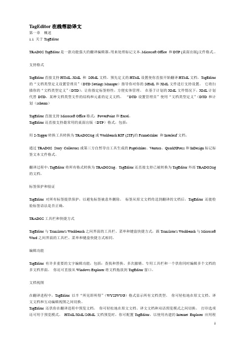
TagEditor在线帮助译文第一章概述1.1 关于TagEditorTRADOS TagEditor是一款功能强大的翻译编辑器,用来处理标记文本、Microsoft Office 和DTP (桌面出版)文件格式.。
支持格式TagEditor直接支持HTML、XML 和SGML文档。
预先定义的HTML设置使你直接开始翻译HTML文档。
TagEditor 的“文档类型定义设置管理员”(DTD Settings Manager)指导你对你的SGML和XML文件进行支持设置。
它将扫描你的“文档类型定义”(DTD),让你指定标签特性,方便实体管理。
在基于计划的XML文件情况下,XML计划代替DTD,某种文档类型文件的结构和元素的定义文档。
“DTD设置管理员”使用“文档类型定义”(DTD和计划(schema)TagEditor直接支持Microsoft Office格式:PowerPoint和Excel。
TagEditor还直接支持最常用的桌面出版(DTP)格式,包括:用S-Tagger转换工具转换为TRADOStag或Workbench RTF (STF)的FrameMaker 和Interleaf文档。
通过TRADOS Story Collectors或第三方自然导出工具生成的PageMaker、Ventura、QuarkXPress和InDesign标记标签文本文件格式。
翻译过程中,TagEditor将所有格式转换为TRADOStag。
TagEditor还直接支持已被转换为TagEditor外部TRADOStag 的文档。
标签保护和验证TagEditor对所有标签提供保护,以避免标签被意外删除。
标签从原文文档传送到翻译的文档后,TagEditor还能检验标签语法是否正确。
TRADOS工具栏和快捷方式TagEditor与Translator's Workbench之间界面的工具栏、菜单和键盘快捷方式,跟Translator's Workbench与Microsoft Word之间界面的工具栏、菜单和键盘快捷方式相同。
灵格斯翻译家使用手册

灵格斯翻译家使用手册安装灵格斯1、从灵格斯翻译家网站下载软件的安装程序到本机硬盘.2、双击安装程序, 进行安装.3、安装过程中, 如果没有特别的需求, 可以一路按“下一步” 直至安装完成.注意:∙请从官方网站或官方指定的下载网站获取灵格斯的安装程序, 切勿下载来源不明或所谓的绿色版, 以免造成不必要的损失和使用上的种种故障.∙安装前, 请确认已经关闭了其他程序, 特别是防病毒软件和防火墙软件, 以便正常顺利安装.设置主程序灵格斯翻译家的主程序已经安装到操作系统中了, 为了更好地使用灵格斯翻译家带来的便利, 我们需要在使用前对主程序进行设置.首先, 启动灵格斯翻译家, 点击程序界面左侧选项中的“设置”, 激活设置面板.屏幕取词点击“翻译” 选项标签, 对鼠标屏幕取词进行设置.∙鼠标取词: 用鼠标将光标移到词上面时, 再加上组合键就可翻译该词.∙鼠标左键取词: 用鼠标将光标移到词上面时, 按下〔鼠标左键+组合键〕就可翻译该词.∙鼠标右键取词: 用鼠标将光标移到词上面时, 按下〔鼠标右键+组合键〕就可翻译该词.∙鼠标中键取词: 用鼠标将光标移到词上面时, 按下〔鼠标中键+组合键〕就可翻译该词.∙延迟: 做以上动作时延迟几毫秒才做翻译动作.∙支持本地语言映射: 选中后, 在简体中文用户界面下, 会自动转换词典中的繁体中文内容为简体;在繁体中文用户界面下, 则会自动转换词典中的简体中文内容为繁体. (注: 本功能需要配合支持映射功能的词典使用)常规接着, 点击“常规” 标签, 对软件的常规项目进行设置.∙选择用于Web 搜索的搜索引擎: 当我们在右上角搜索框内输入文字, 并按下Enter 键时, 会连到互联网搜索引擎.∙保存的查询历史个数: 查询的词语的历史纪录.∙登录至Windows 时, 运行Lingoes: 打勾此项, 则会在开机时启动此程式.∙启动后最小化: 开启此程式的, 会缩到工具列上.热键∙打开主窗口: 即打开Lingoes 的视窗.∙鼠标取词开关: 按此热键会“关闭/打开” 使用滑鼠取词.∙朗读: 会朗诵所选取的文字.∙剪贴簿取词开关: 按此热键会“关闭/打开” 使用剪贴簿取词. ∙复制解释: 会把该查询的解释结果复制至剪贴簿.语音∙音量: 调整发音时的音量大小.∙音调: 调整发音时的音调.∙速度: 调整发音时的速度.∙即时发音: 取词时随便朗诵该词语.如果要下载更多的语言发音, 或是听不到语言发音的话, 可以点击一下“下载TTS 语言引擎和语言包...”, 然后会连结官方网站的网页. 下载后, 双击即可完成安装.安装及设置词典操作如下:1. 首先, 按一下, 接着会出现如下图:2. Lingoes 把词典分成三个方向, 每个方向都可以独立运作:∙词典安装列表: 即输入词语会查询的词典.∙索引组: 即输入词语, 会不会出现相近词语.屏幕取词组: 即取词翻译.3. 如果要下载更多词典, 只要按一下“从Lingoes 下载词典即可”, 然后会连到作者的网站, 选择你要下载的词典, 下载完毕后按两下安装即可.查阅单词的翻译及更多资料1. 首先, 找到2. 在里面输入词语后, 按Enter 键即可, 如下图:3. 而若要查询单一词典的结果, 只要在左侧选择相关词典即可.4. 而如果要找该词语的更多搜寻结果, 请在右上角输入内容, 并按Enter键便可以在新的浏览器窗口中打开搜索引擎的搜索结果.Tips: 您可以按放大镜旁向下的小箭头, 以使用不同的搜寻引擎.全文翻译当你有一段文章看不懂时, 或有一段文章想要翻译时, 即可输入该段文章, 来进行全文翻译.操作如下:1. 按一下「文本翻译」, 如下图:2. 白色空白处为输入文本框, 输入完后选择翻译引擎, 设置一下源语言和目标语言, 按一下“翻译”, 稍后即可得到翻译结果.3. 翻译的结果不一定都是准确无误的, 建议多比较几字翻译引擎翻出来的结果, 及多充实单词和语法的知识, 才是解决问题的根本.注: 全文翻译功能需要联机到互联网.发音查询的词汇Lingoes 利用操作系统附带的TTS语音引擎, 让您听到英文单词、短语、句子的发音. 您也可以通过安装其他语种的语音引擎得到对应语种的文本朗读效果.操作如下:1. 输入完查询的词语, 按Enter 会出现结果.2. 选择所要发音的文本部分, 并按一下, 或者按一下你所设定的发音热键.3. 接着, 就可以听到Lingoes 朗读选中的文本了.复制, 列印与储存查询结果我们可以利用Lingoes 轻松地把查询结果复制, 打印, 与保存起来.操作如下:1. 首先, 反白你所要处理的部份.2. 找到以下图示:o: 复制选择的内容.o: 保存查询的内容.o: 打印查询的内容.3. 以打印而言, 我们可以按钮, 以将查询的内容列印出来.下载真人发音及TTS 合成发音的语音库使用真人发音安装真人发音语音库安装真人语音库的方法非常简单,只要打开”灵格斯安装目录“下的speech文件夹, 在里面创建一个子文件夹(文件夹命名是随意的,建议使用语音库的名称),然后将下载到的语音库压缩文件解压到这个目录下即可。
多功能一体机 说明书

1 前言 ......................................................................................................................1-1 希望您成为本公司产品的满意用户 .......................................................................... 1-1 安全须知.................................................................................................................. 1-2 警告和注意符号的含义 ............................................................................................ 1-2 图标的含义 .............................................................................................................. 1-2 警告......................................................................................................................... 1-3 注意......................................................................................................................... 1-4 日常使用注意事项 ................................................................................................... 1-5 激光安全.................................................................................................................. 1-6 内部激光辐射 .......................................................................................................... 1-6 激光安全标签 .......................................................................................................... 1-9 臭氧释放.................................................................................................................. 1-9 关于镍氢电池的注意事项 ...................................................................................... 1-10 关于操作手册 ........................................................................................................ 1-11 手册中惯例的解释 ................................................................................................. 1-11 [ ] 键...................................................................................................................... 1-11 基本概念及符号的说明 .......................................................................................... 1-12 送纸....................................................................................................................... 1-12 “寛度”和”长度” ....................................................................................................... 1-13 纸张方向................................................................................................................ 1-13
凌拓MAX1464EVKIT评估板使用手册说明书

General DescriptionThe MAX1464 evaluation kit (EV kit) is designed to evaluate the MAX1464 high-performance, low-power, low-noise multichannel sensor signal processor. The EV kit includes: an evaluation PCB, the EV board that contains a MAX1464 signal conditioner with a typical application circuit, and potentiometers that act as sensor inputs to the MAX1464; an interface PCB, KEY, which acts as a voltage level translator between the EV kit and the com-puter; a parallel-port extension cable; plus, supporting software, program examples,and related documenta-tion and application notes.The DB25 pin connector allows a PC’s parallel port to provide the interface. Two Windows ®-based software (hardware debugger and control program) provide a friendly graphics user interface (GUI) to utilize the fea-tures of the MAX1464, as well as to perform sensor compensation of one device. The Hardware Debugger program includes multiple tabs for accessing relevant registers and ports, writing programs to the on-chip flash memory, downloading flash memory contents into a file,etc. Use the Hardware Debugger program to learn the MAX1464 functions and see the significance of individ-ual registers and ports. The Control program includes functional buttons to have the chip perform a series of predefined lower level operations, such as pushing sin-gle buttons to read the ADC. The Control program can be used to perform 2nd-order sensor compensation and calibration.The EV board can be powered by either a fixed +5V supply or by an +8V to +40V supply that is regulated to +5V by a regulator present on the EV kit board before it is applied to the MAX1464 chip. J umper J U1 must be set consistently with the used power supply.Order the MAX1464 EV kit for comprehensive evaluation of the MAX1464 using a PC with an available parallel port.Windows is a registered trademark of Microsoft Corp.Features♦Proven PCB Layout♦Windows 98/NT/2000/XP Compatible♦On-Board Potentiometers Act as Sensor Inputs ♦Spare Area for Simple-Circuit Breadboarding ♦LEDs for Visual Verification ♦+5V or +8V to +40V Possible Supply ♦Included Interconnect Cables ♦Included Additional SamplesEvaluates: MAX1464MAX1464 Evaluation Kit________________________________________________________________Maxim Integrated Products 119-0582; Rev 0; 12/06For pricing, delivery, and ordering information,please contact Maxim/Dallas Direct!at1-888-629-4642, or visit Maxim’s website at .Ordering InformationComponent SuppliersMAX1464 EV Kit FilesComponent ListEV Kit Component Listing these component suppliers.E v a l u a t e s : M A X 1464MAX1464 Evaluation Kit 2Component List (continued)Interface Board (KEY) Component ListQuick StartRequired Equipment •MAX1464 EV kit• A fixed +5VDC power supply•Computer running Windows 98/NT/2000/XP with an available parallel port (USB-to-parallel-port convert-ers not supported)•A multimeter•One parallel (printer) cableNote:In the following sections, software-related items are identified by bolding. Text in bold refers to items directly from the EV kit software. Text in bold and underlined refers to items from the Windows 98SE/2000/XP operating system.Procedures Applying Power to the MAX1464 EV Board 1)Verify that all jumpers on the EV kit board are setper the default setting shown in Table 1.2)Connect a fixed +5V power supply to the EV kitboard TB2 +5V terminal.3)The LEDs on the EV kit board start blinking. TheMAX1464 EV kit is shipped with a program, EVTEST1.hex, preloaded in the MAX1464 flash memory. This program alternatively flashes the two LEDs on the EV board.Setting Up for Digital Communication 1)Download the latest MAX1464 software from theMaxim website.2)Start the INSTALL.EXE program and follow theinstructions to install all MAX1464 applications pro-grams and to copy supporting files to your computer.3)Set up the MAX1464 EV kit by connecting the EVboard and the KEY using the 16-pin ribbon cable.Connect the KEY to the PC’s parallel port using a 25-pin straight-through, female-to-male cable.Example of Using the Hardware Debugger 1)Start the Hardware Debugger program from Start |MAX1464 EV kit | Hardware Debugger.2) A window (Figure 1) appears on the monitor.3)Read the text in the window next to the Check CPUstatus on the top row and verify that it reads Running or Halted. Any other reading indicates a hardware and/or setup problem. Fix the problem before continuing to the next step. The next few steps detail loading a new LED double blinking pro-gram to the MAX1464 flash memory and running it.4)Press the Flash Memory tab in the HardwareDebugger window.5)Press Load Buffer from file tab.6)Select … | MAX1464 | examples | cctmr1-64.hexfile to read the .hex file and save it in the temporarybuffer.7)Press Write to device tab to write the cctmr1-64.hexprogram to the flash memory.8)Press Verify device against buffer to verify that theflash memory write operation is successful.9)Execute the LED double-blinking program bypressing on the Run CPU button. The LEDs startblinking. This process verifies that the EV kit con-nections are correct, the EV board jumpers are setcorrectly, and the computer interface is working.Example of Using the Control Program Note:Exit the Hardware Debugger before starting theControl program.This section demonstrates how to start the Controlprogram and make the basic measurement of the inputvoltage.1)Start the Control program from Start | MAX1464EV kit | Control Program.2) A window (Figure 2) appears on the monitor.3)The DUT?button turns green if the hardware setupis correct and communication with the MAX1464 isestablished. A red button indicates a hardwareand/or setup problem. The next few steps detailreading the signal applied on the MAX1464 inputand write to the Data Array, which is the input tothe compensation algorithm.4)Set the value of This Temp Point and This PressPoint to match one of the test conditions displayedin the Data Array.5)Press the Read ADC button to convert the on-chiptemperature sensor output and channel 1 input volt-age and display the results of both conversions inthe Data Array.6)To read other input voltages, adjust VR1 and VR2potentiometers and repeat steps 5 and 6.7)Refer to the MAX1464 Control program manual fora full description of Control program capabilities.Evaluates: MAX1464 MAX1464 Evaluation Kit_______________________________________________________________________________________3E v a l u a t e s : M A X 1464Detailed Software DescriptionTwo independent programs have been provided for the MAX1464 to aid the user in evaluating and designing in the MAX1464 signal conditioner into a product.Hardware DebuggerThe hardware debugger program includes multiple tabs for accessing the relevant registers and ports,writing programs to the on-chip flash memory, down-loading flash memory contents into a file, etc. Use the hardware debugger program to learn the MAX1464functions, registers, and ports.CPU Registers r0..rf, p0..pfIn this window, users can read/write the CPU (module)registers, program counter r0, r1. Users can also read/write the CPU ports p0 through pf when the CPU is halted.ADC ModuleIn this window, users can access the ADC control, ADC configuration, and ADC data registers for all three chan-nels (channel 1, channel 2, and temperature sensor).DOP ModuleIn this window, users can access the DOP control, DOP configuration, and DOP data registers for both output channels and the op amp configuration register.Other ModulesIn this window, users can access registers related to the timer, power control, oscillator, and GPIOs.Flash MemoryThis window can be used for all flash-memory opera-tions, such as writing flash memory to/from a file.Program ListingIn this window, users can view the list file of an assem-bly program. Select the filename from the File pulldown menu.MAX1464 Evaluation Kit 4_______________________________________________________________________________________Figure 1. Hardware Debugger WindowControl Program (MAX1464 Main.exe) The Control program includes functional buttons to have the MAX1464 perform a series of predefined lower level operations, such as reading the ADC, loading a file into flash memory, etc. The Control program can be used to perform a 2nd-order temperature compensation.The main purpose of the Control program is to provide the user with a tool to easily compensate a sensor. The compensation algorithm defined in Application Note 3649, MAX1464 Signal-Conditioner, Sensor Compensation Algorithm, has been implemented. All the user needs to do is to properly set up the EV kit/sensor and the environment condition for the sensor, and press the Read ADC and Characterize DAC buttons at each environment condition to fill the Data Array with valid data. Then by pressing three more buttons, the compen-sation coefficients are created and copied into the MAX1464 flash memory, creating a compensated sensor. Refer to the Control Program User Manual for a detailed description of each function/button and how to perform sensor compensation.Detailed Hardware DescriptionA complete set of hardware is included in the MAX1464EV kit package. A MAX1464 EV board, a MAX1464KEY, a 16-pin ribbon cable, a parallel-port extensioncable, and a few MAX1464 samples are included in theMAX1464 EV kit package. The MAX1464 EV kit board isdesigned to give the user the most flexibility and con-trol over the MAX1464. The user can use a fixed +5V oran +8V to +40V power supply to power up the EV kitboard. All critical pins are easily accessible. Twopotentiometers are provided to emulate a sensor outputand allow positive and negative input signals to theMAX1464, eliminating the need for an actual sensorwhile checking the functionality of the MAX1464. A smallarea with plated-through holes is intended to facilitatebuilding a small application circuit. And, wherever pos-sible, jumpers have been added to offer flexibility for configuring the EV kit board for user applications.Evaluates: MAX1464 MAX1464 Evaluation Kit_______________________________________________________________________________________5 Figure 2. Control Software WindowE v a l u a t e s : M A X 1464MAX1464 Evaluation Kit 6_______________________________________________________________________________________Table 1. EV Board Jumpers ConfigurationNote:Default settings appear in bold.Jumpers SettingEvaluates: MAX1464MAX1464 Evaluation Kit_______________________________________________________________________________________7Figure 3. MAX1464 EV Kit Schematic (Sheet 1 of 2)E v a l u a t e s : M A X 1464MAX1464 Evaluation Kit 8_______________________________________________________________________________________Figure 3. MAX1464 EV Kit Schematic (Sheet 2 of 2)Evaluates: MAX1464MAX1464 Evaluation Kit_______________________________________________________________________________________9Figure 4. MAX1464 EV Kit Component Placement Guide—Component SideE v a l u a t e s : M A X 1464MAX1464 Evaluation Kit 10______________________________________________________________________________________Figure 5. MAX1464 EV Kit PCB Layout—Component SideEvaluates: MAX1464MAX1464 Evaluation Kit______________________________________________________________________________________11Figure 6. MAX1464 EV Kit PCB Layout—Solder SideE v a l u a t e s : M A X 1464MAX1464 Evaluation Kit 12______________________________________________________________________________________Figure 7. MAX1464 Interface Board (KEY) SchematicEvaluates: MAX1464MAX1464 Evaluation Kit______________________________________________________________________________________13Figure 8. MAX1464 Interface Board (KEY) Component Placement Guide—Component SideFigure 9. MAX1464 Interface Board (KEY) Layout—Component SideMaxim cannot assume responsibility for use of any circuitry other than circuitry entirely embodied in a Maxim product. No circuit patent licenses are implied. Maxim reserves the right to change the circuitry and specifications without notice at any time.14____________________Maxim Integrated Products, 120 San Gabriel Drive, Sunnyvale, CA 94086 408-737-7600©2006 Maxim Integrated Productsis a registered trademark of Maxim Integrated Products, Inc.E v a l u a t e s : M A X 1464MAX1464 Evaluation Kit Figure 10. MAX1464 Interface Board (KEY) Layout—Solder Side。
MS中文简体使用手册(INFORM面板)-192321061007001

目录重要安全注意事项 (3)1.禁止事项 (3)2.使用注意事项 (4)第1章产品介绍 (5)1.1 MS系列一般特性说明 (5)1.2 MS系列特殊功能说明 (5)第2章面板及背板功能说明 (6)2.1 面板指示说明 (6)2.2 背板功能说明 (8)2.3 通讯接口 (11)第3章安装及操作说明 (12)3.1 UPS拆装 (12)3.2 选择适当安装位置 (12)3.3 安装与操作测试 (13)3.4 储存注意事项 (13)3.5 SNMP 扩充槽 (14)第4章UPS工作状态说明 (16)4.1 市电正常时UPS工作回路 (16)4.2 市电异常UPS工作回路 (17)4.3 过载时 (17)4.4 逆变器故障时UPS工作回路 (18)4.5 逆变器温度过高时 (18)4.6 逆变器电流异常及其输出电压异常时 (18)第5章基本故障排除 (19)5.1 系统方块图 (19)5.2 故障判定及排除 (19)5.3 保存养护 (20)第6章软件安装 (21)6.1 硬件安装 (21)6.2 软件安装(安装完毕后请重新启动系统) (21)第7章附录 (23)7.1 规格表 (23)重要安全注意事项1. 禁止事项1. 本产品非本公司或授权经销商之技术人员,请勿擅自开启机壳,否则您的保证将会失效,且有触电的危险。
2. 产品内所有零件皆经检查及合乎高标准规格,未经授权之经销商或检定合格专业人员及使用者,请勿自行修护及更换零件。
3. UPS本体的上方禁止放置花瓶或装水容器,花瓶或装水容器倾倒会导致水份进入机器内,容易产生触电、UPS内部损坏之危险。
4. 本产品禁止使用于有火花、烟雾、瓦斯等现象之环境,以免导致跳火(ARC)、受伤、火灾之危险。
2. 使用注意事项1. 本产品的使用环境及保存方法,对产品的使用寿命,及故障发生有绝对的影响。
因此,请特别注意避免下列工作环境使用:a. 避免在使用说明书内所记载以外(温度0-40O C,相对湿度30-90%),之高温、低温、潮湿场所使用。
OCTOPUS的用户手册
Legato OCTOPUS HA+3.1 For Windows NT服务器集群容错软件用户手册(原理、安装和操作)一九九九年四月[ 说明 ]本用户简明参考手册是由LE G A T O集团公司香港分公司根据目前在国内证券行业大量应用O C T O P U S H A+软件使用经验,在翻译组织原O C T O P U S H A+E n gl i s h E d i t i o n用户手册英文版的基础上改编而成,目的让用户更好的熟悉和使用该软件,如果您有任何疑问,欢迎向X X电子有限公司咨询,或者直接从In t e r n e t网址得到维护。
目录第一章基本概念 (3)一、W i n d o w s N T服务器集群技术的体系结构图 (3)二、集群技术的应用简介 (3)三、OCTOPUS软件设计的目标应用系统 (4)四、O C T O P U S软件的切换机制 (4)五、O C T O P U S的系统资源管理 (5)六、交易服务器为什么需要热备份? (6)七、O C T O U P S软件的几个主要运行特点 (8)第二章系统配置和安装 (14)第一节安装前准备……………………………….………..…第二节软件安装………………………………………...第三节主服务器配置……………………………..………第四节备份服务器配置…..………………….…………..…第五节网络传输协议和服务器管理复选设置….……….第六节S Q L s e r v e r安装和证券交易系统配置……….…第七节设置网络镜像………………………………..……第八节安装注意事项……………………….….……第三章日常操作流程…………..…………..…………….第四章系统维护.………………………………..第五章灾难恢复…….………………………………..第一章基本概念一、Window s NT Server 集群技术体系结构图网络、内部资源和应用程序联接二、集群技术的应用简介集群技术在计算机领域并不是一个新概念;今天,集群技术的应用已经十分深入,如用于:●实现网络服务器数据并行处理,提高设备利用率,实现网络负载平衡。
- 1、下载文档前请自行甄别文档内容的完整性,平台不提供额外的编辑、内容补充、找答案等附加服务。
- 2、"仅部分预览"的文档,不可在线预览部分如存在完整性等问题,可反馈申请退款(可完整预览的文档不适用该条件!)。
- 3、如文档侵犯您的权益,请联系客服反馈,我们会尽快为您处理(人工客服工作时间:9:00-18:30)。
microsoft translator 使用手册Microsoft Translator 是一款由微软开发的强大的翻译工具,为用户
提供了便捷和准确的翻译服务。
本篇文章将为您详细介绍 Microsoft Translator 的使用方法和功能特点,帮助您充分利用这一工具。
1. 下载和安装
为了开始使用 Microsoft Translator,您需要先下载并安装该应用程序。
您可以在微软官方网站或各大应用商店中找到 Microsoft Translator 的安装包。
根据您的设备操作系统,选择合适的版本进行下载和安装。
2. 注册和登录
安装完成后,您需要注册一个 Microsoft Translator 的账户。
选择“注册”选项,并按照指示填写必要的信息,例如您的电子邮件地址和密码。
注册完成后,使用您的注册信息登录到 Microsoft Translator。
3. 语言设置
在登录后,您可以根据需要设置主要的源语言和目标语言。
通过点
击“设置”选项,选择您需要翻译的主要语言。
Microsoft Translator 提供
了广泛的语言支持,包括各种常用的国际语言。
4. 文本翻译
Microsoft Translator 的主要功能是提供文本翻译服务。
在主界面上,您可以看到一个文本框,您可以在其中输入您想要翻译的文本。
选择
源语言和目标语言,并点击“翻译”按钮。
Microsoft Translator 将会立即生成相应的翻译结果。
5. 语音翻译
除了文本翻译,Microsoft Translator 还支持语音翻译功能。
点击主界面上的“语音”选项,您可以录制您想要翻译的语音,并选择源语言和目标语言。
Microsoft Translator 将自动将录制的语音转换成文本,并进行翻译。
6. 离线翻译
在无网络连接的情况下,您仍然可以使用 Microsoft Translator 进行翻译。
通过点击主界面上的“离线翻译”选项,您可以下载相应语言的离线包。
下载完成后,您可以在没有网络的情况下使用这些离线包进行翻译。
7. 翻译历史
Microsoft Translator 会自动保存您的翻译历史记录,以便您日后查阅。
通过点击主界面上的“历史记录”选项,您可以浏览以前的翻译记录,并进行管理和删除。
8. 实时翻译
Microsoft Translator 还提供实时翻译功能,可以在您使用其他应用程序时提供即时的翻译服务。
通过设置中的“实时翻译”选项,您可以激活这一功能,并选择您需要的翻译方式。
9. 远程交流翻译
Microsoft Translator 的远程交流翻译功能可以帮助两个不同语言的人进行对话翻译。
您可以通过选择“远程交流翻译”选项,连接到另一个设备,然后进行实时对话翻译。
总结:
Microsoft Translator 是一款功能强大的翻译工具,可以帮助用户快速准确地进行文本和语音翻译。
通过合理设置语言、使用离线功能、保存历史记录以及应用实时和远程交流翻译等功能,您可以最大限度地利用 Microsoft Translator 为您的翻译需求提供全面的解决方案。
希望本篇使用手册可以帮助您快速上手并充分利用 Microsoft Translator,让您在日常生活和工作中畅通无阻地进行多语言交流。
祝您使用愉快!。