锂电池浆料输送泵——ALL-FLO奥弗气动隔膜泵
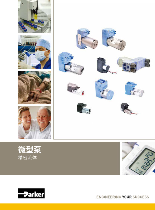
派克精密流体微型泵说明书
您与运动和控制技术领域的先行者合作,就是希望促进您的业务发展和全球的发展。
从微型电磁阀到高集成型自动化系统,我们的产品对于用于药物研发和病原体检测的救生医疗设备和科学仪器至关重要。
并且对于缩短上市时间和降低总体拥有成本也十分关键。
因此,请与派克合作,准备改变这一切吧!/precisionfluidics 1 603 595-1500目录页T2-05Helix124高效和紧凑型 13.5mm 宽泵 – 高达 800 mLPM高压泵 – 超过5.5 LPM 和高达100 PSI 的压力T2-0320高性能与尺寸比率泵 – 高达2.5 LPMLTC 系列76液体系列传送泵 – 高达 650 mLPMEZ 底座92振动隔离安装系统小型活塞泵(空气)微型泵(空气/气体)微型泵(液体)T2-0494超紧凑型、高效泵 – 高达 7.5LPMBTC-IIS 系列62应用广泛的多功能双头泵系列产品 – 高达 11 LPMBTC 系列52应用广泛的多功能泵系列产品 – 高达6 LPMLTC-IIS 系列84液体系列双头传送泵 – 高达1.5 LPMCTS 系列BTX-Connect 2836高性能紧凑型 20 mm 宽泵 – 高达 2.5 LPM多功能双头和单头泵系列,适合多种应用-高达10 LPMTTC 系列74紧凑、高效、低压泵 – 高达 6 LPMTTC-IIS 系列84紧凑、高效、低压双头泵 - 高达 11 LPM附件4Helix 微型高压泵高达100 PSI (6.9 bar)压力Parker Helix 是一款紧凑型高压泵,旨在实现小型即时临床护理仪器。
Helix 可在挑战性的高海拔环境和无法使用外部压缩空气的应用中实现高压操作。
Helix 泵可提供5.5 LPM 以上的流量和高达100 PSI (6.9 bar)的压力,为性能至关重要且空间有限的台式诊断设备提供了出色的解决方案。
• 集成了用于卸荷的X 阀,可实现高压重启• 内部飞轮可在高压下低速运行• 无油活塞• 简单的安装特性• 带有推入式接头的快速流体连接• 符合RoHS 指令和REACH 标准产品特性• 液上空气• 气动驱动•微流控芯片• 即时临床护理检验• 分子诊断• 核酸纯化•基因组学典型应用典型市场产品规格物理特性电子5微型隔Helix 微型高压泵典型流量曲线• 曲线展示了0.080"偏移泵的流量性能• 使用5.0 Vdc 控制输入时,泵将以大约4400 RPM 的转速和高达8.5 LPM的流量的状态运行,但不建议连续工作。
2020年螺杆泵泵国内十大品牌排行榜

2020年螺杆泵泵国内十大品牌排行榜1.上海阳光泵业制造有限公司上海阳光泵业是集设计/生产/销售泵、给水设备及泵用控制设备于一体的大型综合性泵业集团,是中国泵行业的龙头企业。
总资产达38亿元,在上海、浙江、河北、辽宁、安徽等省市拥有7家企业,5个工业园区,占地面积67万平方米,建筑面积35万平方米。
上海阳光获得了“上海市质量金奖”、“上海市科技百强企业”、“上海市名牌产品”、“中国质量信用AAA 级”、“全国合同信用等级AAA级”、“质量、信誉、服务三优企业”、“中国最具竞争力的商品商标”、“五星级服务认证”等荣誉,连续多年入选全国机械500强。
高端人才和高素质的员工队伍是阳光发展的动力。
集团现有员工4500余人,其中工程技术人员500多名,主要由国内知名水泵专家教授、博士硕士、中高级工程师、高级工艺师组成,形成了具有创新思维的梯队型人才结构。
科技创新,是阳光基业长青的生命之源。
集团是上海市高新技术企业、上海市知识产权示范企业和上海市专利示范企业。
上海市级的“企业技术中心”,每年以销售总额的5%,用于技术创新和新产品研发。
2.上海科雷流体自控设备制造有限公司~上海科雷流体自控设备制造有限公司是国内一家集研制、开发、生产、销售、服务于一体的企业,坐落于美丽的东方国际大都市上海。
公司主要产品有系列无负压供水设备.全自动智能成套给水设备.各式水泵.控制柜.污水提升设备及油水分离设备等各产品经国家相关产品检测中心检测都已到达国家相关标准。
公司将继续保持和发扬企业的优良传统秉着"诚信.务实.专业.创新"的经营理念真诚希望与各界精英精诚合作携手共进共创辉煌!3.北京润弘伟业科技有限公司北京润弘伟业科技有限公司是一家从事纯进口高端污水提升系统及污水泵的专业性企业。
产品及服务涵盖别墅污水提升装置、会所污水提升装置、酒店污水提升装置、办公楼污水提升装置、商chang污水提升装置、机场、地铁污水提升装置、市政小区污水提升泵站等领域。
SWIRLFLO 冷水泉源与 FLEXI-GUARD 和 ezH2O 瓶子填充器说明书
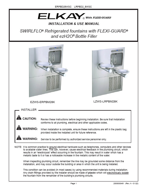
INSTALLATION & USE MANUALSWIRLFLO® Refrigerated fountains with FLEXI-GUARD NOTE: It is common practice to ground electrical hardware such as telephones, computers and other devices to available water lines. This can, however, cause electrical feedback in the plumbing circuit, whichFigure 4 - Fountain InstallationFigure 5 - Lower Panel Installation8. Install fountains with (8) 5/16-18 HHMS & (8) 5/16-18 nuts (provided) (Fig. 4). Connect the ¼” water lines from each fountain to the remaining openings on the tee at the remote chiller (cut lines to fit as needed).9. Attach waste tubes (1-1/4” O.D.) to 1-1/4” O.D. slip trap. Trap on the bottle filler side must be 1-1/2” O.D. (provided by others).10. Make final water supply connections.11. These products are designed to operate on 20-105 PSI supply line pressure. If inlet pressure is above 105 PSI, a pressure regulator must be installed in the supply line.(Caution: Any damage caused by connecting these products to a supply line with pressure lower than 20 PSI or higher than 105 PSI IS NOT covered under warranty.)12. Make electrical connections to the bottle filler and remote chiller. The LCD Bottle counter should illuminate.13. V erify proper dispensing from the bottle filler by placing a cup, hand or any opaque object in front of sensor area and verify water dispenses. Note: the first initial dispenses might have air in the line which may cause a sputter. This will be eliminated once all air is purged from the line. A steady stream of water assures all air is removed. The sensor has a 20 second maxi mum ON time. It may be necessary to step away from the beam a few times to purge all air. Check for leaks.14. Check stream height from bubbler. Stream height is factory set for 35 PSI supply. If supply pressure varies greatly from this, remove push button (Item 7 - Fig. 8) and adjust the screw on the regulator (Item 8 - Fig. 8). To remove push but ton, remove setscrew from bottom of sleeve (Item 21). Insert a small punch in screw hole and push up while grasping the push button and pull forward removing the push button. Clock wise adjustment will raise stream height and counterclockwise movement will lower stream height. For best adjustmentstream should hit basin approximately 6-1/2” from the bubbler. Reassemble the push button by pushing in on button until the push button catches in the sleeve. Reinstall the setscrew (Item 21) in the sleeve (Item 6). 15. Install the cover plates.16. Install the bottom panel, tighten screws (Fig. 4).17. Optional: Mount optional panels. Slide tongue of panel under edge of already installed panel. Tighten screws.201817162423View From Rear5NOTE:When installing replacement bubbler and pedestal (Fig. 6), tighten locknut only to hold parts snug in position. Do Not overtighten.Figure 6 - Flexi-Guard ®Bubbler DetailsBasin 1Locknut2326Reset SwitchBack Panel28,29,30,31,32Figure 7 - Fountain Body AssemblyFigure 8 - Push Button Assembly67821293121941052222See Fig. 6MAIN BOARDI.R. BOARDLED BOARDFOUR PIN CONNECTORFIVE PIN CONNECTORVERIFY CONTROL BOARD SOFTWARE1) To verify the software program of the control board the unit willneed to be shut down and restarted. The chiller (if present) does not need to be shut down and restarted.2) Shut down the unit by unplugging the power cord from the walloutlet or switching off the circuit breaker to the unit.3) R estart the unit by plugging the power cord back into the walloutlet or by switching on the circuit breaker to the unit.4) Upon start up, the bottle count display will show the softwaredesignation of BF11 or BF12.ACCESSING THE PROGRAMMING BUTTON1) To access the program button, remove #8-32 screw, pull backcover plate on lower fountain arm (Fig. 4). Reset button is located above fountain arm.RESET THE FILTER MONITOR1) Instructions apply to filtered units only.2) Depress the program button for approximately 2 seconds untilthe display changes then release. The display will change andscroll through two messages:“RST FLTR” – Reset Filter Monitor“SETTINGS” – System Settings Sub MenuIf the program button is not pushed again the display will scrollthrough the two messages above for three cycles and then default back to bottle count and be back in run mode.3) When the display changes to “RST FLTR”, depress the buttonagain. The display will change to show “FLTR =”. Depress thebutton again and the display will show “FLTR =0”4) The Green LED should be illuminated indicating that the visualfilter monitor has been reset.SETTING RANGE OF THE IR SENSOR WHERE APPLICABLE 1) Depress the program button for approximately 2 seconds untilthe display changes then release. The display will change andscroll through two messages:“RST FLTR” – Reset Filter Status LED“SETTINGS” – System Settings Sub MenuIf the program button is not pushed again the display will scrollthrough the two messages above for three cycles and then default back to bottle count and be back in run mode.2) When the display changes to “SETTINGS”, depress the buttonagain. The display will change to show“RNG SET” - Range set for IR sensor.“UNIT TYP” - Type of unit (REFRIG or NON-RFRG)“FLT SIZE” - Select filter capacity“RST BCNT” - Reset bottle count3) W hen display shows “RNG SET” push program button once the display will show current value (can be 1 – 10) e.g. “RNG = 3”.4) Once display shows current value push the program button toscroll through value of 1 – 10. Select the desired range setting, "1" being closest to sensor and "10" being farthest away.5) Once range is selected allow approximately 4 seconds to pass and then the display will go back to bottle counter and be in run mode.6) T est bottle filler by placing bottle or hand in front of sensor tomake sure water is dispensed.SETTING UNIT TYPE1) Depress the program button for approximately 2 seconds until the display changes then release. The display will change and scroll through two messages:“RST FLTR” – Reset Filter Status LED“SETTINGS” – System Settings Sub MenuIf the program button is not pushed again the display will scrollthrough the two messages above for three cycles and then default back to bottle count and be back in run mode.2) When the display changes to “SETTINGS”, depress the button again.The display will change to show“RNG SET” - Range set for IR sensor.“UNIT TYP” - Type of unit (REFRIG or NON-RFRG)“FLT SIZE” - Select filter capacity“RST BCNT” - Reset bottle count Continued from below:3) W hen display shows “UNIT TYPE” push program button once thedisplay will show current value. C an be REFRIG or NON-RFRG4) Push button once to change value. Once value is s elected the display will show the new value. (Can be REFRIG or NON-RFRG) “REFRIG“ - stands for refrigerated product. In this setting the flow rate is estimated at 1.0 gallon per minute.“NON-RFRG“ - stands for nonrefrigerated product. In this setting theflow rate is estimated at 1.5 gallons per minute. Both “REFRIG“ and“NON-RFRG“ simulate 1 bottle equal to 20 oz.5) A llow approximately 4 seconds to pass and the display will return to bottle counter and be in run mode.RESETTING BOTTLE COUNT1) Depress the program button for approximately 2 seconds until thedisplay changes then release. The display will change and scrollthrough two messages:“RST FLTR” – Reset Filter Status LED“SETTINGS” – System Settings Sub MenuIf the program button is not pushed again the display will scroll through the two messages above for three cycles and then default back to bottle count and be back in run mode.2) When the display changes to “SETTINGS”, depress the button again. The display will change to show:“RNG SET”- Range set for IR sensor.“UNIT TYP” - Type of unit (REFRIG or NON-RFRG)“FLT SIZE” - Select filter capacity“RST BCNT” - Reset bottle countIf the button is not pushed again the display will scroll through the four messages above for three cycles and return to run mode.3) W hen display shows “RST BCNT” push program button once thedisplay will show current value, e.g. “0033183”.4) Once display shows current value push the program button once more to reset back to 0. The display will show BTLCT = 0 for approximately 2 seconds and then return to run mode showing 00000000 bottles. NOTE: Once the bottle count is reset to zero there is no way to return to the previous bottle count.5) T esting the bottle counter:REFRIG units: Place bottle or hand in front of sensor for approximately9 seconds to see bottle counter count 00000001,(This is based on filling a 20 oz. bottle).NON-RFRG units: Place bottle or hand in front of sensor for approximately 6 seconds to see bottle counter count 00000001,(This is based on filling a 20 oz bottle).SETTING FILTER CAPACITY1) Depress the program button for approximately 2 seconds until thedisplay changes then release. The display will change and scroll through two messages:“RST FLTR” – Reset Filter Status LED“SETTINGS” – System Settings Sub MenuIf the program button is not pushed again the display will scroll through the two messages above for three cycles and then default back to bottle count and be back in run mode.2) When the display changes to “SETTINGS”, depress the button again. The display will change to show:“RNG SET“- Range set for IR sensor.“UNIT TYP“ - Type of unit (REFRIG or NON-RFRG)“FLT SIZE” - Select filter capacity“RST BCNT“ - Reset bottle countIf the button is not pushed again the display will scroll through the four messages above for three cycles and return to run mode.3) W hen display shows “FLT SIZE” push program button once. The display will show current value. Can be 3000GAL or 6000GAL.4) Push program button again to display the desired “FLT SIZE”.5) Allow approximately 4 seconds to pass and the display will return tobottle counter and be in run mode.BF11 - BF12 PROGRAM SETTING THE CONTROL BOARDMOUNTING FRAMEMAIN PANELDRAINLOCATIONSLOWER PANELREMOTE CHILLERFILTER (OPTIONAL)MOUNTINGFRAME Figure 9Fig. 103/8”Water InletFilter Head Assembly used after 01/01/202121JUNCTIONBOX27NOTE: Bottle filler back cover removed from the view for clarityWATERSENTRY ® PLUS FILTER PARTS LIST(See Fig. 10)ITEM NO.PART NO.DESCRIPTION1251300C 51469CFilter Assy-3000 Gal.Assy-Filter & Brkt includes Fltr Head/Mtg Brkt/John Guest Fittings/Screws1Figure 11 – Water Supply ConnectionsStream Regulator: flow as in Step 14 of the installation instructions. If NOTE: WATER FLOWDIRECTION SERVICE STOP (NOT FURNISHED)23456756073C 28708C 28473C 45767C 28343C 45781C 98871C Kit - Bubbler Assy Basin - Swirlflow Lower Shell Fountain Body Cover Plate SleeveKit - Swirlflo Pushbutton/Spring PARTS LISTITEM NO.PART NO.DESCRIPTION。
ALL-FLO气动隔膜泵A200-BAA-SSPE的技术特点
奥弗ALL-FLO隔膜泵的技术特点:
苏州埃立特流体设备有限公司专业为客户提供高品质进口化工泵。
1.全塑料材质的气阀结构,无任何金属材质部件,无需担心膜片破损造成流体腐蚀气阀部件的现象;
2.独特的气阀设计结构,无需担心因压缩空气不干净而导致停机;
3.由自润滑材质做成的梭式机械结构主气阀,摩擦系数小,无需添加任何润滑油;
4.无通风孔设计的气阀系统,避免了腐蚀性气体造成的气阀腐蚀,且保证运行畅通无死点;
5.高技术的密封,在不干净及较湿的气体进入时,气阀仍然可以工作。
使用唇封技术及高耐磨性橡胶大大延长了使用寿命;
6.选用更优质的PTFE材质隔膜,不需要降低隔膜的冲程次数,从而损失20%的流量,而其他品牌都需这么做。
且所以PTFE隔膜的背衬隔膜都是Santoprene 材质,同样具有抗腐蚀性,被称为“二级防护”。
美国IDEX泵业集团帕斯菲达公司 Chem-Tech 隔膜计量泵 说明书

Chem-Tech 隔膜计量泵
使用说明书
帕斯菲达计量泵
本篇中文稿仅供使用者参考,如有理解歧义,请以英文原稿为准。
1
目录
页数
安全说明…………………………………………………………………………… 1-2 介绍………………………………………………………………………………… 2 操作前准备………………………………………………………………………… 3 安装、布管、连接………………………………………………………………… 3-7 维护………………………………………………………………………………… 8 服务和维修………………………………………………………………………… 9 问题检修…………………………………………………………………………… 10-11 零件目录表………………………………………………………………………… 12 置换备件包………………………………………………………………………… 13
安装,管道和线路
拆卸,装配和安装
纸箱中应包含(见图 A): -- 计量泵 -- 透明吸液管 -- 白色硬回溢流管 -- 白色硬排液管 -- 注入背压阀 -- 粗滤止逆底阀 / 配重块 -- 说明书 -- 排出阀配件 -- 三通阀
图A
4
进料器可以安装在墙上的托架上(图 B),槽架平台上(图 C),垂直于墙面(图 D),或垂直于 槽表面(图 E)。 提示:连接点必须高于溶液槽的顶部,这样可阻止因重力进料。100 系列泵的最大扬程为 70M,
5
注意:对于无排出阀操作,补充排出阀(#49 款)和 0.38"管卸压阀罩(#42 款)带 0.5" 管卸压阀罩(#42 款)和接合螺母(#43 款)。看 13 页(铜网部装配)。#42 和#43 从工厂索取。
安德里兹sf浆泵说明书

2.1. 技术说明______________________________________________________________ 11 2.1.1. 形式 _____________________________________________________________________ 11 2.1.2. 叶轮 _____________________________________________________________________ 11 2.1.3. 轴承 _____________________________________________________________________ 11 2.1.4. 轴密封 ___________________________________________________________________ 11 2.1.5. 材料 _____________________________________________________________________ 11 2.1.6. 部件清单 SF 100-250________________________________________________________ 12 2.1.7. 部件清单 SF 125-280________________________________________________________ 14 2.1.8. 部件清单 SF 100-350________________________________________________________ 16 2.1.9. 部件清单 SF 150-300________________________________________________________ 18
ALL-FLO操作手册1

ALL-FLO隔膜泵操作手册第一部分:注意事项—必先阅读各种材质耐温极限:接液部件:聚丙烯(PP)聚偏二氟乙烯(PVDF)导电尼龙(Conductive Nylon)0℃~ 65℃-12℃~93℃-17℃~ 65℃32℉~150℉10℉~225℉0℉~150℉尼龙(Nylon)弹性体:-12℃~ 65℃10℉~150℉三道橡胶(Santoprene)氟橡胶(Viton)Geolast®聚四氟乙烯/特氟龙三元乙丙橡胶(EPDM)-12℃~ 100℃-4℃~100℃-12℃~82℃4℃~100℃-40℃~100℃10℉~212℉-20℉~212℉10℉~180℉40℉~212℉-40℉~212℉*通过选择不同的弹性体可以改变温度限度。
注意:当选择泵的材质时,一定要检查所有接液部件的温度限度。
如氟橡胶的最高温度限度为100℃(212℉),而聚丙烯的最高温度限度只有65℃(150℉)。
注意:操作泵的时候需配带安全防护眼镜。
当发生膜片碎裂时,可能会从气体出口冲出。
警告:防止静电火花——如果有静电火花产生,有可能会引起火灾或爆炸。
当输送的易燃性液体无论何时都有可能释放静电时,泵、阀及容器的正确接地就变得至关重要了。
注意:ALL-FLO全系列的隔膜泵,供气压力不得超过8.2bar(120psig)。
注意:ALL-FLO的聚丙烯(PP)塑料泵是由天然聚丙烯制成,应避免长时期的日光照射,否则可引起塑料的降解。
第二部分:安装及操作A.安装:①进行维护与检修前,应拆除连于泵上的压缩气体管道并将泵内所有的气体排出。
拆开所有入口、出口及空气管道,将泵倒置并用适宜容器盛装泵内流出的液体。
②在安装空气管道之前,最好用压缩空气将管道吹10至20秒以保证所有的管道碎片均被除净,且最好在隔膜泵泵的压缩空气入口加装空气两联件(调压、过滤),最好保证过滤精度大于25微米。
③安装前旋紧所有的螺栓,因为在运输过程中安装好的螺栓有可能会松动。
无锡中康流体科技有限公司 E,CE 系列端吸离心泵 安装、操作及维护手册说明书
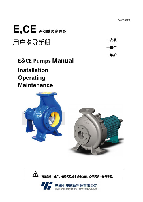
V5658120E,CE系列端吸离心泵用户指导手册E&CE Pumps ManualInstallation Operating Maintenance请在安装、操作、使用和维修本设备之前,必须阅读本指导手册。
—安装 —操作 —维护E,CE系列端吸离心泵安装、操作及维护手册目录1概要 (5)1.1注意事项 (5)1.2 免责声明 (5)1.3保证 (5)1.4 安全 (5)2运输和存放 (5)2.1货物接收和拆包 (5)2.2吊运 (6)2.3 储存 (6)3产品介绍 (7)3.1型号说明 (7)3.2结构 (7)3.3性能 (7)4 安装 (7)4.1 安装位置 (7)4.2 零件装配 (7)4.3灌浆 (8)4.4联轴器对中 (8)4.4.1检查和调整对中的要点 (8)4.4.2对中测量方法 (8)4.5管道连接 (9)4.5.1吸入管道 (9)4.5.2排出管道 (9)4.5.3辅助管道 (9)4.5.4 最终检查 (10)4.6 最终轴对准检查 (10)4.7 电气连接 (10)5 试车、启动、运行和停机 (10)5.1 试车前步骤 (10)5.1.1 润滑 (10)5.1.2旋转方向 (10)5.2启动泵 (10)5.3运行泵 (11)5.4 停止和关机 (11)6 维护及维修 (11)6.1概述 (11)6.2 检查计划 (11)6.2.1 例行检查(每日/每周) (11)6.2.2 定期检查(每6个月) (12)6.3 备件 (12)6.3.1 备件订购 (12)6.3.2 备件的存放 (12)6.4 推荐的备件 (12)6.5 所需工具 (12)6.6 紧固件扭矩 (13)6.7 拆卸 (13)6.8 装配 (13)7故障原因及纠正措施 (14)8零件清单及图纸 (15)8.1装配结构图及零件清单 (15)8.2爆炸零件图及零件清单 (16)9增补信息 (17)E,CE系列端吸离心泵安装、操作及维护手册1概要该指导手册必须存放在产品的运行位置附近,或者与产品存放在一起。
- 1、下载文档前请自行甄别文档内容的完整性,平台不提供额外的编辑、内容补充、找答案等附加服务。
- 2、"仅部分预览"的文档,不可在线预览部分如存在完整性等问题,可反馈申请退款(可完整预览的文档不适用该条件!)。
- 3、如文档侵犯您的权益,请联系客服反馈,我们会尽快为您处理(人工客服工作时间:9:00-18:30)。
锂离子电池的电极制造,正极浆料由粘合剂、导电剂、正极材料等组成;负极浆料则由粘合剂、石墨碳粉等组成。
正、负极浆料的制备都包括了液体与液体、液体与固体物料之间的相互混合、溶解、分散等一系列工艺过程,而且在这个过程中都伴随着温度、粘度、环境等变化。
苏州埃立特流体设备有限公司专业为客户提供高品质进口化工泵。
浆料在输送过程中所使用的包含输送泵、过滤装置、分散装置、储料罐等。
考虑到浆料输出的稳定性会对集流体涂布等环节有重要的影响,所以选择输送泵时要选择动力稳定的输送设备,通常所使用的是All-Flo隔膜泵。
All-Flo隔膜泵的特点:
1、阀芯由自润滑材料Acetal(乙缩醛)做成梭形结构,让它的机械摩擦降到最低,所以无需额外添加润滑油;
2、气阀组件数量少,备件更换费用较低;
3、无通风孔设计,且阀芯为乙缩醛材质,使其能忍受较“脏”和“湿润”的气源;
4、塑料泵的中间体均为聚丙烯材质,即使膜片破裂,也不担心输送的酸碱性物
料腐蚀中心腔体;
5、也不用担心使用环境中酸雾或碱雾的腐蚀。