球阀使用维护说明书
电动蝶阀球阀使用说明书

2.不 要在下述场所保管:
(1)有 雨水处
⑵ 超过 ω ℃的高温场所
o)灰 尘多的场所
(4)湿 度高的场所
3.验 收时因检查性能而拆开了包装必须重新包装好 ,直 到开始安装 。 4.空 气配管接 口及 电气配线接 口的塞子和盖等 ,在 空气配管工程及 电气配线工程开始 以前 ,
请 不要打开 。
5.对 于使用后再进行保管 的情况 ,请 按下述事项进行处理 :
‘
紫请预 留进线 ,手 动 时所需的空 间;
来注意 :室 外 阳光直射会造成高温 ,加 速元器件 的老化 ,甚 至失效 ;
雨水会加速胶垫 的老化 ,并 在万一防水操作不 当时,瞬 间损坏产 品;
环境温度 、流体温度条件
紫环境温度应在-25℃ ~60℃ 范 围 内;
注意 :在 零度 以下使用 时,应 使用带有 防止结露 的除湿加热器 的机 型;
可实现各种腐蚀性 、非腐蚀性 的气体 、液体 、胶状体 、颗粘物 的流量控制 。
★ 其安装与维修需注意 :
1.蝶 阀可 以安装在空 间任意角度管路上 。
2.安 装位置必须保证使用维修更换方便 。
3.允 许双 向使用 ,可 换 向使用 (安 装 时无方 向要求 )。
4.购 回阀门后将蝶 阀开启 务50,置 于室 内干燥处存放 。
★ 性能特 点:
⒈ 功能强劲 一△智能型、比例式 、开关式 、各类信号输 出型应有尽有 ;
⒉ 体积小巧一∵体积仅相当于同类产品的 35%左右: 3.轻便宜人——重量仅相当于同类产品∷的 30%左右; 4.美观大方——铝合金压铸外壳,精 细流畅、且可减少电磁干扰;
5,安 全保证——通过 AC!sO0V耐 压检测,F级 绝缘电机,安 全有保障; ⒍ 酡套简∷单——采用单相电源、外接线路简单,也 可做 3sOV直流电源;
球阀—产品使用说明书

Ball valves球阀使用说明书Ball Valve Operating Manual浙江石化阀门有限公司Zhejiang Petrochemical Valve Co., Ltd.二O一一年 Year 2011一用途Application球阀是一种管线阀门产品,用于接通或截断管路中的介质。
一般是处于全开或全关状态,在微开状态下可作流量的调节使用。
广泛适用于工况条件下水、气、油品等介质的各种管路中。
Ball valve is pipeline valve, used for connecting or cutting off medium in the pipelines. Normally it is at the state of opening or closing. And it couldfunction as regulating the flow when it is at the state of slightly open. It isused on the pipeline such as water, gas, oil etc.二性能规范 Performance Specification压力等级: Class150; Class300; Class600;Pressure: Class150; Class300; Class600;公称尺寸:NPS 2 ~NPS24;Nominal Size: NPS 2 ~NPS24阀体材料: ASTM A216 WCB; ASTM A351 CF8;Body Material:ASTM A216 WCB;ASTM A351 CF8;产品的设计、制造按API6D的规定;检查试验按API6D的规定;法兰连接尺寸按 ASME 的规定;结构长度按API6D的规定;Designed and manufactured according to API6D; Inspected and tested accordingto API6D;Flange ends according to ASME ; Face to face according to API 6D适用介质:水、蒸汽、油品等。
世伟洛克 SK系列 多用途球阀 说明书

A-76 球阀A多用途球阀SK 系列■ 工作压力可达 6000 psig (413 bar)■ 温度范围从−40 到 150°C (−40 到 302°F)■ 使用紧凑型设计提供大流量能力■ 1/4 至 3/8 in. 和 6 至 8 mm 端接■ 316不锈钢结构SK 系列球阀 A-77A弹簧加载的■ ■ 漏密封压力—温度额定值可供应低温 SK 系列球阀。
见第 P A-79 页。
世伟洛克® (Swagelok ®) SK 系列球阀采用紧凑型设计、具有扭矩低、四分之一圈操作的特点、能够在压力最高达 6000 psig (413 bar) 的应用场合提供可靠关断。
其它特点还有:■ 流量系数 (C v ) 0.9 到 1.4■ 世伟洛克可测量卡套管接头、NPT 和 ISO 公称管以及世伟洛克外螺纹 VCO ®端接■ 标准面板安装 ■ 双向流动■ 可以使用密封成套件进行现场组装特点有关世伟洛克球阀的重要说明世伟洛克球阀设计用于全开或全闭位置。
在一段时间内未使用的阀门可能会有较高的初始启动力矩。
测试所有世伟洛克 SK 系列球阀都在工厂使用氮气在 1000 psig(69 bar) 的压力下进行了双流向测试。
阀座的最大容许泄漏率为0.1 std cm 3/min 。
壳体测试时要求用检漏液检测不到泄漏。
O 型圈阀杆密封■ ■ 清洁和包装所有世伟洛克 SK 系列球阀都是按照世伟洛克标准清洁和包装规范 (SC-10)、MS-06-62 清洁和包装的。
按照世伟洛克特殊清洁和包装 (SC-11)、 MS-06-63 进行的特殊清洁和包装作为可选项提供、以确保符合 ASTM G93 等级 C 中所规定的产品清洁度要求。
参阅第 P A-83 页的工艺选项。
卡套管数据、P G-5。
带有 VCO 管接头端接的阀的额定压力是基于与之配合的管 接头的额定值;见世伟洛克产品目录 VCO O 型圈面密封接头、P B-135。
阀门产品使用说明书

Z41H 闸阀使用阐明书Z41H闸阀为阀板在阀杆旳带动下,沿阀座密封面作升降运动而达到启闭旳目旳。
1、压力级:1.0MPa, 1.6MPa, 2.5 MPa, 4.0MPa,6.4 MPa,10 MPa;2、使用温度:-29℃---425℃3、使用介质:水、蒸汽、油品等非腐蚀性介质。
一、构造特点1、阀体通道为全通径,流体阻力小。
2、介质可从闸阀二侧任意方向流过,不受介质流动方向旳限制。
3、全开对密封面受冲蚀性较小,密封性能好。
二、维护保养 1、运送途中旳维护阀门在运送途中应注意要轻装轻卸,以避免法兰密封面磕碰损坏,应将密封面擦干净后再关闭。
要保证油漆、铭牌和法兰密封面旳完好,现场要作好防雨、防尘工作。
2、保管中旳维护对入库旳阀门,要认真擦拭、清洗阀门在运送过程中旳积水和灰尘,对容易生锈旳加工面、阀杆、密封面应涂上一层防锈剂或贴上一层防锈纸加以保护。
阀门进出口通道旳密封盖要封好,以免赃物进入。
对在运送中损坏、丢失旳阀门零件,应及时配齐。
3、阀门安装注意事项3.1、阀门搬运时要小心轻放,更不容许丢掷,以免阀杆扭断及各部件损伤。
3.2、在安装时应清除阀腔内部和管道中尘屑杂物,以避免擦伤阀体与阀板密封面,以致发生渗漏。
3.3、带传动机构旳闸阀(如齿轮传动、电动、气动或液动等)均应严格按传动机构使用阐明旳规定安装,安装位置应保证阀门旳使用,维修以便,阀门应直立安装。
3.4、阀门传动机构旳安装、使用、贮存、保管应按执行机构使用阐明书执行。
3.5、手轮、传动机构均不容许作起吊用,并严禁碰撞。
3.6、手动闸阀应靠旋转手轮使之启闭,不得借助于其她杠杆。
3.7、在操作过程中应保持介质和阀件旳清洁,发现任何缺陷和故障,应及时排除。
4、运转中旳维护阀门在运转过程中要使阀门处在常年整洁、润滑良好、阀件齐全、正常运转旳状态。
以达到启动灵活旳目旳,不容许在运营中对阀门进行敲打。
三、常用故障旳避免和排除常用故障产生因素避免措施排除措施开不起1、T型槽断裂。
电动球阀使用说明书

型
-15Y -20Y -25Y -50Y -15Q -20Q -25Q -50Q
号 Q961F Q961F Q961F Q961F Q961F Q961F Q961F Q961F
-15Y -20Y -25Y -50Y -15Q -20Q -25Q -50Q
通径(mm) φ15 φ20 φ25 φ50 φ15 φ20 φ25 φ50
故障现象
故障原因
不 能 正 常 启 动 电机过热
1、电源不通 2、电压低 3、操作回路不通 4、切换装置复位不正确 5、污物卡死 6、微动开关触点损坏 7、电容器损坏
阀启闭过度频繁
排故措施
接通电源 调整电压 检查电路 检查复位情况 清除污物 更换开关 更换电容器 按ε=10%
咸阳三星机电科技有限责任公司
咸阳三星机电科技有限责任公司
电动机。电动机通过其齿轮式减速机构驱动输出轴,输出轴通过十字接 头去驱动阀杆,阀杆驱动球体转动而实现阀的开关。
3.1.3 减速器 为一齿轮式减速器,减速比为 291.3:1 3.1.4 行程控制机构 其形式为凸轮块式。行程控制凸轮有开向和关向之分,分别通过相应 的微动开关控制开向和关向行程。即左下凸轮通过左下微动开关控制开 向行程,右下凸轮通过右下微动开关控制关向行程。球阀行程 90°。此 机构同时附有同步信号输出机构,它的左右凸轮及相应的微动开关同时 为远(近)距离控制输出阀门状态信号(见图 1)。 3.1.5 手动—电动切换装置 其形式为全手动切换装置,仅限于安装调试或电控失灵时使用。请严 格按使用说明书操作,否则将损坏内部机构。 3.1.5.1 由电动变手动的切换方法 切断电源,手用力向上拉起手柄(见图 2),然后用扳手按盖子上规定的 90°范围和方向转动传动轴(注意:绝不可超范围操作),使传动轴上的离 合销从传动齿轮的轴向槽中滑出,使之和减速器脱离,从而可以以 1:1 的传动比操作阀门的开启和关闭。 3.1.5.2 由手动变电动的切换方法 切断电源,手用力向上拉起手柄,按盖子上规定的范围和方向用扳手 转动传动轴使手柄上指针复位到原来的位置,松开手柄,使传动轴上的离
球阀使用说明书
2、阀门两端连接采用法兰结构或长焊接端,浮动球阀阀体和阀盖
连接处密封采用 PTFE 垫片。
3、阀杆采用有防飞出功能的下装结构。
4、扁式阀杆头的设计能让装配的手柄始终与流体通道平行。装配
中,应避免手柄未达到预定位置。
五、阀门运输和保管
1、阀门运输 (1)在运输过程中,应将阀门用纸箱或木箱包装。如纸箱或木箱 无法包装阀门时,应用托盘将阀门固定好,做防尘防水处理。 (2)在装载阀门时,不要让传动装置承受任何外力。 (3)避免装载设备时超载,货物摆放要宽松,避免阀门受撞击。 (4)所有的阀门搬运都应该很小心,对于大口径的阀门应该用起 吊设备。 2、阀门保管
片,可以作为修理和维护的备用零件进行订购。 8、分解及再装配时必须小心防止损伤零件的密封面,特别是非金 属零件,取出 O 型圈时宜使用专用工具。 9、分解下来的单个零件可以用浸洗方式清洗。尚留有未分解下来 的非金属件的金属件可采用干净的细洁的浸渍有清洗剂的绸布 (为避免纤维脱落粘附在零件上)擦洗。清洗时须去除一切粘附 在壁面上的油脂、污垢、积胶、灰尘等。 10、非金属零件清洗后应立即从清洗剂中取出,不得长时间浸泡。 11、清洗后需待被洗壁面清洗剂挥发后(可用未浸清洗剂的绸布 擦)进行装配,但不得长时间搁置,否则会生锈、被灰尘污染。 12、使用润滑脂润滑。润滑脂应与阀金属材料、橡胶件、塑料件 及工作介质均相容。在密封件安装槽的表面上涂一薄层润滑脂, 在橡胶密封件上涂一薄层润滑脂,阀杆的密封面及摩擦面上涂一 薄层润滑脂。
高压水密封实验压力
1.76MPa
低压气密封实验压力
0.6MPa
适用温度℃
-29~200
三、工作原理
球阀的主要功能是切断或接通管道中的流体。当手动或其它
F90系列安全全腔球阀安装与维护手册说明书
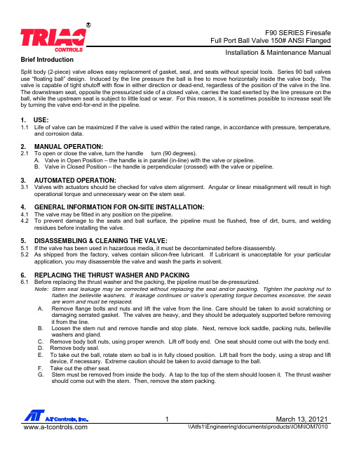
Brief IntroductionSplit body (2-piece) valve allows easy replacement of gasket, seal, and seats without special tools. Series 90 ball valves use “floating ball” design. Induced by the line pressure the ball is free to move horizontally inside the valve body. The valve is capable of tight shutoff with flow in either direction or dead-end, regardless of the position of the valve in the line. The downstream seat, opposite the pressurized side of a closed valve, carries the load exerted by the line pressure on the ball, while the upstream seat is subject to little load or wear. For this reason, it is sometimes possible to increase seat life by turning the valve end-for-end in the pipeline.1. USE:1.1 Life of valve can be maximized if the valve is used within the rated range, in accordance with pressure, temperature,and corrosion data.2. MANUAL OPERATION:2.1 To open or close the valve, turn the handle ¼ turn (90 degrees).A. Valve in Open Position – the handle is in parallel (in-line) with the valve or pipeline.B. Valve in Closed Position – the handle is perpendicular (crossed) with the valve or pipeline.3. AUTOMATED OPERATION:3.1 Valves with actuators should be checked for valve stem alignment. Angular or linear misalignment will result in highoperational torque and unnecessary wear on the stem seal.4. GENERAL INFORMATION FOR ON-SITE INSTALLATION:4.1 The valve may be fitted in any position on the pipeline.4.2 To prevent damage to the seats and ball surface, the pipeline must be flushed, free of dirt, burrs, and weldingresidues before installing the valve.5. DISASSEMBLING & CLEANING THE VALVE:5.1 If the valve has been used in hazardous media, it must be decontaminated before disassembly.5.2 As shipped from the factory, valves contain silicon-free lubricant. If Lubricant is unacceptable for your particularapplication, you may disassemble the valve and wash the parts in solvent.6. REPLACING THE THRUST WASHER AND PACKING6.1 Before replacing the thrust washer and the packing, the pipeline must be de-pressurized.Note: Stem seal leakage may be corrected without replacing the seal and/or packing. Tighten the packing nut toflatten the belleville washers. If leakage continues or valve’s operating torque becomes excessive, the seals are worn and must be replaced.A. Remove flange bolts and nuts and lift the valve from the line. Care should be taken to avoid scratching ordamaging serrated gasket. The valves are heavy, and they should be adequately supported before removing it from the line.B. Loosen the stem nut and remove handle and stop plate. Next, remove lock saddle, packing nuts, bellevillewashers and gland.C. Remove body bolt nuts, using proper wrench. Lift off body end. One seat should come out with the body end.D. Remove body seal.E. To take out the ball, rotate stem so ball is in fully closed position. Lift ball from the body, using a strap and liftdevice, if necessary. Extreme caution should be taken to avoid damage to the ball. F. Take out the other seat.G. Stem must be removed from inside the body. A tap to the top of the stem should loosen it. The thrust washershould come out with the stem. Then, remove the stem packing.7. VISUAL INSPECTION:7.1 Clean and inspect metal parts. It is not necessary to replace neither ball nor stem unless the surface has signs ofabrasion or corrosion. We strongly recommend replacement of all soft parts whenever the valve is disassembled for reconditioning. We provide replacement kits that contain all the replaceable parts.Note: The valve may be assembled and operated dry with any lubricant. However, a light lubrication will aid inassembly and reduce initial operating torque. Lubricant used must be acceptable with the intended line fluid.8. ASSEMBLYInstall one seat in the body cavity with the spherical curvature facing the ball.8.1 Install the thrust washer on stem and slide the stem up through the body. Install packing, gland, belleville washers,locking saddle. Screw the packing nut into the stem. Lock the saddle in place.8.3 Install stop plate, handle and washer. Screw the stem nut into the stem until the handle is secure.8.4 Turn handle to the closed position. Line up the ball slot with the stem end and slide the ball into position. Turn thehandle to the open position to hold the ball in place. 8.5 Install the remaining seat into body side.8.6 Put body seal gasket into body and line up end flange. Because the body flange bolt pattern is different from the lineflange bolt pattern, it is possible to assemble the valve such that the line flanges bolt pattern don’t line up. Be certain to align end flanges bolt holes to straddle valve center lines. Be careful not to damage body seal when putting cap end into body.8.8 Install cap end nuts and tighten in the “star” pattern to the proper torque. Extreme care must be exercised duringadjustment of cap end nuts to make sure that complete engagement of the studs with body flange is maintained. There should be at least one stud thread exposed on each side.8.9 Cycle the valve slowly, with a gentle back and forth motion, to build gradually to the full quarter turn. By cyclingslowly, the seat lips will assume a permanent seal shape against the ball. A fast turning motion, at this point, may cut the seats before they have a chance to form the proper seal.8.10 Test valve, if possible, prior to placing valve back into line position. If not properly secured, the valve can separatefrom the pressure source, resulting in possible injury. Always join the valve to companion flanges of same pressure rating as valve and secure with a full set of flange bolts.TEST AS FOLLOWS:A. Secure valve to a test fixture by means of a mating flange with full bolting and a suitable gasket. Orient valve soseat to be tested is facing up.B. Introduce 50 to 100 psig air. Partially cycle the valve, under pressure, then slowly close to make sure the cavity ispressurized (use hearing protection). Pour water into the upper port to cover the ball and visually check for bubbles. If bubbles appear, pour the water out, cycle the valve several times and recheck. To check for leakage in the other port, reverse the valve and introduce air pressure to the port just checked.C. Check stem seal at this time by coating the stem top area with a water/soap solution. If leakage occurs, tighten stemseal just until leakage stops.Valve SizeBreak Away Torque(In-lbs.)Torque of Body Bolts(In-lbs.)Torque of Stem Nut(In-lbs.)½” 92 95 ~ 130 87 ¾” 115 122 ~ 156 87 1” 150 365 ~ 399 130 1-1/2” 320 365 ~ 399 208 2” 415 365 ~ 399 208 2-1/2” 675 365 ~ 399 208 3” 1000 477 ~ 521 304 4”1800477 ~ 521304A-T Controls product, when properly selected, is designed to perform its intended function safely during its useful life. However, the purchaser or user of A-T Controls products should be aware that A-T Controls products might be used in numerous applications under a wide variety of industrial service conditions. Although A-T Controls can provide general guidelines, it cannot provide specific data and warnings for all possible applications. The purchaser / user must therefore assume the ultimate responsibility for the proper sizing and selection, installation, operation, and maintenance of A-T Controls products. The user should read and understand the installation operation maintenance (IOM) instructions included with the product, and train its employees and contractors in the safe use of A-T Controls products in connection with the specific application.While the information and specifications contained in this literature are believed to be accurate, they are supplied for informative purposes only. Because A-T Controls is continually improving and upgrading its product design, the specifications, dimensions and information contained in this literature are subject to change without notice. Should any question arise concerning these specifications, the purchaser/user should contact A-T Controls.For product specifications go to /A-T Controls, Inc. • 9955 International Boulevard, Cincinnati, OH 45246 • Phone: (513) 530-5175 • Fax: (513) 247-5462 • 。
ATControls高性能寒冷球阀C8 CR系列3部分全端口 普通端口阀门安装与维护手册说明书

Contents1.SCOPE (2)2.INSTALLATION (2)3.VALVE OPERATION (3)4.DISASSEMBLY (4)5.ASSEMBLY (4)6.REPAIR KITS (5)7.BILL OF MATERIALS (6)1.SCOPE1.1. CAUTION1.1.1. F or your safety, read this manual before installation or service.1.1.2. B efore installing or servicing, please ensure the line pressure has been relieved and any hazardous fluidshave been drained or purged from the system.1.1.3. E nsure that all Lockout and Tagout procedures for the system have been properly implemented.1.2. USE1.2.1. M aximum results and long life of valves can be maintained under normal working conditions and according topressure/ temperature ratings and corrosion data chart.2.INSTALLATION2.1. GENERAL INFORMATION FOR INSTALLATION2.1.1. When installing the cryogenic valve, the gradient for the extended bonnet can not be greater that 45 degreesas the following illustration. This is to avoid flooding at the top of the gland packing which can cause valvefailure.2.1.2. A s the cryogenic valve is unidirectional, it is required to make sure the direction of the arrow mark on the bodymatch the flow of the pipeline when installing the valve. The vented hole of the ball will be upstream when thevalve is closed.2.2. INSTALLATION OF THREADED VALVES2.2.1. U se conventional sealant, such as hemp core, Teflon, etc. on threads. Apply wrench only on the hexagon ofthe valve ends. Tightening by using the valve body or lever can seriously damage the valve. In someapplications, screwed valves are back welded on site. These valves must be treated as per instructions forthe weld end valves before back welding.2.3. INSTALATION OF WELDED ENDS2.3.1. T ack weld the valve on the pipe in four points on both end caps.2.3.2. W ith the valve in the open position, (lever to be parallel to the axis of the pipe), remove all the body boltsexcept one. Loosen the nut on the remaining bolt. Swing the body outside the pipe. Finish welding both endcaps on the pipe.2.3.3. Take out PTFE gaskets from body, emded new graphite gasket groove of body•Note: Weld-End valves contain PTFE joint gaskets for temporary purposes only; the provided graphite joint gaskets shall be used in place of the PTFE joint gaskets for final installation.2.3.4. W hen cooled down, clean both end caps and body surface.2.3.5. S wing the body back in position and replace the body bolts. Tighten all nuts slightly. This operation is veryimportant to keep the body and end caps perfectly parallel, thus preventing distortion of end caps. Tightenbody bolts evenly (see section 5.5) Make sure that the maximum tightening torque is observed. Check properoperation of the valve.3.VALVE OPERATION3.1. MANUAL3.1.1. H ANDLE3.1.1.1. To OPEN the valve, turn the handle counterclockwise until the handle is parallel with the pipelineand the handle has contacted the handle stop.3.1.1.2. To CLOSE the valve, turn the handle clockwise until the handle is perpendicular with the pipelineand the handle has contacted the handle stop.3.1.1.3. A handle lock is incorporated into the handle. To use, slide the lock into the mounting pad, in thefull open or full closed position. Insert an appropriate size lock or hasp into the handle. If it can beperformed safely, try to turn he handle to ensure the valve has been locked properly.3.1.2. G EAR3.1.2.1. To OPEN the valve, turn the handle wheel counterclockwise. The indicator will be pointing to theopen position and stop rotating when fully open. The flow can be adjusted by stopping the indicatoranywhere between open and close.3.1.2.2. To CLOSE the valve, turn the handle wheel clockwise. The indicator will be pointing to the closeposition and stop rotating when fully closed. The flow can be adjusted by stopping the indicatoranywhere between open and close.3.1.3. A UTOMATED3.1.3.1. A-T Controls Cryogenic High Performance Three-Piece Full Port or Regular Port Ball Valves canbe mounted with quarter-turn actuators. Valves with actuators shall be checked for proper valve stemalignment. Angular or linear misalignment may result in high operational torque and unnecessary wearon the valve stem. See the actuator IOM for information on operating the actuator.4.DISASSEMBLY4.1. Remove actuator or gear if equipped.4.2. Care should be taken to not damage the surface finish of the valve components.4.3. Remove the end caps (2) from the body (1) by removing the body bolts (17) and bolt nuts (18).4.4. Remove the seats (4) and body gasket (5) from both sides of the body (1). Once removed, with the valve in thefully closed position, the ball (3) should slide freely out of the body (1).4.5. If equipped, remove the handle nut (27), and handle stop assembly (15).4.6. While holding the stem (10) stationary, remove the packing nut (13). Once removed, the locking saddle (12),Belleville washers (19), and packing bushing (11) should be free to remove.4.7. Remove the extended bonnet (26) and stem (10) through the top of the valve.4.8. Remove the packing set (9) and thrust washer (8).4.9. Inspect all components for damage and, if necessary, clean or replace.5.ASSEMBLY5.1. Care should be taken to not damage the surface finish of the valve components.5.2. Install extended bonnet (26). Place thrust washer (8) on the stem (10) and install stem (10) by going through theextended bonnet (26). Insert the packing set (9) over stem (10).5.3. Install packing gland (9), Belleville washers (19), locking saddle (12), and packing nut (13). While holding the stem(10), tighten the packing nut (13) to the torque listed in the Fastener Torque Chart below. Tighten further if neededin order to be able to place the locking saddle (12) over the packing nut (13).5.4. Ensure the stem (10) is in the closed position with the body tang parallel with the flow of the valve. Insert a seat(4) and body gasket (5) in one side of the body (1). Carefully slide the ball (3) into the body (1) making sure thevent hole of the ball (1) is upstream of the valve. Insert the other seat (4) and other body gasket (5).5.5. Assembly ends (2) onto body (1). Insert all body bolts (17) and nuts (18) into the valve and tighten to finger tight,making sure that the ends (2) are flat against the body (1). Tighten all body bolts (17) from the nut (18) to the final torque in a star pattern. Check each body bolt (17) torque and tighten if needed a final time. It is acceptable for the torque to relax slightly over time due to relaxation of the polymer components, but the valve will still seal properly.If leakage is detected, repeat the steps for tightening the body bolts (17).5.6. If required, assembly the handle stop (15), handle (14), and the handle nut (27).6.REPAIR KITSRepair kits are available to replace all soft goods. See Bill of Materials for components that are included in the repair kits.7. BILL OF MATERIALSA-T Controls product, when properly selected, is designed to perform its intended function safely during its useful life. However, the purchaser or user of A-T Controls products should be aware that A-T Controls products might be used in numerous applications under a wide variety of industrial service conditions. Although A-T Controls can provide general guidelines, it cannot provide specific data and warnings for all possible applications. Thepurchaser / user must therefore assume the ultimate responsibility for the proper sizing and selection, installation, operation, and maintenance of A-T Controls products. The user should read and understand the installation operation maintenance (IOM) instructions included with the product and train its employees and contractors in the safe use of A-T Controls products in connection with the specific application.While the information and specifications contained in this literature are believed to be accurate, they are supplied for informative purposes only. Because A-T Controls is continually improving and upgrading its product design, the specifications, dimensions and information contained in this literature are subject to change without notice. Should any question arise concerning these specifications, the purchaser/user should contact A-T Controls. For product specifications go to https:///Downloads/A-T Controls, Inc. • 9955 International Boulevard, Cincinnati, OH 45246 • Phone: (513) 530-5175 • Fax: (513) 247-5462 • 。
- 1、下载文档前请自行甄别文档内容的完整性,平台不提供额外的编辑、内容补充、找答案等附加服务。
- 2、"仅部分预览"的文档,不可在线预览部分如存在完整性等问题,可反馈申请退款(可完整预览的文档不适用该条件!)。
- 3、如文档侵犯您的权益,请联系客服反馈,我们会尽快为您处理(人工客服工作时间:9:00-18:30)。
球阀使用维护说明书
一、引言
球阀作为常见的流体控制装置,广泛应用于各类液体和气体的输送系统中。
本说明书旨在向用户提供球阀的使用和维护指南,以确保球阀的正常运行和延长其使用寿命。
二、球阀的基本结构
球阀由阀体、阀盖、球体、密封圈、阀杆、手柄等组成。
阀体内部设有球体,通过旋转球体实现流体的开启和关闭。
三、球阀的使用方法
1. 开启球阀:顺时针旋转手柄,使球体与阀体内孔对齐,流体可顺利通过。
2. 关闭球阀:逆时针旋转手柄,使球体与阀体内孔不对齐,流体被阻断。
四、球阀的注意事项
1. 在操作球阀前,请确认设备上已经停止了流体的运输,并
且系统内的压力已经释放干净。
2. 请勿用过大力气旋转手柄,以免损坏球阀的密封圈。
3. 如果球阀长时间未使用,建议定期旋转手柄,以保持其灵
活性。
4. 在高温或高压环境下使用球阀时,应根据实际情况选择合
适的材质和密封圈,以确保其正常运行和密封性能。
5. 球阀的连接方式有螺纹连接、焊接连接、法兰连接等,请
根据实际需要选择合适的连接方式。
五、球阀的维护方法
1. 维护前请关闭球阀,并确认系统内的压力已经释放干净。
2. 定期检查球阀的密封圈,如有磨损或老化,请及时更换。
3. 使用球阀时,避免频繁开启和关闭,以减少球阀的磨损。
4. 定期对球阀进行清洁和润滑,以确保其灵活性和正常运行。
5. 注意防止球阀与其他物体发生碰撞,避免损坏阀体和球体。
六、球阀的故障排除
1. 当球阀无法旋转或旋转困难时,可能是球阀内部有异物堵塞,请及时清理。
2. 当球阀无法完全密封时,可能是密封圈磨损或老化,建议更换密封圈。
3. 如遇到其他故障情况,请联系专业技术人员进行维修或更换。
七、安全注意事项
1. 使用球阀时,请确保操作人员已经接受相关的操作培训,掌握正确的操作方法。
2. 在操作球阀时,请戴上适当的防护用品,以防止流体喷溅或意外受伤。
3. 在进行球阀的维护和维修时,务必切断相应设备的电源,并进行必要的安全措施。
八、结论
通过本维护说明书的阅读和理解,用户将能够正确使用和维护球阀,以确保其正常运行和延长使用寿命。
如遇到问题,请及时咨询专业技术人员进行解答和处理。