FEMAG晶体生长建模软件
FEMAG晶体生长计算软件-DS法(定向凝固法)模拟

DS process simulation (cont’d)
y Y Z = X + iY
z = x + iy
x
X
Real square cross-section
Transformed circular cross-section
FEMAGSoft © 2013
DS process simulation (cont’d)
FEMAGSoft © 2013
DS process simulation (cont’d)
Analysis of the effect of Marangoni convection
Natural convection local tests usi from a global simulation
Next steps
Write Z = X+iY = r eiq in the transformed domain and expand all unknown fields as Fourier series of cos q and sin q Then put all equations in a weak form and make the problem discrete using a mixed spectral – finite element technique (using a 2D mesh)
3D FEM-spectral calculations
FEMAGSoft © 2013
Comparison of 3D FEM-spectral and 3D Cartesian simulations
FEMAGSoft © 2013
利用晶体生长模拟软件FEMAG进行蓝宝石晶体生长模拟的方法课件

• Specifications:
- Temperature in the sapphire and in all furnace components by solving the global heat transfer in the furnace (radiation, conduction , convection).
RADIATION
CONVECTION CONDUCTION
MESH
GEOMETRY
…
FEMAG3 NEW 2011 •Very accurate : Finite Element and Spectral methods •Very efficient : 3D simulations in less 1 day •Very flexible : Very fast development of new demand
▪ Time Dependent
PPT学习交流
9
CONFIDENTIAL
Process-dedicated tools
▪ FEMAG-CZ : Czochralski ▪ FEMAG-FZ : Floating Zone ▪ FEMAG-VB : Vertical Bridgman ▪ FEMAG-CZ/OX : Czochralski for Sapphire ▪ FEMAG-KY : Kyropoulos ▪ FEMAG-DS : Directional Solidification ▪ FEMAG-HEM : Heat Exchange Method
Result using coarse mesh
Result using BLM mesh
VeloPPTc学i习ty交流field
利用晶体生长软件FEMAG对蓝宝石晶体生长的仿真计算方法
Content
➢ General introduction ➢ Sapphire Growth
Page ▪ 2
CONFIDENTIAL
Introduction
For more than 25 years, FEMAGSoft develops simulation software dedicated to the research and development of optimal crystal growth processes. 1984 First research on Germanium growth in University of Louvain.
Specifications: - Temperature in the sapphire and in all furnace components by solving the
global heat transfer in the furnace (radiation, conduction , convection). - Flow velocity in the sapphire liquid phase. - Crystallization front shape - Ohmic and Induction Heating - Advanced radiation heat transfer in the sapphire - Gas convection - Anisotropic thermal stresses in the crystal
Page ▪ 11
CONFIDENTIAL
Global simulations
No simplification of the process conditions
利用晶体生长软件FEMAG对蓝宝石晶体生长的仿真计算方法ppt课件

RADIATION
CONVECTION CONDUCTION
MESH
GEOMETRY
…
FEMAG3 NEW 2011 •Very accurate : Finite Element and Spectral methods •Very efficient : 3D simulations in less 1 day •Very flexible : Very fast development of new demand
Specifications: - Temperature in the sapphire and in all furnace components by solving the
global heat transfer in the furnace (radiation, conduction , convection). - Flow velocity in the sapphire liquid phase. - Crystallization front shape - Ohmic and Induction Heating - Advanced radiation heat transfer in the sapphire - Gas convection - Anisotropic thermal stresses in the crystal
Page 11
CONFIDENTIAL
Global simulations
No simplification of the process conditions
Page 12
HEM Furnace for Sapphire
Czochralski Furnace for Silicon
晶体生长仿真软件FEMAG--Dynamic Simulation of the Entire Crystal Growth Process
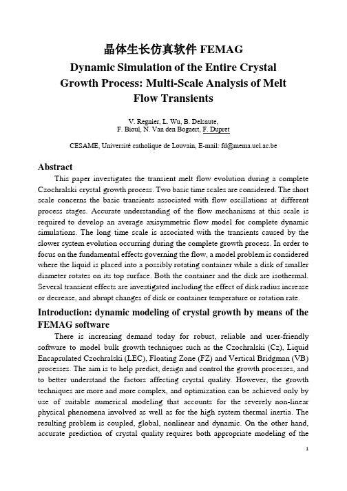
晶体生长仿真软件FEMAGDynamic Simulation of the Entire CrystalGrowth Process: Multi-Scale Analysis of MeltFlow TransientsV. Regnier, L. Wu, B. Delsaute,F. Bioul, N. Van den Bogaert, F. DupretCESAME, Université catholique de Louvain, E-mail: fd@mema.ucl.ac.be AbstractThis paper investigates the transient melt flow evolution during a complete Czochralski crystal growth process. Two basic time scales are considered. The short scale concerns the basic transients associated with flow oscillations at different process stages. Accurate understanding of the flow mechanisms at this scale is required to develop an average axisymmetric flow model for complete dynamic simulations. The long time scale is associated with the transients caused by the slower system evolution occurring during the complete growth process. In order to focus on the fundamental effects governing the flow, a model problem is considered where the liquid is placed into a possibly rotating container while a disk of smaller diameter rotates on its top surface. Both the container and the disk are isothermal. Several transient effects are investigated including the effect of disk radius increase or decrease, and abrupt changes of disk or container temperature or rotation rate.Introduction: dynamic modeling of crystal growth by means of the FEMAG softwareThere is increasing demand today for robust, reliable and user-friendly software to model bulk growth techniques such as the Czochralski (Cz), Liquid Encapsulated Czochralski (LEC), Floating Zone (FZ) and Vertical Bridgman (VB) processes. The aim is to help predict, design and control the growth processes, and to better understand the factors affecting crystal quality. However, the growth techniques are more and more complex, and optimization can be achieved only by use of suitable numerical modeling that accounts for the severely non-linear physical phenomena involved as well as for the high system thermal inertia. The resulting problem is coupled, global, nonlinear and dynamic. On the other hand,accurate prediction of crystal quality requires both appropriate modeling of the governing physics, and highly accurate dynamic numerical methods for computing the evolution of the solid-liquid interface shape and the temperature field gradient in its vicinity.The FEMAG simulation software developed in the CESAME center of the University of Louvain is currently used by major crystal growth companies. The numerical model is both global and dynamic, and takes the effect of melt convection into account. Diffuse surface radiation is considered. Geometrical unknowns are dynamically coupled to the other unknowns, i.e. temperature field, velocity field, electrical potential, etc., leading to a complex non-linear system of equations whose solution is found by use of a decoupled scheme at every time step of the simulation. Whereas in its first generation FEMAG already performed global quasi-steady or time-dependent simulations, applications were restricted to top cone, shouldering and body growth stages.Both laminar and non-laminar flow models were considered, including or not the effect of axisymmetric magnetic fields. The objective of launching the FEMAG-2 software generation has been to provide a fully automatic simulator predicting the entire growth process while handling correctly the switches between the growth stages, together with coupling dynamic calculations with accurate melt flow prediction.A significant difficulty lay in the important evolution of the system geometry during a complete growth process. Indeed, the solidified region is very small during seeding and subsequently becomes larger and larger, while the volume of the molten region decreases continually and can take a complex shape during tail-end stage. The solution adopted combines several approaches based on a representation of the furnace by means of deforming unstructured meshes together with automatic mesh generation. New geometrical methods were designed to allow easy calculation of the different system free surfaces (solidification front, melt/gas interface including crystal/melt and crucible/melt menisci, and crystal/gas surface). These methods allow performing easy time-dependent simulations even for stages of the process where important geometrical changes occur.Another important difficulty to address in FEMAG-2 development was related to the complexity of dynamic melt flow modeling. Several problems must be solved to accurately couple melt flow predictions with crystal growth process simulation. First, in semi-conductor growth, the melt flow is time-dependent, 3D and weakly turbulent, whereas it can exhibit 3D azimuthal andtemporal structured oscillations. The use of an axisymmetric quasi-steady flow model is devoted to average the effect of these oscillations, and the principal issue is to determine reliable average flow models, with the corresponding boundary conditions, above the steady laminar regime. Secondly, due to high nonlinearities, the solution of non-laminar flow problems can be quite difficult while, in most cases, these problems exhibit the numerical stability and convergence issues of transport-dominated systems. To this end, appropriate iterative schemes and stabilization techniques were introduced into the FEMAG-2 flow module. Thirdly, in order to achieve coupling with global thermal calculations, the melt flow problem is solved in FEMAG-2 at several stages of the simulation by using a quasi- steady model, while long term thermal transients are treated by including appropriate source terms into the momentum and energy equations. Interpolation between the collected results provides the flow pattern and the velocity field at each time step of the dynamic simulation.Crystal quality can be predicted from the melt flow and temperature histories as long as the physical models are known. Therefore, solid phase simulators are currently developed in FEMAG-2 to calculate defect formation, diffusion and recombination, dislocation generation and motion, etc., on the basis of heat transfer and flow simulation results. A related objective is to develop off-line control algorithms, the ultimate goal being to provide an easy way to determine the evolution of the different process parameters (heater power, pull rate, crystal and crucible rotation rates, crucible lift, magnetic field design and intensity…) in order to optimize selected process variables characterizing crystal shape and quality. For all these reasons it is of the utmost importance to develop accurate and reliable flow models for bulk crystal growth dynamic simulation. Objectives of the paper in terms of melt flow modelling The present paper is devoted to investigating the evolution of the melt flow regime and pattern during the complete Cz crystal growth process. To this end, two basic time scales must be considered. The short time scale, which is typically of the order of tens of seconds in silicon growth, concerns the basic transients associated with flow oscillations at different stages of the growth process. Accurate understanding of the flow behaviour at this scale is required to develop the average axisymmetric flow model to be used in global dynamic simulations. The long time scale, which is typically of the order of tens of minutes in Cz silicon growth, is associated with the flow and heat transfer transients caused by the long term system evolution. In particular, the melt height is continuallydecreasing during the complete growth process. In addition, the crystal radius changes significantly during cone growth and tail-end stages, while simultaneously the heat transfer is strongly affected by the heater power modifications required to obtain a crystal of the prescribed shape – it should be recalled that heater power is slowly decreased during conical growth in order to let crystal radius increase, while it experiences a quick peak during shouldering in order to stop conical growth, and it is progressively increased during tail-end stage in order to let crystal radius decrease to terminate the growth process.As the aim is here to provide better understanding of the crystal growth melt flow transients at these two time scales, a model problem is considered where the liquid is placed into a possibly rotating cylindrical container while a rotating disk of smaller diameter is placed at the top surface of the liquid. The container and the disk are at uniform, but possibly different, temperatures in order to generate buoyancy forces from radial temperature gradient effect. The advantage of this approach is to allow focusing on the fundamental effects governing the flow by reducing the number of system parameters –the latter being the height of the liquid domain, the container and disk diameters and temperatures, and some material properties of the liquid. Additional parameters can be introduced to characterize the imposed magnetic field if any, but any other effect such as radiation transfer, which is not directly affecting the flow, is removed from the model in order to focus on flow issues only. For validation purpose, this system has been the object of isothermal and non-isothermal experimental investigations by means of a simple apparatus.In order to capture the particular effects related to the flow behaviour at the short time scale (including the detail of its oscillations in a periodic, quasi-periodic or chaotic regime), a particular simulation technique has been developed where the long term effects are frozen while a laminar flow model is used. Very high mesh and time step refinements are required and therefore short time scale simulations, whose understanding represent a first objective of the paper, are limited to rather small periods of time.On the other hand, long time scale simulations can only be performed provided an appropriate axisymmetric average flow model is introduced. This non-laminar model is developed by fitting the simulations to short time scale results. The second objective of the paper is to investigate by use of this non-laminar model the importance of the long term flow transients resulting from process parameter changes, such as increase or decrease of disk radius, abrupt change of temperature or rotation rate of the disk or the container, etc. To this end,several examples will be completely analyzed and presented at the conference. ReferencesF. Dupret, P. Nicodème, Y. Ryckmans, P. Wouters, M.J. Crochet, Int. J. Heat Mass Transfer, 33 (1990), 1849.F. Dupret & N. Van den Bogaert, in Handbook of Crystal Growth, Vol. 2B, Ch. 15, Elsevier, Neth. (1994), 875. R. Assaker, N. Van den Bogaert, F. Dupret, Magnetohydrodynamics, 31 (1995), 254.N. Van den Bogaert & F. Dupret, J. Crystal Growth, 166 (1996), 446; 171 (1997), 65; 171 (1997), 77. R. Assaker, N. Van den Bogaert, F. Dupret, J. Crystal Growth, 180 (1997), 450.F. Dupret, N. Van den Bogaert, R. Assaker, V. Regnier, in Proc. 8th Int. Symp. on Si Mat. Sc. and Tech., 1998ECS meeting, Proc. Vol. 98-1 of the Electrochem. Soc., Pennington, NJ (1998), 396.T. Sinno, E. Dornberger, R.A. Brown, W. von Ammon, F. Dupret, Materials Science and Engineering: R Reports, 28 (2000), 149.。
全球半导体晶体生长仿真著名商业软件FEMAG用户故事(一)莱布尼茨晶体生长研究所(IKZ)

全球半导体晶体生长仿真著名商业软件FEMAG用户故事(一)莱布尼茨晶体生长研究所(IKZ)利用FEMAG软件改进区域熔炼法生长锗单晶的工艺区域熔炼法,又称区域提纯,主要用以提纯金属、半导体。
基本过程是将材料制成细棒,用高频感应加热,使一小段固体熔融成液态。
熔融区慢慢从放置材料的一端向另一端移动。
在熔融区的末端,固体重结晶,而含杂质部分因比纯质的熔点略低,较难凝固,便富集于前端。
与常见的直拉法相比,用区熔法生产锗单晶有如下优点:(1)区熔法本身就有提纯功能,因此,区熔法生产锗单晶的产品的纯度高,质量好。
(2)区熔法生产锗单晶不与石英玻璃等容器接触,因此没有沾污。
区熔法生产锗单晶具有上述优点,因此,很多高质量的电子器件,尤其是要求高的集成电路多采用区熔法生产的锗单晶来制造。
但是与此同时,区熔法也有如下缺点:(1)工艺烦琐,生产成本较高。
(2)很难生产出大直径的锗单晶棒。
为了改进区熔法的生产工艺,生产出大直径的锗单晶棒,坩埚的自由悬浮区需要更加稳定的机械平衡与热平衡。
在此过程中,一个光滑的进给杆以及可调的熔化区对于整个相界面形成是必要的。
莱布尼茨晶体生长研究所(IKZ)利用FEMAG-FZ软件进行了此过程的模拟,如下图所示:计算25毫米晶体的温度场:左图为较小的进给杆;中间为开始优化配置;右图为三相点向下移动1毫米依据数值模拟与实验结果的结合,IKZ在原有的工艺基础上进行改进,调整了进给杆的速度,从而优化了晶体的生长速度,如下为35毫米锗晶体轴向纵切后的结构腐蚀图:莱布尼茨晶体生长研究所(Leibniz Institute for Crystal Growth)(IKZ)致力于研究晶体材料生长的基础研究以及相关的生长过程的加工工艺。
其主要研究内容为:•晶体尺寸从分米到纳米之间的材料生长工艺研究•研究并发展新的加工技术•表征晶体以及开发新的表征晶体方法•组件的设计以及相关加工设备的生产。
利用晶体生长模拟软件FEMAG进行蓝宝石晶体生长模拟的方法专选课件
Sapphire Simulation Objective
➢ The market of Sapphire is experiencing a very fast growth rate and become very competitive ➢Many companies invest in simulation software in order to reinforce their positions ➢ HEM, Czochralski and Kyropoulos process require optimization and a good understanding ➢ Strong need for efficient numerical tools. ➢ Radiation effects in the participating crystal and melt is a complex problem.
▪ A dynamic simulation tool ▪ Complete process simulation ▪ Dynamic effect of interface deformation ▪ Varying processing conditions
CONFIDENTIAL
Sapphire Crystal Growth Simulation
利用晶体生长模拟软件FEMAG进行蓝宝石晶体生长模拟 的方法
Content ➢ General introduction ➢ Sapphire Growth
CONFIDENTIAL
Introduction
For more than 25 years, FEMAGSoft develops simulation software dedicated to the research and development of optimal crystal growth processes. 1984 First research on Germanium growth in University of Louvain.
晶体生长计算软件FEMAG浮区法生长晶体方法
FEMAGSoft © 2011
2. A global simulation tool (cont’d)
Induction Heating in FZ semi-conductor growth
Conduct or
d B
Dissipated power:
Force density:
Alternating magnetic field effects : 1) Heat flux
1. Introduction 2. Global simulation tool
3. Simulation examples
4. Discussion
FEMAGSoft © 2011
2. A global simulation tool
Typical FEMAG-FZ global unstructured mesh for heat transfer and induction heating
FEMAGSoft © 2011
2. A global simulation tool (cont’d)
Prediction of Crystal Defects
FEMAGSoft © 2011
2. A global simulation tool (cont’d)
Quasi-steady simulation of the growth of a 100 mm silicon crystal
Growth of a 100 mm silicon crystal
(1mm/min pull rate) Predicted defect delta -(CI-CV) distribution by means of a quasi-steady simulation
晶体生长软件FEMAG教程之材料赋予
FEMAGCZVersion 2.10Homework 2wxCreGeoDecember 10, 2008FEMAG Soft S.A. LouvainlaNeuve, Belgium Table of Contents1. HOMEWORK GOALS (4)2. ASSOCIATED FILES (4)3. WXCREGEO (4)3.1. Starting wxCreGeo (4)3.2. Import geometry file (5)3.3. Material file (5)3.4. Set material properties (5)3.5. Change the material parameters (8)3.6. Set operating conditions and computational parameters (8)3.7. Ending (10)4. CONTROL ARCHIVE FILE (10)5. SUMMARY (10)5.1. Program features and file results (10)5.2. Procedures: if I want to (11)5.3. Important remark (11)FEMAGCZ 2.10Homework 22Typographic attributes used in this manualSymbols used in this manualContactsupport@FEMAGCZ 2.10Homework 23Homework goals1. Homework goalsAt the end of this homework, you should be able:–to visualize your 2D mesh.–to assign the appropriate material type to the different parts of the puller and hence to set the material properties to each part.–to set the operating process conditions (kinematics, thermal conditions, gas and melt flow, magnetic field).–to set the computational parameters (local and global convergence criteria, time duration of a step (if time dependent problem)).2. Associated filesThis homework is based on the previous homework, the corresponding archive being “ctrl_geotool.tgz”.If required, please extract the “ctrl_geotool.tgz” archive in the “training/” working directory.3. wxCreGeowxCreGeo is the FEMAGCZ module used for mesh visualization and for the input of all material parameters, boundary conditions, operating conditions, and computational parameters.3.1. Starting wxCreGeoStart wxCreGeo by running wxcregeo from your working directory.wxCreGeo is organized in two windows:•the main window organized in four parts: the menu bar, main field, computation log and status line.•the “Plot/Tree View” window (Illustration 1) displaying the geometry and the list of macroelements composing the geometry.Closing the main window terminates the program. Closing secondary (plot and tree view) windows hides them. Using right mouse button in plot and tree view gives access to the pulldown menu commands.FEMAGCZ 2.10Homework 24Illustration 1 Geometry mesh display3.2. Import geometry fileImport the files containing the mesh by means of File>Import project..., choose the “training.ini” file, and press <OK>.In the plot panel of “Plot/Tree View” window (Illustration 1), you can visualize the 2D mesh by pressing <Display/hide mesh>. In the tree list of the same window, you can see the list of the macroelements.3.3. Material fileThe material data are stored in a database. FEMAGCZ uses two databases:–The default database is linked to the wxCreGeo user interfaces, and proposes default material data. The default database is loaded with the wxCreGeo interface opening. This database is stored on your computer system into a material file using the “.mat” filename extension.–The current database is linked to a specific model, and proposes the material data linked to this model. This material database is loaded when the specific model is opened in wxCreGeo. This database is stored in the “.h5” file corresponding to the model.A standard material database, “default.mat” had to be installed with FEMAGCZ.If you have not yet created your own material files, copy the default one “default.mat” provided with FEMAGCZ distribution into another name, e.g. “myFile.mat”. It is better to work with your own material file because, in case of new FEMAGCZ installation, existing “default.mat” could be replace by the default file.3.4. Set material properties1.In the main window, select Option>Materials file..., and choose the materials file you will use(“myFile.mat”).Run Materials>reset to default to update the current material database.2.For each 1D, 2D or melt/crystal macroelement, set its material properties: with the right mousebutton, click on it in the plot panel or in the tree list and select Set Material from the pulldown menu. In the material selection box you have to choose between:•a predefined material from the list. These predefined materials are stored in the materials file.•a “local” noname material associated only with the concerned macroelement. In this case, you have to complete the material setting sheet.We use the following predefined materials:FEMAGCZ 2.10Homework 25Click on it and select your material For example, in order to set material for the melt/crystal macroelement, click on “mc” in the tree list and select Set Material from the tree view pulldown menu. Then, choose “Silicon” from thematerial predefined list (Illustration 2).FEMAGCZ 2.10Homework 263.In order to easily visualize the macroelement material in the plot panel, you can assign a color to each material.Two possible ways:•Materials>Edit current...: to edit the current material database, i.e. changes will only be taken into account for the current model.•Materials>Edit default...: to edit the global material database, i.e. changes will be saved in the materials file and taken into account for all other geometries.In the materials editor, set the material colors (Illustration 3), select File>Save and finally, File>Exit . Come back in wxCreGeo main window, to take changes into account you have to do:•View>Refresh , if you performed changes by Edit current...•Materials>Reset to default followed by View>Refresh , if you performed changes by the other way.To turn filling on/off, select View>Fill 2D(i).FEMAGCZ 2.10Homework 27Click in the field and choose your color3.5. Change the material parameters1.Change the insulator thermal conductivity of the global database:1.Run Materials>Edit default... .The default database (as defined in Options>Material File...) is automatically loaded in the material editor window. Remind you that this database is linked to the wxCreGeo user interfaces. It is loaded with the wxCreGeo interface opening.2.In the “Solid materials” panel, select the “Insulator” item from the material list.3.Change the thermal conductivity from 1 W/mK to 0.15 W/mK.4.select File>Save and File>Exit.Come back in wxCreGeo main window, to take changes into account you have to run Materials>Reset to default followed by View>Refresh.2.Change the molten silicon thermal conductivity only for the current simulation problem:1.Run Materials>Edit current...2.The current database is automatically loaded in the material editor window. Remind you thatthe current is linked to the model you are editing, and proposes the material data linked to this model. This material database is loaded when the specific model is opened in wxCreGeo. This database is stored in the “.h5” file corresponding to the model.3.In the “2Di materials”, select the “Silicon [FEMAGSoft 2005]” item from the material list.4.Change the melt thermal conductivity from 42.9 W/mK to 110 W/mK.5.select File>Save and File>Exit.Come back in wxCreGeo main window, to take changes into account you have to run View>Refresh.In case of simulation without melt convection computation, the effect of the melt flow on the heat transfer can still be modeled by means of an enhanced melt thermal conductivity of the molten silicon, which sums up the contributions of heat convection and diffusion.3.You can check by means of Materials>Edit default... that the molten silicon thermal conductivityin the default database is still 42.9 W/mK. Whereas, the insulator thermal conductivity is set to0.15 W/mK in both databases.3.6. Set operating conditions and computational parameters◆Kinematics•Set the seed velocity to 0.1 mm/min.•Keep gravity to 9.81 m/s2.•Set the crystal rotation rate to 20 RPM.Define the following domains as rotating with the crystal: “training_pull_rod” and “mc”.•Set the crucible rotation rate to 15 RPM.Define the following domains as rotating with the crucible: “cement”, “training_crucible” and “training_support” (use “Select” button to access the selection window).◆Thermal operating conditions•Set a specific adaptive power of 10,000 [W/m3] on the heater macroelement (training_heater).Select the “training_heater” macroelement from the list, imposed a specific power of 10,000 W/m3, select “adaptive” option and click on <Apply>.The actual heater power will be computed in order that the computed temperature of the trijunction point fit with the crystal melting temperature.FEMAGCZ 2.10Homework 28•Specify external boundary conditions (Illustration 4) by pressing on the corresponding button. Keep a temperature of 300 K along the furnace shell except for gas outlet having a flux boundary condition q=100*(T300) W/m 2.•We do not use particular emissivities and additional fluxes.In order to specify particular emissivities and additional fluxes you have to press the corresponding button to open the dialog window. Choose sides alternatively and specify value for T0, h and emissivity. Then, press <OK>.•We do not have to define additional temperature control points.Please remember that the actual heater power will be computed in order that the computed temperature of the control point fit with the imposed temperature. In case of ingot growth, the trijunction point is constrained to be a temperature control point.The number of temperature control point has to be equal to 1 or to the number of adaptive heater power. Hence, in the current case, the number of adaptive heater power being equal to 1, the number of temperature control point must be equal to 1.◆Gas flow mode l •Select the “e01_gas” gas enclosure item.•Tick off “With inlets and outlets” box and specify the inlet sides ID's and the outlet side ID's. Please remember that several inlet/outlet sides can be defined.•Set the furnace pressure to 0.015 bar.•Set the flow rate per inlet side by pressing the corresponding <Edit> button. For the inlet side ID 180, impose a flow rate of 0.030 m 3/s at the specified pressure. Click on <Apply>.•Set the gas flow computational parameters:–The relaxation coefficient allows to relax the effect of the gas flow on the temperature field.The relaxation coefficient can be increased to 0.8 ... 0.9 in case of horizontal temperature profile in cavity. However, by increasing the relaxation coefficient, you increase the iteration number and hence the computational time.Please note that the global solution is not affected by this parameter.Keep default value (0.5).–The convergence criterion can be used to reduce the computational accuracy. This is interesting in case of intermediate computations such as used in stepbystep procedure. In this case, decrease the accuracy for intermediate computation and increase it for the final solution. As the accuracy is reduced, the computational time is reduced, too.Define a value of 1.0e05.•Click on <Apply>.FEMAGCZ 2.10Homework 29Illustration 4: External boundary conditiondialog box.◆Melt flow modelThis panel allows to choose the melt flow model parameters. This panel can be neglected in a first stage.◆Magnetic fieldsWe do not yet use magnetic fields. The data related to magnetic field will be set in a later stage.◆Computational parametersYou have to define the crystal and melt boundary conditions by pressing the corresponding button. Define a temperature condition along crystal wall and melt free surface (except on the sides adjacent to the trijunction point), while keeping default parameter elsewhere. Change the convergence criteria for the global and local iterations to:–Trijunction temperature: 0.1 K.–Interface position: 0.1 mm–Convergence tolerance: 1.000e04.3.7. EndingSave input data as “couplage/data/training.h5” file by doing File>Save.When everything is completed, do File>Export Geometry to generate files needed for the computation. Now, you can exit wxCreGeo and start your FEMAGCZ simulation.Note: When running wxCreGeo in a later stage, you can read the “training.h5” file by doing File>Open (useful to make modifications).4. Control archive fileMake the “ctrl_wxcregeo.tgz” control archive file of your working directory (Linux command: tar cvzf ctrl_wxcregeo.tgz ./*) and send it to support@.5. Summary5.1. Program features and file resultswxcregeo program:–Main actions: to assign material properties to the different parts of the puller and to define the operating conditions and the computational parameters.–Input:–material data (“./couplage/exe/default.mat”)–operating conditions (kinematics, thermal conditions, gas and melt flow, magnetic field)–computational parameters (local and global convergence criterions, time duration of a step (if time dependent problem))–Output files:–“./couplage/data/GID.h5” (produced by File>Save): file produced to be opened by wxCregeo in order to make modifications to the project.FEMAGCZ 2.10Homework 210Summary5.2. Procedures: if I want to ...If I want to change the insulator thermal conductivity of the global database:1.Run Materials>Edit default... .2.The default database (as defined in Options>Material File...) is automatically loaded in thematerial editor window. Remind you that this database is linked to the wxCreGeo user interfaces. It is loaded with the wxCreGeo interface opening.3.In the “Solid materials” panel, select the “Insulator” item from the material list.4.Change the thermal conductivity from 1 W/mK to 0.15 W/mK.5.select File>Save and File>Exit.Come back in wxCreGeo main window, to take changes into account you have to run Materials>Reset to default followed by View>Refresh.If I want to change the molten silicon thermal conductivity only for the current simulation problem:1.Run Materials>Edit current...2.The current database is automatically loaded in the material editor window. Remind you that thecurrent is linked to the model you are editing, and proposes the material data linked to this model.This material database is loaded when the specific model is opened in wxCreGeo. This database is stored in the “.h5” file corresponding to the model.3.In the “2Di materials”, select the “Silicon” item from the material list.4.Change the melt thermal conductivity from 42.9 W/mK to 110 W/mK.5.select File>Save and File>Exit.Come back in wxCreGeo main window, to take changes into account you have to run View>Refresh.5.3. Important remarkWhen inverse simulations are considered, namely when the heater power required to growth a prescribed ingot shape is looked for, the number of adaptive power has to be at least equal to the number of control points. In case of ingot growth, the trijunction point is constrained to be a temperature control point. Therefore, at least one macroelement has to be defined has adaptive in that case.FEMAGCZ 2.10Homework 211。
- 1、下载文档前请自行甄别文档内容的完整性,平台不提供额外的编辑、内容补充、找答案等附加服务。
- 2、"仅部分预览"的文档,不可在线预览部分如存在完整性等问题,可反馈申请退款(可完整预览的文档不适用该条件!)。
- 3、如文档侵犯您的权益,请联系客服反馈,我们会尽快为您处理(人工客服工作时间:9:00-18:30)。
FEMAG晶体生长建模软件
F
产品与服务
FEMAG Soft擅长所有类型晶体材料生长方面的工艺模拟专业技术,比如:
• 直拉法(Czochralski)
• 区熔法(Floating Zone)
• 适用于铸锭定向凝固过程工艺(DS),Bridgman法
• 物理气相传输法(PVT)
产品模块
1. FEMAG/CZ-Czochralski (CZ) Process
适用于Czochralski直拉法生长工艺和Kyropoulos生长工艺
2. FEMAG/DS-Directional Solidification (DS) Process
适用于铸锭定向凝固过程工艺
3. FEMAG/FZ-Float Zone Process (FZ)
适用于区熔法生长工艺
FEMAG软件是由比利时鲁汶大学研
发的晶体生长数值仿真软件。20世纪80
年代中期,鲁汶大学François Dupret教
授带领其团队,开始晶体生长的研究,经
过10多年的行业研发及应用,François
Dupret教授于2003年成立了FEMAG
S.A.(总部设在比利时Louvain-la-Neuve
市),正式推出晶体生长数值仿真软件
FEMAG。如今,FEMAG软件已成为全球
行业用户高度认可的数值仿真工具,在晶
体生长数值模拟领域处于国际领先地位。
主要功能
1. 全局热传递分析
“全局性”即包涵所有拉晶要素在内,并考虑传热模式的耦合。全局热传
递模拟分析,主要考虑:炉内的辐射和传导、熔体对流和炉内气体流量分析。
2. 热应力分析
按照经验,一般情况下,晶体位错的产生与晶体生长过程中热应力的变化
有着密切的关系。该软件可以进行三维的非轴对称和非各向同性温度场热应力
分析计算,可以提出对晶体总的剪切力预估。
“位错”的产生是由于在晶体生长过程中,热剪应力超越临界水平,被称为
CRSS(临界分剪应力),而导致的塑性变形。
3. 点缺陷预报
该软件可以预知在晶体生长过程中的点缺陷(自裂缝和空缺),该仿真可以很
好的预测在晶体生长过程中点缺陷的分布。
4. 动态仿真
动态仿真提供了对复杂几何形状对于时间演变的预测。该预测把发生在晶
体生长和冷却过程中所有瞬时的影响因素都考虑在内。为了准确地预报晶体点
缺陷和氧分,布动态仿真尤其是不可或缺的。
5. 固液界面跟踪
在拉晶的过程中准确预测固液界面同样是一个关键问题。对于不同的柑祸
旋转速度和不同的提拉高度,其固液界面是不同的。
6. 加热器功率预测
利用软件动态仿真反算加热功率对于生长合格晶体也是非常必要的。
7. 绘制温度梯度
通过仿真,固液交界面的温度梯度可以很方便的计算出来。这一结果对于理
论缺陷的预报是非常有用的。
技术特色
1. 全局建模(Global modeling)——将熔炉分为宏观单元(macro
elements),包含液体与固体成分、散热机箱、cement接合单元
2. 时间相关建模(Time dependent modeling)——使用与时间相关的仿
真模型,比如准稳态、准动态、Cz生长逆向或直接动态模型
3. FEM离散化——使用2D、Spectral 3D、Cartesian 3D等模型
4. 几何建模——可以准确处理变形体、界面以及所有的边界层
5. 求解技术——高效线性求解+Newton & Raphson迭代
模拟软件的优点
• 晶体生长模拟软件能够提供晶体生长炉内部环境及晶体生长过程,从
而为生产商提供必要的信息,以便分析晶体生长过程特征及其工艺优缺点是否
符合市场需求。通过模拟软件提供的功能,生产商可以提高工艺改进、优化时
的目标与优先次序。
• 模拟软件所提供的虚拟实验使晶体生长商在物理实现之前设计、校验
他们的生产工艺。虚拟实验不但操作方便、经济实惠、而且基本上不存在任何
技术限制。
应用范围
FEMAG Soft公司的模拟软件应用于开发、优化以下类型的晶体生长工艺:
• IC级单晶硅和光伏级晶体硅
• Ⅲ-Ⅴ族化合物半导体晶体材料,如GaAs/GaP等
• 锗单晶
• 蓝宝石、氧化物和卤化物
• 碳化硅
应用领域
10多年来,FEMAG Soft公司所开发的软件产品获得了国际上诸多专业生
产企业的青睐,在以下类型的企业中得到广泛应用:
• 集成电路用单晶硅生产企业
• 光伏技术用单晶硅生产企业
• LED光电技术用氧化物晶体生产企业
• 蓝宝石晶体生产企业