易去污AATCC 130
美国防火测试NFPA130标准详细介绍
美国防火测试NFPA130标准详细介绍现在高铁、动车交通四通八达,但是高铁的安全与成功依托于严格的标准,其中防火性能涉及哪些标准呢?下面一起来看看美国防火测试。
标准名称--NFPA 130:2014美国轨道车辆材料防火测试标准NFPA 130:2014 Standard for fixed guideway transit and passenger rail systems NFPA 130:2014 有轨列车及铁路客运体系标准标准适用范围--轨道车辆材料防火测试标准NFPA 130:2014NFPA 130标准包括所有的地铁、轨道交通工具、铁路系统的防火要求。
NFPA 130标准制定的目的就是建立统一的有轨列车及铁路客运体系的最低防火及其危险的要求。
NFPA 130:2014主要测试标准:ASTM E162 产品表面火焰传播的测试方法ASTM E662 烟密度的测试方法ASTM E648 地面材料临界热辐射量测试BSS 7239 毒性的测试BSS 7238 烟密度的测试方法UL 1685 电线电缆防火测试ASTM D 3675 柔性多孔材料的表面燃烧测试方法ASTM C 1166 柔性火焰蔓延的试验方法Bombardier SMP 800-C 毒性测试与分析NFPA 130:2014测试项目及标准1、车辆一般内部组件/材料NFPA 130测试项目及标准ASTM E 162 表面燃烧测试ASTM E 662 烟密度测试BSS 7239 毒性测试2、地面材料NFPA 130测试项目及标准ASTM E 648 临界热辐射量测试ASTM E 662 烟密度测试BSS 7239 毒性测试3、座垫、床垫NFPA 130测试项目及标准ASTM D 3675柔性材料表面燃烧ASTM E 662 烟密度测试BSS 7239 毒性测试4、隔热、隔音保温材料NFPA 130测试项目及标准ASTM E 162 表面燃烧测试ASTM E 662 烟密度测试BSS 7239 毒性测试5、弹性体NFPA 130测试项目及标准(门窗密封条、垫圈)ASTM C 1166 弹性体材料火焰延伸测试ASTM E 662 烟密度测试BSS 7239 毒性测试NFPA 130轨道车辆材料如下橡胶产品、密封条天花板、吊顶、吊顶覆盖物墙体、墙体覆盖物纺织品、无纺布、窗帘、遮阳产品座椅、座椅装饰地板(PVC、橡胶、铝蜂窝板等)地面材料发泡材料(海绵、三聚氰胺泡沫)粉末涂料、胶粘剂、颜料、光油玻璃钢复合材料、SMC片材防火胶水门、窗及门窗框架扶手、拉手、头枕、可折叠护套、小开关等小部件连接器、连接设备加热管、冷却管、波纹管、空调管其它机车材料。
PTS-130和PTS-130F的组合高压DC试验设备说明书

® Advanced Test Equipment Rentals
(800) 404-ATEC
PTS Series - DC High Voltage Test Set and Megohmmeter
0 - 130 kV DC hipot and Megohmmeter
PTS-130
PTS-130F
0 - 130 kV DC, 10 mA
Model
Input
Output Duty Voltmeter Current Meter
Megohmmeter Size & Weight (W x D x H) Output Termination
Scope of Supply
The PTS-130 and PTS-130F are combination high voltage DC proof tester and megohmmeter. Dielectric strength and insulation resistance testing are combined into one instrument saving time, money, size and weight. Equipped with a 5-range current meter scaled 0 - 1 dc microamps for accurate current measurement down to a 10 nanoamp resolution in the x1 range. Using the alternate scale on the current meter allows the PTS Series to double as a Megohmmeter up to 13 teraohms, scaled 100-1 megohms, insulation resistance can be taken at any voltage. An accurate 2 range voltmeter rounds out the standard instrumentation. Additional features include ruggedized anti-static and transit protected meters, rugged two piece design with foam padded handles, full-wave bridge rectifier, internal shorting solenoid with discharge resistors, and is CE marked. For other voltage options, please see the rest of our PTS Series which range from 15kV to 600kV DC. See our DBT Series for bench-top options.
AATCC135纺织物经全自动家庭洗涤后的尺寸变化中文版
纺织品经家庭洗涤后尺寸变化的试验方法1、目的与范围1.1、本试验方法是为了测试纺织品经过家庭洗涤程序后的尺寸变化。
目前,消费者使用的洗衣机一般包括以下可选择的程序:四个洗涤温度;三个搅拌速度;两个漂洗温度;以及四个干燥程序。
2、原理2.1、洗涤前,在织物上做好几组的基准线标记,然后按照一般的家庭洗涤方法进行洗涤,最后测量织物试样的尺寸变化。
3、术语3.1、尺寸变化:在特定的条件下,织物试样在长度或宽度方向上的改变。
尺寸变化,通常用试样的这部分的变化与原尺寸相比的百分率来表示。
3.2、伸长:尺寸的变化导致试样在长度或宽度方向的增加。
3.3、洗涤:它是指利用液体清洁剂溶液进行处理(清洗),旨在清除污垢或污迹的过程,通常包括漂洗、脱水和干燥的过程。
3.4、收缩:尺寸的变化导致试样在长度或宽度方向的减少。
4、安全预防注:这些安全保护措施仅供参考。
它是对试验程序的补充,并非包括所有的措施。
采用本标准中安全和正确的处理方法是用户的责任。
有关材料的安全数据表,制造厂商的其他建议等详细的资料,必须向制造厂商咨询。
也必须参考和遵守美国劳工部职业安全与健康署的所有标准和规定。
4.1、要切实遵守实验室操作规范。
在实验室内的任何区域,必须戴好防护眼镜。
4.2、1993 AATCC标准洗涤剂WOB会引发炎症。
应该小心使用,以防止接触眼睛和皮肤。
4.3、在使用实验室试验装置时,应遵守制造厂商的安全建议。
5、仪器与原料5.1、自动洗衣机(见12.1)5.2、自动翻滚式烘干机(见12.2)。
5.3、调湿/干燥样品架:可拉式筛板或带孔的晾衣架(见12.3)。
5.4、滴干和悬挂晾干装置。
5.5、1993AATCC标准洗涤剂(见12.10,12.11)。
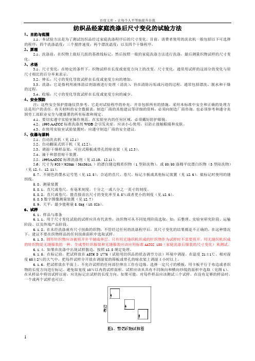
5.6、尺寸为920×920mm(36x36in.)的漂白缝边棉质织物(1型陪洗物),或50/50涤棉平纹漂白织物(3型陪洗物)(见12.4、12.11)。
5.7、不褪色的墨水记号笔(见12.5),合适的直尺、卷尺、标记卡板或其他标记装置(见12.6)。
BA-130W水性环氧面漆产品说明书
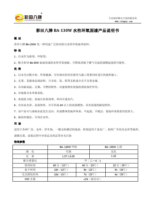
彩田八牌BA-130W水性环氧面漆产品说明书概述彩田八牌BA-130W是一种用途广泛的双组分水性环氧地坪涂料。
特性1、以水作为溶剂,环保型;2、配合彩田BA-30W底油而成的水性环氧地板,可降低因地下潮气引起的漆膜起泡的可能性。
优势1、以水为分散介质,环保健康,可在相对封闭及使用与施工需要同时进行的场所施工。
2、无毒、是属食品级涂料,只含硅、氧、铝等无机成分且不含重金属。
3、具有耐高温、无烟、不燃的特性。
对建筑物有很强的消防保护作用。
4、对地基含水率要求低。
5、表面张力低、表面污垢易清理、单向可透水汽。
6、具有高光泽、高装饰性,并可形成4H以上的表面硬度,具有很强的耐划伤性。
7、该产品可与基础水泥发生反应,形成整体的地坪体系,不起泡、不脱层,使地坪系统使用更持久。
8、耐侯性极佳,可用在室外。
用途适用于各种厂房、仓库、停车场、一楼无防潮层的地面,特别适用于食品厂、制药厂车间及仓库等场所,漆膜无毒,涂装过程中对食品及药品等亦无污染物理参数性能指标施工说明混合:甲乙组按比例混合(4:1)充分搅拌,乳化3-5分钟后,加混合后总量12%的水(即甲组份的15%)搅拌后均匀辊涂或刮涂在地面上。
检验标准:用透明杯取少量搅拌后的混合物,如杯底有油珠则表示未乳化完成,需继续搅拌;若无油珠,则表示乳化完成施工方法:1、底涂层:彩田BA-30W水性环氧底油,参考用量为0.2kg/㎡,具体应根据现场基面情况而定,达到均匀成膜为准;2、中涂层:视基面的平整度和强度,用彩田BA-30W水性环氧底油调配石英砂或石英粉施工到所需厚度;3、面涂层:甲、乙组混合均匀后辊涂、刷涂或喷涂。
参考用量:0.30㎏/㎡左右(两遍)漆膜面层厚度:约80 um(一遍干膜厚度)工具清洗:水。
施工条件:建议在10℃以上使用本品。
为避免水汽凝结,要求施工基面干燥洁净,基面含水率小于4%,空气相对湿度小于85%。
在狭窄空间内施工和干燥期间,应保持良好的通风。
FR-TPX T130塑料材料物性表

FR-TPX是由三井化學(Mitsui Chemicals)所開發出的一種玻璃纖維強化型工程塑膠。
TPX為4-甲基戊烯(4-methylpentene)(由丙烯二聚化而得)的共聚合體,是一種結晶性聚烯烴。
目前,三井化學為世界上唯一的TPX製造/銷售商。
而FR-TPX係將玻璃纖維以化學鍵結接於TPX 基材,因此,玻璃纖維與基材樹脂間有絕佳的黏著性。
FR-TPX可提供優異的電氣性質,耐熱性,耐焊接性以及薄壁成型性,因此,最適合應用於各種不同的工業零件,尤其是在電氣與電子工業領域。
FR-TPX特性一、電氣性質TPX分子中無極性基,FR-TPX具有優異的高頻特性與電氣絕緣性質,其介電常數很低(2.5),介電消散因子也很低(0.0007),更具特色者為其高頻範圍的介電損失很低。
此外,FR-TPX具有優異的電氣絕緣性質。
FR-TPX的吸濕率非常低,所以其電氣性質即使在高濕度的環境下仍然可維持不變。
圖1顯示頻率對介電常數的影響。
結果顯示FR-TPX的介電常數較PPS與FR-PBT低得多。
圖2顯示頻率對介電消散因子的影響。
由圖可看出FR-TPX的介電消散因子要較PPS與FR-PB 低得多。
圖3顯示溫度對介電常數的影響。
很明顯的,FR-TPX的介電常數除了較PPS與FR-PBT為低之外,受溫度的影響亦小。
二、耐熱性與耐焊接性FR-TPX的熔點高(230℃),且熱變形溫度高(190℃),因此具有優異的耐熱性與耐焊接性。
由FR-TPX所製成的零件在高溫下,甚至於暴露於在熔點之上的溫度下數分鐘,仍然可以維持良好的形狀。
FR-TPX的耐焊接性大致介於FR-PBT與PPS之間。
(1)耐焊接性FR-TPX具有優異的耐焊接性,較FR-PBT為高。
FR-TPX在高溫下,甚至於暴露於在熔點(230℃)之上的溫度下數分鐘,仍然可以維持良好的形狀。
圖5顯示FR-TPX在高溫下的形狀維持性。
很明顯的可看出FR-TPX在高溫下的形狀維持性優於FR-PBT。
AATCC 30 耐真菌活性,纺织品材料的评定:纺织品材料耐霉菌防腐烂
Developed in 1946 by AATCC Commit-tee RA31; revised 1952, 1957, 1971, 1981, 1987, 1988 (with title change), 1993, 1999; reaffirmed 1970, 1974, 1979, 1989, 1998; editorially revised and reaffirmed 1986, 2004.1. General Purpose and Scope1.1 The two purposes of this test method are to determine the susceptibil-ity of textile materials to mildew and rot and to evaluate the efficacy of fungicides on textile materials.2. Principle2.1 Tests I, II, III and IV can be used, singly or in combination, depending on the type of exposure to which the textile material will be subjected. For example, if the final product will come in contact with soil, Test I, which simulates this ex-posure, should be used; if the finished product will never come in contact with soil or tropical conditions, a much less severe test (e.g., II or III) should be used. Test II is specifically designed for cellu-lose-containing materials while Test III is for all others. For all materials intended for outdoor and above ground use, Test IV should be used. The two important considerations when evaluating textile materials in relation to fungal growth are (1) the actual deterioration of the textile product (rot), and (2) growth not neces-sarily deteriorating the product but mak-ing it unsightly (mildewy) often with an unpleasant and musty odor.2.2 Certain pre-exposures of textile products may be indicated when specific end-uses are critical (see Appendix A). When the end-use will be near high tem-perature and the fungicide may be vola-tile, a preliminary oven exposure may be desired. When the end-use will be in tropical exposures or outside with rainfall present, a leaching exposure should be performed before mildew evaluation is made. When at all possible, the textile material should be exposed to the ex-pected conditions of use prior to perform-ing this test.3. Terminology3.1 mildew resistance, n.—in textiles, resistance to development of unsightly fungal growths and accompanying un-pleasant, musty odors on textile materials exposed to conditions favoring such growths.3.2 rot resistance, n.—in textiles, re-sistance to deterioration of a textile mate-rial as a result of fungal growth in or on it.NOTE: Such deterioration is normallyassessed by measuring loss in tensilestrength.4. Safety PrecautionsNOTE: These safety precautions arefor information purposes only. The pre-cautions are ancillary to the testing proce-dures and are not intended to be all inclu-sive. It is the user’s responsibility to usesafe and proper techniques in handlingmaterials in this test method. Manufac-turers MUST be consulted for specificdetails such as material safety data sheetsand other manufacturer’s recommenda-tions. All OSHA standards and rulesmust also be consulted and followed.4.1 This test should be performed onlyby trained personnel. The U.S. Depart-ment of Health and Human Services pub-lication Biosafety in Microbiological andBiomedical Laboratories should be con-sulted (see 24.1).4.2 CAUTION: Some of the fungi usedin these tests are allergenic and patho-genic; i.e., capable of infecting humansand producing disease. Therefore, everynecessary and reasonable precautionmust be taken to eliminate this risk to thelaboratory personnel and to personnel inthe associated environment. Wear protec-tive clothing, respiratory protection, andimpervious gloves when working withthe organisms. NOTE: Choose respira-tory protection that prevents penetrationby the spores.4.3 Good laboratory practices shouldbe followed. Wear safety glasses in alllaboratory areas.4.4 All chemicals should be handledwith care.4.5 An eyewash/safety shower shouldbe located nearby for emergency use.4.6 Sterilize all contaminated samplesand test materials prior to disposal.4.7 Exposure to chemicals used in thisprocedure must be controlled at or belowlevels set by government authorities (e.g.,Occupational Safety and Health Admin-istration’s [OSHA] permissible exposurelimits [PEL] as found in 29 CFR 1910-1000 of January 1, 1989). In addition, theAmerican Conference of GovernmentalIndustrial Hygienists (ACGIH) Thresh-old Limit Values (TLVs) comprised oftime weighted averages (TLV-TWA),short term exposure limits (TLV-STEL)and ceiling limits (TLV-C) are recom-mended as a general guide for air con-taminant exposure which should be met(see 24.2).Test ISoil Burial5. Scope5.1 This procedure is generally consid-ered to be the most severe test for textileproducts. Only those specimens that willcome in direct contact with soil—such assandbags, tarpaulins, tents—need to betested by this procedure. It can also beused for testing experimental textilefungicides.6. Test Specimens6.1 Prepare the fabric specimens withdimensions 15.0 ± 1.0 × 4.0 ± 0.5 cm (6.0± 0.4 × 1.5 ± 0.2 in.) with the long dimen-sion parallel to the warp and unravelingto 2.5 ± 0.1 cm width (1.0 ± 0.04 in.), or,in the case of fabric with less than 20threads per 2.5 cm (1.0 in.) to a predeter-mined number of threads to give a speci-men 2.5 ± 1.0 cm in width (1.0 ± 0.4 in.).A sample cutter can also be used (see24.3). The number of specimens will varyaccording to the number of variables. Thesuggested number of specimens is fivefor each treatment, control and referencefabric.7. Test Procedure7.1 Viability control: Expose untreatedcotton cloth 271 g/m2 (8 oz/yd2) in thesoil bed for seven days during the test pe-riod to verify fungal activity. The soil bedshall be considered as satisfactory if theviability control fabric loses 90% break-ing strength after seven days exposure.7.2 Soil Bed: Place the air-dry test soil(see 24.4) in trays, boxes or suitable con-tainers to a depth of 13.0 ± 1.0 cm (5.1 ±0.4 in.) and bring to optimum moisturecontent by gradual addition of water ac-companied by mixing to avoid puddling.After allowing it to stand for 24 h, sieve itthrough a 6.4 mm (0.25 in.) mesh screen.Maintain uniform moisture content bycovering the soil container with a suitablelid. The moisture content of the soil dur-ing the test period shall be maintained be-tween 25 ± 5% (based on dry weight). Ifthe surrounding air is maintained athigher than 83 ± 3% relative humidity,AATCC Test Method 30-2004Antifungal Activity, Assessment on Textile Materials:Mildew and Rot Resistance of Textile Materialsthe loss of moisture is negligible.7.3 Incubation: Bury the specimens horizontally on 10.0 ± 1.0 cm (3.9 ±0.4in.) of soil, spaced at least 2.5 cm (1.0 in.) apart and then cover with 2.5 ±0.5 cm (1.0 ± 0.2 in.) of test soil. Incuba-tion periods can vary from 2-16 weeks,depending on severity of service require-ments, and other factors of importance to the interested parties. Maintain the tem-perature at 28 ± 1°C (82 ± 2°F) during the test period.8. Evaluation and Report8.1 Strength loss determination: Re-move specimens, gently wash with water,dry at room temperature for 22 ± 4 h and then condition in an atmosphere of 64 ±2% humidity and a temperature of 24 ±3°C (76 ± 6°F) for 24 h. Determine break-ing strength by the method outlined in ASTM D 5035, Standard Test Method for Breaking Force and Elongation of Textile Fabrics (Strip Force), using 25 × 75 mm (1× 3 in.) jaw faces. The gage length is de-termined as 25% of the specimen length.Testing can be performed every two weeks or as specified by the end-user.8.2 Report: Report the length of expo-sure to the soil bed, percent retained breaking strength when compared to the unexposed textile, any pre-exposure of specimens before burying and percent re-tained breaking strength of untreated specimen and/or viability control.Test IIAgar Plate, Chaetomium Globosum 9. Scope9.1 This procedure is used for evaluat-ing rot resistance of cellulose-containing textile materials that will not come in contact with soil. It may also be used for determining uniformity of fungicide treatment.10. Test Specimens10.1Proceed as in Section 6, if strength loss is to be determined. If only a visual examination is performed, a mini-mum of five samples is required. How-ever, any number can be tested depending on end-users request. Cut 3.8 ± 0.5 cm (1.5 ± 0.2 in.) diameter discs from both treated and untreated samples.11. Test Procedure11.1 Organism: Chaetomium globo-sum . American Type Culture Collection No. 6205 (see 24.5).11.2 Culture medium (see 24.6): The mineral salts agar should have the follow-ing composition:Ammonium nitrate, NH 4NO 3........3.0 g Potassium dihydrogen phosphate,KH 2PO 4.....................................2.5 gDipotassium hydrogen phosphate,K 2HPO 4....................................2.0 g Magnesium sulfate,MgSO 4 · 7H 2O..........................0.2 g Ferrous sulfate,FeSO 4 · 7H 2O...........................0.1 g Agar............................................20.0 g Distilled water....................to 1000 mL 11.3 Inoculum: Place agar solution in any desired container such as test tube,French square bottle, Erlenmeyer flask, or petri dish. Sterilize in an autoclave at 103kPa (15 psi) and 121°C (250°F) for 15min and cool in a position which affords maximum inoculation surface. After the agar has hardened, under aseptic condi-tions, place on its surface a disc of filter paper previously sterilized by dry heat in an oven at 71 ± 3°C (160 ± 5°F) for 1 h.Streak the filter paper with spores of Cha-etomium globosum by use of a sterile nee-dle. Incubate at 28 ± 1°C (82 ± 2°F) for approximately 10-14 days to produce abundant growth. Remove the filter paper from the container and add it to 50 ± 2mL of sterile distilled water containing a few glass beads and shake vigorously to bring the spores into suspension. Use this suspension for inoculum in 11.5.11.4 Culture chamber: Melt mineral salts agar of the composition specified in 11.2 in an autoclave and distribute into any convenient container. Sterilize under conditions given in 11.3 and leave undis-turbed until the agar hardens.11.5 Inoculation: Pre-wet the speci-mens (but do not rub or squeeze) in water containing 0.05% of a nonionic wetting agent (see 24.7) and place in contact with the hardened agar medium in each con-tainer under aseptic conditions. Distribute 1.0 ± 0.1 mL of the inoculum evenly over the 15.0 ± 1.0 × 4.0 ± 0.5 cm (6.0 ± 0.4 ×1.5 ± 0.2 in.) specimens by means of a sterile pipette. Use 0.2 ± 0.01 mL of inoc-ulum for the 3.8 ± 0.5 cm (1.5 ± 0.2 in.)discs. Set up a control specimen, cellu-lose filter paper or untreated control, in a similar way by using 1.0 ± 0.1 or 0.2 ±0.01 mL of sterile water.12. Evaluation and Report12.1 Strength loss evaluation: Proceed as per 8.1 and report the change in break-ing strength as compared to the sample before exposure or the control if available.12.2 Visual assessment: Report the ex-tent of fungal growth on the discs, using a microscope (50X) where necessary, in accordance with the following scheme:Observed GrowthNo growthMicroscopic growth (visible only un-der the microscope)Macroscopic growth (visible to the eye)Test IIIAgar Plate, Aspergillus Niger 13. Score13.1 Certain fungi, of which Aspergil-lus niger is one, can grow on textile prod-ucts without causing measurable break-ing strength loss within a laboratory experimental time frame. Nonetheless,their growth may produce undesirable and unsightly effects. This procedure is used to evaluate textile specimens where growth of these fungi is important.14. Test Specimens14.1 Cut duplicate 3.8 ± 0.5 cm (1.5 ±0.2 in.) diameter discs from both treated and untreated samples. Other shapes and sizes can be used provided any antici-pated size of the growth-free zone is taken into consideration.15. Test Procedure15.1 Organism: Aspergillus niger ,American Type Culture Collection No.6275 (see 24.5).15.2 Culture medium: Proceed as per 11.2. Other suitable media are Czapek (Dox) Agar and Sabouraud Dextrose Agar (see 24.8).15.3 Inoculum: Add scrapings from a ripe (7-14 days) fruiting culture of As-pergillus niger grown on the medium de-scribed in 11.2 containing 3.0 ± 0.1% glu-cose, to a sterile Erlenmeyer flask containing 50 ± 1 mL of sterile water and a few glass beads. Shake the flask thor-oughly to bring the spores into suspen-sion. Use this suspension as the inoculum.15.4 Inoculation: If the test medium contains glucose, distribute evenly 1.0 ±0.1 mL of the inoculum over the surface of the agar. Pre-wet the discs (but do not rub or squeeze) in water containing 0.05% of a nonionic wetting agent (see 24.7) and place on the agar surface. Dis-tribute evenly over each disc 0.2 ± 0.01mL of the inoculum by means of a sterile pipette. If the test medium does not con-tain glucose, a negative control fabric is required to ensure inoculum viability. In-cubate all specimens at a temperature of 28 ± 1°C (82 ± 2°F) for 14 days when mineral salts agar is used and for seven days when 3% glucose is added to the mineral salts agar.16. Evaluation and Report16.1 At the end of the incubation pe-riod, report the percentage of surface area of the discs covered with the growth of Aspergillus niger , using a microscope (50X) where necessary, in accordance with the following scheme:Observed GrowthNo growth (if present, report the size of the growth-free zone in mm) Microscopic growth (visible only un-der the microscope)Macroscopic growth (visible to the eye)Test IVHumidity Jar, Mixed Spore Suspension 17. Scope17.1 This test method is designed to determine the fungistatic effectiveness of treatments intended to control mildew and non-pathogenic fungal growth on ar-ticles or surfaces composed of textile ma-terials intended for outdoor and above ground use and which are usually water-proofed.17.2 For this test method visual assess-ment is used. Additionally, breaking strength may be determined by method as per 8.1.18. Principle18.1 Treated and untreated, nutrient-saturated strips of fabric are sprayed with a mixed spore suspension of mildew-causing organisms and incubated at 90 ±2% relative humidity. Mildew growth on treated and untreated strips is rated at weekly intervals for up to four weeks.19. Apparatus19.1 Glassware: 500 mL French square jars or equivalent with fitting screw caps. Caps are modified by center drilling and inserting an appropriate size stainless steel or brass bolt to which a hook (formed from a 6.5 ± 0.5 cm length [2.6 ±0.2 in.] of #22 nickel-chromium wire or other non-corrosive wire) is attached. 19.2 Plastic paper clips or nylon thread to suspend the specimens from the screw caps of the French jars.19.3 Atomizer, DeVilbiss #152 (or equivalent) operated at 69 kPa (10 psi).19.4 Counting chamber suitable for de-termining spore concentrations; e.g., hemocytometer.20. Test Specimens20.1 The specimens are prepared by cut-ting 2.5 ± 0.5 cm × 7.5 ± 0.5 cm (1.0 ± 0.2× 3.0 ± 0.2 in.) strips from sample weigh-ing 170.0 ± 34.0 g/m2 (5.0 ± 1.0 oz/yd2). For heavier fabrics use strips 2.0 ± 0.5 cm × 2.0 ± 0.5 cm (0.8 ± 0.2 × 0.8 ± 0.2 in.).20.2 Use at least four specimens of each treated and untreated fabric.20.3 Untreated fabric strips, identical in all other respects to the treated speci-mens under test, are required to establish the test validity. If untreated fabrics are not available, use a control cloth with thefollowing requirements:Cotton:American type, good mid-dlingWarp:18.5 tex z 886 × 2S748Weft:30 tex z 630 × 2S748Weave:Plain 34 ends/cm and 17picks/cmMass/unitarea:230.0 g/m2 (6.8 oz/yd2)Finish:Scoured only21. Test Procedures21.1 Organisms:21.1.1 Aspergillus niger, AmericanType Culture Collection No. 6275.21.1.2 Penicillium varians, AmericanType Culture Collection No. 10509.21.1.3 Trichoderma viride, AmericanType Culture Collection No. 28020 (see24.5).21.2 Culture medium:21.2.1 Maintain stock culture of eachof test tube slants of potato dextrose agarfor A. niger and P. varians, and malt ex-tract agar for T. viride (see 24.6 and 24.8for media).21.2.2 Incubate new stock culture 7-10days at 25 ± 1°C (77 ± 2°F), then store at2-10°C (36-50°F).21.3 Preparation of conidial suspen-sions:21.3.1 Conidial suspensions of fungalorganisms are prepared by adding 10 mLof a sterile 0.5% saline solution contain-ing 0.05% of a non-fungicidal wettingagent (see 24.7) to a 7-10 day agar cul-ture.21.3.2 Scrape the surface of the culturegently with a platinum or nichrome wireto liberate the spores. Agitate the liquidslightly to disperse the spores without de-taching mycelial fragments, and gentlydecant the mold suspension into a flaskcontaining a few glass beads.21.3.3 Shake the dispersion vigorouslyto break up any clumps of spores andthen filter through a thin layer of sterilecotton or glass wool. Conidial suspen-sions may be stored at 6 ± 4°C (43 ± 7°F)for up to four weeks.21.3.4 Inoculum for test should be ad-justed using a hemocytometer or aPetroff-Hausser bacteria counter to con-tain five million conidia per mL on day ofuse by appropriate dilution of stock sus-pension with saline solution.21.4 Preparation of test specimens:21.4.1 To ensure luxuriant growth,both the test and control strips must besaturated with a sterilized glycerol nutri-ent solution of the following composi-tion: 97.6% distilled water, 2.0% glyc-erol, 0.1% K2HPO4, 0.1% NH4NO3,0.05% MgSO4·7H2O, 0.1% yeast extractand 0.05% of a nonionic wetting agent(see 24.7). Adjust the pH to 6.3 ± 0.1.Sufficient nutrient solution should be pre-pared to saturate all the specimens usedin a single test.21.4.2 Soak each strip in nutrient forthree minutes or until saturated. Squeezeexcess liquid and allow fabric strips to airdry before proceeding with application oftest fungi.21.5 Pre-mix equal volumes of wellagitated conidial suspensions of A. niger,T. viride and P. varians. Evenly distrib-ute 1.0 ± 0.1 mL of the above suspensiononto both sides of each specimen eitherby spraying or by means of a pipette.21.6 Suspend fabric strips using plasticpaper clips or nylon thread from the capsof individual jars containing 90 ± 3 mL ofwater each. Hook position must be ad-justed so that the bottom ends of attachedstrips are all at a uniform height abovethe water level. The caps are tightened,then backed off one-eighth turn to allowfor some ventilation.21.7 Incubate at 28 ± 1°C (82 ± 2°F)for 14 days (for non-coated cellulosictextiles) or 28 days (for non-cellulosic orcoated cellulosic textiles).22. Evaluation and Report22.1 A record of the percent of surfacearea covered with fungal growth for eachstrip is made at weekly intervals, or untilheavy growth occurs on each sample rep-licate. Using a microscope (50X) wherenecessary, assess each specimen in accor-dance with the scheme given in 12.2.22.2 After seven days each controlstrip must show macroscopic growth. Ifthis is not the case repeat the test sincetest conditions were not valid.22.3 Any adverse effect of incubationon the fabric; e.g., color changes, flexibil-ity, water repellency, should be qualita-tively reported.22.4 Strength loss determination canbe carried out as per 8.1.22.5 The results of this test methodhave to be correlated to claims and direc-tions for use recommended for the mil-dew control product plus any other crite-ria agreed upon by the interested parties.23. Precision and Bias23.1 The precision and bias of this testmethod are being established. If thebreaking strength loss is determined, thenrefer to the statement given in ASTM D5035.24. Notes24.1 Publication available from U.S. De-partment of Health & Human Services—CDC/NIH-HHS Publication No. (CDC) 84-8395.24.2 Booklet available from PublicationsOffice, ACGIH, Kemper Woods Center, 1330Kemper Meadow Dr., Cincinnati OH 45240;tel: 513/742-2020.24.3 A JDC Precision sample cutter may bepurchased from Thwing-Albert Instrument Co., 10960 Dutton Road, Philadelphia PA 19154; tel: 215/637-0100; fax: 215/632-8370; Cat. #99 Model JOC25.24.4 Types of soil which have been found satisfactory for this purpose include garden and naturally fertile topsoils, composts and non-sterile greenhouse potting soils. An equal blend of good topsoil, well rotted and shred-ded manure, and coarse sand should be used. These usually possess the proper physical characteristics, along with an organic content sufficient to ensure a high degree of microbial activity and the presence of cellulose destroy-ing organisms. The optimum moisture content of these is about 30% moisture above oven dry weight.24.5 Chaetomium globosum ATCC 6205, Aspergillus niger, ATCC 6275, Penicillium varians, ATCC 10509 and Trichoderma vir-ide, ATCC 28020, can be purchased from the American Type Culture Collection, P.O. Box 1549, Manassas V A 20108; tel: 703/365-2700; fax: 703/365-2701.24.6 Culture medium having composition prescribed in 11.2 (Mineral Salts) can be pur-chased from Baltimore Biological Laborato-ries, 250 Schilling Cir., Cockeysville MD 21030.24.7 Triton™ X-100 (Rohm & Haas Co., Philadelphia PA 19104) has been found to be a good wetting agent. Suitable alternatives aredioctyl sodium sulfosuccinate or N-methyl-tauride derivatives.24.8 These culture media can be bought ei-ther from Baltimore Biological Laboratories(see 24.6) or Difco Laboratories, 920 HenrySt., Detroit MI 48201.24.9 ASTM D 5035 can be used for yarn,thread, cordage or tape (see 12.1).24.10If testing is being performed for Fed-eral Standards, use AATCC 30-2. Other or-ganisms can be used: Myrothecium verrucariaATCC 9095, QM 460; Trichoderma SP ATCC9645, QM 365; Memnoniella echinata ATCC11973, QM 1225; Aspergillus niger ATCC6275, QM 458; Aspergillus claratus ATCC18214, QM 862.Appendix APre-TreatmentsA1. LeachingA1.1 The leaching should conform inprinciple to the following procedure:Water from a faucet is passed through atubing into leaching vessels, care beingtaken that specimens having differentamounts of the same treatment are in sep-arate vessels. Flow is adjusted to ensure acomplete change of water not less thanthree times in 24 h. The delivery tubesare inserted down through the center ofwire mesh cylinders in the leaching ves-sels and held in the wire cylinders withrubber bands and leached for 24 h. ThepH and temperature of the water is re-corded and included in the report of thetest results.A2. VolatilizationA2.1 Standard specimens of the fabricto be tested are exposed continuously todry heat at 100-105°C (212-221°F) for24h in a well ventilated oven.A3. WeatheringA3.1 Portions of the material to betested are exposed on a series of weather-ing racks at 45° to the horizontal facingSouth, between April 1 and October 1, insuch a manner as to avoid sagging orflapping. It is recommended that suchracks be set up in at least four locationswithin the United States; e.g., Washing-ton DC; Miami FL; New Orleans LA;and suitable desert locations.。
纺织品的多功能自清洁整理_王建庆
件下一般需要24 h,在日光照射下则需10 d左右,因 而 这 类 产 品 更 多 地 适 用 于 户 外 场 合 ,如 外 墙 涂 料 、幕 墙玻璃等[1 - 5]。通 过 仿 生 学 改 变 纺 织 品 的 表 面 结 构,使之形成 微 乳 状 突 出 表 面 的“荷 叶 结 构 ”,从 而 赋予纺织品以优异 的 拒 水 效 果,是 制 造 具 有 自 清 洁 效能纺织品的有效途径。该方法采用超细纤维制成 超高密度拒水透气 的 纺 织 品,或 者 用 硅 溶 胶 类 材 料 及某些金属盐在纺织品表面通过自组装方式形成纳 米 级 沉 积 物 ,使 之 具 有 微 乳 状 的 表 面 月
文 章 编 号 :0253 -9721 ( 2011 ) 06 -0095 -05
纺织学报 Journal of Textile Research
Vol. 32,No. 6 Jun. ,2011
纺织品的多功能自清洁整理
王建庆1 ,李 戎2
(1. 东华大学 教育部生态纺织重点实验室,上海 201620; 2. 东华大学 国家染整工程技术研究中心,上海 201620)
(1. Key Laboratory of Science & Technology of Eco-Textile,Ministry of Education,Donghua University, Shanghai 201620,China; 2. National Engineering Technology Research Center for dyeing and Finishing of Textiles,Donghua University,Shanghai 201620,China)
1. 2 试验仪器和设备
NACE MR0175-2002
Sulfide Stress Cracking--NACE MR0175-2002, MR0175/ISO 15156650The DetailsNACE MR0175, “Sulfide Stress Corrosion Cracking Resistant Metallic Materials for Oil Field Equipment” is widely used throughout the world. In late 2003, it became NACE MR0175/ISO 15156, “Petroleum and Natural Gas Industries - Materials for Use in H 2S-Containing Environments in Oil and Gas Production.” These standards specify the proper materials, heat treat conditions and strength levels required to provide good service life in sour gas and oil environments.NACE International (formerly the National Association ofCorrosion Engineers) is a worldwide technical organization which studies various aspects of corrosion and the damage that may result in refineries, chemical plants, water systems and other types of industrial equipment. MR0175 was first issued in 1975, but the origin of the document dates to 1959 when a group of engineers in Western Canada pooled their experience in successful handling of sour gas. The group organized as a NACE committee and in 1963 issued specification 1B163, “Recommendations of Materials for Sour Service.” In 1965, NACE organized a nationwide committee, which issued 1F166 in 1966 and MR0175 in 1975. Revisions were issued on an annual basis as new materials and processes were added. Revisions had to receive unanimous approval from the responsible NACE committee.In the mid-1990’s, the European Federation of Corrosion (EFC) issued 2 reports closely related to MR0175; Publication 16,“Guidelines on Materials Requirements for Carbon and Low Alloy Steels for H 2S-Containing Environments in Oil and Gas Production” and Publication 17, “Corrosion Resistant Alloys for Oil and Gas Production: Guidance on General Requirements and Test Methods for H 2S Service.” EFC is located in London, England.The International Organization for Standardization (ISO) is aworldwide federation of national standards bodies from more than 140 countries. One organization from each country acts as the representative for all organizations in that country. The American National Standards Institute (ANSI) is the USA representative in ISO. Technical Committee 67, “Materials, Equipment andOffshore Structures for Petroleum, Petrochemical and Natural Gas Industries,” requested that NACE blend the different sour service documents into a single global standard.This task was completed in late 2003 and the document was issued as ISO standard, NACE MR0175/ISO 15156. It is now maintained by ISO/TC 67, Work Group 7, a 12-member “Maintenance Panel” and a 40-member Oversight Committeeunder combined NACE/ISO control. The three committees are an international group of users, manufacturers and service providers. Membership is approved by NACE and ISO based on technical knowledge and experience. Terms are limited. Previously, some members on the NACE Task Group had served for over 25 years.NACE MR0175/ISO 15156 is published in 3 volumes.Part 1: General Principles for Selection of Cracking-Resistant Materials Part 2: Cracking-Resistant Carbon and Low Alloy Steels, and the Use of Cast IronsPart 3: Cracking-Resistant CRA’s (Corrosion-Resistant Alloys) and Other AlloysNACE MR0175/ISO 15156 applies only to petroleum production, drilling, gathering and flow line equipment and field processing facilities to be used in H 2S bearing hydrocarbon service. In the past, MR0175 only addressed sulfide stress cracking (SSC). In NACE MR0175/ISO 15156, however, but both SSC and chloride stress corrosion cracking (SCC) are considered. While clearly intended to be used only for oil field equipment, industry hasapplied MR0175 in to many other areas including refineries, LNG plants, pipelines and natural gas systems. The judicious use of the document in these applications is constructive and can help prevent SSC failures wherever H 2S is present. Saltwater wells and saltwater handling facilities are not covered by NACE MR0175/ISO 15156. These are covered by NACE Standard RP0475,“Selection of Metallic Materials to Be Used in All Phases of Water Handling for Injection into Oil-Bearing Formations.”When new restrictions are placed on materials in NACE MR0175/ISO 15156 or when materials are deleted from this standard, materials in use at that time are in compliance. This includes materials listed in MR0175-2002, but not listed in NACEMR0175/ISO 15156. However, if this equipment is moved to a different location and exposed to different conditions, the materials must be listed in the current revision. Alternatively, successful use of materials outside the limitations of NACE MR0175/ISO 15156 may be perpetuated by qualification testing per the standard. The user may replace materials in kind for existing wells or for new wells within a given field if the environmental conditions of the field have not changed.Sulfide Stress Cracking--NACE MR0175-2002, MR0175/ISO 15156651New Sulfide Stress Cracking Standard for RefineriesDon Bush, Principal Engineer - Materials, at Emerson Process Management Fisher Valves, is a member and former chair of a NACE task group that has written a document for refinery applications, NACE MR0103. The title is “Materials Resistant to Sulfide Stress Cracking in Corrosive Petroleum RefiningEnvironments.” The requirements of this standard are very similar to the pre-2003 MR0175 for many materials. When applying this standard, there are changes to certain key materials compared with NACE MR0175-2002.ResponsibilityIt has always been the responsibility of the end user to determine the operating conditions and to specify when NACE MR0175applies. This is now emphasized more strongly than ever in NACE MR0175/ISO 15156. The manufacturer is responsible for meeting the metallurgical requirements of NACE MR0175/ISO 15156. It is the end user’s responsibility to ensure that a material will be satisfactory in the intended environment. Some of the operating conditions which must be considered include pressure, temperature, corrosiveness, fluid properties, etc. When bolting components are selected, the pressure rating of flanges could be affected. It is always the responsibility of the equipment user to convey the environmental conditions to the equipment supplier, particularly if the equipment will be used in sour service.The various sections of NACE MR0175/ISO 15156 cover the commonly available forms of materials and alloy systems. The requirements for heat treatment, hardness levels, conditions of mechanical work and post-weld heat treatment are addressed for each form of material. Fabrication techniques, bolting, platings and coatings are also addressed.Applicability of NACE MR0175/ISO 15156Low concentrations of H 2S (<0.05 psi (0,3 kPa) H 2S partialpressure) and low pressures (<65 psia or 450 kPa) are considered outside the scope of NACE MR0175/ISO 15156. The low stress levels at low pressures or the inhibitive effects of oil may give satisfactory performance with standard commercial equipment. Many users, however, have elected to take a conservative approach and specify compliance to either NACE MR0175 or NACE MR0175/ISO 15156 any time a measurable amount of H 2S is present. The decision to follow these specifications must be made by the user based on economic impact, the safety aspects should a failure occur and past field experience. Legislation can impact the decision as well. Such jurisdictions include; the Texas Railroad Commission and the U.S. Minerals Management Service (offshore). The Alberta, Canada Energy Conservation Board recommends use of the specifications.Basics of Sulfide Stress Cracking (SSC) and Stress Corrosion Cracking (SCC)SSC and SCC are cracking processes that develop in the presence of water, corrosion and surface tensile stress. It is a progressive type of failure that produces cracking at stress levels that are well below the material’s tensile strength. The break or fracture appears brittle, with no localized yielding, plastic deformation or elongation. Rather than a single crack, a network of fine, feathery, branched cracks will form (see Figure 1). Pitting is frequently seen, and will serve as a stress concentrator to initiate cracking.With SSC, hydrogen ions are a product of the corrosion process (Figure 2). These ions pick up electrons from the base material producing hydrogen atoms. At that point, two hydrogen atoms may combine to form a hydrogen molecule. Most molecules will eventually collect, form hydrogen bubbles and float awayharmlessly. However, some percentage of the hydrogen atoms will diffuse into the base metal and embrittle the crystalline structure. When a certain critical concentration of hydrogen is reached and combined with a tensile stress exceeding a threshold level, SSC will occur. H 2S does not actively participate in the SSC reaction; however, sulfides act to promote the entry of the hydrogen atoms into the base material.As little as 0.05 psi (0,3 kPa) H 2S partial pressure in 65 psia (450 kPa) hydrocarbon gas can cause SSC of carbon and low alloy steels. Sulfide stress cracking is most severe at ambient temperature, particularly in the range of 20° to 120°F (-6° to49°C). Below 20°F (-6°C) the diffusion rate of the hydrogen isFigure 1. Photomicrograph Showing Stress Corrosion CrackingSulfide Stress Cracking--NACE MR0175-2002, MR0175/ISO 15156652so slow that the critical concentration is never reached. Above 120°F (49°C), the diffusion rate is so fast that the hydrogen atoms pass through the material in such a rapid manner that the critical concentration is not reached.Chloride SCC is widely encountered and has been extensively studied. Much is still unknown, however, about its mechanism. One theory says that hydrogen, generated by the corrosion process, diffuses into the base metal in the atomic form and embrittles the lattice structure. A second, more widely accepted theory proposes an electrochemical mechanism. Stainless steels are covered with a protective, chromium oxide film. The chloride ions rupture the film at weak spots, resulting in anodic (bare) and cathodic (film covered) sites. The galvanic cell produces accelerated attack at the anodic sites, which when combined with tensile stresses produces cracking. A minimum ion concentration is required to produce SCC. As the concentration increases, the environment becomes more severe, reducing the time to failure. Temperature also is a factor in SCC. In general, the likelihood of SCC increases with increasing temperature. A minimum threshold temperature exists for most systems, below which SCC is rare. Across industry, the generally accepted minimum temperature for chloride SCC of the 300 SST’s is about 160°F (71°C). NACE MR0175/ISO 15156 has set a very conservative limit of 140°F (60°C) due to the synergistic effects of the chlorides, H 2S and low pH values. As the temperature increases above these values, the time to failure will typically decrease.Resistance to chloride SCC increases with higher alloy materials. This is reflected in the environmental limits set by NACEMR0175/ISO 15156. Environmental limits progressively increase from 400 Series SST and ferritic SST to 300 Series, highly alloy austenitic SST, duplex SST, nickel and cobalt base alloys.Carbon SteelCarbon and low-alloy steels have acceptable resistance to SSC and SCC however; their application is often limited by their low resistance to general corrosion. The processing of carbon and low alloy steels must be carefully controlled for good resistance to SSC and SCC. The hardness must be less than 22 HRC. If welding or significant cold working is done, stress relief is required. Although the base metal hardness of a carbon or alloy steel is less than 22 HRC, areas of the heat affected zone (HAZ) will be harder. PWHT will eliminate these excessively hard areas.ASME SA216 Grades WCB and WCC and SAME SA105 are the most commonly used body materials. It is Fisher’s policy to stress relieve all welded carbon steels that are supplied to NACE MR0175/ISO 15156.All carbon steel castings sold to NACE MR0175/ISO 15156 requirements are produced using one of the following processes:1. In particular product lines where a large percentage of carbon steel assemblies are sold as NACE MR0175/ISO 15156 compliant, castings are ordered from the foundry with a requirement that the castings be either normalized or stress relieved following all weld repairs, major or minor. Any weld repairs performed, either major or minor, are subsequently stress relieved.2. In product lines where only a small percentage of carbon steel products are ordered NACE MR0175/ISO 15156 compliant, stock castings are stress relieved whether they are weld repaired by Emerson Process Management or not. This eliminates the chance of a minor foundry weld repair going undetected and not being stress relieved.ASME SA352 grades LCB and LCC have the same composition as WCB and WCC, respectively. They are heat treated differently and impact tested at -50°F (-46°C) to ensure good toughness in low temperature service. LCB and LCC are used in locations where temperatures commonly drop below the -20°F (-29°C) permitted for WCB and WCC. LCB and LCC castings are processed in the same manner as WCB and WCC when required to meet NACE MR0175/ISO 15156.For carbon and low-alloy steels NACE MR0175/ISO 15156imposes some changes in the requirements for the weld procedure qualification report (PQR). All new PQR’s will meet these requirements; however, it will take several years for Emerson Process Management and our suppliers to complete this work. At this time, we will require user approval to use HRC.S -2H++S -2S -2Figure 2. Schematic Showing the Generation of Hydrogen Producing SSCSulfide Stress Cracking--NACE MR0175-2002, MR0175/ISO 15156653Carbon and Low-Alloy Steel Welding hardness Requirements• HV-10, HV-5 or Rockwell 15N.• HRC testing is acceptable if the design stresses are less than 67% of the minimum specified yield strength and the PQR includes PWHT.• Other methods require user approval. • 250 HV or 70.6 HR15N maximum. • 22 HRC maximum if approved by user.Low-Alloy Steel Welding hardness Requirements• All of the above apply with the additional requirement of stress relieve at 1150°F (621°C) minimum after welding.All new PQR’s at Emerson Process Management and our foundries will require hardness testing with HV-10, HV-5 or Rockwell 15N and HRC. The acceptable maximum hardness values will be 250 HV or 70.6 HR15N and 22 HRC. Hardness traverse locations are specified in NACE MR0175/ISO 15156 part 2 as a function of thickness and weld configuration. The number and locations of production hardness tests are still outside the scope of the standard. The maximum allowable nickel content for carbon and low-alloy steels and their weld deposits is 1%.Low alloy steels like WC6, WC9, and C5 are acceptable to NACE MR0175/ISO 15156 to a maximum hardness of 22 HRC. These castings must all be stress relieved to FMS 20B52.The compositions of C12, C12a, F9 and F91 materials do not fall within the definition of “low alloy steel” in NACE MR0175/ISO 15156, therefore, these materials are not acceptable.A few customers have specified a maximum carbon equivalent (CE) for carbon steel. The primary driver for this requirement is to improve the SSC resistance in the as-welded condition. Fisher’s practice of stress relieving all carbon steel negates this need. Decreasing the CE reduces the hardenability of the steel and presumably improves resistance to sulfide stress cracking (SSC). Because reducing the CE decreases the strength of the steel, there is a limit to how far the CE can be reduced.Cast IronGray, austenitic and white cast irons cannot be used for anypressure-retaining parts, due to low ductility. Ferritic ductile iron to ASTM A395 is acceptable when permitted by ANSI, API or other industry standards.Stainless Steel400 Series Stainless SteelUNS 410 (410 SST), CA15 (cast 410), 420 (420 SST) and several other martensitic grades must be double tempered to a maximum hardness of 22 HRC. PWHT is also required. An environmental limit now applies to the martensitic grades; 1.5 psi (10 kPa) H 2S partial pressure and pH greater than or equal to 3.5, 416 (416 SST) is similar to 410 (410) with the exception of a sulfur addition to produce free machining characteristics. Use of 416 and other free machining steels is not permitted by NACE MR0175/ISO 15156.CA6NM is a modified version of the cast 410 stainless steel. NACE MR0175/ISO 15156 allows its use, but specifies the exact heat treatment required. Generally, the carbon content must be restricted to 0.03% maximum to meet the 23 HRCmaximum hardness. PWHT is required for CA6NM. The same environmental limit applies; 1.5 psi (10 kPa) H 2S partial pressure and pH greater than or equal to 3.5.300 Series Stainless SteelSeveral changes have been made with the requirements of the austenitic (300 Series) stainless steels. Individual alloys are no longer listed. All alloys with the following elemental ranges are acceptable: C 0.08% maximum, Cr 16% minimum, Ni 8% minimum, P 0.045% maximum, S 0.04% maximum, Mn 2.0% maximum, and Si 2.0% maximum. Other alloying elements are permitted. The other requirements remain; solution heat treated condition, 22 HRC maximum and free of cold work designed to improve mechanical properties. The cast and wrought equivalents of 302, 304 (CF8), S30403 (CF3), 310 (CK20), 316 (CF8M), S31603 (CF3M), 317 (CG8M), S31703 (CG3M), 321, 347 (CF8C) and N08020 (CN7M) are all acceptable per NACE MR0175/ISO 15156.Environmental restrictions now apply to the 300 Series SST. The limits are 15 psia (100 kPa) H 2S partial pressure, a maximum temperature of 140°F (60°C), and no elemental sulfur. If the chloride content is less than 50 mg/L (50 ppm), the H 2S partial pressure must be less than 50 psia (350 kPa) but there is no temperature limit.There is less of a restriction on 300 Series SST in oil and gas processing and injection facilities. If the chloride content in aqueous solutions is low (typically less than 50 mg/L or 50 ppm chloride) in operations after separation, there are no limits for austenitic stainless steels, highly alloyed austenitic stainless steels, duplex stainless steels, or nickel-based alloys.Sulfide Stress Cracking--NACE MR0175-2002, MR0175/ISO 15156654Post-weld heat treatment of the 300 Series SST is not required. Although the corrosion resistance may be affected by poorlycontrolled welding, this can be minimized by using the low carbon filler material grades, low heat input levels and low interpass temperatures. We impose all these controls as standard practice. NACE MR0175/ISO 15156 now requires the use of “L” grade consumables with 0.03% carbon maximum.S20910S20910 (Nitronic ® 50) is acceptable in both the annealed and high strength conditions with environmental restrictions; H 2S partial pressure limit of 15 psia (100 kPa), a maximum temperature of 150°F (66°C), and no elemental sulfur. This would apply to components such as bolting, plugs, cages, seat rings and other internal parts. Strain hardened (cold-worked) S20910 is acceptable for shafts, stems, and pins without any environmental restrictions. Because of the environmental restrictions and poor availability on the high strength condition, use of S20910 will eventually be discontinued except for shafts, stems and pins where unrestricted application is acceptable for these components.CK3MCuNThe cast equivalent of S31254 (Avesta 254SMO ®), CK3MCuN (UNS J93254), is included in this category. The same elemental limits apply. It is acceptable in the cast, solution heat-treatedcondition at a hardness level of 100 HRB maximum in the absence of elemental sulfur.S17400The use of S17400 (17-4PH) is now prohibited for pressure-retaining components including bolting, shafts and stems. Prior to 2003, S17400 was listed as an acceptable material in the general section (Section 3) of NACE MR0175. Starting with the 2003 revision, however, it is no longer listed in the general section. Its use is restricted to internal, non-pressure containing components in valves, pressure regulators and level controllers. This includes cages and other trim parts. 17-4 bolting will no longer be supplied in any NACE MR0175/ISO 15156 construction. The 17-4 and 15-5 must be heat-treated to the H1150 DBL condition or the H1150M condition. The maximum hardness of 33 HRC is the same for both conditions.CB7Cu-1 and CB7Cu-2 (cast 17-4PH and 15-5 respectively) in the H1150 DBL condition are also acceptable for internal valve and regulator components. The maximum hardness is 30 HRC or 310 HB for both alloys.Duplex Stainless SteelWrought and cast duplex SST alloys with 35-65% ferrite are acceptable based on the composition of the alloy, but there areenvironmental restrictions. There is no differentiation between cast and wrought, therefore, cast CD3MN is now acceptable. There are two categories of duplex SST. The “standard” alloys with a 30≤PREN≤40 and ≥1.5% Mo, and the “super” duplex alloys with PREN>40. The PREN is calculated from the composition of the material. The chromium, molybdenum, tungsten and nitrogen contents are used in the calculation. NACE MR0175/ISO 15156 uses this number for several classes of materials.PREN = Cr% + 3.3(Mo% + 0.5W%) + 16N%The “standard” duplex SST grades have environmental limits of450°F (232°C) maximum and H 2S partial pressure of 1.5 psia (10 kPa) maximum. The acceptable alloys include S31803, CD3MN, S32550 and CD7MCuN (Ferralium ® 255). The alloys must be in the solution heat-treated and quenched condition. There are no hardness restrictions in NACE MR0175/ISO 15156, however, 28 HRC remains as the limit in the refinery document MR0103.The “super” duplex SST with PREN>40 have environmental limits of 450°F (232°C) maximum and H 2S partial pressure of 3 psia (20 kPa) maximum. The acceptable “super” duplex SST’s include S32760 and CD3MWCuN (Zeron ® 100).The cast duplex SST Z 6CNDU20.08M to the French National Standard NF A 320-55 is no longer acceptable for NACE MR0175/ISO 15156 applications. The composition fails to meet the requirements set for either the duplex SST or the austenitic SST.highly Alloyed Austenitic Stainless SteelsThere are two categories of highly alloyed austenitic SST’s that are acceptable in the solution heat-treated condition. There are different compositional and environmental requirements for the two categories. The first category includes alloys S31254 (Avesta 254SMO ®) andN08904 (904L); Ni% + 2Mo%>30 and Mo=2% minimum.Sulfide Stress Cracking--NACE MR0175-2002, MR0175/ISO 15156655Monel ® K500 and Inconel ® X750N05500 and N07750 are now prohibited for use in pressure- retaining components including bolting, shafts and stems. They can still be used for internal parts such as cages, other trimparts and torque tubes. There are no environmental restrictions, however, for either alloy. They must be in the solution heat-treated condition with a maximum hardness of 35 HRC. N07750 is still acceptable for springs to 50 HRC maximum.Cobalt-Base AlloysAlloy 6 castings and hardfacing are still acceptable. There are no environmental limits with respect to partial pressures of H 2S or elemental sulfur. All other cobalt-chromium-tungsten, nickel-chromium-boron (Colmonoy) and tungsten-carbide castings are also acceptable without restrictions.The second category of highly alloyed austenitic stainless steels are those having a PREN >40. This includes S31654 (Avesta 654SMO ®), N08926 (Inco 25-6Mo), N08367 (AL-6XN), S31266 (UR B66) and S34565. The environmental restrictions for thesealloys are as follows:Nonferrous AlloysNickel-Base AlloysNickel base alloys have very good resistance to cracking in sour, chloride containing environments. There are 2 different categories of nickel base alloys in NACE MR0175/ISO 15156:• Solid-solution nickel-based alloys • Precipitation hardenable alloysThe solid solution alloys are the Hastelloy ® C, Inconel ® 625 and Incoloy ® 825 type alloys. Both the wrought and cast alloys are acceptable in the solution heat-treated condition with no hardness limits or environmental restrictions. The chemical composition of these alloys is as follows:• 19.0% Cr minimum, 29.5% Ni minimum, and 2.5% Mominimum. Includes N06625, CW6MC, N08825, CU5MCuC.• 14.5% Cr minimum, 52% Ni minimum, and 12% Mo minimum. Includes N10276, N06022, CW2M.N08020 and CN7M (alloy 20 Cb3) are not included in this category. They must follow the restrictions placed on the austenitic SST’s like 304, 316 and 317.Although originally excluded from NACE MR0175/ISO 15156, N04400 (Monel ® 400) in the wrought and cast forms are now included in this category.The precipitation hardenable alloys are Incoloy ® 925, Inconel ® 718 and X750 type alloys. They are listed in the specification as individual alloys. Each has specific hardness and environmental restrictions.N07718 is acceptable in the solution heat-treated and precipitation hardened condition to 40 HRC maximum. N09925 is acceptable in the cold-worked condition to 35 HRC maximum, solution-annealed and aged to 38 HRC maximum and cold-worked and aged to 40 HRC maximum.The restrictions are as follows:Cast N07718 is acceptable in the solution heat-treated and precipitation hardened condition to 35 HRC maximum. The restrictions are as follows:Sulfide Stress Cracking--NACE MR0175-2002, MR0175/ISO 15156656All cobalt based, nickel based and tungsten-carbide weld overlays are acceptable without environmental restrictions. This includes CoCr-A, NiCr-A (Colmonoy ® 4), NiCr-C (Colmonoy ® 6) and Haynes Ultimet ® hardfacing.Wrought UNS R31233 (Haynes Ultimet ®) is acceptable in the solution heat-treated condition to 22 HRC maximum, however, all production barstock exceeds this hardness limit. Therefore, Ultimet ® barstock cannot be used for NACE MR0175/ISO 15156 applications. Cast Ultimet is not listed in NACE MR0175/ISO 15156.R30003 (Elgiloy ®) springs are acceptable to 60 HRC in the cold worked and aged condition. There are no environmental restrictions.Aluminum and Copper AlloysPer NACE MR0175/ISO 15156, environmental limits have not been established for aluminum base and copper alloys. This means that they could be used in sour applications per therequirements of NACE MR0175/ISO 15156, however, they should not be used because severe corrosion attack will likely occur. They are seldom used in direct contact with H 2S.TitaniumEnvironmental limits have not been established for the wrought titanium grades. Fisher ® has no experience in using titanium in sour applications. The only common industrial alloy is wrought R50400 (grade 2). Cast titanium is not included in NACE MR0175/ISO 15156.zirconiumZirconium is not listed in NACE MR0175/ISO 15156.SpringsSprings in compliance with NACE represent a difficult problem. To function properly, springs must have very high strength(hardness) levels. Normal steel and stainless steel springs would be very susceptible to SSC and fail to meet NACE MR0175/ISO 15156. In general, relatively soft, low strength materials must be used. Of course, these materials produce poor springs. The two exceptions allowed are the cobalt based alloys, such as R30003 (Elgiloy ®), which may be cold worked and hardened to a maximum hardness of 60 HRC and alloy N07750 (alloy X750) which is permitted to 50 HRC. There are no environmental restrictions for these alloys.CoatingsCoatings, platings and overlays may be used provided the basemetal is in a condition which is acceptable per NACE MR0175/ISO 15156. The coatings may not be used to protect a base material which is susceptible to SSC. Coatings commonly used in sour service are chromium plating, electroless nickel (ENC) and nitriding. Overlays and castings commonly used include CoCr-A (Stellite ® or alloy 6), R30006 (alloy 6B), NiCr-A and NiCr-C (Colmonoy ® 4 and 6) nickel-chromium-boron alloys. Tungsten carbide alloys are acceptable in the cast, cemented or thermally sprayed conditions. Ceramic coatings such as plasma sprayedchromium oxide are also acceptable. As is true with all materials in NACE MR0175/ISO 15156, the general corrosion resistance in the intended application must always be considered.NACE MR0175/ISO 15156 permits the uses of weld overlay cladding to protect an unacceptable base material from cracking. Fisher does not recommend this practice, however, as hydrogen could diffuse through the cladding and produce cracking of a susceptible basemetal such as carbon or low alloy steel.Stress RelievingMany people have the misunderstanding that stress relieving following machining is required by NACE MR0175/ISO 15156. Provided good machining practices are followed using sharptools and proper lubrication, the amount of cold work produced is negligible. SSC and SCC resistance will not be affected. NACE MR0175/ISO 15156 actually permits the cold rolling of threads, provided the component will meet the heat treat conditions and hardness requirements specified for the given parent material. Cold deformation processes such as burnishing are also acceptable.BoltingBolting materials must meet the requirements of NACE MR0175/ISO 15156 when directly exposed to the process environment (“exposed” applications). Standard ASTM A193 and ASME SA193 grade B7 bolts or ASTM A194 and ASME SA194 grade 2H nuts can and should be used provided they are outside of the process environment (“non-exposed” applications). If the bolting will be deprived atmospheric contact by burial, insulation or flange protectors and the customer specifies that the bolting will be “exposed”, then grades of bolting such as B7 and 2H are unacceptable. The most commonly used fasteners listed for “exposed” applications are grade B7M bolts (99 HRB maximum) and grade 2HM nuts (22 HRC maximum). If 300 Series SST fasteners are needed, the bolting grades B8A Class 1A and B8MA Class 1A are acceptable. The corresponding nut grades are 8A and 8MA.。
Outokumpu duplex datasheet
Austenitic-ferritic stainless steel also referred to as duplex stainless steels, combine many of the beneficial properties of ferritic and austenitic steels. Due to the high content of chromium and nitrogen, and often also molybdenum, these steels offer good resistance to localised and uniform corrosion. The duplex microstructure contributes to the high strength and high resistance to stress corrosion cracking. Duplex steels have good weldability. Outokumpu produces a whole range of duplex grades from the lean alloyed LDX 2101 up to the super duplex grades 2507 and 4501. This publication presents the properties of LDX 2101 , 2304, LDX 2404™, 2205 and 2507. The properties of 4501 is in general terms very similar to those of 2507. Grade 4501 is delivered if specified.
AATCC 中文完整版
干洗色牢度(AATCC 132)1.仪器及材料1.1 水洗色牢度实验机1.2不锈钢洗杯:直径为75mm,高为125mm,容量为500ml。
1.3 不锈钢珠1.4 未染色斜纹棉布:克重为270+70g/m2,未经整理过的,切割成尺寸为120mm x120mm的布片1.5 全氯乙烯,干洗级1.6 AATCC变色灰卡,AATCC沾色灰卡1.7 分光光度计1.8 摩擦附布1.9 洗涤剂,Perk-Sheen2.测试样品2.1 如果被测试物为织物,每种样布取3块样品,每块样品尺寸为10x5cm。
长边方向平行于经向或纬向。
2.2 如果被测试物为纱线,将其织成尺寸为10x 5cm的织片,长边方向平行于经向或纬向。
2.3 样品准备3.测试程序3.1 将两块未染色的正方形棉斜纹布沿三边缝合,制成一个内尺寸为100mm x100mm的布袋,将一块试样和12片不锈钢圆片放入袋中,用任何方便的形式缝住袋口。
3.2 把装有试样和钢片的布袋放在容器内,在30C+2加入200ml全氯乙烯,如用其它溶剂,需在报告中说明。
在规定的装置中,30C+2C处理试样30min。
3.3 从溶剂中拿出布袋,取出试样,夹于吸水袋或布之间,挤压或离心去除多余的溶剂,将试样悬挂在温度为60+5的热空气中烘干。
3.4 用灰卡评定试样的变色3.5 实验结束后,用滤纸过滤留在容器中的溶剂。
将过滤后的溶剂和空白溶剂到入置于白卡前的比色管,采用透射光,用评定沾色用灰卡比较两者的染色。
汗渍色牢度(AATCC15)1.设备,材料和试剂1.1 AATCC 汗渍实验器或等同装置(带有塑料,玻璃压片)1.2 烘箱—对流式1.3 天平,精确度到0.0011.4 多纤维附布NO.10或FA1.5 pH计,精确度到0.01。
1.6 5步或9步AATCCA彩色沾色灰卡或沾色灰卡。
1.7 变色灰卡1.8 轧车1.9 白色吸水纸1.10 酸性人工汗液。
2.试剂的准备2.1 在一个容积为一升的容量瓶中装入半升蒸馏水。
- 1、下载文档前请自行甄别文档内容的完整性,平台不提供额外的编辑、内容补充、找答案等附加服务。
- 2、"仅部分预览"的文档,不可在线预览部分如存在完整性等问题,可反馈申请退款(可完整预览的文档不适用该条件!)。
- 3、如文档侵犯您的权益,请联系客服反馈,我们会尽快为您处理(人工客服工作时间:9:00-18:30)。
- 51 -
文件标题:
纺织品易去污性能测试方法
AATCC 130
部门:
RCD Technical Application Center - Lab
文件编号: TACLAB-TM-EAT003 修订编号:
生效日期: 2010/05/15
1. 范围
适用于测试织物在洗烫过程中去油污的能力。
2. 测试原理
污点用于测试样本,用指定的重量将一些污渍压迫于织物上,被沾污的织物以规定的方式洗烫,残留的污渍
按5到1级不等的防污评级卡进行评级。
3. 仪器及材料
3.1 标准滚筒洗衣机
3.2 粟米油
3.3 砝码,5.0 ± 0.1 lb (不锈钢或更好物质)
3.4 商用粒状洗涤剂或家用AATCC1993标准指定的洗涤剂
3.5 填衬物
3.6 防污评级卡
3.7 医用点滴器
3.8 计时器
3.9 AATCC白色吸墨纸
3.10 玻璃纸或其它相当的物品
4. 测试条件
4.1 温度:21 ± 1 ℃
4.2 湿度:65±2%
5. 染污程序
5.1 将未染污的试样布平整的放在AATCC白色吸墨纸上,表面水平。
5.2 用医用点滴器,滴5滴(大约0.2 ml )粟米油在测试布样的中心位置。
5.3 放一块(3.0 x 3.0 inch ) 玻璃纸于污渍区上面。
5.4 将砝码放于污渍区上的玻璃纸上面。
5.5 在砝码放置60 ± 5 s后,移开砝码,丢弃玻璃纸片。
5.6 不允许测试样布相互接触以转移污点。染污后20 ± 5 min洗水。
6. 洗涤程序
6.1 按所选温度(49℃)放水至高水位,以温度计检查。
6.2 加100 ± 1 g 洗涤剂于洗衣机内。
6.3 开始搅动水,放入填衬物和测试样布使总重量为(4.00 ± 0.15 lb)。每台洗衣机每次测试最多的样布数量为
30块。
6.4 将洗衣机设定为Normal wash,运行12 min测试时间后完成(洗和漂洗都在正常搅动下)。
6.5 最后旋转完成后,取出所有填衬物、测试样布放入干衣机。
6.6 将干衣机设定为Normal ( Cotton Sturdy ) ,及设定45 min或直至烘干。有些干衣机在Normal程序有一个烘
干后5 min的自动冷却过程。无此特性的干衣机在设定45 ± 5 min后改变设定为风干运行5min。干衣机在出
风口处最高温度可达65 ± 5 ℃。
6.7 在干衣机旋转完成后立即取出试样布,平放以防止形成折痕或皱折,而影响防油污评级,在烘干后4h内
进行评估。
- 52 -
文件标题:
纺织品易去污性能测试方法
AATCC 130
部门:
RCD Technical Application Center - Lab
文件编号: TACLAB-TM-EAT003 修订编号:
生效日期: 2010/05/15
7. 评级
7.1 将评级卡放于衬板上,中心离地面标准为114 ± 3 cm 。
7.2 将测试样布一边固定于衬板上,中心朝黑色顶平放于台上,样布可旋转移动,以便于从最低一级开始观
察。
7.3 观察距离黑色衬板30±1 inch,眼睛离地面为62±6 inch,评估人应站在样布正前方,在水平或垂直方向
改变观察角度会影响一些布样所评的级数。
8. 试验报告
试验报告包括以下部分:
a) 本试验方法编号;
b) 试样的具体规格;
c) 织物易去污级别。