Downloaded from
RICOH MP 2851 3351 说明书

RICOH MP 2851/3351REFERENCE GUIDETable of ContentsTable of Contents (2)Changing Modes (3)Basic Copy Features (4)Paper Selection (6)Duplex (6)Making Two‐sided Copies from One‐Sided Originals (1 – 2 sided) (6)Making Two‐sided Copies from Two‐sided Originals (2 – 2 sided) (6)Finishing (7)Print Features (7)Accessing the Print Driver (7)Finishing Options (8)Two – Sided Printing (8)Basic Scan to Email or Folder Features (9)Calling for Service (10)Ordering Supplies (10)Changing ModesThe Ricoh MP 2851/3351 can produce in a variety of modes. To toggle between the modes, use the equipment control panel on the front of the machine.The available modes are located on the left‐hand side of the display screen. To switchbetween modes, press the appropriate buttonon the left. The display screen will change tothe appropriate mode.•Copy Mode – Copies of originaldocument are produced while in thismode. Place the original inthe Automatic DocumentHandler/glass platen and followthe standard copy procedures(See Basic Copy Features).•Document Server Mode -Documents can be copied, storedand printed with special featuresat a later date.• Scanner Mode - Documents canbe sent via email or folder when themachine is in this mode.•Printer Mode – Documents can besent to the 2851/3351 from a personalcomputer for printing. Select thismode to print the documents froma computer.Basic Copy Features1. To make a copy, press the ‘Copy’ button located on the left hand side of the control panel.2. Place your originals on the glass or in the automatic document feeder.Figure 1:Document is placedFace Up in theDocument FeederFigure 2:Document is placedFace Down on thePlaten Glass3. Make your desired setting selectionsfrom the display screen.A. Auto Paper Select –Available paper options are:Letter (8 ½ x 11), legal (8 ½ x 14),or ledger (11 x 17)B. Full Size – Enlarge/reduce the copysize as a percentage of the originaldocument size. Set this to occurautomatically by selecting the“Auto Reduce/Enlarge” button.Manual document enlargement/reduction can occur by selecting the appropriate document size available on the screen: ‘11 x17 > 8 ½ x 11’. Additional options can be accessed by selecting the ‘Reduce/Enlarge’ button located on the bottom right hand side of the screen.C. 2 – Sided Documents – Copy documents that have text written on both sides. Select theappropriate option for the document to be produced. Additional options are available and can be accessed by selecting the ‘Dup./Combine/Series’ button located on the bottom of the screen.D. Original Type Setting – Select the original document type to ensure a cleaner copy is produced.Text – Original document contains text onlyPhoto – Original document was produced on color copier or contains only photographsText/Photo - Original document contains photographs and textGeneration Copy – if the original document is a copy, this option can be used to producea clear and clean image.Pale – this option can be selected if the original document has pale lines or pencil marksthat can be difficult to view when copied.E. Finishing Options – The stapling feature is included under this option.Sort – Copies are assembled in sequential orderRotate Sort – Every other copy is rotated 90 degrees when delivered to the output tray. To use this ‘Rotate Sort’ feature, two paper trays must be loaded with the same size paper in adifferent orientation.Stack – Copies are grouped by page and shifted when delivered from the machineStaple – Copies are sorted and stapled together. Staple placement options are available and can be selected on the main display screenPunch – Copies are punched for binding. Additional punch placement options can be selected from the mail display screenAdditional options can be chosen by selecting the ‘Finishing’ button located on the bottom of the screen.F. Auto Density – Adjust the darkness/lightness of the document based on the quality of the original4. Using the keypad, enter the number of copies required and press ‘Start’.The display screen view can be adjusted to show the only mostcommonly used equipment options. To simply the main displayscreen select the ‘Simplified Display’ option next to the numberkeypad.Paper SelectionThe paper select feature allows you to manually select the desired paper size for your copies.1. Select ‘Paper Select’ on the basic copy interactive screen.2. Select the appropriate paper size desired.Auto – Copy is the same size as the original. This is the default settingLTR – Copy is on 8 ½ x 11 paper, regardless of the size of the originalLGL - Copy is on 8 ½ x 14 paper, regardless of the size of the original11 x 17 – Copy is on 11 x 17 paper, regardless of the size of the originalBypass – The bypass tray found on the side of the copier allows for the use of special sized paper that does not fall into one of the above paper trays listed. Standard sized documents can also be fed through the bypass tray as well (Letterhead or color paper)3. Enter the number of copies desired and press ‘Start’.DuplexThis function enables you to make two-sided copies from one- or two-sided originals or one-sided copies from two-sided originals.Making Two-sided Copies from One- sided Originals (1 - 2 sided)- This feature enables you to make two-sided copies from one-sided originals.1. Select the desired option from the main displayscreen or select ‘Dup./Combine/Series’ on theinteractive screen2. Select ‘Duplex’3. Select ‘1 Sided →2 Sided’ andselect ‘OK’4. Place the originals in the Automatic Document Feederand press ‘Start’Making Two-sided Copies from Two-sided Originals(2- 2 sided) – This feature enables you to copy two-sided originals on the front and back sides of the paper.1. Select the desired option from the main display screen or select ‘Dup./Combine/Series’ on the interactive screen2. Select ‘Duplex’3. Select ‘2 Sided →2 Sided’ and select ‘OK’4. Place the originals in the Automatic Document Feeder and press ‘Start’FinishingThe finishing option will allow stapling of copy sets as they are produced.1. Place the originals in the automatic document feeder and select ‘Finishing’ on the interactive screen.Your location may have optional finisher features on your equipment. Please refer to yourEquipment User Manual for specific details on how to operate optional features not included inthis section.2. Select the desired staple or hole punch position from the available options. Available options may varybased on optional finisher features.3. Place the originals, enter thedesired number of copies andpress ‘Start’.Print FeaturesThe Ricoh MP 2851/3351 can also be used as a black & white printer. You are able to access the printoptions directly from your networkedcomputer.Accessing the Print Driver1. To print, open your document and select‘Print’ from the ‘File’ drop down menu2. In the Print dialog box, select theprinter name from the Name dropdown list. Click on ‘Properties’ toselect any special printing options.3. Specify the various print settings in theProperties dialog box. To switchbetween sheets, click the tabs for theappropriate area – Setup, Paper, PrintQuality, Valid Access andWatermarks.4. Once the print settings areestablished, click ‘OK’ to beginprinting5. Select ‘OK’ to begin printing.Finishing OptionsThe following is a summary of some of theavailable finishing features accessible throughthe print options of the Ricoh 2851/3351.1. To access the available finishingoptions for printing, select the ‘Print’option from your desktop. Select‘Properties’ to open the printingproperties for the document.2. Select the available options from thedisplay list.Collate – Sorted copies areproduced.Group – Copies are grouped by page.Staple – Copies are collated and stapled.Hole Punch – Copies are 2 or 3 hole punched.3. Once all finishing options have been made, select ‘OK’.4. Enter the number of document copies desired. Select ‘OK’ to begin printing.Two-Sided PrintingDuplex or two-sided printing occurs when the Ricoh produces documents with print on both sides of the paper.1. To access the available duplex options for printing, select the ‘Print’ option from your desktop. Select‘Properties’ to open the printing properties for the document.2. Select the ‘Duplex’ option from the menu displayed under ‘Setup’.3. The user can adjust the position of the document and margins to ensure all information is capturedwhen producing the two-sided document.4. Once all finishing options have been made, select ‘OK’.5. Enter the number of document copies desired. Select ‘OK’ to begin printing.Basic Scanning to Email or Folder FeaturesFigure 1:Document is placedFace Up in theDocument FeederFigure 2:Document is placedFace Down on the PlatenGlass1. Set your originalsand press the[Scanner] key onyour device.2. Press [E-mail],and then select therecipient you wantto send the scanto.3. Press the [Start]key.Notes1. Scanning to email is limited to a 4MB file size.a. 4MB= Approximately 40 Black and White pagesb. 4MB= Approximately 10 Color pages2. Scan Settings are defaulted to Auto Select Color which means if the documenthas color on it, it is scanned has a color document. Please see Scan Settingsbelow for steps to change this setting.Calling for Service1. If your equipment requires service due to an error code, please contact:Pub. Dup. at ext. 8137 or ext. 8418.2. Provide the following information to expedite service:• Contact name/phone number• Equipment location – the physical location of the equipment• Service issueOrdering Supplies1. If your equipment is need of Toner or Staples when needed, please contactPub. Dup. at ext. 8137 or ext. 8418.2. Provide the following information to expedite service:• Contact name/phone number• Equipment location – the physical location of the equipment• Service issue。
MIL-C-24308C
CONNECTORS, ELECTRIC, RECTANGULAR, NONENVIRONMENTAL, MINIATURE, POLARIZED SHELL, RACK AND PANEL, GENERAL SPECIFICATION FOR This specification is approved ments and Agencies of the for use by all DepartDepartment of Oefense.
Downloaded from on 2011-08-30T8:40:59.
MIL-C-24308C STANDARDS MILITARY MIL-STD-105 MIL-STD-202 MIL-STD-275 MIL-STD-454 MIL-STD-790 MIL-STD-1285 MIL-STD-1344 MIL-STD-5002 MIL-STD-45662 MS14058 MS14059 Sampling Procedures and Tables for Inspection by Attributes. Test Methods for Electronic and Electrical Component Parts. Printed Wiring for Electronic Equipment. Standard General Requirements for Electronic Equipment. Reliability Assurance Program for Electronic Parts Specfffcation. Markfng of Electrical and Electronic Part. Test Methods for Electrical Connectors. Surface Treatments and Inorganic Coatings for Metal Surfaces of Weapons Systems. Calibration Systems Requirements. Connector, Electric, Rectangular, Miniature, Polarized Shell, Rack and Panel, Shell, Receptacle, Socket Contacts Straight, Printed Circuit Board Terminal Types. Rectangular, Miniature, Polarized Connectors, Electric, Shell, Rack and Panel, Shell, Plug, Pin Contacts, Printed Circuit Board Termination Types. Pin and Socket, Classes G, N, and H, Solder Contacts, Type, Non-removable. list of associated specification sheets and military
温湿度模块 DHT11 产品手册说明书
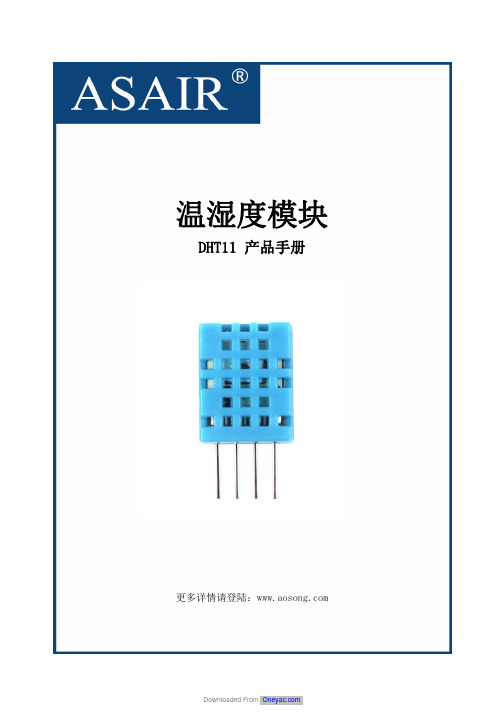
温湿度模块DHT11产品手册更多详情请登陆:湿元件和一个NTC测温元件,并与一个高性能8位单片机相连接。
他相关湿度检测控制。
引脚说明1、VDD 供电3.3~5.5V DC2、DATA 串行数据,单总线3、NC 空脚4、GND 接地,电源负极一、产品概述DHT11数字温湿度传感器是一款含有已校准数字信号输出的温湿度复合传感器。
它应用专用的数字模块采集技术和温湿度传感技术,确保产品具有极高的可靠性与卓越的长期稳定性。
传感器包括一个电容式感二、应用范围暖通空调、除湿器、农业、冷链仓储、测试及检测设备、消费品、汽车、自动控制、数据记录器、气象站、家电、湿度调节器、医疗、其三、产品亮点成本低、长期稳定、相对湿度和温度测量、品质卓越、超快响应、抗干扰能力强、超长的信号传输距离、数字信号输出、精确校准。
四、外形尺寸(单位:mm )图1产品尺寸图五、产品参数5.1相对湿度表1相对湿度性能表5.2温度表2温度性能表5.3电气特性表3电气特性[1]此精度为出厂时检验时,传感器在25℃和5V,条件下测试的精度指标,其不包括迟滞和非线性,且只适合非冷凝环境。
[2]在25℃和1m/s气流的条件下,达到一阶响应63%所需要的时间。
[3]在挥发性有机混合物中数值可能会高一些。
见说明书应用储存信息。
六、典型电路图2DHT11典型电路图微处理器与DHT11的连接典型应用电路如上图(图2)所示,DATA上拉后与微处理器的I/O端口相连。
1、典型应用电路中建议连接线长度短于5m时用4.7K上拉电阻,大于5m时根据实际情况降低上拉电阻的阻值。
2、使用3.3V电压供电时连接线尽量短,接线过长会导致传感器供电不足,造成测量偏差。
3、每次读出的温湿度数值是上一次测量的结果,欲获取实时数据,需连续读取2次,但不建议连续多次读取传感器,每次读取传感器间隔大于2秒即可获得准确的数据。
4、电源部分如有波动,会影响到温度。
如使用开关电源,温度就会跳动。
DC Butt Welding Process for Wheel-Rim
ISSN 0148 - 7191 Copyright ©1988 Society of Automotive Engineers, Inc.
Positions and opinions advanced in this paper are those of Persons wishing to submit papers to be considered for the author(s) and not necessarily those of SAE. The author presentation or publication through SAE should send the is solely responsible for the content of the paper. A process manuscript or a 300 word abstract of a proposed menusis available by which discussions will be printed with the cript to: Secretary, Engineering Activity Board, SAE. paper if it is published in SAE Transactions. For permission to publish this paper in full or in part, contact the SAE Printed in U.S.A. Publications Division.
between DC butt welding and flash butt welding. The advantage of DC butt welding is from efficiency and environment aspect. In DC butt welding, total welding time is about 0.5s and there is no flash, which is a typically harmful factor for environment and maintenance in a flash butt welding machine. The heat is generated by houle's heat due to the electrical resistance of base material and contact electrical resistance at the weld interface. Therefore, main control factors are welding current, welding time and electrode pressure. An example of welding current, voltage and electrode movement during welding is shown in Fig, 2. First, weld interface is heated and the plate edge begins to soften. As a result, the plate edge starts to become deformed by the electrode pressure at the upset stage. On the other ห้องสมุดไป่ตู้and, there is also the difference concerning the weld defect between DC and
华联电子光敏晶体管输出型光耦合器规格书 hpc357x说明书
参数名称 Characteristic
正向电流 Forward Current 正向脉冲电流 Forward Current (Pulsed ) Pulse width ≤ 100μs, frequency 100 Hz
符号 Symbol
IFM
IFP
额定值 Rating
50
1
单位 Unit mA
A
反向电压 Reverse Voltage
Downloaded From
Only after the signature or seal, the product specifications have the force of law.
Downloaded From
华联电子 Xiamen Hualian
规格书 SPECIFICATION
HPC357×
工作温度 Operating Temperature Range
TOPR
-55~110
C
贮存温度 Storage Temperature Range
TSTG
-55~125
C
回流焊接温度 Reflow Soldering (10 seconds )
Th
260
C
总耗散功率 Total Power Dissipation
VF
IF=10mA
反向电流 Reverse Current
IR
输入端子电容 Input Capacitance
CIN
VR =6V V=0V F=1MHz
集电极-发射极反向击穿电压 Collector-Emitter Reverse Breakdown Voltage
V(BR)CEO
MIL-C-81706_AMENDMENT-6
NOT MEASUREMENTSENSITIVEMIL-C-81706AMENDMENT 623 October 2000SUPERSEDINGINT. AMENDMENT 5(AS)13 November 1979AMENDMENT 410 March 1977MILITARY SPECIFICATIONCHEMICAL CONVERSION MATERIALS FOR COATINGALUMINUM AND ALUMINUM ALLOYSThis amendment forms a part of MIL-C-81706, dated 30 June 1970, and is approved for use by all Departments and Agencies of the Department of Defense.PAGE 11.2.2.1: Add:“Form IV – Premixed liquid, thixotropic (ready for use)Form V – Premeasured powder, thixotropic (ready for use after addition of water) *Form VI –Premixed liquid (ready for touch-up use in self-contained applicatordevice).”PAGE 2* 1.2.2.2: Add:“Method D – Applicator pen.”* 2.1: Under SPECIFICATIONS, Federal delete:“L-B-560 Bottle, Screw Cap (Polyethylene)TT-P-143Paint, Varnish, Lacquer, and Related Materials, Packaging, Packing,and Marking of.”AMSC N/A 1 of 7AREA MFFP DISTRIBUTION STATEMENT A. Approved for public release; distribution is unlimited.* 2.1: Under SPECIFICATIONS, Federal add:“PPP-P-1892-Paint, Varnish, Lacquer, and Related Materials; Packaging,Packing and Marking of2.1: Under SPECIFICATIONS, Military add:*“MIL-B-26701 - Bottle, Polymer, in a Combination Container, Shipping andStorage, Air Eligible (Inactive for new design)*MIL-PRF-85285 - Coating, Polyurethane, High-Solids*MIL-PRF-85582 - Primer Coatings: Epoxy, Waterborne*Change “MIL-P-23377” to “MIL-PRF-23377.”PAGE 3*Add new paragraph:“2.2Non-Government publications. The following documents form a part of this document to the extent specified herein. Unless otherwise specified, the issues of the documents that are DoD adopted are those listed in the issue of the DoDISS cited in the solicitation. Unless otherwise specified, the issues of documents not listed in the DoDISS are the issues of the documents cited in the solicitation (see 6.2).AMERICAN SOCIETY FOR TESTING AND MATERIALS (ASTM)ASTM-D3359-Standard Test Methods for Measuring Adhesion by Tape Test(Application for copies should be addressed to the American Society for Testing and Materials, 100 Barr Harbor Drive, West Conshohocken, PA 19428-2959.)”* 3.4: Delete the first sentence and substitute:“3.4 Application. The material, when furnished in the form specified in 1.2.2.1, after proper mixing, shall allow treatment of the prepared metal in accordance with the supplier’s instructions, by spray, brush, immersion, or ready-to-use applicator pen. The applicator pen solution shall not be permitted to puddle.”PAGE 4* 3.4: Add to end of paragraph “Form IV and V films shall show an average weight of 2.8 to 6.5 grams of material adhering to panels tested in accordance with the method specified in 4.5.7.The material shall cling uniformly with no visual evidence of excessive run-off or lack of film coverage.”*Table I: Add “1/” after “336.”*Table I: At end of table add “1/ Exposure time for Class 1A, Form VI, Method D materials shall be 168 hours.”PAGE 4*Add new paragraph:“3.7.3 Adhesion (wet tape) after repair (Class 1A, Form VI, Method D only). After panel repair and immersion specified in 4.5.8, the scribed panels shall exhibit no peel away and be rated at not less than 4A in accordance with ASTM-D3359. There shall be no blistering of the unscribed coated area.”PAGE 5* 3.10, delete the first sentence and substitute: “Materials conforming to this specification shall have a storage life of not less than 12 months.”PAGE 64.3.2, line 5: Delete: “five gallons” and substitute “eight one-quart bottles.”* 4.3.2, line 7: After “(see 5.2.1).” add “For Class 1A, Form VI, Method D material,the supplier shall furnish 12 applicator pens.”* 4.3.3, line 6: After “width” add “, except those required for wet tape adhesion (panels 12 through 29) shall be 5 inches in length”PAGE 7After 4.3.3.1, add new paragraph:“4.3.3.1.1 Panel preparation for adherence test. Three, 3 x 10 x 0.032 inch panels of 7075-T6 aluminum alloy shall be cleaned with toluene followed by acetone (3 x 0.032 inch x any length over 4 inches may be used). The panels shall then be marked with a pencil line 4 inches from one end. Each clean, marked panel shall be placed in a separate 600 ml beaker and weighed with the beaker to the nearest tenth of a gram.”* 4.3.3.2: Delete and substitute:“4.3.3.2 Panel treatment for class 1A material. Panels of each alloy, lettered “A” and “B”detailed, marked, and cleaned in accordance with 4.3.3 and 4.3.3.1 shall be treated as follows:Class 1A, Form VI, Method D Panels – Panels shall be treated on one side by the qualifying activity in accordance with the supplier’s instructions. All panels shall be dried at ambient conditions for 24 hours before finishing or testing. Panels marked 1 through 5 shall have edges protected by wax or other standard method.All other panels – Panels shall be treated by the qualifying activity on all surfaces in accordance with the supplier’s instructions. All panels shall be dried between 70 and 90 °F (21 and 32 °C) for 24 hours before finishing or testing, except those to be used for coating weight.”4.3.3.3: Delete and substitute:“4.3.3.3 Panel finishing for class 1A material. The A and B lettered panels numbered 7 through 29in accordance with 4.3.3 shall be finished as follows:Class 1A, Form VI, Method D (Panels 7 and 8) – Panels shall be finished with one coat of an epoxy primer conforming to MIL-PRF-23377 or MIL-PRF-85582. Panels shall be air dried for 14 days before testing.Class 1A, Form VI, Method D (Panels 12 through 20) – Panels shall be finished with one coat of epoxy primer conforming to MIL-PRF-23377 followed by, after the primer has dried, a polyurethane topcoat conforming to MIL-PRF-85285. Panels shall be air dried for 14 days before testing.Class 1A, Form VI, Method D (Panels 21 through 29) – Panels shall be finished with one coat of epoxy primer conforming to MIL-PRF-85582, followed by, after the primer has dried, a polyurethane topcoat conforming to MIL-PRF-85285. Panels shall be air dried for 14 days before testing.All other panels – Panels shall be finished as specified in 4.3.3.3.1.”PAGE 8*Table II, under Class 1A Panel Nos., after “7 to 8” add “and 12 to 29.”*Table II, under Reference paragraphs, after 4.5.3, add “and 4.5.8.”*Table II, under Requirement paragraphs, after “3.7.2” add “3.7.3.”*Table II, footnote 1/, after “respectively.” Add “Panels 12 through 29 are only required for Class 1A, Form VI, Method D materials.”*Table II, under Tests, after “Coating Weight” add ‘‘6/.”*Table II, under footnote 5/, add footnote “6/ Class 1A, Form VI, Method D materials are not subjected to coating weight test.”PAGE 9* 4.3.4.1, at end of paragraph add: “Class 1A, Form VI, Method D materials shall not undergo weight of film testing.”Insert new paragraph after 4.3.6:“4.3.7 Retention of qualification. In order to retain qualification of a product approved for listing on the Qualified Products List (QPL), the manufacturer shall verify by certification to the qualifying activity, that the manufacturer’s product complies with the requirements of this specification. Unless otherwise specified, the time of periodic verification by certification shall be in two-year intervals from the date of the original qualification, and shall be initiated by the qualifying activity. No change shall be made in formulation, raw materials or supplier(s) of raw materials, methods of manufacture, equipment, or geographic location without prior written Government approval. The Government reserves the right to re-examine the qualified product whenever deemed necessary to determine that the product continues to meet any or all of the specification requirements.”PAGE 11*Table III, under Test, after “Coating Weight” add ‘‘2/.”*Table III, under footnote 1/, add footnote “2/ Class 1A, Form VI, Method D materials shall not be subjected to coating weight test.”PAGE 13Add new paragraphs after 4.5.6:“4.5.7 Vertical adherence test. In addition to the other tests required for class 1A materials, Form IV and Form V shall be tested for ability to adhere to a vertical surface as specified in 3.4.4.5.7.1 Material preparation. One quart of the Form IV or Form V material (with required water added) shall be thoroughly mixed and allowed to stand for 24 hours. Transfer enough of the material to almost fill a 600 ml plastic beaker.4.5.7.2 Adherence. Each previously prepared panel, in accordance with 4.3.3.1.1, shall be immersed, one at a time, in the coating material up to the 4 inch pencil line, lifted vertically above the surface of the material and allowed to drain for 45 seconds. The panel shall then be transferred without rinsing to the beaker in which it was originally weighed and the beaker and the coated panel shall be re-weighed to the nearest tenth of a gram.4.5.7.3 Weight of material clinging. The weight of material clinging to the panel is equal to the original weight of the panel plus the beaker subtracted from the weight of the panel plus the coating plus the beaker. Average weight determined from the three tests shall conform to 3.4.”PAGE 13*Add new paragraphs:“4.5.8 Adhesion (wet tape) after repair (Class 1A, Form VI, Method D only).4.5.8.1 Repair procedure. Panels 12 through 29 finished as specified in 4.3.3.3 shall be abraded to a shiny substrate using a Scotch Brite wheel (see 6.8). The remainder of the topcoat shall be lightly abraded to accept refinish primer. The abraded area shall be 4 square inches. Class 1A, Form VI, Method D material shall be applied to the abraded panel and conditioned in accordance with the manufacturer’s instructions. The entire surface of panels 12 through 20 and 21 through 29 shall be refinished as specified in the appropriate section of 4.3.3.3.4.5.8.2 Immersion procedure. Painted panels shall be immersed in distilled water as follows:3 panels of each substrate and finish for 24 hours at room temperature.3 panels of each substrate and finish for 96 hours at 120°±2 °F (49°±1 °C).3 panels of each substrate and finish for 168 hours at 150°±2 °F (65.5°±1 °C). Upon completion of the immersion period, the panels shall be removed from the water, dried using a clean, dry soft cloth, and be immediately evaluated as specified in 4.5.8.3.4.5.8.3 Evaluation procedure. Each panel shall be evaluated in accordance with Method A of ASTM-D3359 except for the following:a.There shall be one “X” scribed incisions between parallel lines that are approximately 1inch apart. All incisions shall be into the substrate. The scribed area shall include theoriginal paint, overlap area, and the repair area.b.The tape, 3M Type 250 (see 6.8), shall be placed on the panel parallel to the parallelscribed lines and be smoothed by rolling a 3 pound roller over it once. Tape removal shall be as specified in ASTM-D3359.c.The incision areas shall be inspected for peel away and the unscribed areas for blistering.Conformance to 3.7.3 shall be required.”PAGE 175.2: Delete “Specification TT-P-143” and substitute: “PPP-P-1892.”5.2.1, fourth sentence: Delete and substitute “Polyethylene bottles with polyethylene screw cap closures, conforming to MIL-B-26701, shall be used for packaging of premixed liquids for touch up brush application and for powder in quantities of 5 pounds or less.”5.2.1, line 8: Delete “(see6.2)” and substitute “and the premeasured powder shall be packaged in one quart quantities with the bottle marked with the powder level and the added liquid level (see 6.2).”PAGE 18* 6.1.1: Add to end of paragraph “Class 1A, Form VI, Method D materials covered by this specification are intended for use in the formation of chemical conversion coatings for repair or touch-up applications which are corrosion preventative and improve adhesion of paint finish systems to aluminum and aluminum alloys.”PAGE 19* 6.3.2, line 1: After “(Method B)” add “and pen application (Method D).”* 6.8 Source of tape. Type 250 tape and Scotch Brite wheels are available for purchase from the 3M Company, Minneapolis, MN.NOTE: The margins of the amendment are marked with an asterisk to indicate where changes from the previous amendment were made. This was done as a convenience only and the Government assumes no liability whatsoever for any inaccuracies in these notations. Bidders and contractors are cautioned to evaluate the requirements of the document based on the entire content irrespective of the marginal notations and relationship to the last previous issue. Custodians:Preparing activity:Army – MR Navy – ASNavy – ASAir Force – 99(Project MFFP-0674)Review activities:Army – AR, AT, MINavy – OS, SHAir Force – 11Other – DS。
lenovo 联想电脑-数字下载恢复服务 使用指南说明书
Lenovo Digital Download Recovery Service (DDRS) Steps to create a Lenovo Recovery USB keythe Lenovo Digital DownloadB.Open the Lenovo Digital Download Tool, and type your Lenovo ID and password that was used when the digitaldownload order was placed. Then, click the Sign-in button.C.Follow the instructions displayed to start downloading the recovery files. For additional information on using theLenovo Digital Download Tool, go to: Using the Lenovo Digital Download Tool.Note: Recovery files are several gigabytes in size. Depending on your network connection, this process can take several hours.The Lenovo Digital Download Tool shows the time remaining to complete the process.3. Download the Lenovo USB Recovery Creator tool and create the Lenovo Recovery USB keyA.Click on the version of Lenovo USB Recovery Creator tool based on the installed Windows® version on yourcomputer:∙Lenovo USB Recovery Creator tool for Windows® 7∙Lenovo USB Recovery Creator tool for Windows® 8 or laterNote: Both the Lenovo Digital Download Tool and the Lenovo USB Recovery Creator tool must be in the same folder location in your computer.B.After all recovery files have been downloaded, open the Lenovo USB Recovery Creator tool.Note: Do not alter the recovery files or file structure after the files have been downloaded from Lenovo. Changing or deleting any file or modifying the file structure will affect the creation of the USB Recovery key.C.Insert the USB key that you want to use as a Recovery USB key into one of the USB connectors.D.In the Lenovo USB Recovery Creator tool, select the USB key you inserted and the recovery master file (*.RMF) located inthe folder where you downloaded the recovery files.Note: All data on your USB key will be deleted. Backup any data you want to save before you continue.E.Follow the instructions displayed to complete the creation of the USB recovery key. For additional information using theLenovo USB Recovery Creator tool, go to: Using the Lenovo USB Recovery Creator toolNote: At the end of the USB recovery-creation process, the tool will display a prompt asking whether you want to keep or delete the recovery files that were downloaded to your computer. If you delete the recovery files from your computer, you will not be able to create another USB recovery key.4. Using the Lenovo Recovery USB keyAfter creating the Lenovo Recovery USB key, the USB key can be used to reinstall Microsoft Windows® at any time on the computer models for which it was created. To use the USB key, insert the USB key into the Lenovo computer on which you want to restore the operating system. Then, restart the computer to begin the recovery process.3.Select the location on your computer where you want to download the recovery files. Then, click the Download button to start downloading the recovery files.Tip: Use a folder that contains no other files.Tip: Do not alter the recovery files or recovery structure after the files have been downloaded from the Lenovo. Changing or deleting any file or modifying the file structure could affect the process for creating USB Recovery Key.4.The Lenovo Digital Download Tool provides status during the download process.Tip: Recovery files are several gigabytes in size. Depending on the speed of your network connection, this process can take several hours. The Lenovo Digital Download tool shows the time remaining to complete the process.Tip: You can pause the download process by clicking the Pause button and resume later on where you left off.5.After all recovery files have been downloaded, you can create the USB Recovery key by running the Lenovo USB Recovery Creator tool.Tip: You can come back to this guide any time by clicking the Help button located on the upper-right corner of the Lenovo Digital Download tool2.On the screen, select the USB key and then click the Create USB Key button.3.When a message displays prompting you to confirm that you want to create USB Recovery key, click the Yes button to continue.Warning: If you click Yes, all data currently on the selected USB key will be deleted as part of the process. Copy any files you want to keep onto other media before you continue.4.The Lenovo USB Recovery Creator tool provides status during the process of creating the USB Recovery key.Tip: Depending on the speed of the USB key (USB 2.0 or USB 3.0) and your computer, this process can take anywhere from 15 to 45 minutes.5.At the end of the process, the tool displays a prompt asking whether you want to keep the recovery files or delete them to free up that space on your computer.Tip: Your USB recovery key is ready at this point and you can remove it from the computer. Click Yes to delete the recovery files or No, Exit to keep them and close the tool.Tip: If you keep the recovery files, you can create another USB Recovery key in the future by running the Lenovo USB Recovery Creator tool again. If you delete the files, you will not be able to re-create this USB Recovery key.6.If you chose to delete the recovery files, you need to confirm once more that you are sure that you want the files deleted. Click Yes to delete the recovery files or No, Exit to keep them and close the tool.Recovery Creator tool.If I have a problem, how can I contact support?Contact Lenovo Support at https:///lenovorecovery/email。
MIL-DTL-83420M
INCH-POUNDMIL-DTL-83420M 1April2005SUPERSEDINGMIL-DTL-83420L 20November2002DETAIL SPECIFICATIONWIRE ROPE, FLEXIBLE, FOR AIRCRAFT CONTROL,GENERAL SPECIFICATION FORThis specification is approved for use by all Departments and Agencies of the Department of Defense.1. SCOPE1.1 Scope. This specification covers the requirements for carbon steel andcorrosion resistant steel aircraft control flexible wire rope. Type I wire rope will becapable of operation within a -65 °F to +250 °F (-54 °C to +121 °C) temperature range inwind, dust, fuel, and oil spills, in wash-down and other environmental stresses and aircraft experiences. Type II wire rope will be capable of operation within a -65 °F to +200 °F(-54 °C to +94 °C) temperature range in wind, dust, fuel, and oil spills, in wash-down andother environmental stresses and aircraft experiences.1.2 Classification. The wire rope will be of the following types and compositions, as specified (see 6.2).1.2.1 Types. The types of wire rope are as follows:Type I - Nonjacketed wire ropeType II - Jacketed wire rope1.2.2 Compositions. The compositions of the wire rope are as follows:Composition A - Carbon steel, zinc, or tin over zinc coatedComposition B - Corrosion resistant steel2. APPLICABLE DOCUMENTS2.1 General. The documents listed in this section are specified in sections 3 and 4 of this specification. This section does not include documents cited in other sections of this specification or recommended for additional information or as examples. While every effort has been made to ensure the completeness of this list, document users are cautioned that they must meet all specified requirements of the documents cited in sections 3 and 4 of this specification, whether or not they are listed.2.2 Government documents.2.2.1 Specifications and standards. The following specifications and standard form a part of this document to the extent specified herein. Unless otherwise specified, the issues of these documents are those cited in the solicitation or contract.DEPARTMENT OF DEFENSE SPECIFICATIONSMIL-DTL-781 - Terminal, Wire Rope Swaging, General Specification for.MIL-PRF-5606 - Hydraulic Fluid, Petroleum Base; Aircraft, Missile andOrdnance.MIL-DTL-5624 - Turbine Fuel, Aviation, Grades JP-4 and JP-5.MIL-PRF-7808 - Lubricating Oil, Aircraft Turbine Engine, Synthetic Base.MIL-H-19457 - Hydraulic Fluid, Fire-Resistant, Non-Neurotoxic.MIL-PRF-83282 - Hydraulic Fluid, Fire Resistant, Synthetic HydrocarbonBase, Metric, NATO Code Number H-537.MIL-DTL-83420/1 - Wire Rope, Flexible, Type I, Composition A.MIL-DTL-83420/2 - Wire Rope, Flexible, Type I, Composition B.MIL-DTL-83420/3 - Wire Rope, Flexible, Type II (Jacketed), Composition A.MIL-DTL-83420/4 - Wire Rope, Flexible, Type II (Jacketed), Composition B.MIL-PRF-87937 - Cleaning Compound, Aerospace Equipment.DEPARTMENT OF DEFENSE STANDARDMIL-STD-129 - Military Marking for Shipment and Storage.(Copies of these documents are available online at / or from the Standardization Documents Order Desk, 700 Robbins Avenue, Building 4D, Philadelphia, PA 19111-5094.)2.3 Non-government publications. The following documents form a part of this document to the extent specified herein. Unless otherwise specified, the issues of these documents are those cited in the solicitation or contract.ASTM INTERNATIONALASTM A 90/A 90M - Standard Test Method for Weight [Mass] of Coating onIron and Steel Articles with Zinc or Zinc-Alloy Coatings.ASTM D 570 - Standard Test Method for Water Absorption of Plastics.ASTM D 635 - Standard Test Method for Rate of Burning and/or Extentand Time of Burning of Plastics in a Horizontal Position.ASTM D 638 - Standard Test Method for Tensile Properties of Plastics.ASTM D 648 - Standard Test Method for Deflection Temperature ofPlastics Under Flexural Load in the Edgewise Position.ASTM D 746 - Standard Test Method for Brittleness Temperature ofPlastics and Elastomers by Impact.ASTM D 790 - Standard Test Methods for Flexural Properties ofUnreinforced and Reinforced Plastics and ElectricalInsulating Materials.ASTM D 792 - Standard Test Methods for Density and Specific Gravity(Relative Gravity) of Plastics by Displacement.ASTM D 910 - Standard Specification for Aviation Gasolines.ASTM D 3418 - Standard Test Method for Transition Temperatures ofPolymers By Differential Scanning Calorimetry.ASTM E 8 - Standard Test Methods for Tension Testing of MetallicMaterials.(Copies of these documents are available from / or from ASTM International, 100 Barr Harbor Drive, West Conshohocken, PA 19428-2959.)INTERNATIONALSAESAE HS-1086 - Metals and Alloys in the Unified Number System.SAE AMS 1424 - Deicing/Anti-icing Fluid, Aircraft, SAE Type I.SAE AMS-STD-66 - Steel: Chemical Composition and Hardenability.(Copies of these documents are available from / or from SAE International, 400 Commonwealth Drive, Warrendale, PA 15096-0001.)2.4 Order of precedence. In the event of a conflict between the text of this document and the references cited herein (except for related specification sheets), the text of this document takes precedence. Nothing in this document, however, supersedes applicable laws and regulations unless a specific exemption has been obtained.3. REQUIREMENTS3.1 Specification sheets. The individual item requirements shall be as specified herein and in accordance with the applicable specification sheet. In the event of any conflict between the requirements of this specification and the specification sheet, the latter shall govern.3.2 Qualification. Wire rope (see 6.4.16) furnished under this specification shall beproducts that are qualified for listing on the applicable qualified products list at the time of award of contract (see 4.2 and 6.3). Products must be qualified by a test facility located in the continental United States or Canada (see 4.1). The qualifying activity will be advised of any plant relocation, changes in key personnel, or major process change(s) (e.g. changes in lubricant and/or jacketing material, changes in the lubricant application process, etc.) for requalification testing determinations.3.2.1 Wire rope for type II. The wire rope that is to be nylon jacketed to form type II must be qualified as type I, composition A or B, wire rope in accordance with the provisions of this specification. Upon type I wire rope being subjected to subsequent processing for qualification or manufacture as a type II wire rope, it shall not be certified or shipped as a type I wire rope. Type II wire rope shall not be remanufactured into type I wire rope.3.3 Materials and protective coating.3.3.1 Steel for composition A. High carbon steel in accordance with SAE AMS-STD-66 shall be used for composition A wire rope and shall be of one type. The carbon steel shall be capable of meeting the requirements of this specification.3.3.2 Steel for composition B. Corrosion resistant steel S30200 or S30400 in accordance with SAE HS-1086 shall be used for composition B, type I and II, wire rope.3.3.3 Protective coating. Composition A wires shall be thoroughly and uniformly coated by the methods specified in 3.3.3.1 or 3.3.3.2 (see 6.2).3.3.3.1 Zinc coating for composition A. Zinc coating of composition A wires shall be by the hot dipped or electroplated process and shall conform to the following:Wire diameterMinimum weight of zinc coating (oz./sq. ft.)0.005 to 0.010 inch 0.03Over 0.010 to 0.015 inch 0.05Over 0.015 to 0.028 inch 0.10Over 0.028 to 0.060 inch 0.203.3.3.2 Tin coating for composition A. Tin coating over zinc of composition A wires shall be by the hot-dipped or electroplated process and shall conform to the following:Wire diameterMinimum weight of tin coating (oz./sq. ft.)0.005 to 0.010 inch 0.003 Over 0.010 to 0.015 inch 0.005 Over 0.015 to 0.028 inch 0.010 Over 0.028 to 0.060 inch 0.0153.3.3.3 Nylon jacketed coating for type II. The nylon jacketing (see 6.4.2) material shall meet the requirements of this specification as specified in 3.3.3.3.1 and shall be extruded over the rope. Only virgin nylon material shall be used in coating on type II wire rope.3.3.3.3.1 Nylon jacketing physical and mechanical properties. The nylon used to jacket the wire rope shall be in accordance with ASTM D 789 and meet the requirements listed below when tested as specified in the following paragraphs:paragraph Property Requirement Test Ultimate tensile strength 5,000 psi minimum 4.5.1Elongation 250 percent minimum 4.5.1Specific gravity 0.95 to 1.09 4.5.2Water absorption 1.5 percent maximum 4.5.3Brittleness -65 °F (-54 °C) maximum 4.5.4Stiffness 35,000 psi minimum 4.5.5Heat deflection 100/35 °C at 66/264 psi minimum 4.5.6Melting range 320 °F to 364 °F (160 °C to 190 °C) 4.5.7Burn resistance 4 inch/minimum 4.5.83.3.4 Lubricant. Each wire of the wire rope shall be coated with a friction-preventive, non-corrosive lubricant. As a minimum, the lubricant shall operate at temperatures from -65 °F to +250 °F(-54 °C to +121 °C). Any change in lubricant is considered a major process change and may require requalification testing (see 3.2).3.4 Construction.3.4.1 Wire. The wire (see 6.4.15) used in steel wire rope cable shall be cylindrical, smooth, and of uniformly high quality.3.4.1.1 Wire properties. Tensile strengths of wire and wire sizes shall be such that wire rope will be capable of meeting the requirements of this specification.3.4.1.2 Preforming (see 6.4.9) of wires and strands. The individual wires and strands composing the wire rope shall be shaped into the exact helical position they will have in the finished wire rope, so that if the wire rope is cut or severed there is no tendency for the measured diameter of the wire rope at the unseized cut ends to increase by more than the amount specified in table I.3.4.1.3 Splicing and joining. All splices or joints in wires less than 0.008 inch may be longitudinally twisted. All wire sizes of 0.008 inch or more shall be brazed or welded. Any joints in individual wires in any layer of a strand (see 6.4.12) shall not be closer than 20 feet except as specified in 3.4.1.3.1 (see 4.5.2).3.4.1.3.1 Twist-off. When a twist-off (see 6.4.14) occurs during fabrication of the 7-wire layer of a 19-wire strand (see 3.4.1.3), splices and joints in individual wires may be as close as 18 inches.3.4.2 Wire rope lengths. The wire rope shall be furnished on reels in lengths specified by the procuring activity. There will be no more than two pieces of wire rope on the reel. The shortest piece shall be a minimum of 20 percent of the reel length. The distance to the break point on the reel shall be marked on the reel and package (see 3.6.3).3.4.3 Wire rope construction. Flexible steel wire rope shall be 3 x 7, 7 x 7, or 7 x 19 construction and shall be regular lay (see 6.4.10) for the respective diameters, the dimensional tolerances, and the physical properties as specified in tables I and II.3.4.3.1 Construction 3 x 7. Wire rope of this construction shall consist of 3 strands of7 wires each laid together without a core. Each strand shall consist of a layer of 6 wires laid around a center wire (see 6.4.1) in a left-hand direction. The 3 strands shall be laid together in a right-hand direction. The length of lay (see 6.4.3 and 6.4.4) of the 6 outer wires in each strand shall not exceed 70 percent of the lay of the finished rope. The length of lay of the finished wire rope shall not be more than 7 nor less than 5 times the nominal wire rope diameter (see 6.4.17).3.4.3.2 Construction 7 x 7. Wire rope of this construction shall consist of 6 outer strands of 7 wires each laid around a strand core (see 6.4.13) of 7 wires. The 6 outer strands shall consist of a layer of 6 wires laid around a center wire in a left-hand direction. The strand core shall consist of a layer of 6 wires laid around a center wire in a right-hand direction. The 6 outer strands shall be laid around the core in a right-hand direction. The length of lay of the outside 6 wires in each of the 6 outside strands and the outside 6 wires of the strand core shall not exceed 60 percent of the lay of the finished wire rope. The length of the lay of the finished wire rope shall be not more than 8 nor less than 6 times the nominal rope diameter.3.4.3.3 Construction 7 x 19. Wire rope of this construction shall consist of 6 outer strands of 19 wires each laid around a strand core of 19 wires. The 6 outer strands shall each consist of a layer of 6 wires laid around a center wire in a left-hand direction and a layer of 12 wires laid over the 7-wire strand in a left-hand direction. The strand core shall consist of a layer of 6 wires laid around a center wire in a right-hand direction and a layer of 12 wires laid around the 7-wire strand in the right-hand direction. The 6 outer strands shall be laid around the core in a right-hand direction. The length of lay of the inside layer of 6 wires in each of the 6 outer strands and the one strand core shall not exceed 60 percent of the outside layer of 12 wires in each strand. The length of lay of the outside layer of 12 wires in each of the 6 outside strands and the strand core shall not exceed 50 percent of the lay of the finished wire rope. The length of the lay of the finished wire rope shall not be more than 8 nor less than 6 times the nominal rope diameter.3.5 Performance.3.5.1 Operating range. The wire rope shall be capable of operation in wind, dust, fuel, oil spills, wash-down, and other aircraft environmental stresses and experiences at the temperature ranges specified in paragraphs 3.5.1.1 and 3.5.1.2.3.5.1.1 Type I. Type I wire rope shall be capable of operating within a -65 °F to +250 °F (-54 °C to +121 °C) temperature range.3.5.1.2 Type II. Type II wire shall be capable of operating within a -65 °F to +200 °F (-54 °C to +94 °C) temperature range.3.5.2 Wire flexibility.3.5.2.1 Ductility of steel. Composition A or B wire shall not fracture when wrapped in accordance with4.4.1.1 prior to wire rope fabrication.3.5.2.2 Adherence of coating. The tin or zinc coating shall not crack or flake when wrapped in accordance with4.4.1.2 prior to wire rope fabrication. Loosening or detachment of small superficial particles of coating (formed by mechanical polishing of the surface) during the adhesion test is acceptable.3.5.3 Breaking strength. The type I, composition A and B, wire ropes shall have the minimum breaking strength (MBS) (see 6.4.7) as shown in table I.3.5.4 Endurance, type I wire rope. Each wire rope size of each construction shall be capable of withstanding the respective tension loads, reversals, and breaking strength shown in table III.3.5.5 Endurance, type II wire rope. Each wire rope size of each construction shall be capable of withstanding the respective tension loads, reversals, and breaking strength shown in table IV. There shall be no cracking or deterioration of the nylon coating after the test.3.5.6 Stretch limits. The stretch in each wire rope size of each construction shall not exceed 1.5 percent when it is loaded to 60 percent of the MBS as shown in table I.3.5.7 Test load. Each wire rope size of each construction shall carry 80 percent of its respective MBS load, as shown in table I, without any failures of the individual wires in the rope.3.5.8 Jacket characteristics, type II. The nylon jacketed wire rope shall have characteristics in accordance with the requirements of table II.3.5.9 Low temperature flexibility, type II. Each size of each type II jacketed rope shall be bent or flexed at a temperature of -65 °F (-54 °C) without any deleterious effects such as cracking of the nylon or separation from the wire rope.3.5.10 Resistance to fluids. Type II wire rope shall show no deleterious effects when immersed in the fluids listed in4.4.10.3.6 Identification of product. The wire rope shall be identified in accordance with the following:3.6.1 Identification by number. Each manufacturer shall assign a significant identification number on each manufacturing reel of wire rope. When the wire rope on the manufacturing reel is cut to specified lengths for transfer to the shipping reel (see 6.4.11), eachshipping reel shall be marked with the identification number of the manufacturing reel.3.6.2 Identification by color tracer filament. Each manufacturer shall identify every wire rope by the use of color filaments manufactured into the rope. The specification preparing activity will assign a combination of colors to each manufacturer desiring qualification. The inclusion of color tracing filaments alone does not designate that the wire rope is in full conformance with this specification or has met qualification requirements, but only serves to identify the manufacturer. Color tracer filaments are not mandatory in 3 x 7 construction.3.6.3 Identification of reels and shipping containers. Each shipping reel and shipping container shall be marked in accordance with the requirements of MIL-STD-129. The following information shall be included:a. Stock No. or identification as specified in the contract. 1/b. Size (include diameter of wire rope, outside diameter of nylon).c. Name of wire rope manufacturer.d. Name of contractor.e. Contractor order number.f. Type of wire rope, composition, protective coating for composition A, and specification number (MIL-DTL-83420).g. Date of manufacture (month/year).h. For reels with 2 lengths of wire rope, record distance from outside end to separation point and total length of wire rope on the reel.i. Manufacturing reel/lot number.1/ The contractor shall enter the National Stock Number (NSN) specified in the contract or as furnished by the procuring activity. Space shall be left for the NSN when not available.3.7 Workmanship and finish. All details of workmanship and finish shall be in accordance with the best practice for high quality aircraft wire rope consistent with the requirements of this specification. The finished cable shall be uniform in construction and securely laid, free from kinks, loose wires, loose strands, or other defects (see4.4.2). Protruding wires are considered a defect and not more than one broken wire will be accepted in 1000 feet of wire rope.3.7.1 Physical appearance, type II. The nylon jacket shall be uniform in outside diameter (O.D.) and in wall thickness as specified in table II and shall be uniform in appearance. The nylon jacket shall be translucent and shall be homogeneous and uniform in consistency. The jacketed wire rope shall have no cracks or seams, or foreign material in the nylon on the surface.Any deleterious effects, such as cracking or separating from the wire rope, shall be cause for rejection.3.7.1.1 Concentricity. The differences in wall thickness as determined in4.4.2.1 shall not exceed 20 percent.4. VERIFICATION4.1 Classification of inspection. The inspection and testing of the wire rope shall be classified as follows:a. Qualification inspection (see 4.2).b. Conformance inspection (see 4.3).4.2 Qualification inspection.4.2.1 Qualification inspection samples. When conducting qualification tests specified herein, one sample lot for each size and construction of wire rope listed in tables I and II, for which qualification is desired, shall be taken after any discard has been removed from the head or starting end of the first manufacturing reel for each lot of wire rope.4.2.1.1 Lot. A qualification inspection lot shall consist of 50 feet of wire rope of the same construction and diameter produced continuously by one machine or by one series of progressive processing machines.4.2.2 Qualification testing. Qualification tests shall be performed for each size and construction of wire rope for which qualification is desired as specified in table V.4.2.3 Qualification for type II. Qualification for type II wire rope shall be finalized after the following:a. Receipt from the nylon manufacturer of a test report that includes, as a minimum, the results of the tests specified in 4.5.b. Successful completion of the remaining qualification tests for type II wire rope.4.2.3.1 Duplication nylon certification. If two or more type II wire rope sizes are submitted for qualification, and the nylon coating is of the same type and grade, copies of the original test certification on the particular type and grade of nylon will satisfy the requirement as specified in 4.2.3 and 4.3.4.4.2.4 Maintenance of qualification. To maintain qualification, the manufacturer must be able to demonstrate that the company still has the capabilities and facilities necessary to produce the items. The qualifying activity will request appropriate documentation demonstrating this capability at the time qualification retention is required (at least 2-year intervals).4.3 Conformance inspection. Conformance inspection shall consist of individual testsand sampling tests.4.3.1 Individual tests. Each size wire rope of each type, composition, and construction furnished under each contract or order shall be subject to the following tests as described under4.4 (see table V):a. Ductility of steel (4.4.1.1).b. Adherence of coating (4.4.1.2).c. Examination of product (4.4.2).d. Concentricity tests for type II wire rope (4.4.2.1).e. Conformance test to preforming of cable (4.4.2.2).f. Color-coding identification (4.4.11).4.3.2 Sampling plan.4.3.2.1 Sample.4.3.2.1.1 Wire rope. When conducting the sampling tests specified herein, one continuous sample of sufficient length shall be taken after any discard has been removed from the head or starting end of the first manufacturing reel for each lot of wire rope.4.3.2.1.2 Wire. When conducting the sampling tests specified herein, one random sample of wire, of sufficient length to meet testing requirements, shall be taken from the wire lot.4.3.2.2 Lot.4.3.2.2.1 Wire rope. A lot shall consist of not more than 20,000 feet of wire rope of the same construction and diameter produced continuously by one machine or by one series of progressive processing machines.4.3.2.2.2 Wire. A lot shall consist of wire of one size produced from the same heat of steel in one continuous process.4.3.2.3 Specimen. A specimen is a section of wire rope or wire cut from a sample for the performance of a testing method. All specimens shall be taken from the lot furnished under that specific order.4.3.3 Sampling tests. The conformance sampling tests shall be performed in accordance with the paragraphs listed in table V.4.3.4 Certification. For each contract or order, the wire rope manufacturer shall certify that the product satisfactorily passed the conformance inspections (see 4.3.1 and 4.3.3) of this specification. The certification shall include, as a minimum, actual results of the tests specified herein and shall be retained on file at the manufacturer's facility for a minimum of 7 years.4.3.5 Nylon certification. For each contract or order, a certification from the nylonmanufacturer shall verify that the nylon meets the requirements of this specification (3.3.3.3 and 3.3.3.3.1) (see 6.3). The certification will be retained on file at the manufacturer's facility for a minimum of 7 years.4.4 Test methods.4.4.1 Wire flexibility.4.4.1.1 Ductility of steel. A specimen from the wire sample shall be wrapped in a way that does not cause indenting. The wire shall be wrapped around a cylindrical mandrel for 2 complete turns in a close helix at a rate not exceeding 15 turns per minute. The cylindrical mandrel diameter shall be equal to the nominal wire diameter being tested for composition B, and two times the nominal diameter being tested for composition A.4.4.1.2 Adherence of coating. A specimen from the tin or zinc coated wire sample shall be capable of being wrapped at a rate not to exceed 15 turns per minute in close helix of at least 2 turns around a cylindrical mandrel equal to 2 times the nominal diameter of the wire under tests without cracking or flaking the tin or zinc coating to such an extent that any tin or zinc can be removed by rubbing with the bare finger.4.4.2 Examination of product. Each sample of wire rope shall be visually examined for workmanship and finish to determine compliance with 3.7.4.4.2.1 Concentricity test for type II wire rope. All type II wire rope shall be examined for concentricity as specified in 3.7.1.1. The wall thickness shall be measured 180 degrees apart in two 90 degrees planes. The percent variation in wall thickness shall be calculated as follows: Difference between the two measurements C and DPercent variation = ------------------------------------------------------------------------- x 100≤20%Smaller of the two measurements4.4.2.2 Conformance test to preforming of wire rope. To test wire rope for conformity to values shown in table I for increase in diameter, the wire rope shall be mechanically cut with a cutter having constricting jaws. A plain shear with straight blades distorts the product and may void the test. After cutting, the wire rope shall be measured by passing the wire rope through ahole drilled to a diameter increased as shown in table I under "Allowable increase in diameter at cut end" or by using a shadowgraph with suitable magnification. The allowable increase in diameter shall be applied to the actual diameter of the wire rope being tested.4.4.3 Breaking strength type I, composition A and B. A specimen for each size and construction of wire rope shall be selected from the sample from each lot. The specimen shall be no less than 24 inches in length, and where necessary, swaged terminals conforming toMIL-DTL-781 (do not use ball end fittings) and accompanying hardware may be used to facilitate installation of the specimen in the jaws of the testing machine. The length of wire rope sample under load shall be no less than 10 inches. The breaking strength shall be determined by use of a tensile testing machine in accordance with applicable requirements of ASTM E 8. The breaking strength shall conform to the requirement of table I. In case of failure due to an unsatisfactory end termination, the test will be disregarded and a new test conducted.4.4.4 Endurance testing for type I. The test set-up for the endurance tests for all type I wire rope shall conform to figure 1. The total travel of the wire rope in one direction shall be 13.5 inches. The test sheaves shall be made of steel and shall conform to the dimensions of figure 2 and the individual wire diameters in table VI. The application of lubricant to the endurance test sample, in addition to the lubricant applied during the manufacture of wire rope, shall not be permitted either before or during the endurance test.4.4.4.1 Endurance testing at –65°F (-54°C) for type I, composition A. An endurance test at -65°F (-54°C) shall be conducted for each type I, composition A, wire rope diameter and construction specified in 4.4.4. The number of reversals and tension loads shall be as indicated in table III. After the endurance test at -65°F (-54°C), a test specimen that is that portion of the wire rope that passes over the test sheave during the endurance test shall be selected for breaking strength tests. From this specimen, two samples representing the top and bottom sheave of the specimen shall be subjected to a breaking strength determination as specified in 4.4.3, except the breaking strength of each sample shall be equal to or greater than that specified in table III.4.4.4.2 Endurance test at room temperature for type I, composition A and B. An endurance test at room temperature shall be conducted for each type I, composition A and B, wire rope diameter and construction as specified in table III. The number of reversals and tension loads shall be as indicated in table III. After the endurance test at room temperature, a test specimen that is that portion of the wire rope that passes over the test sheave during the endurance test shall be selected for breaking strength tests. From this specimen, two samples representing the top and bottom sheave of the specimen shall be subjected to a breaking strength determination as specified in 4.4.3, except the breaking strength of each sample shall be equal to or greater than that specified in table III.4.4.5 Endurance testing for type II. The test set-up for the endurance tests of type II nylon jacketed wire rope shall conform to figure 1. The total travel of the wire rope in one direction shall be 13.5 inches. The test sheaves shall be made of steel and shall conform to the dimensions of figure 2 and the individual wire diameters in table VII which conform to the O.D. size of the nylon coating, and test loads which conform to the wire rope size.。
PT100说明书
USER INSTRUCTIONSDIMENSIONSThe transmitter is configured from a standard IBM compatible PC by using the IPRO software version 4.14 or later . The latest version of IPRO can be downloaded from http://www.inor .com. When thetransmitter is set from a PC no calibration is needed.The transmitter must not be connected to a computer, when the transmitter is in hazardous area.The transmitter is polarity protected and will not be damaged by connecting the power supply with the wrong polarity, but the output will be 0 mA.The maximum load in the output loop depends on the supply voltage, see ”DATA shortform”The transmitter continuosly supervises the isolationresistance in thermocouples and 3-wire-connected Pt100 including the connection wires. If the isolation resistance is low it causes error in the measu-rements and consequently a faulty ouptput. The transmitter indicates low isolation resistance by forcing the output to a preprogrammed value. This function requires setting by the PC-program IPRO and the use of a temperature sensor with an extra wire.Sensor wire check: the transmitter uses a pulsating technique to monitor sensor break or sensor shortened to avoid measuring errors. This pulsating signal may interfere with some electronic calibrators. By selecting ”Sensor Break = None” in the IPRO software and download the configuration into the transmitter the pulsating signal is turned off.IPAQ-H is a universal and intelligent 2-wire In-head transmitter for temperature and other measurement applications in industrial environment.IPAQ-HX is the Intrinsic Safe version for use in Ex-applications.Intelligent 2-wire In-head TemperatureTransmitterCONFIGURATIONThe IPAQ-H/HX transmitter must be powered, when you configure the transmitter, (see ”Connections” fig.1). If IPRO (the IPAQ software) isn’t installed in your PC, install the software (follow the instructions in ”IPRO User instructions”).For keeping the safety of the internal circuits in the IPAQ-HX, always use Ex-power supply or a zener barrier with limitations according to Ex-data and IPRO-X configura-tion cable when making a configuration of the transmitter.When choosing differential temperature measuments with Pt100 be sure to select ”sensor break” = none.Configuration from PC is ”on-line”, that is, the transmitter can be con-figured while in operation if the area is known to be non-hazardous. The output is frozen while transmission from PC to IPAQ take place. When transfer is done the transmitter uses the new parameters.!!86BIQ00015 2010-11ATEXMEASURE OF SUCCESSThe user instruction must be read prior to adjustment and/or installation.All information subject to change without notice.MEASURE OF SUCCESSThis product should not be mixed with other kind of scrap, after usage.It should be handled as an electronic/electric device., www.inor.semm/inchesINOR Process AB , PO Box 9125, SE-200 39 Malmö, Sweden,Phone: +46-40-31 25 60, Fax: +46-40-31 25 70, E-mail: support@inor .se INOR Transmitter OY , Unikkotie 13, FI-01300 Vantaa, Finland,Phone:+358-10-421 7900, Fax: +358-10-421 7901, E-mail: support.fi@inor .se INOR Transmitter GmbH , Am Bocksborn 5,D-63571 Gelnhausen, Germany,Phone: +49-6051 14807, Fax: +49-6051 14806, E-mail: support.de@inor .se KROHNE Temperature Division INOR , 7 Dearborn Road,Peabody, MA 01960, USA,Phone: +1-978-826 6900, Fax: +1-978-535 3882, E-mail: inor-info@Item Part No.IPAQ-H, isolated 70IPH00001IPAQ-HX, isolated (ATEX) 70IPHX0001IPAQ-HX, isolated (FM, CSA) 70IPHX1001Software and cableConfiguration kit IPRO with cables 70CFG00092AccessoriesSurface mounting box 70ADA00008Rail mounting box 70ADA00009Head mounting kit 70ADA00012Rail mounting kit70ADA00013LIMITED WARRANTYINOR Process AB, or any other affiliated company within the Inor Group (hereinafter jointly referred to as ”Inor”), hereby warrants that the Product will be free from defects in materials or workmanship for a period of five (5) years from the date of delivery (”Limited Warranty”). This Limited Warranty is limited to repair or replacement at Inor’s option and is effective only for the first end-user of the Product. Upon receipt of a warranty claim, Inor shall respond within a reasonable time period as to its decision concerning: 1 Whether Inor acknowledges its responsibility for any asserted defect in materials or workmanship; and, if so, 2 t he appropriate cause of action to be taken (i.e. whether a defective product should be replaced or repaired by Inor).This Limited Warranty applies only if the Product: 1 is installed according to the instructions furnished by Inor; 2 is connected to a proper power supply; 3 is not misused or abused; and 4 there is no evidence of tampering, mishandling, neglect, accidenta damage, modification or repair without the approval of Inor or damage done to the Product by anyone other than Inor .This Limited Warranty is provided by Inor and contains the only express warranty provided.INOR SPECIFICALLY DISCLAIMS ANY EXPRESS WARRANTY NOT PROVIDED HEREIN AND ANY IMPLIED WARRANTY, GUARANTEE OR REPRESENTATION AS TO SUITABILITY FOR ANY PARTICULAR PURPOSE, PERFORMANCE, QUALITY AND ABSENCE OF ANY HIDDEN DEFECTS, AND ANY REMEDY FOR BREACH OF CONTRACT, WHICH BUT FOR THIS PRO-VISION, MIGHT ARISE BY IMPLICATION, OPERATION OF LAW, CUSTOM OF TRADE OR COURSE OF DEALING, INCLUDING IMPLIED WARRANTIES OF MER-CHANTABILITY AND FITNESS FOR A PARTICULAR PURPOSE. EXCEPT AS PROVIDED HEREIN, INOR FURTHER DISCLAIMS ANY RESPONSIBILITY FOR LOSSES, EXPENSES, INCONVENIENCES, SPECIAL, DIRECT, SECONDARY OR CONSEQUENTIAL DAMAGES ARISING FROM OWNERSHIP OR USE OF THE PRODUCT.Products that are covered by the Limited Warranty will either be repaired or replaced at the option of Inor. Customer pays freight to Inor, and Inor will pay the return freight by post or other “normal” way of transport. If any other type of return freight is requested, customer pays the whole return cost.CONNECTIONSORDERING TABLEIPAQ-HX EX-DATAEx ia IIC T4-T6IPAQ-H/HX are designed to fit inside connection heads type DIN B or larger .The larger center hole, dia. 7 mm/0.28 inch (see ”Dimensions”), facilitates the pulling through of the sensor leads or an insert tube, greatly simplifying the mounting procedure.IPAQ-HX must be installed in an enclosure having an Ingress Protection suitable for the actual use but at least IP20.If IPAQ-HX is mounted in a housing (head) made of light metals and installed in hazardous area make sure the content of magnesium (Mg) in the light metal is less than 6%. If IPAQ-HX is mounted in a housing which is isolated from ground and can be charged to an ignition capable level, then the housing shall be electrostatically grounded when installed in hazardous area.Connect input, output and power supply acc. to fig. 1-9.A convinient way to install the transmitter is to use the INOR moun-ting kits for in-head and DIN rail mounting, (see ”Ordering table”). In order to minimize measuring errors make sure the connecting screws are tightened enough.Fig 10.Power supply: IPAQ-H6.5 to 36 VDC IPAQ-HX 8 to 30 VDC Isolation in/out: 1500 VAC Output:4-20 mAOperating temperature: -40 to +50 °C (T6)°C (T5)°C (T4)! !Output (current loop)U i ≤ 30 VDC I i ≤ 100 mA P i ≤ 900 mW L i ~ 0 mH C i ~ 0 nFInput (sensor) U o ≤ 30 VDC I o ≤ 25 mA P o ≤ 188 mW L o ~ 50 mHC o ~ 66 nFIPAQ-HX must be powered from an intrinsic safe power supply or zener barrier, placed outside the hazardous area.Also see Control Drawing 88DRW00023.Approval FM, J.I 0D6A8.AX, CSA 2007 Certificate 1863602Class I, Division 1, Group A, B, C and D Control Drawing 3-7851。
MIL-STD-202G_NOTICE-1
MIL-STD-202GNOTICE 118 July 2003DEPARTMENT OF DEFENSETEST METHOD STANDARDELECTRONIC AND ELECTRICAL COMPONENT PARTSTO ALL HOLDERS OF MIL-STD-202G:1. THE FOLLOWING PAGES OF MIL-STD-202G HAVE BEEN REVISED AND SUPERSEDE THE PAGES LISTED:METHOD NEW PAGE DATE SUPERSEDED PAGE DATE7 18 July 2003 7 8 February 2002106G 1 8 February 2002 1 REPRINTED WITHOUT CHANGE 106G 2 18 July 2003 2 8 February 2002107G 3 28 March 1984 3 REPRINTED WITHOUT CHANGE 107G 4 18 July 2003 4 28 March 1984112E 7 18 July 2003 7 11 October 1988112E 8 11 October 1988 8 REPRINTED WITHOUT CHANGE 2. THE FOLLOWING TEST METHODS OF MIL-STD-202G HAVE BEEN REVISED AND SUPERSEDE THE TESTMETHODS LISTED:NEW METHOD DATE SUPERSEDED METHOD DATE 303A 18 July 2003 303 6 February 1956305A 18 July 2003 305 24 October 19563. RETAIN THIS NOTICE PAGE AND INSERT BEFORE THE TABLE OF CONTENTS.4. Holders of MIL-STD-202G will verify that the changes indicated above have been entered. This notice page will be retained as a check sheet. This issuance, together with appended pages, is a separate publication. Each notice is to be retained by stocking points until the standard is completely revised or canceled.5. The margins of this notice are marked with asterisks to indicate where changes were made. This was done as a convenience only and the Government assumes no liability whatsoever for any inaccuracies in these notations. Bidders and contractors are cautioned to evaluate the requirements of this document based on the entire content irrespective of the marginal notations and relationship to the last previous issue.Custodians: Preparing activity:Army - CR DLA - CCNavy - ECAir Force - 11 (Project 59GP-0186) Review activities:Army - AR, AT, AV, CR4, MI, SM, TENavy - AS, OS, SHAir Force - 19, 99NSA - NSAMSC N/A FSC 59GP DISTRIBUTION STATEMENT A. Approved for public release; distribution is unlimited.NOTICE 118 July 2003NUMERICAL INDEX OF TEST METHODS Test MethodNumberDate TitleEnvironmental tests (100 class)101E 102A 103B 104A 105C 106G 107G 108A 109C 110A 111A 112E 8 February 2002Cancelled12 September 196324 October 195612 September 19638 February 200228 March 198412 September 19638 February 200216 April 197316 April 197311 October 1988Salt atmosphere (corrosion) (formerly called salt spray)Superseded by Method 107 (see note on Method 102)Humidity (steady state)ImmersionBarometric pressure (reduced)Moisture resistanceThermal shockLife (at elevated ambient temperature)ExplosionSand and dustFlammability (external flame)SealPhysical characteristics tests (200 class)201A 202D 203C 204D 205E 206 207B 208H 209 210F 211A 212A 213B 214A 215K 216 217A 24 October 1956Cancelled8 February 20021 April 1980Cancelled12 September 19638 February 200231 January 199618 May 19628 February 200214 April 196916 April 197316 April 197328 March 19848 February 2002Cancelled8 February 2002VibrationSuperseded by Method 213 (see note on Method 202)Random dropVibration, high frequencySuperseded by Method 213 (see note on Method 205)Life (rotational)High-impact shockSolderabilityRadiographic inspectionResistance to soldering heatTerminal strengthAccelerationShock (specified pulse)Random vibrationResistance to solventsSuperseded by Method 210 (see note on Method 216)Particle impact noise detection (PIND)Electrical characteristics tests (300 class)301302 * 303A304 * 305A306307308309310311312 6 February 19566 February 195618 July 200324 October 195618 July 200324 October 195624 October 195629 November 196127 May 196520 January 196714 April 196916 April 1973Dielectric withstanding voltageInsulation resistanceDC resistanceResistance temperature characteristicCapacitanceQuality factor (Q)Contact resistanceCurrent-noise test for fixed resistorsVoltage coefficient of resistance determination procedureContact-chatter monitoringLife, low level switchingIntermediate current switching7NOTICE 118 July 2003METHOD 106GMOISTURE RESISTANCE1. PURPOSE. The moisture resistance test is performed for the purpose of evaluating, in an accelerated manner, the resistance of component parts and constituent materials to the deteriorative effects of the high-humidity and heat conditions typical of tropical environments. Most tropical degradation results directly or indirectly from absorption of moisture vapor and films by vulnerable insulating materials, and from surface wetting of metals and insulation. These phenomena produce many types of deterioration, including corrosion of metals, physical distortion and decomposition of organic materials, leaching out and spending of constituents of materials; and detrimental changes in electrical properties. This test differs from the steady-state humidity test (method 103 of this standard) and derives its added effectiveness in its employment of temperature cycling, which provides alternate periods of condensation and drying essential to the development of the corrosion processes and, in addition, produces a "breathing" action of moisture into partially sealed containers. Increased effectiveness is also obtained by use of a higher temperature, which intensifies the effects of humidity. The test includes low temperature and vibration subcycles (when applicable, see 3.4.2) that act as accelerants to reveal otherwise indiscernible evidence of deterioration since stresses caused by freezing moisture and accentuated by vibration tend to widen cracks and fissures. As a result, the deterioration can be detected by the measurement of electrical characteristics (including such tests as dielectric withstanding voltage and insulation resistance) or by performance of a test for sealing. Provision is made for the application of a polarizing voltage across insulation to investigate the possibility of electrolysis, which can promote eventual dielectric breakdown. This test also provides for electrical loading of certain components, if desired, in order to determine the resistance of current-carrying components, especially fine wires and contacts, to electro-chemical corrosion. Results obtained with this test are reproducible and have been confirmed by investigations of field failures. This test has proven reliable for indicating those parts which are unsuited for tropical field use.2. APPARATUS.2.1 Chamber. A test chamber shall be used which can meet the temperature and humidity cycling specified on figure 106-1. The material used to fabricate the platforms and standoffs, which support the specimens, shall be non-reactive in high humidity. Wood or plywood shall not be used because they are resiniferous. Materials shall not be used if they contain formaldehyde or phenol in their composition. Provisions shall be made to prevent condensate from the chamber ceiling dripping onto the test specimens.2.1.1 Opening of the chamber door. During the periods when the humidity is ascending or descending, the chamber door should not be opened. If the chamber door must be opened, it should be opened during the 16th hour through the 24th hour of an individual cycle. While the chamber is at 25°C (77°F), and the relative humidity tolerance must be maintained, the chamber door should be opened only for a short period of time.2.1.2 Water. Steam, or distilled and demineralized, or deionized water, having a pH value between 6.0 and 7.2 at 23°C (73.4°F) shall be used to obtain the specified humidity. No rust or corrosive contaminants shall be imposed on the test specimens by the test facility.3. PROCEDURE.3.1 Mounting. Specimens shall be mounted by their normal mounting means, in their normal mounting position, but shall be positioned so that they do not contact each other, and so that each specimen receives essentially the same degree of humidity.3.2 Initial measurements. Prior to step 1 of the first cycle, the specified initial measurements shall be made at room ambient conditions, or as specified.REPRINTED WITHOUT CHANGE METHOD 106G8 February 20021 of 4NOTICE 1NOTES:1. Allowance of 100 percent RH is intended to avoid problems in reading values close to 100 percent RH, butactual chamber operation shall be such so as to avoid condensation.2. Unless otherwise specified, the steady state temperature tolerance is ±2°C at all points within the immediatevicinity of the specimens and the chamber surfaces.3. Rate of change of temperature is unspecified; however, specimens shall not be subjected to radiant heat fromchamber-conditioning processes.4. Circulation of air in the chamber shall be at a minimum cubic rate per minute equivalent to 5 times the volumeof the chamber.FIGURE 106-1. Graphical representation of moisture-resistance test.Supersedes page 2 of MIL-STD-202GMETHOD 106G8 February 20022NOTICE 1 18 July 2003TABLE 107-II. Exposure time in air at temperature extremes.Weight of specimenMinimum time (for steps 1 and 3)1 ounce (28 grams and below)Above 1 ounce (28 grams) to .3 pound (136 grams), inclusiveAbove .3 pounds (136 grams) to 3 pounds (1.36 kilograms), inclusiveAbove 3 pounds (1.36 kilograms) to 30 pounds (13.6 kilograms), inclusive Above 30 pounds (13.6 kilograms) to 300 pounds (136 kilograms), inclusive Above 300 pounds (136 kilograms)Hours1/4 (or as specified)½ 1 2 4 8TABLE 107-III. Thermal shock conditions (liquid).Test condition Number of cycles Test condition Number of cycles Test condition Numberof cyclesTest condition Numberof cycles Step AA 5 BB 5 CC 5 DD 5 AA-1 15 BB-1 15 CC-1 15 DD-1 15 AA-2 25 BB-2 25 CC-2 25 DD-2 25 Temperature Time Temperature Time Temperature TimeTemperature Time1 2 °C -0 +2, -10 100 +10, -2 See table 107-V See table 107-V °C -65 +0, -10 125 +10, -0 See table 107-V See table 107-V °C-65 +0, -10150 +10, -0See table107-V See table 107-V°C-65 +0, -10200 +10, -0See table107-V See table 107-VREPRINTED WITHOUT CHANGE METHOD 107G28 March 19843NOTICE 118 July 2003TABLE 107-IV. Suggested thermal fluids. 1/ 2/1/ See 2.2.2/ Ethylene glycol shall not be used as a thermal shock test fluid.3/ Tap water is indicated as an acceptable fluid for this temperature range. Its suitability chemically shall be established prior to use. A mixture of water and alcohol may be used to prevent freezing at the low temperature extreme. The water shall not be allowed to boil at the upper temperature extreme.4/ FC77, FC70, FC40 are the registered trademark of 3M.5/ UCON-WS process fluid is the registered trademark of Union Carbide Corporation.6/ D02, D02-TS, D03, D05, D/80, LS/215 and LS/230 are the registered trademark of Ausimont (Division of Montedison).TABLE 107-V. Exposure time in liquid at temperature extremes.Weight of specimen Minimum time(for steps 1 and 2).05 ounce (1.4 grams) and belowAbove .05 ounce (1.4 grams) to .5 ounce (14 grams) Above .5 ounce (14 grams) to 5 ounces (140 grams) Minutes½25Supersedes page 4 of MIL-STD-202GMETHOD 107G28 March 19844 *NOTICE 1 18 July 20035.4.3.2.1 Procedure IIIa. The device(s) shall be tested using the appropriate conditions specified in table I for the internal cavity volume of the package under test. The time (t) is the time under pressure and time (t z ) is themaximum time allowed after release of pressure before the device(s) shall be read. This method shall not be used if the maximum equivalent standard leak rate limit given in the procurement document is less than the limits specified herein for procedure IIIc. Upon completion of this procedure, the specimen shall be checked for gross leaks by subjecting the specimen either to test condition A, B, or D. Water, at room ambient temperature and a pressure of 2.5 inches (63.5 mm) of mercury, may be used in place of silicone oil, if test condition B is used to verify gross leaks.TABLE I. Fixed conditions procedure IIIa.Bomb condition Volume ofpackage (cm 3)1bf/in 2gage Exposure timehours Maximum dwell hoursR1 Reject limit(atm cm 3/s He)V < 0.40 60 ±2 2 +0.2, -0 1 5 x 10⁻⁸V > 0.4060 ±2 2 +0.2, -0 1 2 x 10⁻⁷ V > 0.4030 ±24 +0.4, -011 x 10-75.4.3.2.2 Procedure IIIb.5.4.3.2.2.1 Activation parameters. The activation pressure and soak time shall be determined in accordance with the following equation:tP skT Rs Q =The parameters of equation (1) are defined as follows:Q S = The maximum calculated leak rate allowable, in atm cm 3/sKr, for the devices to be tested.R = Counts per minute above the ambient background after activation if the device leak rate were exactlyequal to Q S . This is the reject count above the background of both the counting equipment and the component, if it has been through prior radioactive leak tests.s = The specific activity, in microcuries per atmospheric cubic centimeter, of the krypton 85 tracer gas inthe activation system.k = The overall counting efficiency of the scintillation crystal in counts per minute per microcurie of krypton85 in the internal void of the specific component being evaluated. This factor depends uponcomponent configuration and dimensions of the scintillation crystal. The counting efficiency shall be determined in accordance with 5.4.3.2.2.2.T = Soak time, in hours, that the devices are to be activated. _P = P e 2 - P i 2, where P e is the activation pressure in atmospheres absolute and P i is the original internalpressure of the devices in atmospheres absolute. The activation pressure (P e ) may be established by specification or if a convenient soak time (T) has been established, the activation pressure (P e ) can be adjusted to satisfy equation (1).t = Conversion of hours to seconds and is equal to 3,600 seconds per hour.Supersedes page 7 of MIL-STD-202G METHOD 112E 11 October 19887*NOTICE 1 18 July 20035.4.3.2.2.2 Determination of counting efficiency (k). The counting efficiency (k) of equation in 5.4.3.2.2.1 shall bedetermined as follows:a. Five representative units of the device type being tested shall be tubulated and the internal void of thedevice shall be backfilled through the tubulation with a known volume and known specific activity of krypton 85 tracer gas and the tubulation shall be sealed off.b. The counts per minute shall be directly read in the shielded scintillation crystal of the counting station inwhich the devices are read. From this value, the counting efficiency, in counts per minute per microcurie, shall be calculated.5.4.3.2.2.3 Evaluation of surface sorption. All device encapsulations consisting of glass, metal, and ceramic or combinations thereof, including coatings and external sealants, shall be evaluated for surface sorption of krypton 85 before establishing the leak test parameters. Representative samples of the questionable material shall besubjected to the predetermined pressure and time conditions established for the device configuration as specified by 5.4.3.2.2.1. The samples shall then be counted every 10 minutes, with count rate noted, until the count ratebecomes asymptotic with time. (This is the point in time at which surface sorption is no longer a problem.) This time lapse shall be noted and shall determine the "wait time" specified in 5.4.3.2.2.4.5.4.3.2.2.4 Specific procedure IIIb. The devices shall be placed in radioactive tracer gas activation tank. The activation chamber may be partially filled with inert material to reduce pumpdown time. The tank shall be evacuated to 0.5 torr. The devices shall be subjected to a minimum of 2 atmospheres absolute pressure of krypton 85/dry nitrogen mixture for the time necessary to satisfy the equation. Actual pressure and soak time shall be determined in accordance with 5.4.3.2.2.1. The R value in counts per minute shall be not less than 600 above ambientbackground. The krypton 85/dry nitrogen gas mixture shall be evacuated to storage until 0.5 torr vacuum exists in the activation tank. This evacuation shall be completed within 3 minutes maximum. The activation tank shall then be backfilled with air (air wash). The devices shall then be removed from the activation tank and leak tested within 1 hour after gas exposure with a scintillation-crystal-equipped counting station. Device encapsulations that come under the requirements of 5.4.3.2.2.3 shall be exposed to ambient air for a time not less than the "wait time"determined by 5.4.3.2.2.3. In no case will the time between removal from the activation chamber and test exceed 1 hour. This exposure shall be performed after gas exposure but before determining leak rate with the countingstation. Device encapsulations that do not come under the requirements of 5.4.3.2.2.3 may be tested without a "wait time". (The number of devices removed from pressurization for leak testing shall be limited such that the test of the last device can be completed within 1 hour.) The actual leak rate of the component shall be calculated with the following equation:RQ X MINUTE PER COUNTS NET IN READOUT ACTUAL Q S)(=Where Q = Actual leak rate in atm cm 3/s, and Q S and R are defined in 5.4.3.2.2.1.Unless otherwise specified, devices that exhibit a leak rate equal to or greater than 1 x 10⁻⁸atmospheric cubic centimeters of krypton 85 per second shall be considered a failure.Upon completion of this procedure, the specimen shall be checked for gross leaks by subjecting the specimen either to test condition A, B, or D. Water, at room ambient temperature and a pressure of 2.5 inches (63.5 mm) of mercury, may be used in place of silicone oil, if test condition B is used to verify gross leaks.5.4.3.2.2.5 Personnel precautions. A Nuclear Regulatory Commission (NRC) license is necessary for possession and use of the krypton 85 leak-test equipment. In the use of gas, code of Federal regulations Nuclear Regulatory Commission Rules and Regulations, Title 10, Chapters 1, 20, 30, 31, and 32 should be followed and the maximum permissible tolerance levels prescribed by the National Committee on Radiological Protection should be observed.REPRINTED WITHOUT CHANGEMETHOD 112E 11 October 19888NOTICE 1 18 July 2003METHOD 303ADC RESISTANCE1. PURPOSE. The purpose of this test is to measure the direct-current (dc) resistance of resistors,electromagnetic windings of components, and conductors. It is not intended that this test apply to the measurement of contact resistance.1.1. Precautions. The temperature at which the dc resistance measurement is made will affect the final value of resistance. In addition, resistance values may vary with the measuring voltage.2. PROCEDURE. DC resistance shall be measured with a resistance bridge or other suitable test equipment. The limit of error in the bridge or other test equipment shall not exceed one-tenth of the specified tolerance on the measured resistance (for example, the limit of error in the bridge or other test equipment shall not exceed ± 0.5percent if the specified tolerance on the measured resistance is ± 5 percent), unless otherwise specified. For inplant quality conformance testing, the accuracy of the measurement shall be such to insure that the resistance value is within the required tolerance. If a plus or minus tolerance is not specified, the limit of error in the bridge or other test equipment shall not exceed ± 2 percent. The test current through the specimen shall be as small as practical considering the sensitivity of the indicating instruments, unless the test current or voltage is specified. When it is important that the temperature of the specimen shall not rise appreciably during the measurement, the test voltage shall be applied uninterruptedly for as short a time as practicable, but in no case for more than 5 seconds, unless otherwise specified. Unless otherwise specified, the measurement shall be made at a temperature of 25°C ± 5°C. In the case of measurement dispute, dc resistance measurements shall be made at or corrected to 25°C .3. SUMMARY. The following details are to be specified in the individual specification:a. Limit of error of measuring apparatus, if other than one-tenth of specified tolerance (see 2).b. Test voltage or current, if applicable (see 2).c. Maximum period of uninterrupted test-voltage application, if other than 5 seconds (see 2).d. Test temperature, if other than that specified (see 2).METHOD 303A 18 July 20031**NOTICE 1 18 July 2003METHOD 305ACAPACITANCE1. PURPOSE. The purpose of this test is to measure the capacitance of component parts. Preferred test frequencies for this measurement are 60 Hz, 100 Hz, 120 Hz, 1 kHz, 100 kHz, and 1 MHz.2. PROCEDURE. The capacitance of the specimen shall be measured with a capacitance bridge or other suitable method at the frequency specified. Unless otherwise specified, the measurement shall be made at a temperature of 25°C ± 5°C. In the case of measurement dispute, capacitance measurements shall be made at or corrected to 25°C. The inherent accuracy of the measurement shall be ±(0.5 percent +0.2 picofarad) unless otherwise specified. Suitable measurement technique shall be used to minimize errors due to the connections between the measuring apparatus and the specimen. The alternating-current (ac) voltage actually impressed across the specimen shall be as low as practicable. When a direct-current (dc) polarizing voltage is required, it shall be as specified and shall exceed the peak ac voltage impressed across the specimen; however, the sum of the peak ac and the dc voltages shall not exceed the voltage rating of the specimen.SUMMARY. The following details are to be specified in the individual specification:a. Test frequency (see 2).b. Test temperature, if other than that specified (see 2).c. Limit of accuracy, if other than that specified (see 2).d. Magnitude of polarizing voltage, if applicable (see 2).e. Magnitude of AC rms test signal, if applicable (see 2).METHOD 305A 18 July 20031* **。
- 1、下载文档前请自行甄别文档内容的完整性,平台不提供额外的编辑、内容补充、找答案等附加服务。
- 2、"仅部分预览"的文档,不可在线预览部分如存在完整性等问题,可反馈申请退款(可完整预览的文档不适用该条件!)。
- 3、如文档侵犯您的权益,请联系客服反馈,我们会尽快为您处理(人工客服工作时间:9:00-18:30)。
http://jhi.sagepub.comHealth Informatics Journal 2000; 6; 88 HEALTH INFORMATICS JB. Green, D. Jenkins, N. Potter and S. Davies Information technology in nurse education: a multimedia approach to teaching biological scienceshttp://jhi.sagepub.com/cgi/content/abstract/6/2/88 The online version of this article can be found at: Published by:http://www.sagepublications.com
can be found at:Health Informatics Journal Additional services and information for http://jhi.sagepub.com/cgi/alerts Email Alerts: http://jhi.sagepub.com/subscriptions Subscriptions: http://www.sagepub.com/journalsReprints.navReprints: http://www.sagepub.com/journalsPermissions.navPermissions:
© 2000 SAGE Publications. All rights reserved. Not for commercial use or unauthorized distribution. at PENNSYLVANIA STATE UNIV on April 11, 2008 http://jhi.sagepub.comDownloaded from vides a research and educational resource fornurses and other healthcare professionals situ-ated within mid- and south-west Wales. Thestudent population is in excess of 2700 (or 1500whole-time equivalents). Educational pro-grammes currently offered by the School areavailable for students who are able to study oncampus and on a number of satellite sites tradi-tionally situated in hospitals scattered through-out an area of approximately 6000 square miles.The School faces a number of challenges. Theseare the need to provide student-centred educa-tional programmes with effective outcomestogether with the need for professional updat-ing within a large geographical area. As a conse-quence we have examined the potential offlexible learning methods, open and distancelearning.
BACKGROUNDThe School of Health Science has identifiedteaching biological sciences to student nurses asbeing problematic. From the literature [1] [2][3] it is apparent that there is no consensus onthe appropriate content and depth of biologicalscience knowledge required by nursing stu-dents. Neither is there agreement about the wayin which biological science should be taught. The results of the Akinsanya and Haywardstudy [1] that examined the contribution ofbioscience in nurse education were incon-clusive. However, these authors identifiedproblems associated with students learning bio-logical science. These were largely attributed tothe teachers’ perceptions of their role in teach-ing the subject, although the lack of a teacher’sspecialization was also indicated as a contribu-tory factor. In addition their study implied thatnurse teachers without a background in biolog-ical science have difficulty in simplifying thesubject for students. This study also drew atten-tion to the dearth of books and course materialsthat apply biological science to nursing. Theabsence of a laboratory approach and the lack ofinnovative teaching methods were also associ-ated with students’ learning difficulties.Trnboranski [2] pointed out that despite previ-ous recommendations for a review of the waybiological sciences are taught there has been lit-tle progress, and the problem persists. Wharrad,Allcock and Chapple [3] established that stu-dents found biological sciences difficult tolearn: those who did not had acquired advancedqualifications in science subjects whilst atschool. Notwithstanding the inconclusivenature of the evidence, the findings were com-patible with problems being experienced by theSchool of Health Science.
Information technologyin nurse education: amultimedia approachto teaching biologicalsciences
B. Green, D. Jenkins, N. Potter andS. Davies
The School of Health Science at the University ofWales Swansea offers programmes for nurses andother healthcare professionals ranging from pre-registration nursing to post-doctoral studies.Biological science is an important component ofthe pre-registration programme, the delivery ofwhich has proved to be problematic. Researchconducted by the school has identified that amore innovative approach to teaching and learn-ing this subject is required. There is a growing body of evidence thatMultimedia Learning (MML) can enhance thequality of education, supporting or replacing thetraditional didactic lecture and providing the stu-dent with information and standards of presenta-tion that have never before been available. Withthis in mind, and responding to the research find-ings, the school has made a substantial investmentin multimedia technology. We have now embarkedon a programme to produce and deliver a biologi-cal science module for nursing students. If theevaluation of the programme demonstrates sus-tainable improvements in learning and offersenhanced quality in the delivery of programmes, itis the intention to extrapolate the biological sci-ence project to other curriculum subjects.