外文翻译-[播种机历史及简介]
播种机发展状况及应用概述

第3 3卷
第3 期
2 0 1 3年 3月
播 种 机发 展 状 况 及应 用 概 述
马奎 云
(吉林省通榆县团结农业机械推广 中心站 ,吉林 通榆 1 3 7 2 0 0)
摘 要 播种机是以作物种 子为播种对 象的种植机械 。 用于某类或某种作物 的播种机 , 常冠 以作物种类名称 , 如谷物务播机、 玉米穴播机、 棉 花播 种机、牧草撒播机等 。本 文对播 种机 的发展 史 、 播 种机对农业技术 的要 求、进行 了论述 ,并对播种 的方法、播种机 的保 养进
3 0 AG R I CU L T U R EA NDL T E C HNO L OGY
播量较大的条播机 的地 区,可 以达到密植增产 的 目的,但播种 费时 ,消耗 动力 ,种子在交叉 之处重迭 ,影响作物的生长 。 3 . 2 - 3 窄行 条播法 行距为 5~8 c m,能适合 密植增产 的要求 , 目前 比较广泛 采用。 3 . 2 . 4宽行条播法 行距一般为 3 0~7 0 c m,出苗后能用机械 中耕 ,故适用于 播种玉米 、棉花 、大豆等 。 3 . 2 . 5带状条播法 此法又名宽 、窄行条播 ,作物 的行距不等 ,由行距较小的 2~4小行作物构成一带 ,播种时两带间则 留有较大空间 ,是 我 国劳动人 民长期经验积 累所创造的。 目前较普遍 的运用于大 豆 、玉 米 、棉 花 的播 种 。 3 . 2 . 6宽幅条播法 条行成 宽幅 ,幅宽为 1 0~2 0 c m为适 宜 ,此 种方法 适合 密植丰产要求 ,目前小麦采用此法进行播种 的很多。 3 I 3点播 点播 的方法有普 通点播法 、方形点播法 、六角形点播法和 单粒播法 。现分 述如下 : 3 . 3 . 1 普通点播法 种 子集 中成簇 ,纵向成行 ,横 向不成行 ,只能进行纵 向中 耕 ,不能横 向或斜向中耕 ,影 响机械化程度 ,适用于机械化程 度不高 的中耕作物的播种 。 3 . 3 . 2 方形点播法 此法需用方形点播机播种 ,纵横都成行 ,能进行纵 向和横 向的机械中耕 , 对植株的营养面积也较适当, 故较普通点播优越 。 3 . 3 3六角形点播法 此法是 比较新 的播种方法 ,除能进行纵横 向中耕外 ,还能 斜 向中耕 ,中耕机械化程度最高 , 且作物的营养 面积分布均匀 , 故 比方形点播更为优越。 3 . 3 . 4 单粒精播法 其特点为每穴 只播下一粒种子 ,可以大量节省种子 ,并完 全省去了间苗劳动 。种子必须 经过精选 ,土地必须整得很好 , 这种播种方法 尚在研 究发 展之 中。 4播种机的保养方法 4 . 1 为 了使 零 件润 滑 充分 我们在工作 之前要 向播种机各注油点注油 。并要及时检查 零件保证机器正常运行 。注意不可向齿轮 、链条上涂油 ,以免 粘满泥土 ,增加磨损 。 4 . 2各排种轮工作长度相等 排量一致。播量调整机构灵活 ,不得有滑动和空移现象 。 4 . 3圆盘 开 沟 器 圆 盘转 动 灵 活 不得晃动 ,不与开沟器体相摩擦 。 4 . 4要及 时清理播种机 身上 的泥土 油污等 ,特别是作业后把化肥箱内的化肥打扫干净 ,保持 整个机干净 不受腐蚀 ,以便延 长播种机 的使用寿命 。
中国农业机械发展史

中国农业机械发展史中国农业机械的发展史可以追溯到远古时期的人类文明。
在早期,人们使用简单的工具如木耒、犁、耙等进行耕作,随着科技的进步,农业机械也在不断地发展和改进。
在古代,中国已经有了一些精巧的农业机械,例如水车、风车等,这些机械大大提高了农业生产的效率。
随着工业革命的到来,农业机械的发展也进入了一个新阶段。
蒸汽机的发明为农业机械的发展提供了强大动力,各种新型的农业机械如收割机、播种机、灌溉机等相继问世。
这些机械不仅提高了农作物的产量,同时也减轻了农民的体力劳动,提高了农业生产的效率。
20世纪初,中国农业机械的发展史进入了一个新阶段。
随着国内外农业科技的快速发展,更多先进的农业机械被引进到中国。
中国相关部门也积极支持农业机械化的发展,出台了一系列来推动农业机械化进程,为农业生产提供更好的技术支持。
在新中国成立后,中国农业机械发展史迎来了一个新的高潮。
中国相关部门始终将农业机械化作为国家农业现代化的重要方向和战略,大力引进和研发各类农业机械设备,广泛推广农业机械化技术,加快推进农业现代化进程。
在新型农业机械的推动下,中国农业生产取得了长足的发展,实现了由粗放型农业向现代化农业的转变。
近年来,随着科技的不断进步和社会经济的快速发展,中国农业机械的发展进入了新的时代。
传统的机械设备已不能满足现代化农业生产的需求,智能化、自动化农业机械设备开始逐渐应用于农业生产中,大大提高了农业生产的效率和质量,助力实现现代农业的全面发展。
在未来,中国农业机械的发展仍将面临着许多挑战和机遇。
随着农业生产方式的不断转变和消费需求的不断升级,农业机械将继续发挥着重要作用。
中国农业机械发展史的探索仍在不断深入,我们期待着在未来的道路上继续探索创新,为中国农业的现代化发展助力。
小型收获机外文翻译译文[精品]
![小型收获机外文翻译译文[精品]](https://img.taocdn.com/s3/m/56c42bfc846a561252d380eb6294dd88d0d23da9.png)
毕业设计(论文)译文英文题目:アフリカ・サブサハラ地域に適合した小型農業機械の改良開発汉语题目:适合撒哈拉沙漠以南小型农机械的改良开发学院:机械工程学院专业年级:机械设计制造及其自动化06 姓名:朴虎男班级学号:3-8 指导教师:李海连二O一O年三月二十日适合撒哈拉沙漠以南的小型农业机械的改良开发姓名(籍贯):辻本壽之(东京)学位记录号码:博乙第2252号学位授予日:平成19 年1 月31 日学位授予的必要条件:学位规则第4条第2项审查研究科:生命环境科学院研究科主审筑波大学教授農学博士佐竹隆顕副审筑波大学教授博士(農学)山口智治副审筑波大学教授農学博士久島繁副审筑波大学教授 Ph. D. 渡邉和男从1950年到1960年代非洲各国独立后,新出台的政府从先进国家引进了大型农业机械从而推进了近代化农业政策。
而现在,许多非洲国家的农业方面的机械并没有顺利的管理,在这种没有解决经济、技术问题的前提下为了使用欧美型机械化的农业生产,有很多欧美型机械化的农业生产出现崩溃现象。
在其中也有使用拖拉机,拖拉机的利使得天水地区的小规模务农者变成了农田借租合同的情况,小规模务农者被经济所严加管束,从而导致务农者的工作环境无法得到改善。
虽然先进国家扩大了对非洲各国经济的合作及援助的投资,但是如果没有对实际承担农业生产的小规模务农者的支援可想而知非洲各国是无法得到真正的发展。
本研究是以改善非洲撒哈拉沙漠以南地区的小规模务农者的工作环境为目标,农业状态调查是把正确的技术转移到农业经营生产规模的前提,把它在同地区进行的农业调查的同时,通过以改良和开发的方式期待能够得到减轻经济负担和劳动承受力的小型农业机械,本研究归纳了开发改良的小型农业机械技术正确转移的提议。
首先,核实非洲各国独立后执行的欧美农业机械化政策,非洲撒哈拉沙漠以南地区的所包含的社会背景,各国政府基于急早的开发计划导入近代的农业技术引发的问题点,致力于农业机械化的倾向与从先进国家引进的拖拉机在农业方面的利用情况,及表示出了小规模务农者的营农情况,概括的讨论了非洲各国一般性的小规模务农者所承担的问题点。
农机发展史
农机发展史
农机发展史
随着科技的进步和人民生活水平的提高,农业生产方式不断更新
换代,农机作为农业生产的重要工具也在不断发展壮大。
经历了数千
年的演变,今天的农业机械已经成为农村生产中不可或缺的重要物资。
下面就让我们来了解一下农机发展史吧。
1.原始时期:原始人类使用石锤和石斧来种植庄稼和狩猎。
2.农业时期:在农业时期,人们开始使用手扶犁、耙子和镰刀等
简单的农具,以便更高效地种田。
3.工业革命时期:工业革命给农田耕作带来了重大变革。
1800年
代末,发展出了蒸汽耕作机,1860年代出现了马桶式的铁翻(即刨土机)。
亨利•福特的福特牌汽车公司推出了第一批现代农用拖拉机(也
叫“福特棕人”,Fordson Tractor)。
4.现代农机时期:自二十世纪七十年代以来,随着科技的迅速发展,农田耕作方式发生了巨大的变革。
电子计算机、GPS和精细农业设备等高科技产品被广泛应用于农业生产。
气助式播种机、化肥喷施机、收割机、联合收割机等现代农机已经日益成为了现代农业生产的重要
工具。
农机的发展对于农业生产的提高具有重要意义,但是也带来了一
定的负面影响,例如农村劳动力稀缺、农机的高成本等问题也日益凸
显。
总体而言,适度引进新式农机,提高农业生产效益是十分有必要的。
在未来的农业生产中,人们将继续探索更高效可持续的农业生产方式,以期创造更为有利的生产环境和更为高产的农业产业。
起重机的历史外文文献翻译、中英文翻译
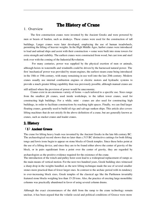
The History of Crane1. OverviewThe first construction cranes were invented by the Ancient Greeks and were powered by men or beasts of burden, such as donkeys. These cranes were used for the construction of tall buildings. Larger cranes were later developed, employing the use of human treadwheels, permitting the lifting of heavier weights. In the High Middle Ages, harbor cranes were introducedto load and unload ships and assist with their construction – some were built into stone towers for extra strength and stability. The earliest cranes were constructed from wood, but cast iron and steel took over with the coming of the Industrial Revolution.For many centuries, power was supplied by the physical exertion of men or animals, although hoists in watermills and windmills could be driven by the harnessed natural power. The first 'mechanical' power was provided by steam engines, the earliest steam crane being introducedin the 18th or 19th century, with many remaining in use well into the late 20th century. Modern cranes usually use internal combustion engines or electric motors and hydraulic systems to provide a much greater lifting capability than was previously possible, although manual cranes are still utilized where the provision of power would be uneconomic.Cranes exist in an enormous variety of forms – each tailored to a specific use. Sizes range from the smallest jib cranes, used inside workshops, to the tallest tower cranes, used for constructing high buildings. For a while, mini - cranes are also used for constructing high buildings, in order to facilitate constructions by reaching tight spaces. Finally, we can find larger floating cranes, generally used to build oil rigs and salvage sunken ships. This article also covers lifting machines that do not strictly fit the above definition of a crane, but are generally known as cranes, such as stacker cranes and loader cranes.2. History(1)Ancient GreeceThe crane for lifting heavy loads was invented by the Ancient Greeks in the late 6th century BC. The archaeological record shows that no later than c.515 BC distinctive cuttings for both lifting tongs and lewis irons begin to appear on stone blocks of Greek temples. Since these holes point at the use of a lifting device, and since they are to be found either above the center of gravity of the block, or in pairs equidistant from a point over the center of gravity, they are regarded by archaeologists as the positive evidence required for the existence of the crane.The introduction of the winch and pulley hoist soon lead to a widespread replacement of ramps as the main means of vertical motion. For the next two hundred years, Greek building sites witnesseda sharp drop in the weights handled, as the new lifting technique made the use of several smaller stones more practical than of fewer larger ones. In contrast to the archaic period with its tendencyto ever-increasing block sizes, Greek temples of the classical age like the Parthenon invariably featured stone blocks weighing less than 15-20 tons. Also, the practice of erecting large monolithic columns was practically abandoned in favor of using several column drums.Although the exact circumstances of the shift from the ramp to the crane technology remain unclear, it has been argued that the volatile social and political conditions of Greece were moresuitable to the employment of small, professional construction teams than of large bodies of unskilled labor, making the crane more preferable to the Greek polis than the more labor-intensive ramp which had been the norm in the autocratic societies of Egypt or Assyria.The first unequivocal literary evidence for the existence of the compound pulley system appears in the Mechanical Problems (Mech. 18, 853a32-853b13) attributed to Aristotle (384-322 BC), but perhaps composed at a slightly later date. Around the same time, block sizes at Greek temples began to match their archaic predecessors again, indicating that the more sophisticated compound pulley must have found its way to Greek construction sites by then.Ancient RomeThe heyday of the crane in ancient times came during the Roman Empire, when construction activity soared and buildings reached enormous dimensions. The Romans adopted the Greek crane and developed it further. We are relatively well informed about their lifting techniques, thanks to rather lengthy accounts by the engineers Vitruvius (De Architectura 10.2, 1-10) and Heron of Alexandria (Mechanica 3.2-5). There are also two surviving reliefs of Roman treadwheel cranes, with the Haterii tombstone from the late first century AD being particularly detailed.The simplest Roman crane, the Trispastos, consisted of a single-beam jib, a winch, a rope, and a block containing three pulleys. Having thus a mechanical advantage of 3:1, it has been calculated that a single man working the winch could raise 150 kg (3 pulleys x 50 kg = 150), assuming that 50 kg represent the maximum effort a man can exert over a longer time period. Heavier crane types featured five pulleys (Pentaspastos) or, in case of the largest one, a set of three by five pulleys (Polyspastos) and came with two, three or four masts, depending on the maximum load. The Polyspastos, when worked by four men at both sides of the winch, could already lift 3000 kg (3 ropes x 5 pulleys x 4 men x 50 kg = 3000 kg). In case the winch was replaced by a treadwheel, the maximum load even doubled to 6000 kg at only half the crew, since the treadwheel possesses a much bigger mechanical advantage due to its larger diameter. This meant that, in comparison to the construction of the Egyptian Pyramids, where about 50 men were needed to move a 2.5 ton stone block up the ramp (50 kg per person), the lifting capability of the Roman Polyspastos proved to be 60 times higher (3000 kg per person).However, numerous extant Roman buildings which feature much heavier stone blocks than those handled by the Polyspastos indicate that the overall lifting capability of the Romans went far beyond that of any single crane. At the temple of Jupiter at Baalbek, for instance, the architrave blocks weigh up to 60 tons each, and one corner cornice block even over 100 tons, all of them raised to a height of about 19 m. In Rome, the capital block of Trajan's Column weighs 53.3 tons, which had to be lifted to a height of about 34 m (see construction of Trajan's Column).It is assumed that Roman engineers lifted these extraordinary weights by two measures (see picture below for comparable Renaissance technique): First, as suggested by Heron, a lifting tower was set up, whose four masts were arranged in the shape of a quadrangle with parallel sides, not unlike a siege tower, but with the column in the middle of the structure (Mechanica 3.5). Second, a multitude of capstans were placed on the ground around the tower, for, although having a lower leverage ratio than treadwheels, capstans could be set up in higher numbers and run by more men (and, moreover, by draught animals). This use of multiple capstans is also described by AmmianusMarcellinus (17.4.15) in connection with the lifting of the Lateranense obelisk in the Circus Maximus (ca. 357 AD). The maximum lifting capability of a single capstan can be established by the number of lewis iron holes bored into the monolith. In case of the Baalbek architrave blocks, which weigh between 55 and 60 tons, eight extant holes suggest an allowance of 7.5 ton per lewis iron, that is per capstan. Lifting such heavy weights in a concerted action required a great amount of coordination between the work groups applying the force to the capstans.Middle AgesDuring the High Middle Ages, the treadwheel crane was reintroduced on a large scale after the technology had fallen into disuse in western Europe with the demise of the Western Roman Empire. The earliest reference to a treadwheel (magna rota) reappears in archival literature in France about 1225, followed by an illuminated depiction in a manuscript of probably also French origin dating to 1240. In navigation, the earliest uses of harbor cranes are documented for Utrecht in 1244, Antwerp in 1263, Brugge in 1288 and Hamburg in 1291, while in England the treadwheel is not recorded before 1331.Generally, vertical transport could be done more safely and inexpensively by cranes than by customary methods. Typical areas of application were harbors, mines, and, in particular, building sites where the treadwheel crane played a pivotal role in the construction of the lofty Gothic cathedrals. Nevertheless, both archival and pictorial sources of the time suggest that newly introduced machines like treadwheels or wheelbarrows did not completely replace more labor-intensive methods like ladders, hods and handbarrows. Rather, old and new machinery continued to coexist on medieval construction sites and harbors.Apart from treadwheels, medieval depictions also show cranes to be powered manually by windlasses with radiating spokes, cranks and by the 15th century also by windlasses shaped like a ship's wheel. To smooth out irregularities of impulse and get over 'dead-spots' in the lifting process flywheels are known to be in use as early as 1123.The exact process by which the treadwheel crane was reintroduced is not recorded, although its return to construction sites has undoubtedly to be viewed in close connection with the simultaneous rise of Gothic architecture. The reappearance of the treadwheel crane may have resulted from a technological development of the windlass from which the treadwheel structurally and mechanically evolved. Alternatively, the medieval treadwheel may represent a deliberate reinvention of its Roman counterpart drawn from Vitruvius' De architectura which was available in many monastic libraries. Its reintroduction may have been inspired, as well, by the observation of the labor-saving qualities of the waterwheel with which early treadwheels shared many structural similarities.Structure and placementThe medieval treadwheel was a large wooden wheel turning around a central shaft with a treadway wide enough for two workers walking side by side. While the earlier 'compass-arm' wheel had spokes directly driven into the central shaft, the more advanced 'clasp-arm' type featured arms arranged as chords to the wheel rim, giving the possibility of using a thinner shaft and providing thus a greater mechanical advantage.Contrary to a popularly held belief, cranes on medieval building sites were neither placed on the extremely lightweight scaffolding used at the time nor on the thin walls of the Gothic churches which were incapable of supporting the weight of both hoisting machine and load. Rather, cranes were placed in the initial stages of construction on the ground, often within the building. When a new floor was completed, and massive tie beams of the roof connected the walls, the crane was dismantled and reassembled on the roof beams from where it was moved from bay to bay during construction of the vaults. Thus, the crane ‘grew’ and ‘wandered’ with the building with the result that today all extant construction cranes in England are found in church towers above the vaulting and below the roof, where they remained after building construction for bringing material for repairs aloft.Less frequently, medieval illuminations also show cranes mounted on the outside of walls with the stand of the machine secured to putlogs.Mechanics and operationIn contrast to modern cranes, medieval cranes and hoists - much like their counterparts in Greece and Rome - were primarily capable of a vertical lift, and not used to move loads for a considerable distance horizontally as well. Accordingly, lifting work was organized at the workplace in a different way than today. In building construction, for example, it is assumed that the crane lifted the stone blocks either from the bottom directly into place, or from a place opposite the centre of the wall from where it could deliver the blocks for two teams working at each end of the wall. Additionally, the crane master who usually gave orders at the treadwheel workers from outside the crane was able to manipulate the movement laterally by a small rope attached to the load. Slewing cranes which allowed a rotation of the load and were thus particularly suited for dockside work appeared as early as 1340. While ashlar blocks were directly lifted by sling, lewis or devil's clamp (German Teufelskralle), other objects were placed before in containers like pallets, baskets, wooden boxes or barrels.It is noteworthy that medieval cranes rarely featured ratchets or brakes to forestall the load from running backward. This curious absence is explained by the high friction force exercised by medieval treadwheels which normally prevented the wheel from accelerating beyond control. Harbor usageAccording to the "present state of knowledge" unknown in antiquity, stationary harbor cranes are considered a new development of the Middle Ages. The typical harbor crane was a pivoting structure equipped with double treadwheels. These cranes were placed docksides for the loading and unloading of cargo where they replaced or complemented older lifting methods like see-saws, winches and yards.Two different types of harbor cranes can be identified with a varying geographical distribution: While gantry cranes which pivoted on a central vertical axle were commonly found at the Flemish and Dutch coastside, German sea and inland harbors typically featured tower cranes where the windlass and treadwheels were situated in a solid tower with only jib arm and roof rotating. Interestingly, dockside cranes were not adopted in the Mediterranean region and the highly developed Italian ports where authorities continued to rely on the more labor-intensive method ofunloading goods by ramps beyond the Middle Ages.Unlike construction cranes where the work speed was determined by the relatively slow progressof the masons, harbor cranes usually featured double treadwheels to speed up loading. The two treadwheels whose diameter is estimated to be 4 m or larger were attached to each side of the axle and rotated together. Today, according to one survey, fifteen treadwheel harbor cranes from pre-industrial times are still extant throughout Europe.[28] Beside these stationary cranes, floating cranes which could be flexibly deployed in the whole port basin came into use by the 14th century.RenaissanceA lifting tower similar to that of the ancient Romans was used to great effect by the Renaissance architect Domenico Fontana in 1586 to relocate the 361 t heavy Vatican obelisk in Rome. From his report, it becomes obvious that the coordination of the lift between the various pulling teams required a considerable amount of concentration and discipline, since, if the force was not applied evenly, the excessive stress on the ropes would make them rupture.Early modern ageCranes were used domestically in the 17th and 18th century. The chimney or fireplace crane was used to swing pots and kettles over the fire and the height was adjusted by a trammel.4. Types of the cranesMobileMain article: Mobile craneThe most basic type of mobile crane consists of a truss or telescopic boom mounted on a mobile platform - be it on road, rail or water.FixedExchanging mobility for the ability to carry greater loads and reach greater heights due to increased stability, these types of cranes are characterized that they, or at least their main structure does not move during the period of use. However, many can still be assembled and disassembled.外文翻译起重机的历史1. 概况第一台具有机械结构的起重机是由古希腊人发明的,并且由人或者是牲畜比如驴,作为动力源。
农业机械化及其自动化英语

农业机械化及其自动化英语
随着农业现代化的发展,农业机械化和自动化变得越来越重要。
下面是一些相关的英语词汇和短语。
1. Agriculture machinery - 农业机械
2. Tractor - 拖拉机
3. Harvester - 收割机
4. Seeder - 播种机
5. Irrigation system - 灌溉系统
6. Fertilizer spreader - 施肥机
7. Plow - 犁
8. Cultivator - 耕种机
9. Crop rotation - 种植轮作
10. Precision farming - 精准农业
11. Smart agriculture - 智能农业
12. Agricultural automation - 农业自动化
13. Agricultural robots - 农业机器人
14. GPS technology - 全球定位系统技术
15. Sensor technology - 传感器技术
16. Remote sensing - 遥感技术
17. Data analysis - 数据分析
以上词汇和短语可以帮助你更好地理解农业机械化及其自动化
的相关内容。
播种机的一般构造与工作原理

播种机的一般构造与工作原理1、引言播种机是农业现代化中的一种必备设备,它极大地提高了农业生产效率。
知道播种机的构造和工作原理对于农民和科技人员都有帮助。
2、播种机的一般构造播种机分为两个主要部分:播种部分和驱动部分。
播种部分主要包括种子箱、输种装置、种子挑选装置等,而驱动部分通常由轮轴、传动系统、机架等组成。
2.1种子箱种子箱是存储种子的地方,通常位于播种机的正前方。
种子箱的大小通常由农民根据实际需要进行选择。
2.2输种装置输种装置用于将种子从种子箱输送到种子挑选装置之中。
通常,这个过程是由电机和一系列输送带完成的。
2.3种子挑选装置种子挑选装置用于将种子按一定的规格进行挑选。
这个过程中,种子挑选器会筛选出大小和形状相似的种子。
2.4轮轴轮轴是播种机的驱动装置。
它的作用是将机器向前移动。
2.5传动系统传动系统是连接轮轴和电机的部分。
传动系统通常由皮带、齿轮和链条组成。
2.6机架机架是播种机的主体部件。
它是由灰铸铁或者钢板加强而成的,负责连接播种部分和驱动部分。
3、播种机的工作原理播种机的工作原理主要分为两个步骤:挑选种子和播种。
3.1种子挑选在播种之前,种子必须经过挑选。
通常,种子挑选是由一系列运转的轻微振动产生的。
通过振动,农民可以筛选出大小和形状相似的种子,并通过集中到种子挑选装置的筛子之中完成挑选。
3.2播种当种子通过挑选之后,它们将移动到输种装置之中,供播种使用。
通常,这个过程是由电机驱动的输送带完成的。
当种子到达播种位置时,农民按下一个光电控制开关启动播种。
在这个过程中,种子挑选装置会将已经挑选好的种子分配到排好的位置上。
一旦所有的种子都已经播种,播种机将自动停止。
4、总结播种机是农业生产中不能或缺的设备。
了解播种机的构造和工作原理有助于农民和科技人员更好地使用和改进播种机的性能。
这篇文章简要介绍了播种机的一般构造和工作原理,为读者进一步学习和了解相关知识提供了有价值的信息。
第五章播种机械施肥中耕机械简介

• (5)槽轮与排种盒的相对位置
• 防漏角1、2均不能大于种子的自然休止角;
而倾角应大于种子的自然休止角。 •
•2
PPT文档演模板
第五章播种机械施肥中耕机械简介
三、点播排种器简介
PPT文档演模板
第五章播种机械施肥中耕机械简介
•充种角
PPT文档演模板
第五章播种机械施肥中耕机械简介
•护种胶带
•驱动 轮
• •
• Grain drill
• Rowcrop planter
谷 物 条 播 机
•1、用于谷物条播 中 耕
•2、播行较窄、行距小 作
•3、苗期不机械中耕 物
•4、多采用整体式种箱 播
•5、各行排种器采用同 轴传动
种 机
•1、用于中耕作物条播 或点播
•2、可进行行间中耕 •3、行距大,播行少 •4、按行作成单体式 •5、各单体可随地面起
• 6)外槽轮排种器的有关参数
• (1)槽轮直径d 播麦类:d=40~50mm;
•
播大粒种子:d可大到110mm;
•
播小粒种子:d=24~28mm。
• (2)转速n n=9~60r/min
• 转速低,均匀性差;转速高,易伤种子。直径 小的槽轮可适当提高转速,减小脉动现象。
• (3)槽轮工作长度L L>1.5~2 倍种子长度
• 长度过小种子填充受阻,排种不均。一般在 30~50mm。
PPT文档演模板
第五章播种机械施肥中耕机械简介
• (4)凹槽形状和槽数Z
• 槽数太少,会减少带动层厚度,降低排种均匀 性;但太多,又容易损伤种子。通常Z=10~18。
•一般h为种子厚度的2~3倍;b为种子长度的2倍。
- 1、下载文档前请自行甄别文档内容的完整性,平台不提供额外的编辑、内容补充、找答案等附加服务。
- 2、"仅部分预览"的文档,不可在线预览部分如存在完整性等问题,可反馈申请退款(可完整预览的文档不适用该条件!)。
- 3、如文档侵犯您的权益,请联系客服反馈,我们会尽快为您处理(人工客服工作时间:9:00-18:30)。
黑龙江工程学院本科生毕业设计 1 附 录 Seeder history and introduction he first century B.C., China has good, this is to promote the use of the world's earliest drill machine, today is still in the north of equal applications. 1636 in Greece first Taiwan machine made. In 1830, russians in livestock HuaLi more on LiBo machine made. 1860 years later, the countries such as Britain and started mass production work grain suitable drill. After the 20 th century have appeared traction and hanging drill machine, and the use of grain strength of the machine. 50 s development precision machine. China from the 1950 s to introduce grain suitable drill, cotton machine, etc. 60 s has developed into a suspension type grain machine, centrifugal machine, universal frame and gas suction style such as machine machine DuoZhong type, and grinding lines to the development of the device. In the 70 s, has formed the seeding machine general machine and grain joint seeder two series, and has developed precision machine. Europe first Taiwan machine made in 1636 in Greece. In 1830, the russians in livestock HuaLi more on the sowing device LiBo machine made. Britain, the United States and other countries in 1860 years later started mass production work grain suitable drill. 20 centuries later period, there appeared the traction and hanging drill machine, and the use of grain strength of the machine. In 1958, Norway appear first Taiwan centrifugal machine, 50 s gradually developed all kinds of precision machine. China in the 1950 s introduced from abroad grain suitable drill, cotton machine, the '60 s and has successfully developed suspension type grain machine, centrifugal machine, universal frame and gas suction style such as machine machine DuoZhong models, and has developed grinding lines of the device. In the 70 s, has formed the seeding machine general machine and grain joint seeder two series and production. For grain and intertillage crops, grasses, and all kinds of vegetables with suitable drill and XueBo machine are already widely used. At the same time, also has developed DuoZhong precision machine. Corn is uniform, sowing machine depth is consistent, stable, cover earth good row 黑龙江工程学院本科生毕业设计 2 spacing, save seeds, work efficiency higher characteristic. The correct use of machine should pay attention to the following points: master 10 1 in the maintenance of the field before operation to clean up the trash and sowing the device on the open ditch the winding grass, clay, ensure good condition, and the tractors and the transmission, the rotation of the machine parts, according to the requirements of the manual filling lubricating oil, especially every time before operation should pay attention to the transmission chain lubrication and a tight situation on the fastening bolts and sowing. 2 frame can't tilt seeder and tractors to hook up may not be tilt, work should make frame a state level before and after. 3 do well adjusted according to the instructions of the rules and regulations of the main requirements, the rate, open ditch is the spaced, open ditch crackdown on the depth of the wheel turns the soil suitable. 4 attention and good seed to join the seeds of seeds, where there is no box small, Bi, miscellaneous, to ensure the effectiveness of the seeds; Second seed box with kind of quantity of at least to add to that cover the box of entrance, in order to ensure the smooth. 5 test broadcasts to ensure the quality of the large area, seeded before sowing, must hold to test broadcasts 20 meters, observe the machine work. Please agricultural technology personnel, local farmers consultation, testing confirmed that meet local agricultural demands, and then carry on large area sown. 6 note of uniform linear driving NongJiShou choose the assignment walking routes, should guarantee and kind of and mechanical in and out of convenience, planting time to pay attention to more uniformly and in a straight line, line, not fast and slow or stop the leak, lest the replay, broadcast; To prevent the open ditch jams, the rise and fall of machine to are on the march, when turning back or operation should be filed seeder. 7 was the first out first broadcast to rolling out, out, was hard by deep too shallow. 8 often observed planting time constant observation of the device, open ditch device, the cover and transmission's work, such as the clogging, clay, winding grass, seed cover lax, shall be ruled out in time. Adjustment, repair, lubrication or cleaning the winding grass, etc, must be in after parking. 9 protect parts of the machine work, it is strictly prohibited to scale back or sharp turn and the ascension of the machine should slow or land, lest attaint parts. 10 note seed box when the seeds of the homework seed shall be not less than 1/5 of the