主动控制悬架系统外文原文
汽车系统构造英文版-Lesson14SuspensionSystem资料
• Most automotive vehicles have independent front suspension, usually using coil springs as part of either a short-arm long-arm or a MacPherson-strut suspension system. A MacPherson-strut suspension (see illustration) combines a coil spring and shock absorber into a strut assembly that requires only a beam-type lower control arm.
• Some vehicles with short-arm long-arm front suspension use either longitudinal or transverse torsion bars for the front springs. One end of the torsion bar is attached to the lower control arm, and the other end is anchored to the vehicle body or frame. As the tire and wheel move up and down, the torsion bar provides springing action by twisting about its long axis.
Lesson 14 Suspension System
• Suspension is the term given to the system of springs, shock absorbers and linkages that connects a vehicle to its wheels. Suspension systems serve a dual purpose – contributing to the car's roadholding/handling and braking for good active safety and driving pleasure, and keeping vehicle occupants comfortable and reasonably well isolated from road noise, bumps, and vibratinsion systems of most vehicles in current production make use of coil springs. Two lower control arms, which are connected to the frame and rear axle housing, keep the housing from shifting too far toward the front or rear. A pair of upper control arms (torque arms) also connect the frame and rear axle housing. The upper and lower control arms prevent the differential and rear axle housing from rotating.
汽车维修英语
AAA——American Automobile Association——美国汽车协会;美国汽车联合会AAAA——澳大利亚汽车后市场协会AAAV——远征战斗车辆(现在称EFV)AAC——数字音频解码技术AAC——辅助空气控制阀AANH——美国网络销售公司AAP——Auto Aftermarket Parts——汽车售后部件AAS——Adaptive Air Suspension——可调空气悬架(奥迪);主动式悬架AASS——Adaptive Air Suspension System——可调空气悬架系统(奥迪)AAT——Adaptive Airbage Technology——(德尔福)自适应安全气囊技术AB——All Balanced——全面均衡(设计理念)(简称AB设计理念,该理念主要包括动力、空间、安全、操控和个性化5个方面)ABA——制动摩擦片虚位自动调校补偿系统ABC——Active Body Control——主动车身控制;动态车身控制;主动车身控制悬架系统ABC+T——Automatic Brake and Traction Control——自动制动控制+牵引力辅助控制ABD——自动制动差速器;差速制动系统ABD——英国驾车者协会ABI——英国保险联合会ABS——Anti-lock Brake System或Anti-lock Braking System——防抱死制动系统说明:没有ABS时,汽车紧急制动时,4个车轮会被完全抱死,这时只要有轻微的侧向力作用(比如倾斜的路面或者地上的一块小石头),汽车就会发生侧滑、甩尾,甚至完全调头。
特别是在弯道上行驶时,由于前轮抱死,汽车将因车轮缺乏附着而丧失转向能力,沿着惯性方向向前直至停止。
ABS的功能就在于通过控制制动油压的收放,达到对车轮抱死的控制。
ABS系统可以使汽车在任何工况下对汽车的4个车轮通过4个独立的传感器进行检测,并对各个车轮独立控制,使4个车轮均处于最佳的制动状态,能够保障汽车在任何的路面上,特别是在雨水路面和冰雪路面上制动时,保证汽车的任何一个车轮都不抱死,避免汽车发生侧滑、甩尾及无法转向等,从而使汽车具有良好的的制动效能、稳定性和转向性,提高汽车的制动安全性。
汽车中英文对照表(带详细解释)

汽车中英文对照表AAA——American Automobile Association——美国汽车协会;美国汽车联合会AAAA——澳大利亚汽车后市场协会AAC——数字音频解码技术AAC——辅助空气控制阀AANH——美国网络销售公司AAP——Auto Aftermarket Parts——汽车售后部件AAS——Adaptive Air Suspension——可调空气悬架(奥迪);主动式悬架AASS——Adaptive Air Suspension System——可调空气悬架系统(奥迪)AA T——Adaptive Airbage Technology——(德尔福)自适应安全气囊技术AB——All Balanced——全面均衡(设计理念)(简称AB设计理念,该理念主要包括动力、空间、安全、操控和个性化5个方面)ABA——制动摩擦片虚位自动调校补偿系统ABC——Active Body Control——主动车身控制;动态车身控制;主动车身控制悬架系统ABC+T——Automatic Brake and Traction Control——自动制动控制+牵引力辅助控制ABD——自动制动差速器;差速制动系统ABD——英国驾车者协会ABI——英国保险联合会ABS——Anti-lock Brake System或Anti-lock Braking System——防抱死制动系统说明:没有ABS时,汽车紧急制动时,4个车轮会被完全抱死,这时只要有轻微的侧向力作用(比如倾斜的路面或者地上的一块小石头),汽车就会发生侧滑、甩尾,甚至完全调头。
特别是在弯道上行驶时,由于前轮抱死,汽车将因车轮缺乏附着而丧失转向能力,沿着惯性方向向前直至停止。
ABS的功能就在于通过控制制动油压的收放,达到对车轮抱死的控制。
ABS系统可以使汽车在任何工况下对汽车的4个车轮通过4个独立的传感器进行检测,并对各个车轮独立控制,使4个车轮均处于最佳的制动状态,能够保障汽车在任何的路面上,特别是在雨水路面和冰雪路面上制动时,保证汽车的任何一个车轮都不抱死,避免汽车发生侧滑、甩尾及无法转向等,从而使汽车具有良好的的制动效能、稳定性和转向性,提高汽车的制动安全性。
吉林大学半主动悬架研究及控制系统设计

4
第一章 绪论
因为它控制算法比较复杂 所需控制器成本高 而且 要求的执行元件精度高 响应快等等 这一些都决定了它的难实用性
2
第一章 绪论
表 1-1 国外汽车公司选装的电控悬架以及汽车品牌 汽车公司名称 汽 车 名 称 电控悬架名称 主动控制悬架 电子控制悬架
丰田汽车公司
日产汽车公司 三菱汽车公司 富士重工 福特汽车公司 VOLVO 汽车公 司 奔驰汽车公司
Soarer 4.0GT 规格车 Lexus C 规格(F Package 装 用车 世纪牌轿车 E 型 L 型 凌志牌轿车 B 规格 Plezo TEMS Soarer 轿车 2.5GT 双增压 Plezo TEMS 阿 利 斯 特 轿 车 3.0V(Plezo TEMS 短 跑 家 Treno 轿 车 GT APEX 塞普它轿车 3.0G 及 2.0G 小星牌轿车 GT 总统牌轿车 全车 英菲尼迪 Q45 轿车 V 型 公爵牌绞车 Brougham VIP 荣光牌轿车 Brougham VIP 快乐牌轿车 Exceed 系列 列西加牌厢式车 兰鸟牌轿车 兰夫人牌轿车 VOLVO740 轿车 奔驰牌轿车
半主动悬架控制器硬件设计 微处理器模块 传感器输入模块 输出驱动模块 硬件电路的抗干扰技术 半主动悬架控制器软件设计 设计原则 软件开发 内容小节
§4.2
一 二
§4.3 §5.1
一 二 三
第五章 半主动悬架系统的试验研究
半主动悬架系统可调减振器的试验研究 试验目的以及试验设备 试验安排以及步骤 减振器的台架试验结果 控制器软件的仿真调试及硬件的在线仿真 试验目的以及试验设备 试验步骤 仿真结果 内容小结
目录
目
第一章 绪论 §1.1 §1.2
主动悬架系统

主动悬架系统主动悬架是用一个有自身能源的力发生器来代替被动悬架中的弹簧和减振器。
根据作动器响应带宽的不同,主动悬架又分为宽带主动悬架和有限带宽主动悬架,也被叫做全主动悬架和慢主动悬架。
全主动悬架系统所采用的作动器具有较宽的响应频带,以便对车轮的高频共振也加以控制。
作动器多采用电液或液气伺服系统,控制带宽一般应至少覆盖0〜15Hz,有的作动器响应带宽甚至高达100Hz。
结构示意图见上图。
从减少能量消耗的角度考虑,也可保留一个与作动器并联的传统弹簧,以用来支持车身静载。
主动悬架的一个重要特点就是,它要求作动器所产生的力能够很好地跟踪任何力控制信号。
因此,它为控制律的选择提供了一个广泛的设计空间,即如何确定控制律以使系统能够让车辆达到最佳的总体性能。
近二十年来,有大量关于主动悬架的研究论文及专题回顾文献发表。
研究结果表明,主动悬架能够在不同路面情况及行驶条件下显著地提高车辆性能。
主动悬架的研制工作起始于八十年代。
Lotus 制造了第一辆装有主动悬架的样车。
其系统的响应可达30Hz,它可使乘坐舒适性和转弯及制动时的车身姿态控制提高约35%还有一些主动悬架实施的例子,如Lotus Turbo Esprit 、Damlar Benz的试验样机系统、BMW和Ford等。
然而,由于这些主动悬架系统具有的高成本、高能耗、增加的重量及复杂程度,使主动悬架仅限于样车及一些赛车等有限的应用上。
结构上,有限带宽主动悬架通常由作动器与一个普通弹簧串联后,再与一个被动阻尼器并联构成,见上图。
这种系统在低频时(一般小于5 或6 赫兹)采用主动控制,而高于这个频率时,控制阀不再响应,系统特性相当于传统的被动悬架,而被动悬架在高频时的效果也比较好。
由于有限带宽主动悬架作动器仅需在一窄带频率范围内工作,所以它降低了系统的成本及复杂程度,比全主动悬架便宜得多。
尽管如此,它的主动控制仍然覆盖了主要的车身振动,包括纵向、俯仰、侧倾以及转向控制等要求的频率范围,改善了车身共振频率附近的行驶性能,提高了对车身姿态的控制,性能可达到与全主动系统很接近的程度。
电控悬架系统的结构控制原理与检修-(毕业论文)
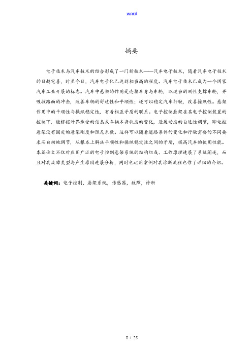
摘要电子技术与汽车技术的结合形成了一门新技术——汽车电子技术,随着汽车电子技术的日趋完善,时至今日,汽车电子化已达到相当高的程度。
汽车电子技术已成为一个国家汽车工业开展的标志。
汽车中悬架的作用是连接车身与车轮, 以适当的刚性支撑车轮, 并吸收路面的冲击, 改善车辆的舒适性和平顺性; 还可以稳定汽车行驶, 改善操纵性。
悬架作用中的平顺性与操纵稳定性, 有着相互矛盾的联系。
电子控制悬架在其电子控制装置的控制下, 能根据外界承受的信息或车辆本身状态的变化, 进展动态的自适性调节, 即电控悬架没有固定的悬架刚度和阻尼系数。
这样可以随着道路条件的变化和行驶需要的不同要求而自动地调节, 从根本上解决平顺性和操纵稳定性之间的矛盾, 提高汽车的使用性能。
本篇论文不仅对应用广泛的电子控制悬架系统的结构组成、工作原理进展了系统阐述,而且对其故障类型与产生原因进展分析,同时也运用案例对其诊断流程也作了详细的介绍。
关键词:电子控制,悬架系统,传感器,故障,诊断AbstractElectronic technology and the technique of car formed a new technology, automobile electronic technology, with the improvement of automobile electronic technology, today, the automobile electronic has reached quite high degree. Automobile electronic technology has bee a symbol of the national auto industry development. Automobile suspension is the function of connection in the body and wheels, with proper rigidity supporting wheels, and absorb the impact of the pavement, improve the vehicle fort peace obey; Also can stable the car, improve handling. Suspension effect of ride fort and handling stability, have conflicting links. Electronic control suspension under the control of electronic control devices, can according to the outside world to accept the information or the change of the state of the vehicle itself, which can adjust the dynamic adaptive sex, namely electronic control suspension has no fixed suspension stiffness and damping coefficient. As the change of road conditions and driving with the requirement of the need to automatically adjust, fundamentally solve the contradiction between ride fort and handling stability, improve the use performance of the car. This paper not only to the wide application of electronic control suspension system structure, working principle of the system is expounded, and the fault type and the causes were analyzed, and also use case also has made the detailed introduction of the diagnosis processKeywords: electronic control, suspension system, sensor, fault, diagnosis目录摘要IAbstractII1 电子控制悬架系统概述61.1 电子控制悬架系统的背景和意义61.2 电子控制悬架系统国内外的研究方向61.3 电子控制悬架系统的种类71.4 电子控制悬架系统的结构和工作原理71.5 电子控制悬架系统的主要功能82 电子控制悬架系统传感器92.1 车身高度传感器92.2 方向盘转角传感器92.3 车速传感器102.4 加速信号112.5 车门信号112.6 制动信号112.7 悬架控制开关123 电子控制悬架系统的电子控制模块133.1 电控空气悬架系统电子控制模块〔悬架ECU〕功能133.2 电控空气悬架系统电子控制模块〔悬架ECU〕的结构和工作原理133.3 电控空气悬架系统执行器的工作原理与其功用143.4 电控空气悬架系统执行器的分类154 电子控制悬架系统故障诊断与排除164.1 电子控制悬架系统故障诊断164.2 故障类型与原因164.3 故障诊断方法174.4 电控悬架系统故障诊断的案例分析19 总结与展望21致谢22参考文献241 电子控制悬架系统概述汽车悬架的作用是缓冲和吸收来自车轮的振动,在汽车行驶过程中还要传递车轮与路面间产生的驱动力和制动力。
汽车主动悬架系统及其控制方法
汽车主动悬架系统及其控制方法汽车乘坐舒适性和操作安全性与汽车主动悬架关系紧密,主动悬架研究及其重要。
本文介绍了主动悬架的工作原理以及主动悬架的控制方法:天棚阻尼控制、最优控制、自适应控制、滑模变结构控制、模糊控制、神经网络控制等。
预测了主动悬架系统的发展和未来趋势。
标签:主动悬架;控制方法;汽车被动悬架通常由具有确定参数的弹性元件和阻尼元件等构成,对于路面的适应性能较差,对汽车改善舒适性等方面不利。
在被动悬架设计的过程中,往往不能使乘客的乘坐舒适性与车辆的操纵稳定性同时达到最优。
在很大程度上及一些因素的影响,我国的汽车很少采用主动悬架,因为在主动及半主动悬架研究方面,我国相对来说比较落后,就技术层面来讲,主动悬架相对于被动悬架在控制方面较为复杂,研究起来比较困难,对其进一步发展产生了阻碍。
1 汽车主动悬架的工作原理汽车主动悬架可以根据路面的实时状况来进行调节,相比于被动悬架其可以调节该悬架的刚度及阻尼,使悬架找到一个最优的状态来满足舒适性及操纵稳定性。
它是在被动悬架的基础上改进而来,增加用来控制调节力的装置,通过控制系统对传遞来的一系列信号进行反馈调节力的大小进而使悬架刚度及阻尼发生变化来使乘坐舒适性及操纵稳定性同时达到最优。
2 主动悬架系统的控制方法主动悬架的控制方法有很多种,在不同的控制方法中所运用的学科知识也不相同,涉及到多种理论的分析研究。
但是,各种控制方法均有自身的独特之处,对几种主动悬架的控制方法介绍如下。
2.1 天棚阻尼器控制天棚阻尼器控制的主要方法是通过一种对力的控制来实现其功能。
该力是由主动悬架发生并且需要与该车的车体的速度成正比例关系,由于在该系统中相比其他系统多了一个固定一端的阻尼器,来作为参考,这就是天棚阻尼控制系统的大致原理和名称由来。
在该控制方法中,控制力的大小是由车体的速度传递到到力传感器的大小决定的,传感器数量不多且结构也不算复杂,更不需要多学科的交叉研究,比较容易实现其功能且使用起来相对快速。
车辆半主动悬架控制研究论文
摘要悬架系统是汽车实现操纵稳定性和乘坐舒适性的重要机械结构。
车辆悬架系统性能的优劣直接影响车辆的乘坐舒适性和操纵安全性。
传统的被动悬架系统设计参数一旦优化确定后就无法动态改变,难以使汽车具有良好的平顺性。
由弹性元件和阻尼可调减振器组成的半主动悬架有耗能少,易实现等优点,可以改善汽车行驶的平顺性和操作稳定性。
半主动悬架既克服了被动悬架系统的缺陷,又使实现成本降低,成为汽车技术中的研究热点之一。
本文以汽车半主动悬架系统为研究对象,在对悬架的性能进行分析的基础上,建立了的二自由度1/4的汽车半主动悬架的数学模型。
同时,考虑到路面扰动输入对悬架控制的重要影响,建立积分白噪声形式的路面不平度数学模型。
在此基础上,提出了适用于半主动悬架系统的模糊逻辑控制,以控制输出信号动态改变可调阻尼器的阻尼系数从而达到自适应减振控制的目的。
最后采用我国常见的C级路面作为激励信号,根据前面所建立的数学模型,利用Matlab/Simulink建立了动态模型,并进行计算机仿真,与被动悬架就簧载质量加速度、轮胎动载荷、悬架动挠度这些性能指标进行了对比分析。
通过仿真表明,模糊控制较大的改善了半主动悬架系统的性能,比传统的被动悬架具有更好的减振性能,能够明显地改善舒适性。
关键词:半主动悬架,模糊控制,仿真分析,MATLABIAbstractSuspension is the important part of vehicle,it can improve ride comfort and handling steadiness.The dynamic Performance of susPension system directly influences ride comfort and handling of driving vehicles. It is very difficult for the traditional passive suspension whose parameters have been fixed by optimization to adjust them to improve on the ride comfort. Semi-active suspension,composed of controllable spring and damper element,consumes little energy and is easy to design and manufacture.And then semi-active suspension can also improve ride comfort and handling steadiness.Not only the semi- active suspension can perform the function of active suspension system,but the requirements of the power is very few,So it has been a hot topic in the research field of cars.The article studies the automobile semi-active suspension.Based on analyzing the performances,the text uses the two freedoms 1/4 suspension model. .Considering the influence of the input disturbance,a mathematical description of road surface irregularity is established,which is the model of integral white noise. On the basis of the above study, A fuzzy logic control method for semi-active suspension is putforward to control the output signal and adjust the damper coeffieient in order to adaptively absorb the shock and improve the ride comfort.Then the software Matlab/Simulinkis used to simulate the semi-active suspension controlled by the above-mentioned fuzzy control method on B level typical road. The performances of bodywork acceleration , the tire load and suspension displacemen are analyzing between the semi-active suspension and the passive suspension.Acording to the simulation results,compared with the passive suspension control,semi-active suspention fuzzy control which obviously improve ride comfort and handling steadiness could reduce the bodywork acceleration , the tire load and suspension displacement in a large degree.Key words: Semi-active suspention, Fuzzy control, Simulation analysis, MATLABII目录摘要 (I)ABSTRACT ................................................................................................................. I I 目录 ......................................................................................................................... I II 第一章引言 .................................................................................................... - 1 -1.1车辆悬架系统发展概述 (1)1.2半主动悬架的控制方法 (3)1.3课题的研究意义 (5)1.4论文的主要研究工作 (5)1.5本章小结 (6)第二章车辆半主动悬架系统的分析与建模 .................................................... - 7 -2.11/4车二自由度悬架模型 . (7)2.1.1被动悬架模型 ........................................................................................ - 7 -2.1.2半主动悬架模型 ...................................................................................... - 8 -2.2路面输入模型. (9)2.2.1路面不平度的功率谱 .............................................................................. - 9 -2.2.2空间频率谱函数与时间频率谱函数的转化 ........................................ - 11 -2.2.3积分白噪声随机路面轮廓 .................................................................... - 12 -2.3本章小结. (13)第三章半主动悬架系统的模糊控制 .............................................................. - 14 -3.1模糊逻辑系统概述 (14)3.2理想天棚阻尼控制策略 (14)3.3模糊控制器的设计 (16)3.3.1半主动悬架模糊控制器的基本结构及设计流程 ................................ - 16 -3.3.2定义系统的输入、输出变量及模糊化 ................................................ - 17 -3.3.3隶属函数的确定 .................................................................................... - 17 -III3.3.4模糊控制规则的选取 ............................................................................ - 19 -3.3.5模糊逻辑推理 ........................................................................................ - 22 -3.3.6清晰化 .................................................................................................... - 22 -3.4本章小结. (23)第四章半主动悬架系统的仿真分析 .............................................................. - 24 -4.1MATLAB/S IMULINK仿真平台的介绍 (24)4.2系统仿真参数的取值 (25)4.3仿真结构图 (25)4.3.1积分白噪声激励路面输入Simulink模型............................................ - 25 -4.3.2被动悬架Simulink模型........................................................................ - 26 -4.3.3半主动悬架Simulink模型.................................................................... - 27 -4.3.4天棚阻尼控制二自由度车辆悬架Simulink模型................................ - 27 -4.3.5模糊控制下的半主动悬架Simulink模型............................................ - 28 -4.4悬架系统仿真分析 (29)4.4.1悬架系统的车身加速度仿真分析 ........................................................ - 29 -4.4.2悬架系统的动行程仿真分析 ................................................................ - 29 -4.4.3悬架系统的动载荷仿真分析 ................................................................ - 30 -4.5本章小结. (34)第五章总结与展望 .......................................................................................... - 35 -5.1总结 .. (35)5.2后续工作的展望 (35)参考文献 ................................................................................................................ - 37 -致谢 .................................................................................................................... - 40 -IV第一章引言1.1车辆悬架系统发展概述悬架是现代汽车上的重要总成之一,它是车架(或承载式车身)与车桥(或车轮)之间的一切传力装置的总称。
浅析汽车底盘主动悬架控制方法
浅析汽车底盘主动悬架控制方法汽车底盘主动悬架是一种先进的车辆控制技术,通过传感器和控制模块实时监测车辆行驶状态和路况,控制悬架系统调整车身姿态和车轮垂直力分布,为车辆提供更优秀的悬架性能和更舒适的驾乘体验。
下面,就汽车底盘主动悬架控制方法进行浅析。
1. 悬架系统结构:汽车底盘主动悬架系统主要由传感器、控制模块、执行机构和电源等组成,其中传感器用于实时采集车辆姿态信息、路况信息和车速信息等,控制模块通过算法处理这些数据,并输出控制信号给执行机构进行悬架调整,例如液压阀门的调整,提高或降低车辆在弯道通过时的侧倾角。
2. 悬架系统控制策略:汽车底盘主动悬架系统有不同的控制策略,例如主动防侧滑控制(Active Roll Control,ARC)、自适应悬挂(Adaptive Suspension)和自适应空气悬挂(Adaptive Air Suspension)等。
主动防侧滑控制是控制车身侧倾角的主要方式,它基于车身加速度和弯道半径等参数,以最大程度降低车辆侧倾角为目标,通过液压元件对玻璃架进行调节,实现车身侧倾角的抑制。
自适应悬挂是根据驾驶员驾驶行为调整悬架硬度和舒适性的方法。
它能够通过调节悬挂硬度来适应路况和驾乘条件,保持车辆的稳定性和驾驶舒适性,减少驾驶员和乘员的颠簸和振动。
自适应空气悬挂是一种基于汽车启动状态和重量分布,实现对悬挂硬度和车身高度的自动调整。
这种悬挂系统可以通过增加或减少气泡的压力来调整车身高度,并根据载荷或驾驶员偏好等因素,调整悬挂硬度,改善驾乘体验。
3. 悬架控制算法:汽车底盘主动悬架的控制算法是实现上述控制策略的关键。
最常用的算法是火花点火虚拟传感器(Spark Ignition Virtual Sensor,SIVS)和模型参考迭代控制(Model Reference Iterative Control,MRIC)。
SIVS算法可以通过收集发动机和车辆其他传感器的数据,建立虚拟模型来实现和优化悬架控制策略。
- 1、下载文档前请自行甄别文档内容的完整性,平台不提供额外的编辑、内容补充、找答案等附加服务。
- 2、"仅部分预览"的文档,不可在线预览部分如存在完整性等问题,可反馈申请退款(可完整预览的文档不适用该条件!)。
- 3、如文档侵犯您的权益,请联系客服反馈,我们会尽快为您处理(人工客服工作时间:9:00-18:30)。
SIMULATION BASED DESIGN FOR ACTIVELYCONTROLLED SUSPENSION SYSTEMSJoseph H. Beno, University of Texas Center for ElectromechanicsDamon A. Weeks, University of Texas Center for ElectromechanicsJason R. Mock, University of Texas Center for ElectromechanicsAbstractActive and semi-active suspension systems are mechatronic systems that require a disciplined approach to synergistically combine the traditional engineering fields of mechanical, electronic, controls, power, systems, automotive, and suspension.Integrating suspension design is particularly challenging because it strongly interfaces with safety issues and driver perceptions, which are not easily optimized. Since 1993, the University of Texas Center for Electromechanics (UT-CEM) has successfully developed high performance active suspension technology and systems for a wide range of military vehicles, including small tactical trucks (e.g., HMMWV), medium tactical trucks (e.g., LMTV), and hybrid electric tanks (e.g., BAE’s Lancer prototype). In addition to developing active suspension technology, UT-CEM has developed, refined, and validated an integrated simulation based design approach for controlled suspension systems that is the topic of this paper.Modeling EnvironmentUT-CEM’s desi gn approach is centered on the MATLAB-Simulink environment, coupled with a dynamic vehicle simulation platform, such as DADS or ADAMS. The controls are modeled in Simulink, with full inclusion of all sensor processing/filtering, in a manner that allows direct transition to intended vehicle platform through autocode generation. Consequently, simulated control systems are identical to vehicle platform control systems. Over time, this improves simulation accuracy, expands usefulness of simulation results in the design and specification process, and allows relatively successful tuning and debugging prior to vehicle integration. The approach also tracks power and energy flow, allowing full understanding of trade-offs between component characteristics and power consumption in the design process. An example of the benefits of this tool was an early realization that active suspension control objectives directly impact power consumption and that active suspension systems can be designed to consume less vehicle power than passive dampers for vigorous off-road terrain (a concept that has been verified in recent HMMWV active suspension system durability testing).The basic modeling environment is shown below. This environment allows a medium fidelity model that runs quickly. In this particular example, our active suspension system demonstration on a hybrid electric 22 Ton tank is depicted. Vehicle dynamics are captured in DADS, a vehicle dynamic modeling environment (alternative environments, such as ADAMS, are also suitable). The objective of the model is to provide early estimates of suspension performance; provide a platform to develop optimal component specifications (e.g., active suspension actuator force, speed, and bandwidth capabilities based on performance goals); and to develop/tune the suspension control system.The interface between the Simulink and DADS model provides a natural separation between software and hardware that is eventually deployed on the vehicle.The mechanical system is primarily captured in the vehicle model, while the control software is conveniently segregated in the Simulink model. Output from the DADS model can represent information that can be physically sensed locally (i.e., on the vehicle, such as accelerometer output) and/or global variables that cannot be locally sensed on the vehicle (such as inertial velocity or direction of travel). Since one objective of the simulation is to develop the actual control system that is to be deployed on the vehicle, care is taken to ensure that only true sensor data is fed to the suspension controller. Global states are only fed to the simulated Vehicle Control Unit where it can be used to conveniently control vehicle speed and direction. The suspension controller contains all suspension control algorithms, all sensor filtering modules, and all other interfaces necessary for final vehicle implementation. The DADS vehicle model includes actual vehicle and suspension component dimension and mass properties, including suspension actuators and sensor locations. Of particular importance, in between the Simulink controller model and the DADS vehicle model, there is a sample and hold block (labeled Control Cycle Time on above figure) to properly enforce controller cycle time – actuator force commands are a held for a complete controller cycle time (typically 1-2 milliseconds) to enforce reality.Model ValidationModel validation is a continuing activity. During the early design phase of a new suspension application, previous validated models are exploited to generate reliable simulation results. Typically, at this stage in the design process, identified trends are reliable and absolute numbers are within ~ 10-15%. Consequently, trade studies to evaluate design parameters like actuator force/power specifications vs. performance (e.g., driver average absorbed power on a particular test terrain) are dependable within ~10-15%.After component hardware is built, detailed characterization results are used to refine models and performance estimates. The figure below shows a configurable single wheel test rig at UT-CEM, designed to replicate a single wheel station of a vehicle (in the example shown below, it was an 6x6 unmanned hybrid electric wheeled vehicle that employed skid steering and traction control). This test rig is also supported by test rigs (not shown) that isolate actuators to perform detailed actuator characterization. Component design refinements can be identified as a result of this coupled characterization-simulation activity with a high degree of confidence.After the full compliment of hardware is fabricated and integrated on a vehicle, simple vehicle tests are used to further refine the simulation. Since actuator characterization has been completed, these on vehicle tests are particularly useful in identifying vehicle characteristics such as leaf-spring damping that were only estimated in previous design stages. As an example, the figure below shows actuator force (vertical axis) vs. actuator displacement (horizontal axis) on the front left wheel station of an Army LMTV (2.5 ton, leaf-spring, cargo truck), when a 0.3 Hz sinusoid actuator force is simultaneously applied to all four vehicle wheel stations. The step changes at the right and left edges of the plots are related to total suspension friction. Since theactuators are well characterized, adjusting vehicle friction characteristics until simulation matches test data, results in a reasonably good estimate of vehicle dynamic friction characteristics. It is noted, however, that these friction tests are performed at relatively slow suspension travel speeds, whereas high speed travel on vigorous off-road terrain results in high suspension travel speeds, a limitation in this method of estimated vehicle suspension characteristics.With the previous model verification steps complete, full vehicle tests on harsh off-road terrain can provide additional model validation. The plots below compare test and simulation results on the UT-CEM 2 inch rms test track for the LMTV vehicle described above. For this validation exercise it is important that accurate terrain displacement information is input into the simulation. It is also important that test drivers maintain accurate vehicle speed because vehicle response to dynamic terrain is highly depend on speed. Of course, drivers are less perfect than simulations in this respect, resulting in differences between simulated and actual test data. The left plot shows suspension travel for the left front wheel station as a function of time for this terrain. Note that the simulated and test data are in very close agreement. There is a minor difference in time location of some travel peaks, indicating differences between test and simulated vehicle speeds as a function of time. Additionally, there are some minor differences in the magnitude of some peaks, although agreement is generally excellent. Some of the differences are due to speed variations between the model and actual vehicle, some are likely due to inaccuracies in suspension friction models, and some are due to tire parameters. The right plot compares average driver absorbed power for the LMTV on the UT-CEM 2 inch rms test track. Since the absorbed power metric is a time average, the value changes over time as additional data is included in the average. Driver average absorbed power is a processed (filtered) result from an accelerometer at the driver’s seat and is highly dependant on minor changes in vehicle speeds. The right plot compares the simulation with four different tests. The tests indicate a spread, with one test (20 mph-1) looking different than the others (highlighting the sensitivity of the average absorbed power result). Note that simulation results compare well with actual data, somewhere in the middle of the various test runs.Software Transition from Simulation to Vehicle Developing active suspension controls in the simulation environment described above greatly facilitates transition to the final vehicle using the dSpace product. dSpace offers an autocode generation product customized for Simulink and controller hardware suitable for prototype testing. Various products exist to continue this autocode transition process to controller hardware suitable for production vehicles. Consequently, discipline in developing the initial control algorithms in simulation (e.g., only using realizable sensor input in the simulation) greatly facilities successful transition. Our experience has shown that control gains tuned in simulation serve as very good initial set points during vehicle debugging and tuning. In the end, driver sensation guides final tuningparameter selection.Conclusion and ObservationsThe simulation tools and processes described above have proven highly effective in seven different active suspension demonstration programs, ranging form HMMWV’s to tracked vehicles, and also in transition to production ready systems. Over this time, a few keys to success have emerged:• Use every new application to continually upgrade/improve simulation tools.• Remain focused on model validation.• Friction remains the largest model uncertainty; continually improve friction models at every opportunity. • Enforce discipline in control algorithm simulation to facilitate transition to prototype and production vehicles systems.。