ML1 - D8 Week
用于摇瓶高密度培养的自诱导培养基
12/20/07 Recipes and stock solutions described in Protein Expression and Purification 41: 207-234 (2005)Protein Production by Auto-Induction in High-Density Shaking CulturesF. William StudierBiology Department, Brookhaven National Laboratory, Upton, NY 11973studier@Abstract. Inducible expression systems in which T7 RNA polymerase transcribescoding sequences cloned under control of a T7lac promoter efficiently produce a wide variety ofproteins in Escherichia coli. Investigation of factors that affect stability, growth and induction ofT7 expression strains in shaking vessels led to the recognition that sporadic, unintendedinduction of expression in complex media, previously reported by others, is almost certainlycaused by small amounts of lactose. Glucose prevents induction by lactose by well-studiedmechanisms. Amino acids also inhibit induction by lactose during log-phase growth, and highrates of aeration inhibit induction at low lactose concentrations. These observations, andmetabolic balancing of pH, allowed development of reliable non-inducing and auto-inducingmedia in which batch cultures grow to high densities. Expression strains grown to saturation innon-inducing media retain plasmids and remain fully viable for weeks in the refrigerator, makingit easy to prepare many freezer stocks in parallel and use working stocks for an extended period.Auto-induction allows efficient screening of many clones in parallel for expression andsolubility, as cultures have only to be inoculated and grown to saturation, and yields of targetprotein are typically several-fold higher than obtained by conventional IPTG induction. Auto-inducing media have been developed for labeling proteins with selenomethionine, 15N or 13C,and for production of target proteins by arabinose induction of T7 RNA polymerase from thepBAD promoter in BL21-AI. Selenomethionine labeling was equally efficient in the commonlyused methionine auxotroph B834(DE3) (found to be metE) or the prototroph BL21(DE3).overview 2-5GeneralNon-inducing agar plates and stabs for expression strains 6Non-inducing media currently used routinely for growing stocks 7Auto-inducing media currently used routinely 8Media with arabinose for auto-induction from T7lac in BL21-AI 812,9,14minimalmediaAuto-inducingMedium for rapid growth of high-density cultures to prepare plasmids 9Auto-inducing media for labeling with SeMet 10Auto-inducing media for labeling with 15N and 13C 11Low-phosphate (25 mM) non-inducing and auto-inducing media 12High-phosphate (100 mM) non-inducing and auto-inducing media 13-14solutions 15-20StockGrowth media have been developed to control the expression of target genes in E. coli strains such as BL21(DE3), in which T7 RNA polymerase expressed from the inducible lacUV5 promoter in the chromosome directs the expression of target protein from the T7lac promoter in multi-copy pET expression vectors (Studier et al., Methods in Enzymology 185: 60-89 (1990)). These media should also be applicable to other strains where expression is controlled by promoters inducible by lactose or IPTG. Media are also described for auto-induction of promoters inducible by arabinose.Non-inducing media. Fully defined non-inducing media give reliable growth without detectable induction of target protein all the way to saturation. They also support growth to higher cell densities than typical of complex media such as LB (10 g tryptone, 5 g yeast extract, 5 g NaCl per liter) and produce cultures that remain highly viable for weeks in the refrigerator. Even strains expressing target proteins highly toxic to the host remained stable in these non-inducing media, grew sub-cultures with little lag and were fully competent to express target protein. In contrast, unintended spontaneous induction can occur in typical complex media (Grossman et al., Gene 209: 95-103 (1998)), which can stress or kill productive cells and favor poorly expressing derivatives. The common practice of using cultures grown to saturation in LB or other complex media to produce seed cultures for production of target protein may be responsible for many cases of poor expression in IPTG-inducible expression systems. Although addition of glucose can prevent such induction, finding a glucose concentration that reliably prevents induction in complex media without cultures becoming very acidic at saturation proved difficult or impossible.Unintended induction is almost certainly due to small amounts of lactose present in enzymatic digests of casein, such as tryptone or N-Z-amine, in commonly used media such as LB. Casein comes from milk, which contains lactose, and different lots of purified casein used to make growth media may well contain different levels of residual lactose. The high concentrations of amino acids in such media suppress induction by lactose during log-phase growth, but less than 0.001% lactose can cause induction upon approach to saturation in cultures grown at moderate levels of aeration. Such inducing activity appears to be relatively common in commercial growth media made from enzymatic digests of casein. Therefore, isolation of expression strains, growth of freezer stocks for long-term storage, and growth of seed stocks for protein production should all be done in reliable non-inducing media such as MDG or MDAG.Auto-inducing media. Media such as ZYM-5052 and MDA-5052 have been formulated to grow IPTG-inducible expression strains, initially without induction, and then to induce production of target protein automatically, usually near saturation at high cell density. A limited concentration of glucose is metabolized preferentially during growth, which prevents uptake of lactose until the glucose is depleted, usually in mid to late log phase. As the glucose is depleted, lactose can be taken up and converted by β-galactosidase to the inducer allolactose. Allolactose causes release of lac repressor from its specific binding sites in the DNA and thereby induces expression of T7 RNA polymerase from the lacUV5 promoter and unblocks T7lac promoters, allowing expression of target proteins by T7 RNA polymerase. Depletable glucose can also allow auto-induction of arabinose-inducible promoters by arabinose in the medium, and the method could also be applied to promoters regulated by other metabolites subject to catabolite repression or inducer exclusion. Even strains that produce target proteins highly toxic to the host cell can grow normally and express their protein by auto-induction. Strains defective in lacZ(β-galactosidase) or lacY (lactose permease) are not likely to be suitable for auto-induction by lactose because they will be unable to import lactose or convert it to allolactose.Lactose itself is not a particularly good carbon and energy source to support continued target protein production after auto-induction, because production of target protein competes so successfully for resources that proteins of the lactose operon may not accumulate to levels that provide efficient use of lactose. Glycerol is a good carbon and energy source that does not interfere with induction and allows growth to much higher culture densities. As with glucose, metabolism of glycerol generates acid, but very high densities of auto-induced cultures can be achieved with sufficient aeration and maintenance of a pH near neutral.Growth conditions. Reasonably good aeration is important for maintaining pH near neutral and obtaining growth to high culture densities. We typically grow cultures in an incubator shaker at 20°C or 37°C and 300-350 rpm, using vessels and volumes of culture that give approximately equivalent levels of aeration. For auto-induction of many cultures in parallel to test expression and solubility, we grow 0.5 ml of culture in 13x100 mm glass culture tubes. Usually only a few microliters of such cultures is sufficient for all needed analyses by gel electrophoresis. Up to 2.5 ml of culture in non-inducing media is grown in 18x150 mm glass culture tubes to make freezer stocks, plasmid preps or seed stocks for moderate-scale auto-induction, although 1.5 ml is probably preferable. Seed stocks for larger-scale auto-induction can be grown in Erlenmeyer flasks, the culture occupying approximately 5-10 % of the flask volume. Moderate-scale auto-induction can use 400-500 ml of culture in 1.8-liter baffled Fernbach flasks (Bellco).Trace metals. Growth to high density in fully defined media requires the addition of trace metals. A concentration of 0.2x trace metals (recipe for 1000x stock solution on page 19) is sufficient but, if a mixture of trace metals is not available, 100 µM FeCl3 will increase saturation density about as well. Growth in media containing ZY has not been limited by lack of trace metals but, given the variability of complex media components, it seems prudent to add 0.2x trace metals, if available. For target proteins of unknown metal content, 1x trace metals provides nine different metals in amounts sufficient to saturate substantial production of target protein, and 5x can be tolerated with little effect on growth. Individual metals can be supplied for production of target proteins known to bind specific metals. Trace metal mix at 1x concentration or FeCl3 at concentrations higher than about 10 µM tend to precipitate slowly in growth media. Such precipitation does not seem to inhibit growth but might decrease availability to metal-binding target proteins. The presence of 1 mM citrate seems to reduce or prevent such precipitation.Additives. Fully defined media must be appropriately supplemented for growth of strains with nutritional requirements: at least 150 µg/ml of methionine is needed to support growth ofB834(DE3) to saturation in MDG , and 1 µM thiamine (vitamin B1) is 10-fold more than needed to support high-density growth of XL1Blue-MR, an F-recA1 strain we use as an initial recipient for expression plasmids. I also found that growth of cultures in most batches of complex media such as LB, 2xYT or terrific broth is limited by lack of magnesium. Simply adding 2 mM MgSO4 typically increased saturation densities by 50% to 5-fold.Kanamycin resistance. Although BL21(DE3) is unable to grow in LB containing as little as 10 µg of kanamycin per ml, it grows well even at ten-fold higher levels of kanamycin in the comparably rich auto-inducing medium ZYP-5052, which contains 100 mM phosphate. However, kanamycin at 100 µg/ml does prevent growth in media reformulated to contain only 50 mM phosphate (or less), such as the auto-inducing medium ZYM-5052 we use currently.Freezer stocks for long-term storage of expression strains are made by adding 0.1 ml of 100% w/v (80% v/v) glycerol to 1 ml of culture that was grown to saturation in a non-inducing medium such as MDG or MDAG-135, mixing well and placing in a -70°C freezer. Reasonably well aerated cultures in MDG or MDAG at 37°C typically saturate at an OD600 around 7-10. Working stocks are grown from freezer stocks by scraping up a small amount of frozen culture with a sterile plastic pipettor tip and inoculating non-inducing medium. The stability, viability and reliability of protein expression from cultures grown in non-inducing media makes it possible to work with many strains in parallel. Re-transformation or streaking out cultures to obtain a "fresh" single colony each time a protein is to be produced, an unfortunate and tedious practice in some labs, is not necessary for reliable expression of target protein.Auto-induction works well over the entire range of temperatures suitable for growth. Auto-inducing cultures are typically inoculated with one-thousandth volume of an MDG or MDAG seed culture and grown to saturation overnight at 37°C. In general, increasing the rate of aeration increases the density at which the culture auto-induces and saturates, and also increases the minimum concentration of lactose needed for good auto-induction. Routine auto-inducing media contain 0.2% lactose, a concentration chosen to be well in excess of that needed for good auto-induction over the range of conditions we use.Cultures grown at 20°C usually auto-induce and saturate at higher culture densities at than at 37°C (probably due to the higher solubility of oxygen at lower temperature). Higher saturation densities combined with slower growth at low temperature means that cultures may become quite dense after overnight incubation but may not yet be induced, so care must be taken not to collect low-temperature cultures before they have saturated. The time needed for auto-induction at low temperatures can be shortened by incubating a few hours at 37°C, until cultures become lightly turbid (probably OD600 less than 1), and then transferring to the lower temperature.Incubation for several hours at saturation after auto-induction usually has little effect on accumulation or solubility of target protein. Auto-induced cultures typically saturate at an OD600 around 7-10 at 37°C under the conditions we use but can reach 20-30 in favorable cases. Culture densities greater than OD600 ~50 have been attained by using higher concentrations of glycerol, metabolic balancing of pH with aspartate or succinate, and higher levels of aeration. Auto-inducing media should be capable of producing even higher densities in batch culture in fermenters, where high levels of aeration can be maintained for large culture volumes. When the target protein is sufficiently toxic to the host, expression of even small amounts as auto-induction begins may prevent much further increase in density, and such cultures may not achieve densities much higher than OD600 of 1-2. Because the OD600 is due to light scattering rather than absorption, an accurate reading requires dilution of the culture (in water) to a concentration that gives a reading between about 0.030 and 0.200, typically a 100-fold dilution.Parallel growth of many non-induced or auto-induced cultures is feasible because cultures are simply inoculated and grown to saturation. This is a great convenience and simplifies manual or automated induction and analysis of multiple clones compared to conventional IPTG induction, which requires monitoring growth of each culture and adding inducer at the proper stage of growth. Others have been successful using these recipes in the multi-well plates commonly used in automated systems, but it was important to keep volumes low enough that reasonably good mixing and aeration was obtained.Stock solutions were designed for convenience and flexibility in assembling different media, and to avoid combining components that are incompatible upon autoclaving. Media are usually assembled from autoclaved or filter-sterilized stock solutions immediately before use, but most appear to be stable for extended periods in the refrigerator if contamination by mold spores is avoided. Stock solutions are stored at room temperature, except as noted in the recipes.Fully defined, non-inducing media we currently use routinely: pages 6-7MDAG-11 is a fully defined, non-inducing medium for agar plates and stabs to select, titer and distribute expression strains, and for liquid suspension of colonies to be retained temporarily as standing cultures at room temperature when purifying strains. MDG and MDAG-135 are fully defined, non-inducing media for growing shaking cultures of expression strains for freezer stocks, working stocks (which remain highly viable for weeks in the refrigerator), and for preparing plasmids from BL21(DE3) or other host strains susceptible to unintended induction.Cultures that grow slowly because they are stressed by basal expression of a highly toxic target protein should be grown in MDAG-135 rather than MDG. Such cultures are likely to contain a mixture of newly-divided growing cells that have not yet produced a transcript of the toxic gene and cells that are dead or dying because they have produced a burst of toxic target protein, perhaps as little as that generated from a single transcript. The faster rate of division in MDAG-135 should increase the fraction live cells in the population and may allow the production of cultures where essentially all of the live cells are capable of producing target protein rather than consisting primarily of poorly expressing mutants that have overgrown the culture.Auto-inducing media we currently use routinely: page 8ZYM-5052 is a complex auto-inducing medium and MDA-5052 is a fully defined auto-inducing medium, both of which can support growth to relatively high densities and produce substantial amounts of a wide range of target proteins. Addition of arabinose to ZYM-5052 or MDA-5052 at a final concentration of 0.05% produces media for auto-induction of target genes in BL21-AI (Invitrogen), where production of T7 RNA polymerase is under control of the pBAD promoter and the target gene is expressed from the T7lac promoter.Complex medium we currently use for rapid growth of high-density cultures: page 9ZYM-505 is a complex medium that produces dense cultures of commonly used lab strains, satisfies complex nutritional requirements, and is useful for rapid growth of high-density cultures for preparing plasmids. The possibility of unintended induction may make ZYM-505 poorly suited for growing some expression strains.Auto-inducing media for labeling target proteins with SeMet, 15N or 13C: pages 10-11Low-phosphate (25 mM) non-inducing and auto-inducing minimal media: page 12High-phosphate (100 mM) non-inducing and auto-inducing media used earlier: page 13-14Stock solutions: pages 15-20Non-inducing medium for agar plates and soft agar stabsMDAG-11 plates (50 mM phosphate) non-inducing minimal medium +aaMDAG-11 plates plus appropriate antibiotic(s) and any requirednutritional supplement(s) are used to isolate transformants and to titer cells carrying expression plasmids. Colonies grow almost as well onfully defined MDAG-11 plates as on TBY plates, and at least some strains that express proteins toxic to the host make colonies on MDAG-11 but not on TBY plates. Stabs in MDAG soft agar (0.7%) are used for distributing expression strains.To make 500 ml of 1% agar (~20 ml per plate yields ~25 plates)5 g agar~475 ml H2Oautoclave 15 min, mix well, let cool ~10 min on benchAddcompositionFinal1 ml 1 M MgSO4 25Na2HPO4mM100 µl 1000x metals 25 mM KH2PO41.25 ml 40% glucose 50 mM NH4Cl2 ml 25% aspartate 5 mM Na2SO410 ml 50xM 2 mM MgSO414 ml 18aa (7.14 mg/ml each) 0.2x metals = 10 µM Fe + 90.1% glucose = 5.6 mM=mM7.50.1%aspartate200µg/ml each of 18 aa (no C,Y) Add other required nutrients or selective antibioticsMix well, pour ~20 ml per plate (slowly pouring into each standard plate usually gives about the right amount per plate)MDAG-11+B1+K plates (for routine use with kanamycin-resistant strains) This recipe contains thiamine (B1), required for growth of XL1Blue-MR, and kanamycin for selection of expression plasmids. B1 is not needed by BL21(DE3).Follow above MDAG-11 recipe; add the following after autoclavingthe agar and before mixing to pour the platesAddcompositionFinal50 µl 10 mM thiamine (B1) 1 µM thiamine (B1)2 ml kanamycin (25 mg/ml) 100 µg/ml kanamycinNon-inducing media used routinely for isolating expression strains and growing freezer stocks and seed cultures for auto-induction MDAG-11 (50 mM phosphate) non-inducing for suspending colonies, dilutionTo make 10 mlFinal composition9.43 ml H 2O25 mM Na 2HPO 4 20 µl 1M MgSO 4 25 mM KH 2PO 42 µl 1000x metals 50 mM NH 4Cl25 µl 40% glucose 5 mM Na 2SO 440 µl 25% aspartate 2 mM MgSO 4200 µl 50xM 0.2x metals = 10 µM Fe + 9 280 µl 18aa (7.14 mg/ml each) 0.1% glucose = 5.6 mM0.1% aspartate = 7.5 mM200 µg/ml each of 18aa (no C,Y)MDG (50 mM phosphate) non-inducing minimal medium for shaking culturesTo make 10 mlFinal composition9.55 ml H 2O25 mM Na 2HPO 4 20 µl 1M MgSO 4 25 mM KH 2PO 42 µl 1000x metals 50 mM NH 4Cl125 µl 40% glucose 5 mM Na 2SO 4100 µl 25% aspartate 2 mM MgSO 4200 µl 50xM 0.2x metals = 10 µM Fe + 9 0.5% glucose = 27.8 mM0.25% aspartate = 18.8 mMMDAG-135 (50 mM phosphate) non-inducing minimal +aa for shaking culturesTo make 10 mlFinal composition9.37 ml H 2O25 mM Na 2HPO 4 20 µl 1M MgSO 4 25 mM KH 2PO 42 µl 1000x metals 50 mM NH 4Cl87.5 µl 40% glucose 5 mM Na 2SO 440 µl 25% aspartate 2 mM MgSO 4200 µl 50xM 0.2x metals = 10 µM Fe + 9 280 µl 18aa(7.14 mg/ml each) 0.35% glucose = 19.4 mM0.1% aspartate = 7.5 mM200 µg/ml each of 18aa (no C,Y)Optional additions (per 10 ml):1 µl 10 mM thiamine (B1) 1 µM thiamine (B1)40 µl kanamycin (25 mg/ml) 100 µg/ml kanamycinAuto-inducing media currently used routinelyZYM-5052 (50 mM phosphate) auto-inducing complex mediumTo make 10 mlFinal composition9.57 ml ZY 1 % N-Z-amine AS20 µl 1M MgSO 4 0.5% yeast extract2 µl 1000x metals (optional) 25 mM Na 2HPO 4200 µl 50x5052 25 mM KH 2PO 4200 µl 50xM 50 mM NH 4Cl5 mM Na 2SO 42 mM MgSO4 0.2x metals (optional) 0.5% glycerol = 54 mM 0.05% glucose = 2.8 mM0.2% α-lactose = 5.6 mM MDA-5052 ( 50 mM phosphate) auto-inducing minimal medium +aaRecipe differs from that given in the publication and previous handouts; it contains 0.1% aspartate instead of 0.25%, for better control of pHTo make 10 mlFinal composition9.26 ml H 2O25 mM Na 2HPO 4 20 µl 1M MgSO 4 25 mM KH 2PO 42 µl 1000x metals 50 mM NH 4Cl200 µl 50x5052 5 mM Na 2SO 440 µl 25% aspartate 2 mM MgSO 4200 µl 50xM 0.2x metals = 10 µM Fe + 9 280 µl 18aa (7.14 mg/ml each) 0.5 % glycerol = 54 mM0.05% glucose = 2.8 mM0.2 % α-lactose = 5.6 mM0.1% aspartate = 18.8 mM200 µg/ml each of 18aa (no C,Y)Optional additions (per 10 ml):1 µl 10 mM thiamine (B1) 1 µM B140 µl kanamycin (25 mg/ml) 100 µg/ml kanamycin20 µl 1000x metals 1x metals = 50 µM Fe + 9individual metal salts for known metal-binding target proteinsMedia with arabinose for auto-induction from T7lac in BL21-AIAdd arabinose to the any of the auto-inducing media to give afinal concentration of 0.05% arabinoseAuto-inducing minimal mediumMD-5052 (50 mM phosphate) auto-inducing minimal mediumTo make 10 mlFinal composition9.48 ml H 2O25 mM Na 2HPO 4 20 µl 1M MgSO 4 25 mM KH 2PO 42 µl 1000x metals 50 mM NH 4Cl200 µl 50x5052 5 mM Na 2SO 4100 µl 25% aspartate 2 mM MgSO 4200 µl 50xM 0.2x metals = 10 µM Fe + 9 0.5 % glycerol = 54 mM0.05% glucose = 2.8 mM0.2 % α-lactose = 5.6 mM0.25% aspartate = 18.8 mMComplex medium for rapid growth of high-density culturesZYM-505 (50 mM phosphate) complex medium, possible unintended inductionThis medium is used for rapid growth of high-density cultures forpreparing plasmids from strains that do not supply T7 RNA polymerase, and sometimes for growing strains that express innocuous targetproteins. However, the possibility of unintended induction may make this medium poorly suited for growing some expression strains,particularly those in which the target protein may stress the host. Plasmids from T7 expression strains are usually isolated from cultures grown on fully defined non-inducing media such as MDG or MDAG.To make 10 mlFinal composition 9.68 ml ZY 1 % N-Z-amine AS20 µl 1M MgSO 4 0.5%yeast extract 2 µl 1000x metals (optional) 25 mM Na 2HPO 4100 µl 100x505 25 mM KH 2PO 4200 µl 50xM 50 mM NH 4Cl5 mM Na 2SO 42 mM MgSO 40.2x metals (optional) 0.5% glycerol = 54 mM 0.05% glucose = 2.8 mMadd appropriate selective antibiotic(s)Auto-inducing medium for labeling with SeMetGreater than 90% replacement of methionines by SeMet in target proteins auto-induced in this medium was found whether using the prototroph BL21(DE3) or the methionine auxotroph, B834 (metE),apparently because the presence of Met/SeMet in the medium represses the methionine-synthesis pathway. Yields of SeMet-labeled target protein in PASM-5052 have been comparable to yields obtained by auto-induction in the absence of SeMet. In PASM-5052, unlabeled methionine at 10 µg/ml facilitates growth and auto-induction in 125 µg/ml of SeMet, which would otherwise be too toxic to allow high-density growth and auto-induction. Vitamin B12 stimulates the E. coli metH enzyme to catalyze regenerationof SeMet from the selenohomocysteine generated in methylation reactions. Growth at 37°C from a thousand-fold dilution typically reachessaturation in 14-16 hr. Growth at 20°C is much slower and a culture can take 3 days or longer to become induced and reach saturation. PASM-5052 contains 100 mM phosphate and was based on PA-5052 (page 14) before development of lower phosphate auto-inducing media; it could presumably be reformulated as MDASM-5052, containing 50 mM total phosphate and 0.1% aspartate, based on MDA-5052 (page 8).PASM-5052 (100 mM phosphate) auto-inducing minimal medium +aa To make 10 mlcompositionFinal9.01 ml H2O 50mMNa2HPO4KH2PO420 µl 1M MgSO4 50mM2 µl 1000x metals 25 mM (NH4)2SO4200 µl 50x5052 2 mM MgSO4500 µl 20xP 0.2x metals = 10 µM Fe + 9 200 µl 17aa(10 mg/ml each) 0.5 % glycerol = 54 mM4 µl Met (25 mg/ml) 0.05% glucose = 2.8 mM50 µl SeMet (25 mg/ml) 0.2 % α-lactose = 5.6 mM10 µl 100 µM vitamin B12 200 µg/ml each of 17aa (no C,Y,M)10 µg/ml Metµg/ml SeMet125vitaminB12nM100To make 800 ml725 ml H2O1.6 ml 1M MgSO4160 µl 1000x metals16 ml 50x505240 ml 20xP16 ml 17aa(10 mg/ml each)320 µl Met (25 mg/ml)100 mg bottle of SeMet800 µl 100 µM vitamin B12Auto-inducing minimal media for labeling with 15N and 13CTarget proteins may be labeled in auto-inducing media in which the sole nitrogen source is 15NH4Cl (LS-5052, page 12, or N-5052, below) or (15NH4)2SO4 (P-5052, page 14). The 50 mM 15NH4 in these media supports growth to high density, and high levels of expression make efficient use of the label. Reducing ammonium concentration below ~25 mM may significantly limit target protein expression in these media.N-5052 (100 mM phosphate) auto-inducing minimal medium for 15N labelingcompositionFinal50 mM Na2HPO450 mM KH2PO450 mM 15NH4Cl5 mM Na2SO42 mM MgSO40.2x metals = 10 µM Fe + 90.5 % glycerol = 54 mM0.05% glucose = 2.8 mM0.2 % α-lactose = 5.6 mMTarget proteins may be labeled with 13C-glycerol by auto-induction in C-750501 medium. The glycerol concentration has been increased to0.75% and the lactose concentration decreased to 0.01% to minimize the flow of carbon from lactose into target protein (glucose is depleted before target protein is induced). The 0.01% lactose will give good induction if aeration is not too high. This medium is an initial formulation aiming for maximum incorporation, and a systematic analysis may find that satisfactory labeling can be achieved at lower concentrations of 13C-glycerol, higher concentrations of lactose and higher rates of aeration. The small amount of glucose could also be labeled with 13C relatively inexpensively.C-750501(100 mM phosphate) auto-inducing minimal medium for 13C labelingcompositionFinal50 mM Na2HPO450 mM KH2PO450 mM NH4Cl5 mM Na2SO42 mM MgSO40.2x metals = 10 µM Fe + 90.75 % 13C-glycerol = 81 mM0.05% glucose = 2.8 mM0.01 % α-lactose = 0.28 mM。
欧司朗LED详解

LW W5AMGolden DRAGON PlusLead (Pb) Free Product - RoHS Compliant Released2011-07-291Besondere Merkmale•Gehäusetyp: weißes SMD Gehäuse, klare Silikonlinse, Chip level conversion•Typischer Lichtstrom: 100 lm bei 350 mA und bis zu 240 lm bei 1 A•Besonderheit des Bauteils: hocheffiziente Lichtquelle bei geringem Platzbedarf •Farbort: x = 0,33, y = 0,33 nach CIE 1931 (weiß)•typische Farbtemperatur: 5600 K •Farbwiedergabeindex: 80•Abstrahlwinkel: 170°•Technologie: ThinGaN•optischer Wirkungsgrad: 130 lm/W bei 100 mA•Gruppierungsparameter: Lichtstrom, Farbort •Verarbeitungsmethode: für SMT-Bestücktechniken geeignet •Lötmethode: Reflow Löten•Vorbehandlung: nach JEDEC Level 2•Gurtung: 24-mm Gurt mit 200/Rolle, ø180 mm oder 1200/Rolle, ø330 mm (auf Anfrage)•ESD-Festigkeit: ESD-sicher bis 8 kV nach JESD22-A114-D•Erweiterte Korrosionsfestigkeit: Details siehe Seite 11Anwendungen•Hinterleuchtung (Werbebeleuchtung, Allgemeinbeleuchtung)•Leselampen•Ersatz von Kleinst-Glühlampen•Fassadenbeleuchtung im Innen- und Außenbereich•Dekorative Beleuchtung •StraßenbeleuchtungFeatures•package: white SMD package, clear silicone lens, chip level conversion•typical Luminous Flux: 100 lm at 350 mA and up to 240 lm at 1 A•feature of the device: high efficient lightsource at low space•color coordinates: x = 0.33, y = 0.33 acc. to CIE 1931 (white)•typ. color temperature: 5600 K •color reproduction index: 80•viewing angle: 170°•technology: ThinGaN•optical efficiency: 130 lm/W at 100 mA •grouping parameter: luminous flux, color coordinates•assembly methods: suitable for SMT assembly methods•soldering methods: reflow soldering •preconditioning: acc. to JEDEC Level 2•taping: 24 mm tape with 200/reel, ø180 mm or 1200/reel, ø330 mm (on request)•ESD-withstand voltage: up to 8 kV acc. to JESD22-A114-D•Superior Corrosion Robustness: details see page 11Applications•backlighting (illuminated advertising, general lighting)•reading lamps•substitution of micro incandescent lamps•indoor and outdoor commercial and residential architectural lighting•decorative and entertainment lighting •street lighting2011-07-292Anm.:Die oben genannten Typbezeichnungen umfassen die bestellbaren Selektionen. Diese bestehen aus wenigenHelligkeitsgruppen (siehe Seite 6 für nähere Informationen). Es wird nur eine einzige Helligkeitsgruppe pro Gurt geliefert. Z.B.: LW W5AM -KXLX-5K8L bedeutet, dass auf dem Gurt nur eine der Helligkeitsgruppen KX, KY, KZ oder LX enthalten ist.Um die Liefersicherheit zu gewährleisten, können einzelne Helligkeitsgruppen nicht bestellt werden.Gleiches gilt für die Farben, bei denen Farbortgruppen gemessen und gruppiert werden. Pro Gurt wird nur eine Farbortgruppe geliefert. Z.B.: LW W5AM-KXLX -5K8L bedeutet, dass auf dem Gurt nur eine der Farbortgruppen -5K bis -8L enthalten ist (siehe Seite 5 für nähere Information).Um die Liefersicherheit zu gewährleisten, können einzelne Farbortgruppen nicht bestellt werden.Note:The above Type Numbers represent the order groups which include only a few brightness groups (see page 6for explanation). Only one group will be shipped on each reel (there will be no mixing of two groups on each reel). E.g. LW W5AM -KXLX-5K8L means that only one group KX, KY, KZ or LX will be shippable for any one reel.In order to ensure availability, single brightness groups will not be orderable.In a similar manner for colors where chromaticity coordinate groups are measured and binned, single chromaticity coordinate groups will be shipped on any one reel. E.g. LW W5AM-KXLX -5K8L means that only 1 chromaticity coordinate group -5K to -8L will be shippable on each reel (see page 5 for explanation). In order to ensure availability, single chromaticity coordinate groups will not be orderable.Bestellinformation Ordering Information TypTypeEmissions- farbeColor of EmissionLichtstrom 1) Seite 19Luminous Flux 1) page 19I F = 350 mA ΦV (mlm)Lichtstärke 2) Seite 19LuminousIntensity 2) page 19I F = 350 mA I V (mcd)BestellnummerOrdering CodeLW W5AM-KXLX-5K8L LW W5AM-KYLX-6K7Lwhite71.000 ... 130.000 82.000 ... 130.00025.100 (typ.) 26.500 (typ.)Q65110A9850 Q65110A95292011-07-293Maximum Ratings Bezeichnung ParameterSymbol SymbolWert Value Einheit Unit BetriebstemperaturOperating temperature range T op – 40 … + 125°C LagertemperaturStorage temperature range T stg – 40 … + 125°C Sperrschichttemperatur Junction temperatureT j135°C Sperrschichttemperatur für Kurzzeitanwendungen* Junction temperature for short term application*T j 175*°C Durchlassstrom (min.) Forward current (max.) (T S =25°C)I F I F1001000mA mA Stoßstrom Surge currentt ≤ 10 µs, D = 0.005, T S =25°C I FM2500mASperrspannung Reverse voltage (T S =25°C)V Rnot designed for reverse operationV *Auch bei höchsten Temperaturen zeigt der LED Chip sehr gute Leistungsmerkmale, aber es kann eine leichte Verfärbung des Gehäuses auftreten. Die mittlere Lebensdauer bei T j = 175°C beträgt 100h.*The LED chip exhibits excellent performance but slight package discoloration occurs at highest temperatures. Exemplary median lifetime for T j = 175°C is 100h.2011-07-294Characteristics (T S = 25 °C)Bezeichnung ParameterSymbol Symbol Wert Value Einheit Unit Farbkoordinate x nach CIE 19313) Seite 19(typ.)Chromaticity coordinate x acc. to CIE 19313) page 19I F = 350 mAx0.33–Farbkoordinate y nach CIE 19313) Seite 19(typ.)Chromaticity coordinate y acc. to CIE 19313) page 19I F = 350 mAy 0.33–Abstrahlwinkel bei 50 % ΙV (Vollwinkel)(typ.) Viewing angle at 50 % ΙV 2ϕ170Grad deg.Durchlassspannung 4) Seite 19)(min.) Forward voltage 4) page 19(typ.) I F = 350 mA (max.)V F V F V F2.73.23.7V V VSperrstromReverse current (max.)I Rnot designed for reverse operation µAWärmewiderstand Thermal resistance Sperrschicht/Lötpad (typ.) Junction/soldering point(max.)R th JS R th JS6.511*K/W K/W*R th (max) basiert auf statistischen Werten R th (max) is based on statistic values2011-07-295Farbortgruppen 5) Seite 195) page 19Gruppe Group Cx Cy Gruppe Group Cx Cy 5K0.2960.2597K0.3300.3100.2910.2680.3300.3300.3100.2970.3380.3420.3130.2840.3520.3445L 0.2910.2687L0.3300.3300.2850.2790.3300.3470.3070.3120.3470.3710.3100.2970.3450.3526K 0.3130.2848K0.3520.3440.3100.2970.3380.3420.3300.3300.3640.3800.3300.3100.3600.3576L 0.3100.2978L0.3450.3520.3070.3120.3470.3710.3300.3470.3670.4010.3300.3300.3640.3802011-07-296Gruppenbezeichnung auf Etikett Group Name on Label Beispiel: KX-5K Example: KX-5K Helligkeits-Gruppierungsschema Brightness Groups Helligkeitsgruppe Brightness Group Lichtstrom 1) Seite 19Luminous Flux 1) page 19 ΦV (mlm)Lichtstärke 2) Seite 19Luminous Intensity 2) page 19 I V (mcd)KX KY KZ LX71.000 ...82.000 82.000 ...97.000 97.000 ...112.000 112.000 ...130.00019.100 (typ.) 22.400 (typ.) 26.100 (typ.) 30.250 (typ.)Anm.:Die Standardlieferform von Serientypen beinhaltet eine Familiengruppe. Diese besteht auswenigen Helligkeitsgruppen. Einzelne Helligkeitsgruppen sind nicht bestellbar.Note:The standard shipping format for serial types includes a family group of only a few individualbrightness groups. Individual brightness groups cannot be ordered.Helligkeitsgruppe Brightness Group FarbortgruppeChromaticity Coordinate Group KX5KAnm.:In einer Verpackungseinheit / Gurt ist immer nur eine Helligkeitsgruppe enthalten.Note:No packing unit / tape ever contains more than one brightness group.2011-07-297Relative spektrale Emission 2) Seite 19 Relative Spectral Emission 2) page 19V(λ) = spektrale Augenempfindlichkeit / Standard eye response curve Φrel =Radiation Characteristic 2) page 19 Ιrel = f (ϕ); T S = 25 °C2011-07-298Durchlassstrom 2)4) Seite 19 Forward Current 2)4) page 19 I F = f (V F ); T S = 25 °Csolid line: specified DC-rangeRelative Farbortverschiebung 2) Seite 17Relative Chromaticity Coordinate Shift 2) page 17 ∆x, ∆y = f (I); T = 25 °CRelative Lichtstrom 2) Seite 19Relative Luminous Flux 2) page 19 ΦV /ΦV (350 mA) = f (I F ); T S = 25 °C2011-07-299Relative Vorwärtsspannung 2)4) Seite 19 Relative Forward Voltage 2)4) page 19∆V= V - V (25 °C) = f (T ); I = 350 mARelative Farbortverschiebung 2) Seite 19Relative Chromaticity Coordinate Shift 2) page 19 ∆x, ∆y = f (T); I F = 350 mA Relative Lichtstrom 2) Seite 19Relative Luminous Flux 2) page 19 ΦV /ΦV (25 °C) = f (T); I = 350 mA2011-07-2910Maximal zulässiger Durchlassstrom Max. Permissible Forward Current I FZulässige Impulsbelastbarkeit I F = f (t p ) Permissible Pulse Handling Capability Duty cycle D = parameter, T= 25 °CZu Lebensdauerangaben sieheApplikationsschrift:“Reliability of the DRAGON Product Family“For life time information please refer to application note “Reliability of the DRAGON Product Family“Zulässige Impulsbelastbarkeit I F = f (t p ) Permissible Pulse Handling Capability Duty cycle D = parameter, T S = 85 °C2011-07-2911Maßzeichnung 5) Seite 195) page 19Note:LED is protected by ESD device which is connected in parallel to LED-Chip.Kathodenkennung:Markierung Cathode mark:mark Gewicht / Approx. weight:250 mgKorrosionsfestigkeit besser als EN 60068-2-60 (method 4): mit erweitertem Korrosionstest: 40°C / 90%rh / 15pp m H 2S / 336h Corrosion robustness better than EN 60068-2-60 (method 4): with enhanced corrosion test: 40°C / 90%rh / 15ppm H 2S / 336hGurtung / Polarität und Lage5) Seite 19Verpackungseinheit200/Rolle, ø180 mmoder 1200/Rolle, ø330 mm (auf Anfrage) Method of Taping / Polarity and Orientation5) page 19Packing unit200/reel, ø180 mmor 1200/Rolle, ø330 mm (on request)2011-07-29122011-07-2913Empfohlenes Lötpaddesign 5) Seite 19Reflow Löten Recommended Solder Pad 5) page 19Reflow SolderingLötbedingungen Vorbehandlung nach JEDEC Level 2 Soldering Conditions Preconditioning acc. to JEDEC Level 2 Reflow Lötprofil für bleifreies Löten(nach J-STD-020C)Reflow Soldering Profile for lead free soldering(acc. to J-STD-020C)Anm.:Das Gehäuse ist für Ultraschallreinigung nicht geeignetNote:Package not suitalbe for ultra sonic cleaning2011-07-29142011-07-2915GurtverpackungTape dimensions in mm (inch)WP 0P 1P 2D 0EF4 ± 0.1 (0.157 ± 0.004)12 ± 0.1 (0.472 ± 0.004) 2 ± 0.1 (0.079 ± 0.004) 1.5 + 0.1 (0.059 + 0.004) 1.75 ± 0.1 (0.069 ± 0.004)11.5 ± 0.1(0.453 ± 0.004)Reel dimensions in mm (inch)A W N min W 1W 2 max 180 (7)24 (0.945)60 (2.362)24.4 + 2 (0.961 + 0.079)30.4 (1.197)330 (13)24 (0.945)60 (2.362)24.4 + 2 (0.961 + 0.079)30.4 (1.197)24+ 0.3– 0.12011-07-2916Trockenverpackung und MaterialienAnm.:Feuchteempfindliche Produkte sind verpackt in einem Trockenbeutel zusammen mit einem Trockenmittel undeiner FeuchteindikatorkarteBezüglich Trockenverpackung finden Sie weitere Hinweise im Internet und in unserem Short Form Catalog im Kapitel “Gurtung und Verpackung” unter dem Punkt “Trockenverpackung”. Hier sind Normenbezüge, unter anderem ein Auszug der JEDEC-Norm, enthalten.Note:Moisture-senisitve product is packed in a dry bag containing desiccant and a humidity card.Regarding dry pack you will find further information in the internet and in the Short Form Catalog in chapter “Tape and Reel” under the topic “Dry Pack”. Here you will also find the normative references like JEDEC.Kartonverpackung und MaterialienDimensions of transportation box in mm (inch)Breite / WidthLänge / lengthHöhe / height 200 ±5 (7,874 ±0,1968±)200 ±5 (7,874 ±0,1968)42 ±5 (1,65 ±0,1968)352 ±5 (13,858 ±0,1968±)352 ±5 (13,858 ±0,1968)42 ±5 (1,65 ±0,1968)2011-07-2917Wegen der Streichung der LED aus der IEC 60825 erfolgt die Bewertung der Augensicherheit nach dem Standard CIE S009/E:2002 / IEC 62741("photobiological safety of lamps and lamp systems")Im Risikogruppensystem dieser CIE- Norm erfüllen die in diesem Datenblatt angegebenen LED die "moderate risk"- Gruppe (die die sich im "sichtbaren" Spektralbereich auf eine Expositionsdauer von 0,25s bezieht). Unter realen Umständen (für Expositionsdauer, Augenpupille, Betrachtungsabstand) geht damit von diesen Bauelementen keinerlei Augengefährdung aus.Grundsätzlich sollte jedoch erwähnt werden, dass intensive Lichtquellen durch ihre Blendwirkung ein hohes sekundäres Gefahrenpotenzial besitzen. Wie nach dem Blick in andere helle Lichtquellen (z.B. Autoscheinwerfer) auch, können temporär eingeschränktes Sehvermögen und Nachbilder je nach Situation zu Irritationen, Belästigungen, Beeinträchtigungen oder sogar Unfällen führen.Due to the cancellation of the LED from IEC 60825, the evaluation of eye safety occurs according to the standard CIE S009/E:2002 / IEC 62741 ("photobiological safety of lamps and lamp systems").Within the risk grouping system of this CIE standard, the LEDs specified in this data sheet fall into the "moderate risk" group (relating to devices in the visible spectrum with an exposure time of 0.25s). Under real circumstances (for exposure time, eye pupils, observation distance), it is assumed that no endangerment to the eye exists from these devices.As a matter of principle, however, it should be mentioned that intense light sources have a high secondary exposure potential due to their blinding effect. As is also true when viewing other bright light sources (e.g. headlights), temporary reduction in visual acuity and afterimages can occur, leading to irritation, annoyance, visual impairment, and even accidents, depending on the situation.Revision History:2011-07-29 Previous Version:2010-08-26Page Subjects (major changes since last revision)Date of change 10Diagram Permissible Pulse Handling Capability changed 2008-02-274Thermal resistance R th JS (typ.) added2009-04-224OS-IN-2009-020 (Forward voltage max reduced)2009-06-1611Package Outlines and Method of Taping / Polarity and Orientation updated2009-06-192, 6ordering code changed 2009-10-191typical Luminous Flux updated 2009-10-191, 4optical efficiency updated 2009-10-191, 12additional information 2010-03-01all data sheet released 2010-03-172, 6ordering code updated2010-04-2817Eye safety information corrected 2010-08-262Q-Number deleted2011-07-292011-07-2918Attention please!The information describes the type of component and shall not be considered as assured characteristics.Terms of delivery and rights to change design reserved. Due to technical requirements components may contain dangerous substances. For information on the types in question please contact our Sales Organization. If printed or downloaded, please find the latest version in the Internet.PackingPlease use the recycling operators known to you. We can also help you – get in touch with your nearest sales office. By agreement we will take packing material back, if it is sorted. You must bear the costs of transport. For packing material that is returned to us unsorted or which we are not obliged to accept, we shall have to invoice you for any costs incurred.Components used in life-support devices or systems must be expressly authorized for such purpose! Critical components 6) page 19 may only be used in life-support devices or systems 7) page 19 with the express written approval of OSRAM OS.Patent List Patent 6 066 861 US 6 277 301 US 6 245 2592011-07-2919Fußnoten:1)Helligkeitswerte werden während eines Strompulses einer typischen Dauer von 25 ms, mit einer internen Reproduzierbarkeit von +/- 8 % und einer erweiterten Messunsicherheit von +/- 11 % gemessen (gemäß GUM mit Erweiterungsfaktor k = 3).2)Wegen der besonderen Prozessbedingungen bei der Herstellung von LED können typische oder abgeleitete technische Parameter nur aufgrund statistischer Werte wiedergegeben werden. Diese stimmen nicht notwendigerweise mit den Werten jedes einzelnen Produktes überein, dessen Werte sich von typischen und abgeleiteten Werten oder typischen Kennlinien unterscheiden können. Falls erforderlich, z.B. aufgrund technischer Verbesserungen, werden diese typischen Werte ohne weitere Ankündigung geändert.3)Farbkoordinaten werden während eines Strompulses einer typischen Dauer von 25 ms, mit einer internen Reproduzierbarkeit von +/- 0,005 und einer erweiterten Messunsicherheit von +/- 0,01 gemessen (gemäß GUM mit Erweiterungsfaktor k = 3).4)Vorwärtsspannungen werden während eines Strompulses einer typischen Dauer von 8 ms, mit einer internen Reproduzierbarkeit von +/- 0,05 V und einer erweiterten Messunsicherheit von +/- 0,1 V gemessen (gemäß GUM mit Erweiterungsfaktor k=3).5)Maße werden wie folgt angegeben: mm (inch) 6)Ein kritisches Bauteil ist ein Bauteil, das in lebenserhaltenden Apparaten oder Systemen eingesetzt wird und dessen Defekt voraussichtlich zu einer Fehlfunktion dieses lebenserhaltenden Apparates oder Systems führen wird oder die Sicherheit oder Effektivität dieses Apparates oder Systems beeinträchtigt.7)Lebenserhaltende Apparate oder Systeme sind für (a) die Implantierung in den menschlichen Körper oder(b) für die Lebenserhaltung bestimmt.Falls sie versagen, kann davon ausgegangen werden, dass die Gesundheit und das Leben des Patienten in Gefahr ist.Published byOSRAM Opto Semiconductors GmbH Leibnizstrasse 4, D-93055 Regensburg © All Rights Reserved.Remarks:1)Brightness values are measured during a current pulse of typical 25 ms, with an internal reproducibility of +/- 8 % and an expanded uncertainty of +/- 11 % (acc. to GUM with a coverage factor of k = 3). 2)Due to the special conditions of the manufacturing processes of LED, the typical data or calculated correlations of technical parameters can only reflect statistical figures. These do not necessarily correspond to the actual parameters of each single product, which could differ from the typical data and calculated correlations or the typical characteristic line. If requested, e.g. because of technical improvements, these typ. data will be changed without any further notice.3)Chromaticity coordinates are measured during a current pulse of typical 25 ms, with an internal reproducibility of +/- 0,005 and an expanded uncertainty of +/- 0,01 (acc. to GUM with a coverage factor of k = 3).4)The forward voltage is measured during a current pulse of typical 8 ms, with an internal reproducibility of +/- 0,05 V and an expanded uncertainty of +/- 0,1 V (acc. to GUM with a coverage factor of k=3).5)Dimensions are specified as follows: mm (inch).6)A critical component is a component used in a life-support device or system whose failure can reasonably be expected to cause the failure of that life-support device or system, or to affect its safety or the effectiveness of that device or system.7)Life support devices or systems are intended (a) to be implanted in the human body, or(b) to support and/or maintain and sustain human life. If they fail, it is reasonable to assume that the health and the life of the user may be endangered.。
台达DVP系列可编程控制器使用说明书
目 录 1. 产品简介........................................................................1
1.1. 型号说明及外围装置....................................................... 1 1.2. 产品外观及各部介绍....................................................... 3
2. 功能规格一览表 .............................................................8 3. 特殊组件......................................................................10
DELTA ELECTRONICS, INC.
MADE IN TAIWAN
型号说明
DVP
系列名稱 點數 (輸入+輸出) 主機/擴展機區分 E : 主機 X : 擴展機 機型區分 S : 標準功能型主機 X : 混合功能型主機 (A/D, D/A功能) M : 輸入點擴展機 N : 輸出點擴展機 P : 輸入/輸出點擴展機
0 T 0 20 004
製造序號 生產週次 生產年份 ( 2000 年 ) 製造工廠 ( 桃園廠 ) 版掌上型程序书写器 ◎ DPLSoft(DOS 版本)阶梯图编辑程序、WPLSoft(Windows 版本)阶梯图编辑程序 ◎ DVPACAB115 连接线(HPP Ù PLC/1.5 公尺,DVPHPP01 内含此连接线) ◎ DVPACAB215 连接线(PC Ù PLC/1.5 公尺) ◎ DVPACAB315 连接线(HPP Ù PC,1.5 公尺) ◎ DVPACAB403 连接线(主机Ù扩展机 或 扩展机Ù扩展机 I/O 信号延长线,30 公分) ◎ DVPAADP01(HPP 专用电源,内含 DVPACAB315)
MIL-HDBK-704-8
MIL-HDBK-704-89 April 2004DEPARTMENT OF DEFENSEHANDBOOKGUIDANCE FORTEST PROCEDURES FOR DEMONSTRATION OFUTILIZATION EQUIPMENT COMPLIANCE TO AIRCRAFT ELECTRICAL POWER CHARACTERISTICS28 VDC( PART 8 OF 8 PARTS )This Handbook is for guidance only.Do not cite this document as a requirement.AMSC N/A AREA SESSFOREWORD1. This handbook is approved for use by all Departments and Agencies of the Department of Defense.2. This handbook provides guidance on test procedures for demonstration of 28 VDC utilization equipment to determine compliance with the applicable edition of MIL-STD-704.3. MIL-HDBK-704-8 is Part 8 in a series of 8 Parts. Part 8 describes the test methods and procedures to demonstrate that 28 VDC utilization equipment is compatible with the electric power characteristics of MIL-STD-704. These series of handbooks and MIL-STD-704 are companion documents.4. Comments, suggestions, or questions on this document should be addressed to Commander, Naval Air Systems Command, Code 4.1.4, Highway 547, Lakehurst, NJ08733-5100 or email to thomas.omara@. Since contact information can change, you may want to verify the currency of this address information using the ASSIST Online database at .CONTENTSPARAGRAPH PAGE FOREWORD (ii)1. SCOPE (1)1.1 Scope (1)2. APPLICABLE DOCUMENTS (1)2.1 General (1)2.2 Government documents (1)2.2.1 Specifications, standards and handbooks (1)3. DEFINITIONS (1)3.1 Acronyms and definitions (1)4. TEST METHODS INFORMATION (1)4.1 Demonstration of compatibility (1)4.1.1 Recording performance (1)4.2 Calibration of test equipment (1)4.3 Test methods (2)5. TEST METHODS (3)METHOD LDC101 Load Measurements (4)METHOD LDC102 Steady State Limits for Voltage (9)METHOD LDC103 Voltage Distortion Spectrum (13)METHOD LDC104 Total Ripple (20)METHOD LDC105 Normal Voltage Transients (25)METHOD LDC201 Power Interrupt (36)METHOD LDC301 Steady State Limits for Voltage (41)METHOD LDC302 Abnormal Voltage Transients (45)METHOD LDC401 Steady State Limits for Voltage (57)METHOD LDC501 Starting Voltage Transients (61)METHOD LDC601 Power Failure (66)METHOD LDC602 Phase Reversal (70)6. NOTES (75)6.1 Intended use (75)6.3 Subject term (keyword) listing (75)TABLELDC-I. Summary of 28 VDC utilization equipment MIL-STD-704 compliance tests (2)CONCLUDING MATERIAL (75)1. SCOPE1.1 Scope. This handbook provides, as guidance, test methods used to demonstrate that 28 VDC utilization equipment is compatible with the electric power characteristics of the applicable edition(s) of MIL-STD-704. This handbook is for guidance only and cannot be cited as a requirement.2. APPLICABLE DOCUMENTS2.1 General. The documents listed below are not necessarily all of the documents referenced herein, but are those needed to understand the information provided by this handbook.2.2 Government documents.2.2.1 Specifications, standards, and handbooks. The following specifications, standards, and handbooks form a part of this document to the extent specified herein.DEPARTMENT OF DEFENSE STANDARDSMIL-STD-704 DoD Interface Standard for Aircraft ElectricPower Characteristics(Copies of these documents are available online at http://assist. /quicksearch or / or from the Standardization Document Order Desk, 700 Robbins Avenue, Building 4D, Philadelphia, PA 19111-5094.)3. DEFINITIONS3.1 Acronyms and definitions. The acronyms and definitions of MIL-STD-704 are applicable to this handbook.4. TEST METHODS INFORMATION4.1 Demonstration of compatibility. This section contains the test methods which will ensure that 28 VDC utilization equipment is compatible with the electric power characteristics of the applicable edition(s) of MIL-STD-704, by testing the Unit Under Test (UUT) in accordance with the test procedures as described in test methods LDC101 through LDC602.4.1.1 Recording performance. In table LDC-I, record the edition(s) of MIL-STD-704 that defined the aircraft electric power characteristics used for testing and the performance of the UUT for each of the test methods.4.2 Calibration of test equipment. Test equipment and accessories required for measurement in accordance with this handbook should be calibrated in accordance with an approved calibration program traceable to the National Institute for Standards and Technology.The serial numbers, model, and calibration date of all test equipment should be included with the test data.4.3 Test methods. The test methods listed in table LDC-I are provided in section 5 of this handbook.TABLE LDC-I. Summary of 28 VDC utilization equipment MIL-STD-704 compliance tests. UUT:Compliance to MIL-STD-704 Edition(s):Test Dates:Test Method Description Performance(Pass/Fail)CommentsNormal, Aircraft Electrical OperationLDC101 Load MeasurementsLDC102 Steady State Limits for Voltage LDC103 Voltage Distortion SpectrumLDC104 Total RippleLDC105 Normal Voltage Transients Transfer, Aircraft Electrical Operation LDC201 Power InterruptAbnormal, Aircraft Electrical Operation LDC301 Abnormal Steady State Limits forVoltageLDC302 Abnormal Voltage Transients(Overvoltage/Undervoltage) Emergency, Aircraft Electrical Operation LDC401 Emergency Limits for Voltage Starting, Aircraft Electrical Operation LDC501 Starting Voltage Transients Power Failure, Aircraft Electrical Operation LDC601 Power FailureLDC602 Polarity Reversal5. TEST METHODSMETHOD LDC101Load MeasurementsPOWER GROUP: 28 Volt DCAIRCRAFT ELECTRICALOPERATING CONDITION: NormalPARAMETER: Load Measurements1. Scope.1.1 Purpose. This test procedure is used to verify that 28 volt DC power utilization equipment meets the load limits, inrush limits, current distortion limits and current spectrum limits that may be required by the utilization equipment performance specification document.2. Validation criteria. If required by the utilization equipment performance specification document, the utilization equipment is considered to have passed if the utilization equipment is within the load limits, inrush current limits, the current distortion limit, and the current spectrum limits specified in the utilization equipment performance specification document. As noted in table LDC101-I, the load limits, inrush current limits, the current distortion limit, and the current spectrum limits are not specified in MIL-STD-704 versions A through F. The utilization equipment must not suffer damage or cause an unsafe condition.Note: The utilization equipment performance specification document should include requirements that reduce the likelihood of the equipment having an adverse effect on the electrical power characteristics of the aircraft. Load, inrush currents, current distortion and current spectrum limits may be imposed to minimize undesirable effects to the electrical power characteristics. These limits should take into account the utilization equipment power draw, aircraft electrical system capacity and distribution characteristics, trade-offs with weight, volume, cost, and reliability that are specific to each type of equipment and aircraft.TABLE LDC101-I. MIL-STD-704 limits for load, inrush current, current distortion factor, and current spectrum for 28 volt DC utilization equipment.Limit 704A 704B 704C 704D 704E 704FN/A1/N/A1/N/A1/N/A1/N/A1/N/A1/ InrushCurrentLoad (VA) N/A1/N/A1/N/A1/N/A1/N/A1/N/A1/N/A1/N/A1/N/A1/N/A1/N/A1/N/A1/ CurrentDistortionFactorN/A1/N/A1/N/A1/N/A1/N/A1/N/A1/ CurrentSpectrum1/. Limits for Load, Inrush Current, Current Distortion Factor, and Current Spectrummust be defined in the utilization equipment performance specification document and are unique to each equipment.3. Apparatus. The test equipment should be as follows:a. Adjustable DC power supplyb. True RMS voltmeterc. Power meterd. Spectrum analyzere. Distortion meterf. Current transformerg. Oscilloscope4. Test setup. Configure the test setup as shown in figure LDC101-1. Measurements, except current, must be made within 10 cm of the input power terminals of the UUT. The current measurement must be taken from the 28 volt DC conductor.5. Compliance test. With the power source off, install the UUT and the stimulation and monitoring equipment into the test setup of figure LDC101-1. Turn on the power source and adjust the voltage to the nominal steady state voltage of 28 VDC. If the utilization equipment performance specification document:a. Imposes inrush current limits, close the circuit breaker, energizing the UUT. Record the inrush current in the data sheet shown in table LDC101-II and compare with the limits of utilization equipment performance specification document. Allow sufficient time for the UUT to warm up. Conduct a performance test of the UUT according to the utilization equipment performance test procedures to verify that the UUT is providing specified performance for normal aircraft electrical conditions. Repeat for each mode of operation of the UUT.b. Imposes load limits, energize the UUT. Allow sufficient time for the UUT to warm up. Conduct a performance test of the UUT according to the utilization equipment performance test procedures to verify that the UUT is providing specified performance for normal aircraft electrical conditions. Record the load (Volt-Amps) and the voltage in the data sheet shown in table LDC101-II and compare with the limits of utilization equipment performance specification document. Repeat for each mode of operation of the UUT.c. Imposes current distortion limits, energize the UUT. Allow sufficient time for the UUT to warm up. Conduct a performance test of the UUT according to the utilization equipment performance test procedures to verify that the UUT is providing specified performance for normal aircraft electrical conditions. Record the current distortion factor in the data sheet shown in table LDC101-II and compare with the limits of utilization equipment performance specification document. Repeat for each mode of operation of the UUT.d. Imposes current spectrum limits, energize the UUT. Allow sufficient time for the UUT to warm up. Conduct a performance test of the UUT according to the utilization equipment performance test procedures to verify that the UUT is providing specified performance fornormal aircraft electrical conditions. Record the current spectrum (current amplitude vs. frequency) in the data sheet shown in table LDC101-II and compare with the limits of utilization equipment performance specification document. Repeat for each mode of operation of the UUT.TABLE LDC101-II. Sample data sheet for LDC101 load measurements. Parameter Measurement Unit PerformancePass/Fail Inrush Current AmpsVoltage V dc N/A Load (VA) VATotal Current Distortion % Current DistortionCurrent Spectrum Attach Spectrum Plot Amplitude vs. FrequencyMETHOD LDC102Steady State Limits for VoltagePOWER GROUP: 28 Volt DCAIRCRAFT ELECTRICALOPERATING CONDITION: NormalPARAMETER: Steady State Limits for Voltage1. Scope.1.1 Purpose. This test procedure is used to verify that 28 volt DC power utilization equipment operates and maintains specified performance when provided power with voltage at that the Normal Low Steady State (NLSS) limits and the Normal High Steady State (NHSS) limits as specified in the applicable edition(s) of MIL-STD-704.2. Validation criteria. The utilization equipment is considered to have passed if the utilization equipment operates and maintains performance as specified in the utilization equipment performance specification document for normal aircraft electrical conditions when supplied input power of voltage at the specified normal steady state limits of the applicable editions(s) of MIL-STD-704 and as noted in table LDC102-I. The utilization equipment must maintain specified performance for a length of time that confirms the utilization equipment can continuously operate at the steady state voltage and frequency limits and should be not less than thirty (30) minutes for each of the test conditions. The utilization equipment must demonstrate re-start at the steady state voltage limits. The utilization equipment must not suffer damage or cause an unsafe condition.Note: If the utilization has exactly the same full performance requirements for abnormal steady state limits and emergency steady state limits as required for the normal aircraft electrical conditions, then performance of test methods LDC301 and LDC401 will constitute performance of LDC102.TABLE LDC102-I. MIL-STD-704 normal limits for steady state voltage.704A 704B 704C 704D 704E 704F NormalLimit24 Vdc 22 Vdc 22 Vdc 22 Vdc 22 Vdc 22 VdcVoltageNLSS28.5 Vdc 29 Vdc 29 Vdc 29 Vdc 29 Vdc 29 VdcVoltageNHSS3. Apparatus. The test equipment should be as follows:a. Adjustable DC power supplyb. True RMS voltmeter4. Test setup. Configure the test setup as shown in figure LDC102-1. Measurements, except current, must be made within 10 cm of the input power terminals of the UUT.5. Compliance test. With the power source off, install the UUT and the stimulation and monitoring equipment into the test setup of figure LDC102-1. Turn on the power source and adjust the voltage to the nominal steady state voltage of 28 VDC. Energize the UUT. Allow sufficient time for the UUT to warm up. Conduct a performance test of the UUT according to the utilization equipment performance test procedures to verify that the UUT is providing specified performance for normal aircraft electrical conditions.For each test condition A through C noted in table LDC102-II, the UUT must remain for a length of time that confirms the utilization equipment can continuously operate at the steady state voltage limits and should be not less than thirty (30) minutes. At each test condition conduct a performance test of the UUT according to the utilization equipment performance test procedures to verify that the UUT is providing specified performance for normal aircraft electrical conditions. For each test condition shutdown the UUT and verify that the UUT can be re-started. After re-start conduct a performance test of the UUT according to the utilization equipment performance test procedures to verify that the UUT is providing specified performance for normal aircraft electrical conditions. Record the voltage, frequency, time duration at test condition, successful/unsuccessful re-start and the performance of the UUT for each test condition in the data sheet shown in table LDC102-III. Repeat for each mode of operation of the UUT.After all test conditions are complete, adjust the voltage to the nominal steady state voltage of 28 VDC. Conduct a performance test of the UUT according to the utilization equipment performance test procedures to confirm that the UUT has not suffered damage and is providing specified performance for normal aircraft electrical conditions.TABLE LDC102-II. Test conditions for steady state limits of DC voltage.Test Condition VoltageA Nominal VoltageB NLSS VoltageC NHSS VoltageTABLE LDC102-III. Sample data sheet for LDC102 steady state limits for voltage.Test Parameters PerformanceCondition Voltage Frequency Time Durationat Condition Re-Start(Yes/No)Pass/FailA V dc Hz minB V dc Hz minC V dc Hz minMETHOD LDC103Voltage Distortion SpectrumPOWER GROUP: 28 Volt DCAIRCRAFT ELECTRICALOPERATING CONDITION: NormalPARAMETER: Voltage Distortion Spectrum1. Scope.1.1 Purpose. This test procedure is used to verify that 28 volt DC power utilization equipment operates and maintains specified performance when subjected to voltage distortion of frequencies and amplitudes as specified by the voltage distortion spectrum in the applicable editions(s) of MIL-STD-704.2. Validation criteria. The utilization equipment is considered to have passed if the utilization equipment operates and maintains performance as specified in the utilization equipment performance specification document for normal aircraft electrical conditions when subjected to voltage distortions as specified by the voltage distortion spectrum in the applicable editions(s) of MIL-STD-704 and as noted in table LDC103-I. The utilization equipment must maintain specified performance for a length of time that confirms the utilization equipment can operate continuously when provided power having voltage distortion. The utilization equipment must not suffer damage or cause an unsafe condition.Note: This test method subjects the UUT to voltage distortion having frequencies components from 10 Hz to 10 kHz. These voltage distortions simulate voltage distortions within aircraft due to the cumulative effects of generators, electrical distribution systems equipments, and aircraft loads. MIL-STD-461, (Requirements For The Control of Electromagnetic Interference Characteristics of Subsystems and Equipment), Test Method CS101, (Conducted Susceptibility, Power Leads, 30 Hz to 150 kHz) is a complimentary test. Power levels of the voltage distortions differ for the two test methods. Performance of Test Method LDC103 of this handbook does not relinquish the requirement to perform test Method CS101 of MIL-STD-461, and performance of Method CS101 of MIL-STD-461 does not relinquish the requirement to perform Test Method LDC103 of this handbook.TABLE LDC103-I. MIL-STD-704 limits for voltage distortion spectrum.Limit 704A 704B 704C 704D 704E 704FVoltage Distortion SpectrumFigure 7MIL-STD-704AFigure 6MIL-STD-704BFigure 9MIL-STD-704CFigure 9MIL-STD-704DFigure 8MIL-STD-704EFigure 15MIL-STD-704F3. Apparatus. The test equipment should be as follows:a. Programmable DC power supplyb. Variable frequency power sourcec. Coupling transformerd. True RMS voltmetere. Spectrum analyzerf. (2) Inductors, 50 µHg. Capacitor, 10 µFh. Resistor, calibrated load4. Test setup (10 Hz and 25 Hz). Configure the test setup as shown in figure LDC103-1 voltage distortion spectrum setup for 10 Hz and 25 Hz. Measurements, except current, must be made within 10 cm of the input power terminals of the UUT.5. Compliance test (10 Hz and 25 Hz). With the programmable DC power supply off, install the UUT and the stimulation and monitoring equipment into the test setup of figure LDC103-1. Turn on the programmable DC power supply and adjust the voltage to the nominal steady state voltage of 28 VDC. Energize the UUT. Allow sufficient time for the UUT to warm up. Conduct a performance test of the UUT according to the utilization equipment performance test procedures to verify that the UUT is providing specified performance for normal aircraft electrical conditions.For test condition A noted in table LDC103-II, set the DC programmable power supply to vary the amplitude of the DC voltage at a 10 Hz rate at an average DC voltage of 28 VDC to create a voltage distortion (ripple) for test condition A of the appropriate edition of MIL-STD-704. Remain for a length of time that confirms the utilization equipment can continuously operate with the voltage distortion and should be not less than five (5) minutes. At each test condition, conduct a performance test of the UUT according to the utilization equipment performance test procedures to verify that the UUT is providing specified performance for normal aircraft electrical conditions. For each test condition, record voltage, frequency of voltage distortion, amplitude of voltage distortion, time duration at test condition, and the performance of the UUT in the data sheet shown in table LDC103-III. Repeat for test condition B by setting the DC programmable power supply to vary the amplitude of the DC voltage at a 25 Hz rate at an average DC voltage of 28 VDC to create a voltage distortion (ripple) specified for test conditionB of the appropriate edition of MIL-STD-704. Repeat for each mode of operation of the UUT.6. Test setup (50 Hz to 10 kHz). Configure the test setup as shown in figure LDC103-2. Measurements, except current, must be made within 10 cm of the input power terminals of the UUT.6.1 Calibration (50 Hz to 10 kHz). Install a calibrated resistive load in the test setup shown in figure LDC103-2 in place of the UUT. The calibrated resistive load must be sized to draw the same current as the UUT. Turn on the programmable DC power supply and adjust the voltage to the nominal steady state voltage of 28 VDC. Set the variable frequency power source to output a sine wave and adjust the frequency and amplitude so that the voltage distortion measured at theinput to the calibrated resistive load conforms to each test condition C through K as noted in table LDC103-II of the applicable editions(s) of MIL-STD-704. Record the settings of the variable frequency power source for each test condition.7. Compliance test (50 Hz to 10 kHz). With the programmable DC power supply off, install the UUT and the stimulation and monitoring equipment into the test setup of figure LDC103-2. Turn on the programmable DC power supply and adjust the voltage to the nominal steady state voltage of 28 VDC. Energize the UUT. Allow sufficient time for the UUT to warm up. Conduct a performance test of the UUT according to the utilization equipment performance test procedures to verify that the UUT is providing specified performance for normal aircraft electrical conditions.Set the variable frequency power source to the settings recorded for test condition C of the calibration procedure. For each test condition, remain for a length of time that confirms the utilization equipment can continuously operate with the voltage distortion and should be, not less than five (5) minutes. At each test condition, conduct a performance test of the UUT according to the utilization equipment performance test procedures to verify that the UUT is providing specified performance for normal aircraft electrical conditions. After each test condition, monitor the voltage distortion frequency and amplitude while slowly increasing the variable frequency power source frequency and adjusting the amplitude until the next test condition is reached. Do not exceed the voltage distortion spectrum limits. Repeat for each test condition C through K noted in table LDC103-II. For each test condition, record voltage, frequency of voltage distortion, amplitude of voltage distortion, time duration at test condition, and the performance of the UUT in the data sheet shown in table LDC103-III. Repeat for each mode of operation of the UUT.After all test conditions are complete, turn the programmable DC power supply off and remove the coupling transformer from the circuit. Turn on the programmable DC power supply. Adjust the voltage to the nominal steady state voltage of 28 VDC. Conduct a performance test of the UUT according to the utilization equipment performance test procedures to confirm that the UUT has not suffered damage and is providing specified performance for normal aircraft electrical conditions.TABLE LDC103-II. Test conditions for voltage distortion spectrum.Test Condition Frequency ofVoltage DistortionMIL-STD-704AAmplitude ofVoltage DistortionVoltage rmsMIL-STD-704B,C, & DAmplitude ofVoltage DistortionVoltage rmsMIL-STD-704E &FAmplitude ofVoltage DistortionVoltage rmsA 10 Hz 0.900 Vrms 0.100 Vrms 0.100 VrmsB 25 Hz 0.900 Vrms 0.158 Vrms 0.158 VrmsC 50 Hz 0.400 Vrms 0.200 Vrms 0.223 VrmsD 60 Hz 0.320 Vrms 0.224 Vrms 0.245 VrmsE 250 Hz 0.320 Vrms 0.398 Vrms 0.500 VrmsF 1 kHz 0.790 Vrms 0.707 Vrms 1.000 VrmsG 1.7 kHz 1.000 Vrms 0.891 Vrms 1.000 VrmsH 2 kHz 1.000 Vrms 1.000 Vrms 1.000 VrmsI 5 kHz 1.000 Vrms 0.316 Vrms 1.000 Vrms J 6.5 kHz 1.000 Vrms 0.707 Vrms 0.707 Vrms K 10 kHz 0.400 Vrms 0.125 Vrms 0.500 VrmsMIL-HDBK-704-8 20METHOD LDC104Total RipplePOWER GROUP: LDC104AIRCRAFT ELECTRICAL OPERATING CONDITION: NormalPARAMETER: Total Ripple1. Scope. 1.1 Purpose. This test procedure is used to verify that 28 volt DC power utilization equipment operates and maintains specified performance when subjected to voltage having a ripple as specified by the applicable editions(s) of MIL-STD-704.2. Validation criteria. The utilization equipment is considered to have passed if the utilization equipment operates and maintains performance as specified in the utilization equipmentperformance specification document for normal aircraft electrical conditions when subjected to ripple as specified by the applicable editions(s) of MIL-STD-704 and as noted in table LDC104-I. The utilization equipment must maintain specified performance for a length of time that confirms the utilization equipment can operate continuously when subjected to a distorted voltage waveform and should be not less than thirty (30) minutes. The utilization equipment must not suffer damage or cause an unsafe condition.TABLE LDC104-I. MIL-STD-704 limits for ripple DC voltage distortion.Limit 704A 704B 704C 704D 704E 704F Voltage Ripple2 Volts Peak to Mean And Figure 7 MIL-STD-704A1.5 Volts Peak to Average And Figure 6 MIL-STD-704B1.5 Volts Peak to Average And Figure 9 MIL-STD-704C1.5 Volts Peak to Average And Figure 9 MIL-STD-704D1.5 Volts Peak to Average And Figure 8 MIL-STD-704E1.5 Volts Peak to Average And Figure 15 MIL-STD-704F3. Apparatus. The test equipment should be as follows: a. Programmable DC power supply b. True RMS voltmeter c. Spectrum analyzer d. Distortion meter4. Test setup. Configure the test setup as shown in figure LDC104-1. Measurements, except current, must be made within 10 cm of the input power terminals of the UUT.Downloaded from on 2011-04-23T23:18:09.Downloaded from on 2011-04-23T23:18:09.MIL-HDBK-704-84.1 Calibration. Install a resistive load in the test setup shown in figure LDC104-1 in place of the UUT. The resistive load must be sized to draw the same current as the UUT. Set the programmable power supply to produce a DC voltage waveform having ripple as noted for test condition A in table LDC104-II for the applicable editions(s) of MIL-STD-704. The ripple should include all the frequencies components with amplitudes noted for test condition A. Turn on the programmable DC power supply and adjust the voltage to the nominal steady state voltage of 28 VDC. Confirm that the programmable power supply is producing a voltage waveform having ripple content listed in table LDC104-II. Record the settings of the programmable power supply. Repeat the process for test condition B in table LDC104-II.5. Compliance test. With the programmable DC power supply off, install the UUT and the stimulation and monitoring equipment into the test setup of figure LDC104-1. Set the programmable power supply to the settings recorded during the calibration procedure for condition A. Turn on the programmable DC power supply and adjust the voltage to the nominal steady state voltage of 28 VDC. Energize the UUT. Measure the ripple frequencies spectrum and record the DC ripple frequency components and amplitudes. Allow sufficient time for the UUT to warm up. Conduct a performance test of the UUT according to the utilization equipment performance test procedures to verify that the UUT is providing specified performance for normal aircraft electrical conditions. Remain for a length of time that confirms the utilization equipment can continuously operate with the ripple voltage, and should be not less than thirty (30) minutes. Repeat for test condition B noted in table LDC104-II. For each test condition, record the voltage, distortion factor, frequency spectrum of ripple, time duration at test condition, and the performance of the UUT in the data sheet shown in table LDC104-III. Repeat for each mode of operation of the UUT.After all test conditions are complete, set the programmable power supply to produce a DC waveform without ripple. Adjust the voltage to the nominal steady state voltage of 28 VDC. Conduct a performance test of the UUT according to the utilization equipment performance test procedures to confirm that the UUT has not suffered damage and is providing specified performance for normal aircraft electrical conditions.21。
D1D40中文资料
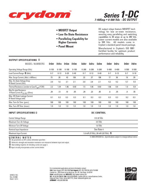
Max. Surge Current, [Adc] (10Msec) Max. On-State Voltage Drop @ Rated Current [Vdc] Thermal Resistance Junction to Case RqJC[°C/W] Max On-state Resistance @ Rated Current (R DS-ON ) [Ohms] Max. Off-State Leakage Current @ Rated Voltage [mA] Max. Turn-On Time [µsec]
MAX. SURGE CURRENT (Amps)
Transient Protection
All loads are inductive, even ones that are not so labeled. An inductive load will produce harmful transient voltages when it is turned off. The more perfect the switch, the larger the transient voltages; the MOSFET output is so nearly an ideal switch that the transient voltages produced by seemingly "non-inductive" loads can cause damage if not suppressed. Diodes should be fast recovery type with PIV rated greater than supply voltage.
8D报告格式
出现百分比
Percent Contribution:
确认日期
Effective Date:
5,选择永久纠正措施:Select Permanent Corrective Actions:
6,永久纠正措施实施及效果验证Permmentation and effectiveness verification:
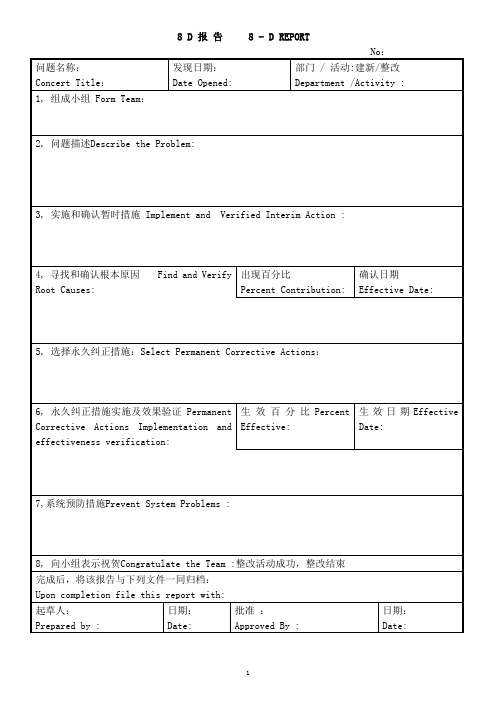
8 D报告8 - D REPORT
No:
问题名称:
Concert Title:
发现日期:
Date Opened:
部门/活动:建新/整改
Department /Activity :
1,组成小组Form Team:
2,问题描述Describe the Problem:
3,实施和确认暂时措施Implement and Verified Interim Action :
生效百分比Percent Effective:
生效日期Effective Date:
7,系统预防措施Prevent System Problems :
8,向小组表示祝贺Congratulate the Team :整改活动成功,整改结束
完成后,将该报告与下列文件一同归档:
Upon completion file this report with:
起草人:
Prepared by :
日期:
Date:
批准:
Approved By :
日期:
Date:
质保部批准:
Approved By QA:
日期:
Date:
用户批准(必要时):
Approved By Customer(as necessary):
AML1ETO通过活化EGR1抑制t(8;21)急性髓系白血病发生的机制研究中期报告
AML1ETO通过活化EGR1抑制t(8;21)急性髓系白血病发生的机制研究中期报告本研究旨在探究AML1-ETO(由t(8;21)染色体易位引起的急性髓系白血病相关的重要融合蛋白)通过活化EGR1(Early growth response-1)抑制t(8;21)急性髓系白血病的发生机制。
本研究已完成了实验室基础研究阶段,以下是中期报告的主要进展。
一、实验方法本研究采用了人急性髓系白血病细胞系K562和THP-1,以及小鼠造血干细胞作为实验材料,研究了AML1-ETO在白血病细胞中的表达及其对EGR1活性的影响,同时还构建了AML1-ETO和EGR1的重组表达质粒进行转染实验,以进一步验证它们之间的关系。
二、实验结果1. AML1-ETO的表达与EGR1的活性呈负相关通过Western Blot及qPCR实验,我们发现在白血病细胞系K562和THP-1中,AML1-ETO的表达水平相对较高,而EGR1的活性较低,二者呈现负相关(p<0.05)。
2. AML1-ETO可以抑制EGR1的转录活性我们构建了一个EGR1响应元素驱动的荧光素酶报告基因体系,通过转染AML1-ETO表达质粒,发现AML1-ETO可以抑制EGR1响应元素的转录活性(p<0.05)。
3. EGR1可以通过调节c-Fos和GADD45B介导AML1-ETO诱导的白血病细胞增殖和分化我们通过转染EGR1表达质粒,发现EGR1可以抑制AML1-ETO诱导的白血病细胞K562和THP-1的增殖和促进其分化;通过Western Blot 实验,发现EGR1可以下调c-Fos和上调GADD45B的表达水平。
三、结论通过相关实验结果,我们可以得出初步结论:1. AML1-ETO的过度表达抑制了EGR1的活性,进而参与了t(8;21)急性髓系白血病的发生。
2. AML1-ETO可以抑制EGR1活性,说明EGR1在AML1-ETO介导的白血病发生中可能具有重要的抑制作用。
UC2845J中文资料
UNITS
MIN TYP MAX
TJ = 25°C, IO = 1mA
4.95 5.00 5.05 4.90 5.00 5.10 V
12 ≤ VIN ≤ 25V
6
20
6
20 mV
1 ≤ I0 ≤ 20mA
6
25
6
25 mV
(Note 2) (Note 7)
0.2 0.4
0.2 0.4 mV/°C
Line, Load, Temp. (Note 2)
700 mW
Derating Factor Above TA ≤ 25°C
5.5 mW/°C
TA ≤ 70°C Power Rating
452 mW
2
TA ≤ 85°C Power Rating
370 mW
TA ≤ 125°C Power Rating
150 mW
元器件交易网
PLCC-20 (TOP VIEW) Q Package
SOIC-14, CFP-14. (TOP VIEW) D or W Package
UC1842/3/4/5 UC2842/3/4/5 UC3842/3/4/5
PACKAGE PIN FUNCTION
FUNCTION
PIN
N/C
1
COMP
2
N/C
SLUS223A - APRIL 1997 - REVISED MAY 2002
元器件交易网
ABSOLUTE MAXIMUM RATINGS(Note 1)
Supply Voltage (Low Impedance Source) . . . . . . . . . . . . . . 30V
DAC8411中文资料
VALUE –0.3 to +6 –0.3 to +AVDD +0.3 –0.3 to +AVDD +0.3 –40 to +125 –65 to +150
+150 (TJ max – TA)/θJA
250
UNIT V V V °C °C °C
HP惠普2011最新服务器介绍(必读)
品牌 型号 处理器 前端总线 最大处理器数量 标配内存 最大内存 标配硬盘 最大硬盘数量 最大硬盘容量
SCSI 设备槽位/空闲槽位 PCI插槽/64 bit/32 bit/空闲槽位 视频 保修
hp ML150 Xeon DP 2.4G 533MHz 2 256M 12GB 36GB 5 725G Ultra 320/2 通道 2/1
page 5
ProLiant ML110 特性
品质邦 品质生活 从此开始
• 2.8GHz Pentium 4 带有 512KB L2 缓存, Intel E7210 芯片组, 前端总 线为 800MHz
• 最大支持到4GB PC3200 DDR SDRAM 内存,带有 ECC 功能 • 最大支持到320GB ATA 非热插拔或
channel U3 SCSI
Tower; opt. rack enabling kit w/quick
deploy rails
1-1-1; opt 3-3-3 upgrade
PE400
Intel Pentium 4 2.6 – 3.2 GHz 512 cache
or Celeron 2.0 GHz, 128KB cache
IDC Q1 2003
品质邦 品质生活 从此开始
35% 30% 25%
20% Unit
15%
Rev.
10%
5%
0%
HP
Dell
IBM
Legend Langchao others
page 3
hp工业标准服务器[showing IA-32 servers only]
• 中小型商业环境:
– 有 1-250 员工