11.4 镶嵌
《天龙八部》不同等级宝石属性及镶嵌位置
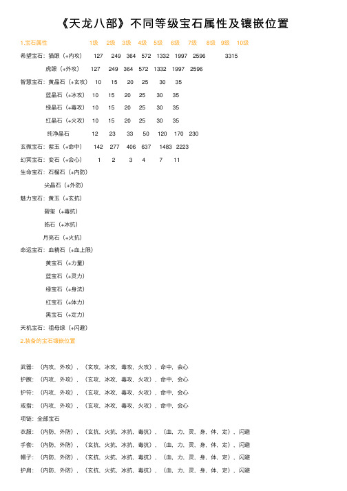
《天龙⼋部》不同等级宝⽯属性及镶嵌位置1.宝⽯属性 1级 2级 3级 4级 5级 6级 7级 8级 9级 10级希望宝⽯:猫眼(+内攻) 127 249 364 572 1332 1997 2596 3315虎眼(+外攻) 127 249 364 572 1332 1997 2596智慧宝⽯:黄晶⽯(+⽞攻) 10 15 20 25 30 35蓝晶⽯(+冰攻) 10 15 20 25 30 35绿晶⽯(+毒攻) 10 15 20 25 30 35红晶⽯(+⽕攻) 10 15 20 25 30 35纯净晶⽯ 12 23 33 50 120 170 230⽞微宝⽯:紫⽟(+命中) 142 277 406 637 1483 2223幻冥宝⽯:变⽯(+会⼼) 1 2 3 4 7 11⽣命宝⽯:⽯榴⽯(+内防)尖晶⽯(+外防)魅⼒宝⽯:黄⽟(+⽞抗)碧玺(+毒抗)皓⽯(+冰抗)⽉亮⽯(+⽕抗)命运宝⽯:⾎精⽯(+⾎上限)黄宝⽯(+⼒量)蓝宝⽯(+灵⼒)绿宝⽯(+⾝法)红宝⽯(+体⼒)⿊宝⽯(+定⼒)天机宝⽯:祖母绿(+闪避)2.装备的宝⽯镶嵌位置武器:(内攻,外攻),(⽞攻,冰攻,毒攻,⽕攻),命中,会⼼护腕:(内攻,外攻),(⽞攻,冰攻,毒攻,⽕攻),命中,会⼼护符:(内攻,外攻),(⽞攻,冰攻,毒攻,⽕攻),命中,会⼼戒指:(内攻,外攻),(⽞攻,冰攻,毒攻,⽕攻),命中,会⼼项链:全部宝⽯⾐服:(内防,外防),(⽞抗,⽕抗,冰抗,毒抗),(⾎,⼒,灵,⾝,体,定),闪避⼿套:(内防,外防),(⽞抗,⽕抗,冰抗,毒抗),(⾎,⼒,灵,⾝,体,定),闪避帽⼦:(内防,外防),(⽞抗,⽕抗,冰抗,毒抗),(⾎,⼒,灵,⾝,体,定),闪避护肩:(内防,外防),(⽞抗,⽕抗,冰抗,毒抗),(⾎,⼒,灵,⾝,体,定),闪避腰带:(内防,外防),(⽞抗,⽕抗,冰抗,毒抗),(⾎,⼒,灵,⾝,体,定),闪避鞋⼦:(内防,外防),(⽞抗,⽕抗,冰抗,毒抗),(⾎,⼒,灵,⾝,体,定),闪避。
din标紧固件地中文对照(1)
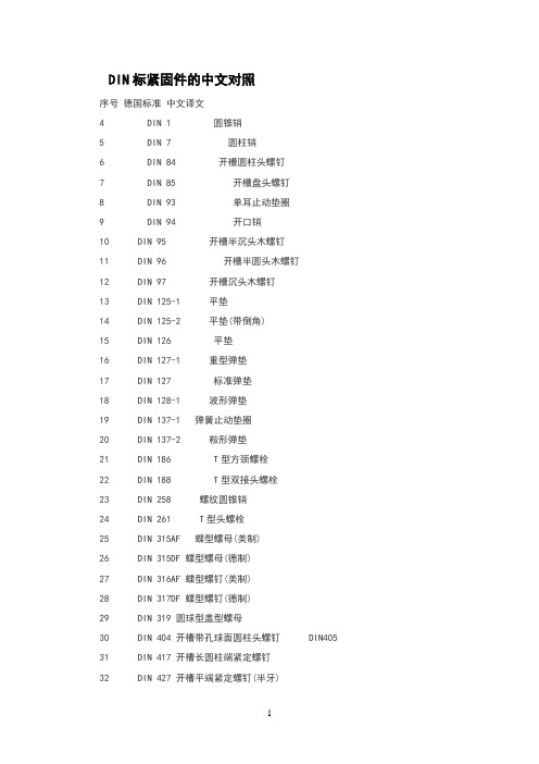
DIN标紧固件的中文对照序号德国标准中文译文4 DIN 1 圆锥销5 DIN 7 圆柱销6 DIN 84 开槽圆柱头螺钉7 DIN 85 开槽盘头螺钉8 DIN 93 单耳止动垫圈9 DIN 94 开口销10 DIN 95 开槽半沉头木螺钉11 DIN 96 开槽半圆头木螺钉12 DIN 97 开槽沉头木螺钉13 DIN 125-1 平垫14 DIN 125-2 平垫(带倒角)15 DIN 126 平垫16 DIN 127-1 重型弹垫17 DIN 127 标准弹垫18 DIN 128-1 波形弹垫19 DIN 137-1 弹簧止动垫圈20 DIN 137-2 鞍形弹垫21 DIN 186 T型方颈螺栓22 DIN 188 T型双接头螺栓23 DIN 258 螺纹圆锥销24 DIN 261 T型头螺栓25 DIN 315AF 蝶型螺母(美制)26 DIN 315DF 蝶型螺母(德制)27 DIN 316AF 蝶型螺钉(美制)28 DIN 317DF 蝶型螺钉(德制)29 DIN 319 圆球型盖型螺母30 DIN 404 开槽带孔球面圆柱头螺钉 DIN40531 DIN 417 开槽长圆柱端紧定螺钉32 DIN 427 开槽平端紧定螺钉(半牙)33 DIN 431 小六角特薄细牙螺母34 DIN 432 外舌止动垫圈35 DIN 433 小垫圈(用于圆柱头螺钉)36 DIN 434 方斜垫圈(U型)37 DIN 435 方斜垫圈(I型)38 DIN 436 方垫圈39 DIN 438 开槽凹端紧定螺钉40 DIN 439 六角薄螺母41 DIN 439 六角薄螺母 B级无倒角42 DIN 439 细牙六角薄螺母43 DIN 440 木螺钉专用垫圈44 DIN 443 密封帽45 DIN 444 活节螺栓B 型46 DIN 462 内舌止动垫圈47 DIN 463 双耳止动垫圈48 DIN 464 滚花高头螺钉49 DIN 465 开槽滚花高头螺钉50 DIN 466 滚花高螺母51 DIN 467 滚花薄螺母52 DIN 470 锁紧垫圈53 DIN 471 轴用弹性挡圈54 DIN 472 孔用弹性挡圈55 DIN 478 方头带垫螺栓56 DIN 479 方头圆柱底端螺栓57 DIN 480 方头带垫半圆底端螺栓58 DIN 481 弹性圆柱销59 DIN 508 T型槽螺母60 DIN 525 单头螺柱61 DIN 529 地脚螺栓62 DIN 546 带槽圆螺母63 DIN 547 端面带孔圆螺母64 DIN 551 开槽平端紧定螺钉65 DIN 553 开槽锥端紧定螺钉66 DIN 555 六角螺母67 DIN 557 方螺母-C68 DIN 558 六角头螺钉69 DIN 561 六角头圆柱端紧定螺钉70 DIN 562 薄型方螺母-B71 DIN 571 六角头木螺钉72 DIN 580 吊环螺钉73 DIN 582 吊环螺母74 DIN 601 六角头螺栓75 DIN 603 大半圆头方颈螺栓(马车螺栓) C级76 DIN 604 沉头带插销马车螺栓77 DIN 605 沉头长方颈马车螺栓78 DIN 607 半圆头带插销马车螺栓79 DIN 608 沉头短方颈马车螺栓80 DIN 609 六角头精配螺栓(长螺纹)81 DIN 610 六角头精配螺栓(短螺纹)82 DIN 653 滚花平头螺钉83 DIN 660 半圆头铆钉84 DIN 661 沉头铆钉85 DIN 662 半沉头铆钉86 DIN 674 大扁头铆钉87 DIN 703 重型侧面带孔圆螺母88 DIN 705 侧面带孔圆螺母89 DIN 741 卡头90 DIN 787 T型槽螺钉91 DIN 835 双头螺柱(牙长=2D)92 DIN 906 内六角锥型闭锁螺钉93 DIN 908 内六角直型闭锁螺钉94 DIN 909 外六角锥型闭锁螺钉95 DIN 910 外六角直型闭锁螺钉96 DIN 911 内六角扳手97 DIN 912内六角圆柱头螺钉98 DIN 913 内六角平端紧定螺钉99 DIN 914 内六角尖端紧定螺钉100 DIN 915 内六角圆柱端紧定螺钉101 DIN 916 内六角凹端紧定螺钉102 DIN 917 薄型盲螺母103 DIN 920 开槽小圆柱头螺钉104 DIN 921 开槽大圆柱头螺钉105 DIN 923 开槽圆柱头轴肩螺钉106 DIN 927 开槽无头轴肩螺钉107 DIN 928 焊接方螺母108 DIN 929 焊接六角螺母109 DIN 931 六角头螺栓(半牙)110 DIN 933 六角头螺栓(全牙)111 DIN 934 六角头螺母(1型)112 DIN 934-2 细牙六角头螺母(1型) 113 DIN 935 开槽六角螺母114 DIN 936 六角头薄螺母115 DIN 937 六角头开槽薄螺母116 DIN 938 双头螺距(牙长=1D)117 DIN 939 双头螺距(牙长=)118 DIN 939 双头螺距(牙长=)119 DIN 940 双头螺距(牙长=)120 DIN 960 六角头细牙螺栓(半牙)121 DIN 961 六角头细牙螺栓(全牙)122 DIN 962 头部穿孔六角头螺栓123 DIN 963 开槽沉头螺钉124 DIN 964 开槽半沉头螺钉125 DIN 965 十字槽沉头螺钉126 DIN 966 十字槽半沉头螺钉127 DIN 970 六角头螺母128 DIN 971 六角头螺母129 DIN 972 细牙六角头螺母(2型)130 DIN 975 牙条(全螺纹)131 DIN 976 螺纹销132 DIN 979 六角头开槽薄螺母(2型)133 DIN 980 全金属六角锁紧螺母(1型)134 DIN 981 圆螺母135 DIN 982 六角头尼龙锁紧螺母136 DIN 985 六角头薄型尼龙锁紧螺母137 DIN 986 六角盖型尼龙锁紧螺母138 DIN 988 配合垫片139 DIN 1052 木材连接用垫片140 DIN 1151 沉头钢钉141 DIN 1440 销钉专用垫片A型142 DIN 1441 销钉专用垫片143 DIN 1444 带头销钉144 DIN 1471 圆锥型槽销145 DIN 1472 圆锥型槽销(半槽)146 DIN 1473 平行槽销(带倒角)147 DIN 1474 前端凹槽槽销148 DIN 1475 中部凹槽槽销149 DIN 1476 圆头槽销150 DIN 1477 沉头槽销151 DIN 1479 六角螺母棒152 DIN 1480 花篮螺栓153 DIN 1481 弹性圆柱销开槽重型154 DIN 1587 组合式盖型螺母155 DIN 1804 开槽圆螺母(配合沟头扳手)156 DIN 1816 圆螺母(带插销孔)157 DIN 2093 盘型弹簧垫圈158 DIN 3017 喉箍159 DIN 3404 润滑油嘴(旋扭头)160 DIN 3567 管夹161 DIN 3570 U型螺栓162 DIN 5587 2型六角螺母 A和B级163 DIN 6319 球面垫圈164 DIN 6325 圆柱销165 DIN 6330 厚六角螺母166 DIN 6331 厚六角法兰面螺母167 DIN 6334 长六角螺母168 DIN 6797-A 外齿锁紧垫圈169 DIN 6797-I 内齿锁紧垫圈170 DIN 6798-A 外锯齿锁紧垫圈171 DIN 6798-I 内锯齿锁紧垫圈172 DIN 6799 开口挡圈173 DIN 6823 六角法兰面螺母174 DIN 6885 平键(A型)175 DIN 6888 半圆键176 DIN 6899 嵌环(支撑环)177 DIN 6900 机器螺钉和垫圈组合件178 DIN 6901 自攻螺钉和垫圈组合件179 DIN 6912 薄型带孔内六角圆柱头螺钉180 DIN 6914 大六角头螺栓181 DIN 6915 大六角螺母182 DIN 6916 大垫圈183 DIN 6917 楔型方垫圈184 DIN 6921 六角法兰面螺栓加大系列 B级185 DIN 6923 六角法兰面螺母186 DIN 6925 全金属六角锁紧螺母(2型)187 DIN 7337 开口型抽芯铆钉(沉头、扁圆头)188 DIN 7338 扁平头半空心/全空心铆钉189 DIN 7343 螺旋夹紧销190 DIN 7346 轻型弹性圆柱销191 DIN 7349 重型弹性圆柱销用垫圈192 DIN 7500 ISO公制螺纹螺钉(多种头型)193 DIN 7504 自攻自钻螺钉(多种头型)194 DIN 7513 开槽切削螺纹螺钉(多种头型) 195 DIN 7516 十字槽切削螺纹螺钉(多种头型) 196 DIN 7965 T型四爪螺母197 DIN 7968 钢结构用六角头螺栓连接副198 DIN 7971 开槽盘头自攻螺钉199 DIN 7972 开槽沉头自攻螺钉200 DIN 7973 开槽半沉头自攻螺钉201 DIN 7976 六角头自攻螺钉202 DIN 7978 圆锥销203 DIN 7980 圆柱头螺钉用弹簧垫圈204 DIN 7981 十字槽盘头自攻螺钉205 DIN 7982 十字槽沉头自攻螺钉206 DIN 7983 十字槽半沉头自攻螺钉207 DIN 7984 薄型内六角圆柱头螺钉208 DIN 7985 十字槽盘头螺钉209 DIN 7989 钢结构用垫圈210 DIN 7990 钢结构用六角头螺栓211 DIN 7991 内六角沉头螺钉212 DIN 7993 轴用钢丝挡圈213 DIN 7995 十字槽半沉头木螺钉214 DIN 7996 十字槽圆头木螺钉215 DIN 7997 十字槽沉头木螺钉216 DIN 8140 螺纹护套(普通\自锁等)217 DIN 9021 大外径垫圈218 DIN 11024 弹簧卡子219 DIN 13257 平板螺栓220 DIN 18182 干壁钉(墙板钉)221 DIN 28129 环型螺母222 DIN 70952 圆螺母用止退垫圈螺丝,紧固件,标准件词汇的中英文对照机(踏)车用螺丝、轴心 Screws And Shafts For Motorcycle Or Bicycle针车用螺丝、轴心 Screws And Shafts For Sewing Maching止付螺丝 Socket Set Screws不锈钢宽牙螺丝 Stainless Steel Coarse Thread Screws不锈钢高低牙螺丝 Stainless Steel High-Low Thread Screws不锈钢机械螺丝 Stainless Steel Machine Screws不锈钢钻尾螺丝 Stainless Steel Self Drilling Screws不锈钢自攻螺丝 Stainless Steel Self Tapping Screws不锈钢自削螺丝 Stainless Steel Thread Cutting Screws不锈钢三角牙螺丝 Stainless Steel Tri-Lobular Thread Screws插片壁虎 Steel Ceiling Anchors内迫壁虎 Drop in Anchors碳钢锤钉壁虎 Steel Hit Anchors碳钢六角螺帽 Steel Hex Coupling Nuts强力车修壁虎 Wedge Anchors外迫壁虎 Cut Anchors化学壁虎 Chemical Anchors不锈钢重载胀栓 Heavy Duty Expansion Anchors鱼眼壁虎企眼长螺帽 Tie Wire Anchors锌合金打入式壁虎 Hammer Drive Anchors弹簧螺帽 Strut Nuts兰花夹系列 Toggle Bolts (Spring Toggle & Gravity Toggle)门窗、地板专用壁虎 Nylon Frame Anchors or Metalframe Anchors石膏板中空壁虎 Hollow Wall Anchors套管式壁虎 Sleeve Anchors打入式壁虎鱼形尼龙壁虎 Nylon Frame Harmmer Fixing (Nylon Hammer Drive Anchors)强力式锤钉壁虎 Hit Anchors电梯壁虎 Bolt Anchors重载壁虎 Heavy duty anchors两片夹 Loxin Masonry Anchors定位螺栓 Set Bolts长型兰花夹 Short Strap Anchors工具棒 Drop in Setting Tools象脚壁虎 Elephant foot anchors水泥预埋件 Concrete Insert翻边胀轴 Drop in Anchor with Lip冲件 Legs Drywall Anchors六角盖头螺帽 Hex Cap Nuts六角锯齿螺帽 Hex Serrated Nuts六角轮缘螺帽 Hex Flange Nuts高脚螺帽 Hex Coupling Nuts(High Nuts)圆螺帽 Round Nuts四角螺帽 Square Nuts管用螺帽 Pipe Nuts轮壳螺帽 Wheel Nuts蝶型螺帽 Wing NutsU形螺帽 U NutsT形螺帽 T Nuts环首螺帽 Eye Nuts齿形螺帽 Kep Nuts齿花螺帽 Clinch Nuts耐候钢六角重型螺帽 Corten Steel Heavy Hex Nuts 焊接螺帽 Weld Nuts高张力螺帽 Heigh Strength Nuts建业用螺帽 Structural Nuts不锈钢螺帽 Stainless Steel Nuts铜螺帽 Brass Nuts铝螺帽 Aluminum Nuts合金钢螺帽 Alloy Steel Nuts重型车螺帽 Heavy Duty Wheel Hub Nuts铁器焊接袋帽 Acorn Cap Nuts金属预置扭矩式螺帽 All-Metal Prevailing Torque Type Nuts壁虎螺帽 Anchor Nuts大尺寸螺帽 Big Size Nuts铁盖袋帽 Closed End Acorn Nuts盘形华司螺帽 Conical Washer Nuts铁盖+尼龙圈组合盖帽 Din 986 Domed Cap Nuts突缘尼龙盖帽 Flange Nylon Insert Lock Nuts平面华司螺帽 Flat Waser Nuts六角割沟螺帽 Hex Slotted Nut自锁螺帽 Self-Locking Nuts制止螺帽 Sliding NutsSln-自动防松螺帽 Sln Self-Locking Nuts其它特殊螺帽 Special Nuts弹簧螺帽 Spring Nuts不锈钢突缘螺帽 Stainless Steel Flange Nuts不锈钢六角轮缘尼龙螺帽 Stainless Steel Flange Nylon Insert Lock Nuts 不锈钢六角重型螺帽 Stainless Steel Heavy Hex Nuts不锈钢六角螺帽 Stainless Steel Hex Nuts不锈钢尼龙嵌入螺帽 Stainless Steel Nylon Insert Lock Nuts普通六角螺帽 Hex Nuts六角重型螺帽 Heavy Hex Nuts薄型螺帽 Hex Jam Nuts尼龙嵌入防松螺帽 Nylon Insert Lock Nuts机械螺丝用六角螺帽 Hex Machine Screw Nut六角螺丝(栓) Hex Head Cap Screws(Hex Bolts)六角机械螺丝 Hex Head Machine Bolts六角木牙螺丝 Hex Lag Bolts四角螺丝 Square Head BoltsT头螺丝 T Head Bolts马车螺丝 Carriage Bolts环首螺丝 Eye Bolts内六角孔螺丝 Hex Socket Cap Screws固定螺丝 Set Screws螺椿栓 Stud Bolts螺旋椿 Screw Studs轮壳螺栓 Wheel Bolts翼形螺丝 Wing Screws自攻螺丝 Self Tapping Screws自削螺丝 Thread Cutting Screws钻尾螺丝 Self Drilling Screws旋入螺丝 Drive Screws机械螺丝 Machine Screws木螺丝 Wood Screws家具螺丝 Furniture Screws塑板螺丝 Chipboard Screws墙用螺丝 Drywall Screws基础螺栓 Foundation BoltsU型螺栓 U Bolts勾头螺栓 Hook Bolts套挂螺丝 Toggle Bolts突缘螺丝 Flange Bolts轨道螺栓(鱼尾螺丝) Track Bolts耐候钢螺丝 Corten Steel Heavy Hex Bolts扭矩控制螺栓高张力螺栓 High Strength Bolts剪力钉(焊接螺丝) Welding Studs螺丝附华司组合 Screws And Washers Assembled(Sems) 大尺寸螺栓 Big Size Bolts不锈钢小螺丝 Stainless Steel Sheet Metal Screws 不锈钢大螺丝 Stainless Steel Bolts铜螺丝 Brass Screws铝螺丝 Aluminum Screws合金钢螺丝 Alloy Steel Screws电子螺丝 Electronic Screws微小精密螺丝 Micro Screws塑料螺丝 Plastic Screws复合材料用螺丝 Particle Board Screws钛合金螺丝 Titanium Alloy Bolts钛、锆、钼、铌等螺丝、零件、材料 Ti,Zr,Mo,Nb Pare Metal Bolts Parts 拇指螺丝 Thumb Screws双头牙螺丝 Double End Screws Hanger Bolt车辆(汽车)螺丝、螺帽 Automotive Fasteners航天用螺丝 Aerospace Fasteners飞机特殊扣件 Source Control Bolts拉栓 Blind Bolts面板螺丝 Panel Fasteners电梯螺丝 Elevator Bolts四角头固定螺丝 Square Set Screws大头马车螺丝 Step Bolts单向螺丝 One Way Lag Screws管夹螺丝 Hose Clamp Screws不锈钢固定螺丝 Stainless Steel Hex Socket Cap Screws不锈钢内六角螺丝 Stainless Steel Hex Socket Cap Screws铰链螺丝 Hinge Screws货柜螺丝 Container Screws复合材料钻尾螺丝 Bi-Metal Self Drilling Screws三角牙螺丝 Trilobular Thread Screws高低牙螺丝 High Low Screws夹板用螺丝 Particle Board Screws马桶螺丝 Toilet Closet Bolts特长螺丝 Special Longer Screws建业螺丝 Building Fasteners不锈钢六角螺丝 Stainless Steel Hex Socket Cap Screws其它特殊螺丝 Special Screws Or Bolts不锈钢特殊螺丝 Special Stainless Steel Screws宽牙螺丝(粗牙螺丝) Coarse Thread Screws链带螺丝 Collated Screws水泥螺丝 Concrete Screws板模螺丝 Construction Bolts锌蝶螺丝 Die Cast Wing Screws; Zinc Alloy重型车螺丝 Heavy Duty Wheel Hub Bolts内六角固定螺丝 Hex Socket Set Screws复合材料用螺丝(夹板用) Particle Board Screws犁壁螺丝 Plow Bolts不锈钢木螺丝 Stainless Steel Wood Screws套挂螺栓及螺丝 Toggle Bolts钛合金膨胀螺丝 Titanium Alloy Expansion Bolts六角盖头螺帽 Hex Cap Nuts六角锯齿螺帽 Hex Serrated Nuts六角轮缘螺帽 Hex Flange Nuts高脚螺帽 Hex Coupling Nuts(High Nuts)圆螺帽 Round Nuts四角螺帽 Square Nuts管用螺帽 Pipe Nuts轮壳螺帽 Wheel Nuts蝶型螺帽 Wing NutsU形螺帽 U NutsT形螺帽 T Nuts环首螺帽 Eye Nuts齿形螺帽 Kep Nuts齿花螺帽 Clinch Nuts耐候钢六角重型螺帽 Corten Steel Heavy Hex Nuts焊接螺帽 Weld Nuts高张力螺帽 Heigh Strength Nuts建业用螺帽 Structural Nuts不锈钢螺帽 Stainless Steel Nuts铜螺帽 Brass Nuts铝螺帽 Aluminum Nuts合金钢螺帽 Alloy Steel Nuts重型车螺帽 Heavy Duty Wheel Hub Nuts铁器焊接袋帽 Acorn Cap Nuts金属预置扭矩式螺帽 All-Metal Prevailing Torque Type Nuts壁虎螺帽 Anchor Nuts大尺寸螺帽 Big Size Nuts铁盖袋帽 Closed End Acorn Nuts盘形华司螺帽 Conical Washer Nuts铁盖+尼龙圈组合盖帽 Din 986 Domed Cap Nuts突缘尼龙盖帽 Flange Nylon Insert Lock Nuts平面华司螺帽 Flat Waser Nuts六角割沟螺帽 Hex Slotted Nut自锁螺帽 Self-Locking Nuts制止螺帽 Sliding NutsSln-自动防松螺帽 Sln Self-Locking Nuts其它特殊螺帽 Special Nuts弹簧螺帽 Spring Nuts不锈钢突缘螺帽 Stainless Steel Flange Nuts不锈钢六角轮缘尼龙螺帽 Stainless Steel Flange Nylon Insert Lock Nuts 不锈钢六角重型螺帽 Stainless Steel Heavy Hex Nuts不锈钢六角螺帽 Stainless Steel Hex Nuts不锈钢尼龙嵌入螺帽 Stainless Steel Nylon Insert Lock Nuts锌压属螺帽 Zinc Die Casting Nuts普通六角螺帽 Hex Nuts六角重型螺帽 Heavy Hex Nuts薄型螺帽 Hex Jam Nuts尼龙嵌入防松螺帽 Nylon Insert Lock Nuts机械螺丝用六角螺帽 Hex Machine Screw Nut合金钢线材盘元 Alloy Steel Wire Rod球状化线材 Annealing Wire And Rod黑铁丝 Black Wire黄铜棒线 Brass Wire And Rod磨光棒钢 Bright Steel Bar(Hex/Round/Square)铜合金线 Copper Alloy Wire线切割线 Cutting Wire快削钢线材盘元 Free Cutting Steel Wire Rod线材 Iron Or Steel Wire线材盘元 Iron Or Steel Wire Rod洋白铜线 Nickel Silver Wire磷青铜线 Phosphate Bronze Wire不锈钢条棒 Stainless Steel Bar(Round/Hex/Square)不锈钢冷锻线材 Stainless Steel Cold Heading Wire不锈钢线(抽线后) Stainless Steel Draw Wire不锈钢线材 Stainless Steel Wire不锈钢线材及盘元 Stainless Steel Wire And Rod棒钢 Steel Bar(Hex/Round/Square)转回90度碾线头机 90讧evolving Wire Twisting Machine气动拉钉机 Air Riveter各式螺丝类产品自动包装 Automatic Packaging For All Kinds Of Packaging 自动包装机 Automatic Packing Machine螺丝制造搓牙机械 Automatic Thread Rolling Machine螺丝割尾加工机械 Automatic Thread Slotting Machine螺丝制造成型机械 Automatic Trimming Machine拉钉打头机 Blind Rivet Heading Machine螺丝、螺帽成型机 Bolt Formers,Nuts Formers,Headers螺丝、螺帽热处理 Bolt Nut And Screws Heat Treatment螺丝、螺帽热处理炉 Bolt Nut And Screws Heat Treatment Furnaces球状化电器炖炉 Carburizing Furnace Vacuum And Bell Type Furnace超防锈复合瓷膜 Ceramic Coating连续式光辉渗碳淬火炉 Continuous Bright Carburizing Quenching Furnace 连续式光辉调质淬火炉 Continuous Bright Hardening Quenching Furnace 中、高热镀锌光辉连续炉 Continuous Bright Heat Treat Furnace连续式光辉热处理炉 Continuous Type Bright Heat Treatment Furnace螺丝割尾及特殊割遘加工 Machine Screw Shank Slotting螺丝钻孔加工 Screw Shank Drilling鸡眼上下模 Eyelets Dies一般线材、盘元、退火炉 General Wire,Wire Rod,Annealing Furnace倒立式滑落型伸线机 Handstand Type Wire Drawing Machine十字冲模 Header Punches In Various Drives成型冲模 Header Punches In Various Drives螺丝打头机 Heading Machine螺丝制造高速搓牙机械 High Speed Automatic Thread Rolling Machine高中低周波感应加热炉 High,Medium,Low Frequency Induction Heater空心打头机 Hollow Heading Machine热浸镀锌螺丝、螺帽 Hot Dip Galvanizing Bolts And Nuts机械镀锌 Mechanical Galvanized迷你成型机 Mini-Formers成品自动收线机 Non-Stop Coiler精抽自动收线机 Non-Stop Coiler(Skinpass)螺帽模 Nut Forming Dies螺帽成型模 Nuts Formers特殊零件成型机 Parts Forming Maching冲模 Punch Dies冲子 Punch Pins罗拉成型机 Rollers Formers机(踏)车用螺丝成型机 Screw For Motorcycle Or Bicycle Heading Machine止付螺丝成型机 Set Screws Formers套高成型机 Sockets Formers一般线材、盘元、螺丝合金炖炉 Spheroidizing Bright Annealing Furnace球状化热处理炉 Spheroidizing Heat Treatment Furnace攻牙机 Tapping Machine螺丝攻、车刀、模具 Taps Dies And Tools搓牙机铁屑分离装置 Thread Chip Separator滚牙轮 Thread Rolling Dies牙板 Thread Rolling Dies Plates精密油压滚牙机 Hydraulic Thread Rolling Machines模具 Tools六角整头模 Trimming Dies Hexagan碳化钨模具 Tungsten Carbide Die镀钛处理(Tin)专业加工服务 Tin Hard Coating For Cutting Tools And Punch By Pvd 电镀化学原料 Various Electroplating Chemicals环规校正 Calibration For Ring Gage环规、牙规、三线规校正 Calibration For Ring Gage, Athread Gage, 3 Wire Gage 螺丝、螺帽品检量测仪器 Fasteners Inspection And Measurement Instruments螺丝、螺帽成型攻牙专用油 Forming And Tapping Oils For Bolts And Nuts Formers 螺丝、螺帽五金等检验 Insptection Services For Fasteners And Hardware德国schatz扭力机代理 Representative Of Schatz Torque MachinIso品质保证系统 Iso Quality Assurance System生产管理系统 Production Control System物料管理系统 Material Control System齿轮 Gears不锈钢牙条棒 Stainless Steel Hread Rod马达轴承轴心组件 Bearing Shaft(Motor)轴承轴心 Bearing Shaft开口铆钉 Blind Rivets长形拉帽 Blind Rivet Nuts拉帽 Blind Nuts拉钉 Blind Rivets实心梢 Clevis Pins And Straight Pins弹片 Clips卷钉 Coil Nails冷锻零件 Cold Forming Part开口销 Cotter PinsE型环 E-Rings膨胀螺栓 Expansion Anchor Bolts鸡眼钉 Eyelets RivetsR型销 Snap Pins闸、锁 Latches And Keeper Assembleds其它特殊铆钉 Other Specil Rivets销 Pins格式管夹、管束 Pipe Hanger铆钉 Rivets螺旋锔及螺旋圈 Screw Hook And Screw Rings 中空钉 Semi-Tubular Rivet开叉钉 Split Drive Anchors弹簧华司 Spring Washers弹簧蝴蝶夹 Spring Wings不锈钢华司 Stainlesssteel Washers钢铁钉 Steel And Iron Nails搓牙铁钉 Thread Nails钛合金铆钉 Titaium Alloy Rivets管形铆钉 Tubular Rivets华司 Washers真空热处理 Vacuum Heat Treatment螺丝、螺帽、五金、Diy扣件 Fasteners合金钢工具 Alloy Steel Tools螺栓模 Bolt Heading Dies手动拉钉钳 Hand Riveter船舶链 Anchor Chain脚踏车链锁 Bicycle Chain Locks螺丝起子 Bit罗拉 Chain Roller特殊铆合扣件 Collars(A Blindfastener For Huck Intl)装饰链 Decorative Chains自攻螺纹衬套 Ensat Threaded Inserts六角扳手 Hexagon Keys超音螺纹压入式螺纹自动锁扣 Threaded Inserts For Plastic Injection Mouldeings 汽车特殊杆接件 Special Auto-Mobile Fastener As Your Needs螺纹护套 Recoil Inserts链条用滚子 Roller For Roller Chain金属板镶嵌组件及自动夹扣组件 Sheet Metal Fasteners工具套筒组件 Socket Wrench Sets不锈钢链 Stainless Steel Chains轭子 T-Yoke轮胎链 Tire Chains狗链 Dog Chains喇叭头轭铁 U-Yoke,T-Yoke For Speaker不锈钢输送带轮用轨道 Stainless Wheel's Rack For Transporter工业用链 Industrial Steel Link Chains拖链安全链 Tow Chains And Safety Chains机车离合器零件 Manufacture Of Motorcycle's Cvt Parts牙条棒 Thread Rod。
ASTM B164 Standard Specification for Nickel-Copper Alloy Rod, Bar, and Wire1

Yield Strength (0.2 % offset)A
min. psi (MPa)
UNS N04400
Cold-worked (as worked): Rounds under 1⁄2 (12.7) Squares, hexagons, and rectangles under 1⁄2 (12.7)
4.1.1 ASTM designation and year of issue. 4.1.2 UNS number. 4.1.3 Section—Rod (round) or bar (square, hexagonal, or rectangular) or wire (round). 4.1.4 Dimensions—Dimensions including length. 4.1.5 Condition. 4.1.6 Finish. 4.1.7 Quantity—feet or number of pieces. 4.1.8 Certification—State if certification is required. 4.1.9 Samples for Product (Check) Analysis—State whether samples for product (check) analysis should be furnished.
NOTE 1—Hot-worked rectangular bar in widths 10 in. and under may be furnished as hot-rolled plate with sheared or cut edges in accordance with Specification B 127, provided the mechanical property requirements of Specification B 164 are met.
高效粉碎机urs
高效粉碎机用户需求标准URS目录1.目的 (1)2.法规要求 (1)3.概述 (1)4.设备机械部分、系统和部件的要求 (1)5.安装要求 (2)6.运行要求 (3)7.仪表控制要求................................................................................................ (3)8.电气自动控制要求 (3)9.安全、环保要求 (3)10.文件资料要求 (4)11.服务要求 (4)11.1产品标识要求 (4)11.2包装运输要求 (4)11.3备品配件要求 (5)11.4 工厂验收测试FAT (5)11.5 现场验收测试SAT要求 (5)11.6培训要求 (6)10.7保修要求 (6)1.目的制订该文件的目的是定义宜昌长江药业有限公司拟购置的口服固体制剂车间高效粉碎机的规格和性能要求,在设备的设计、制造、采购、验收和确认等过程中,为用户和供应商提供依据,也是与选定的设备供应商签订的购买合同的一个主要部分。
2.法规要求3.概述宜昌长江药业有限公司拟购置1台高效粉碎机,安装于建筑物A05三楼新建的口服固体制剂车间。
该设备用于口服固体制剂车间各种物料的粉碎。
设备具体的规格/型号由合同制造商根据制药机械GEP(工程设计规范)提出。
11.服务要求11.6培训要求名句赏析!!!!!不限主题不限抒情四季山水天气人物人生生活节日动物植物食物山有木兮木有枝,心悦君兮君不知。
____佚名《越人歌》人生若只如初见,何事秋风悲画扇。
____纳兰性德《木兰词·拟古决绝词柬友》十年生死两茫茫,不思量,自难忘。
____苏轼《江城子·乙卯正月二十日夜记梦》只愿君心似我心,定不负相思意。
____李之仪《卜算子·我住长江头》玲珑骰子安红豆,入骨相思知不知。
____温庭筠《南歌子词二首/ 新添声杨柳枝词》曾经沧海难为水,除却巫山不是云。
微镶
微镶钻戒绝不等于裸钻加金子。
一件珠宝,设计和工艺应该更被关注,只有完美切工的裸钻+工艺精湛、设计别致的钻戒才能成为一生一爱的永恒见证。
需要指出的是,并不是所有的豪华群镶款就是微镶,真正的微镶是在显微镜下进行钻石镶嵌的,呈现的效果是“见石不见金”。
在岁月的蹉跎中,金属会因磨损而黯淡,只有钻石会恒久璀璨。
小钻在筛选过程中,要保证小石的直径一致,重量均衡,每一个筛号严格把关。
戒托上的小钻必须采用57-58个切面的钻石,确保钻戒的恒久璀璨。
高工艺的微镶在镶嵌小钻之前必须做到抛光完全,包括先钻的石空部位,也要光亮并且电镀到位。
微镶(适用于1.5mm以下的宝石)1)金属表面处理光亮。
2)在金属表面整齐排列宝石位置,做宝石台位。
3)宝石之间的距离留出0.2~0.3mm左右。
4)铲边要顺、光,形成小爪。
5)表面用毛刷轻刷,使宝石台位洞内光亮。
6)分出大小一致的小爪,再把爪进行吸珠。
7)镶石在显微镜下操作,使宝石均匀,平整排列,台面要高度一致。
8)使用毛刷摩擦,使小爪更光滑微镶技术是比较新的技术,是早几年前从美国引进的,目前在中国的珠宝首饰公司中用这种技术已经开始普片。
微镶技术是一种镶嵌工艺种要求比较高,相对复杂的一种镶法,它又称之为微钉镶,顾名思义,这种镶法的钉看上去非常细小,通常需要借助放大镜来观察,石头镶上后有一种浮着的感觉,是一种能够极好的体现钻石光彩的方法。
微镶技术它同钉镶技术基本相同,都是用小钻石镶成,但微镶的钉比钉镶小许多,钻石互相间的镶嵌很紧密,故不显金属,微镶的表面看上去全由钻石铺平。
微镶基本上可取代传统的钉镶,用微镶的方法镶出来的首饰比钉镶的工艺精美得多,因为微镶的边铲得直且光滑,钉也比较细,清晰且圆。
珠宝首饰微镶设备包括:显微镜、微镶机、金属模注蜡机、辘珠边机、抛光机、首饰磨打台,首饰执模台、珠宝首饰微镶机配件及工具等系列产品。
微镶技术是一个相当复杂的工艺技术,该技术在生产时有相当高的工艺要求。
镶嵌怎么操作方法

镶嵌怎么操作方法镶嵌是一种常见的饰品加工技术,常用于珠宝、首饰和仿古工艺品的制作中。
它利用金属制品表面制作一个或多个凹槽,将宝石或其他装饰物嵌入其中,以增加装饰物的美观和装饰效果。
下面将详细介绍镶嵌的操作方法。
1. 准备工作在进行镶嵌之前,首先需要准备一些工具和材料。
常用的工具有:落料机、刻槽刀、切割机、针嘴、夹钳、焊炬、打磨机等。
常用的材料有:金属制品、宝石、石英和玻璃胶等。
2. 凹槽刻制首先,需要在金属制品表面制作一个或多个适合装饰物嵌入的凹槽。
可以使用落料机或刻槽刀来进行刻制。
根据装饰物的形状和大小,选择合适的刀具和刻槽深度,谨慎操作刻制凹槽。
3. 装饰物准备凹槽刻制完成后,根据设计需要,选择合适的装饰物。
装饰物可以是宝石、钻石、珍珠、彩色玻璃、陶瓷等。
根据装饰物的大小和形状,选择合适的切割机进行切割。
注意安全操作,避免受伤。
4. 装饰物镶嵌将切割好的装饰物放入凹槽中,使用针嘴和夹钳进行固定。
注意调整装饰物的位置和角度,使其达到最佳的镶嵌效果。
使用焊炬加热金属制品,使其表面的焊料熔化并固定装饰物。
焊接时需要注意火焰温度和焊接时间,避免金属变形或装饰物损坏。
5. 补充共位装饰物镶嵌完成后,可能会出现一些凹槽未被装饰物填满的情况。
这时可以使用玻璃胶或其他合适的胶水进行补充填充。
将胶水涂抹在凹槽上,然后将适合的装饰物小块嵌入其中,待胶水干燥后,用打磨机进行修整。
6. 打磨和抛光镶嵌完成后,需要进行打磨和抛光,使表面光滑且具有良好的光泽。
使用打磨机将表面不平整的部分进行修整,然后使用抛光机去除瑕疵并增加光泽。
注意操作细节,避免损坏装饰物。
7. 清洁和保养完成镶嵌后,及时清洁和保养装饰物是非常重要的。
可以使用温水和中性清洁剂轻轻擦拭装饰物,然后用干净的软布擦干。
避免与化学物品接触,避免碰撞和摩擦,保持装饰物的美观和耐用性。
以上是镶嵌的基本操作方法。
通过准备工作、凹槽刻制、装饰物准备、装饰物镶嵌、补充共位、打磨和抛光以及清洁和保养等步骤,可以制作出精美的镶嵌饰品。
Web GIS原理与应用开发
7.2.2 在 OpenLayer s中使用KML
七 在客户 端绘制矢 量数据
7.3 使用GeoJSON
A
7.3.1 GeoJSON简介
7.3.2 在 OpenLayers中使
用GeoJSON
B
七 在客户端绘制矢 量数据
7.6 实践12:访问用户KML 数据
三 空间数据的存储与处理
3.6.1 安装 PostGIS
3.6.2 创建空 间数据库
3.6.3 导入空 间数据
3.6 实践5:PostGIS的安装与初步 使用
四 使用WMS在服务器端绘制与查询地图
04
四 使用WMS在服务器端绘制与查询地图
A
C
E
4.2 WMS规范 基础
4.4 实践6:使用 GeoServer发布
10
十 WCS及多维数据
10.1 WCS及其操作
10.3 实践15:多维数据 WCS的发布
10.5 习题
10.2 多维数据与图像镶 嵌插件
10.4 实践16:在 OpenLayers中访问WCS
十 WCS及多维数据
10.1.1 GetCapabilities操作
A
10.1.2 DescribeCoverage操作
A
5.3.2 使用开源软 件创建切片
B
5.3 创建与提供切片地图服务的策 略
5.5.1 使用TileMill设计地图
5.5.3 发布与测试切片
五 切片地图
5.5 实践9:使用TileMill创建切片
5.5.2 输出与提取地图切片
六 使用Web地图API访问地图服务
06
六 使用Web地图API访问地图服务
DIN 471-2011-04 ENG
April 2011Translation by DIN-Sprachendienst.English price group 12No part of this translation may be reproduced without prior permission ofDIN Deutsches Institut für Normung e. V., Berlin. Beuth Verlag GmbH, 10772 Berlin, Germany,has the exclusive right of sale for German Standards (DIN-Normen).ICS 21.060.60; 21.120.10!$t+4"1810817www.din.de DDIN 471Retaining rings for shafts –Normal type and heavy typeEnglish translation of DIN 471:2011-04Sicherungsringe (Halteringe) für Wellen –Regelausführung und schwere Ausführung Englische Übersetzung von DIN 471:2011-04Anneaux d’arrêt pour arbres –Type standard et type robusteTraduction anglaise de DIN 471:2011-04©SupersedesDIN 471:1981-09www.beuth.deIn case of doubt, the German-language original shall be considered authoritative.Document comprises 24 pages10.11DIN 471:2011-04A comma is used as the decimal marker.Contents PageForeword (3)1 Scope (4)references (4)2 Normative3 Symbols (5)4 Dimensions and design details (6)5 Material (16)6 Finish (16)7 Testing (17)the material (17)7.1 Testingfracture test (17)and7.2 Benddeformation (17)the7.3 Testingtheconical deformation (17)7.3.1 Testingspiral flatness (18)the7.3.2 Testing7.4 Testing the function (permanent set and grip test) (18)7.5 Acceptance inspection (18)bearing capacity (19)8 Load8.1 General (19)8.2 Load bearing capacity of groove F N (19)8.3 Load bearing capacity of retaining ring F R (19)speed (20)9 Detaching10 Design of the groove (21)d2 (21)diameter10.1 Groovem (21)width10.2 Groove10.3 Design of the groove base (22)11 Assembly (23)12 Designation (24)2DIN 471:2011-04ForewordThis standard has been prepared by Working Committee NA 067-00-09 AA Verbindungselemente ohne Gewinde of the Normenausschuss Mechanische Verbindungselemente (Fasteners Standards Committee). Attention is drawn to the possibility that some of the elements of this document may be the subject of patent rights. DIN shall not be held responsible for identifying any or all such patent rights.AmendmentsThis standard differs from DIN 471:1981-09 as follows:a) normative references have been updated;b) the specifications for load bearing capacity, detaching speed and assembly have been revised;c) the tolerances on radial run-out have been deleted from Figure 2 (formerly Figure 3);d) in Clause 10, Figure 11 (formerly Figure 14) “Taper assembly” has been revised;e) Figure 10 “Design of groove base” has been included in 10.3;f) examples of designation for retaining rings with corrosion protection have been included;g) the standard has been editorially revised.Previous editionsDIN 471: 1941-12, 1942-11, 1952-01, 1954-01, 1981-09DIN 471 and DIN 472 Supplement 1: 1945-01, 1954x-03DIN 471-1: 1965-03DIN 471-2: 1965-03DIN 995: 1970-013DIN 471:2011-041 ScopeThis standard specifies requirements for retaining rings for shafts and lays down design details for the grooves into which such rings are fitted.NOTE Retaining rings are used to hold components or assemblies (e.g. rolling bearings) on shafts and are suitable for the transmission of axial forces.2 Normative referencesThe following referenced documents are indispensable for the application of this document. For dated references, only the edition cited applies. For undated references, the latest edition of the referenced document (including any amendments) applies.DIN 988, Shim rings and supporting ringsDIN 5254, Pliers for retaining rings for shaftsDIN 50938, Black oxide coatings on iron or steel — Requirements and test methodsDIN EN 10132-4, Cold-rolled narrow steel strip for heat-treatment — Technical delivery conditions — Part 4: Spring steels and other applicationsDIN EN 12476, Phosphate conversion coatings of metals — Method of specifying requirementsDIN EN ISO 3269, Fasteners — Acceptance inspectionDIN EN ISO 4042, Fasteners — Electroplated coatingsDIN EN ISO 6507-1, Metallic materials — Vickers hardness test — Part 1: Test methodDIN EN ISO 6508-1, Metallic materials — Rockwell hardness test — Part 1: Test method (scales A, B, C, D, E, F, G, H, K, N, T)DIN EN ISO 9227, Corrosion tests in artificial atmospheres — Salt spray testsDIN EN ISO 18265, Metallic materials — Conversion of hardness valuesDIN ISO 2859-1, Sampling procedures for inspection by attributes — Part 1: Sampling schemes indexed by acceptance quality limit (AQL) for lot-by-lot inspection4--`,,,,```,,,,,,`````,,,,,`,`-`-`,,`,,`,`,,`---DIN 471:2011-043 Symbolsa radial width of the lugb radial width of retaining ring opposite the aperturec distance between measuring plates for testing spiral flatnessd1shaft diameterd2groove diameterd3internal diameter of retaining ring in the unstressed state--`,,,,```,,,,,,`````,,,,,`,`-`-`,,`,,`,`,,`---d4maximum centre line diameter of external clearance during assembly, to be calculated from: d4 = d1 + 2,1 ad5diameter of the assembly holesE modulus of elasticityF force acting on the retaining ring when testing conical deformationF N load bearing capacity of groove at a yield point of the grooved material of 200 MPa (see 8.2)F R load bearing capacity of retaining ring with sharp-edged abutment of a machine component (see 8.3) F Rg load bearing capacity of retaining ring for abutment with edge distance g (see 8.3)g edge distance of the machine component abutting the retaining ringh distance between the plates when testing conical deformationm groove widthn edge marginn abl detaching speed of the retaining ring (see Clause 9)R eL yield pointr curvature in the groove base or test jawss thickness of retaining ringt groove depth with nominal sizes of d1 and d25DIN 471:2011-044 Dimensions and design detailsThe designs shown in Figure 1 are for illustrative purposes only; however, the dimensions of retaining rings and grooves shall be as specified in Tables 1 and 2. The tolerances specified relate to retaining rings in their uncoated condition.UnstressedShape of ring at manufacturer’s discretiona)b)Detail Xd 1 ≤ 9 mm9 mm < d 1 ≤ 300 mmd 1 ≥ 170 mm at manufacturer’sdiscretionKey1 External clearanceFigure 1 — Dimensions of retaining ring (notation)6--`,,,,```,,,,,,`````,,,,,`,`-`-`,,`,,`,`,,`---DIN 471:2011-047Figure 2 — Example of installationValues for peak-to-valley height for groove base and loaded edge shall be specified in each case. The design of the groove base shall be as specified in 10.3.--`,,,,```,,,,,,`````,,,,,`,`-`-`,,`,,`,`,,`---DIN 471:2011-048Table 1 — Normal typeDimensions in millimetresRing Groove Supplementary data dShaft diameterd 1 s d 3 ab ad 5Mass per 1 000 units in kgd 2bm ctn 4d 4F NF RgF Rgn ablNominal sizeperm.dev.perm. dev.max. ≈ min.≈perm.dev.H13 min. kN kN kN min −1Nominalsize of pliers as in DIN 52543 0,4 2,7 1,9 0,8 1,0 0,017 2,8−0,040,5 0,10 0,3 7,0 0,15 0,47 0,5 0,27 360 000 4 0,4 3,7 2,2 0,9 1,0 0,022 3,8 0,5 0,10 0,3 8,6 0,20 0,50 0,5 0,30 211 000 5 0,6 4,7 2,5 1,1 1,0 0,066 4,8 0,7 0,10 0,3 10,3 0,26 1,00 0,5 0,80 154 0006 0,7 5,6 +0,04 −0,15 2,7 1,3 1,2 0,084 5,7 0 −0,05 0,8 0,15 0,5 11,7 0,46 1,45 0,5 0,90 114 000 7 0,8 6,5 3,1 1,4 1,2 0,121 6,7 0,9 0,15 0,5 13,5 0,54 2,60 0,5 1,40 121 000 8 0,8 0 −0,05 7,4 3,2 1,5 1,2 0,158 7,6 0−0,06 0,9 0,20 0,6 14,7 0,81 3,00 0,5 2,00 96 000 9 1,0 8,4 +0,06 −0,183,3 1,7 1,2 0,300 8,6 1,1 0,20 0,6 16,0 0,92 3,50 0,5 2,40 85 000310 1,0 9,3 3,3 1,8 1,5 0,340 9,6 1,1 0,20 0,6 17,0 1,01 4,00 1,0 2,40 84 000 3; 10 11 1,0 10,2 3,3 1,8 1,5 0,410 10,5 1,1 0,25 0,8 18,0 1,40 4,50 1,0 2,40 70 000 12 1,0 11,0 3,3 1,8 1,7 0,500 11,5 1,1 0,25 0,8 19,0 1,53 5,00 1,0 2,40 75 00013 1,0 11,9 3,4 2,0 1,7 0,530 12,4 1,1 0,30 0,9 20,2 2,00 5,80 1,0 2,40 66 000 14 1,0 12,9 3,5 2,1 1,7 0,640 13,4 1,1 0,30 0,9 21,4 2,15 6,35 1,0 2,40 58 000 15 1,0 13,8 3,6 2,2 1,7 0,670 14,3 1,1 0,35 1,1 22,6 2,66 6,90 1,0 2,40 50 000 16 1,0 14,7 3,7 2,2 1,7 0,700 15,2 1,1 0,40 1,2 23,8 3,26 7,40 1,0 2,40 45 000 171,00 −0,06 15,7+0,10 −0,36 3,8 2,3 1,7 0,820 16,2−0,111,1 0,40 1,2 25,0 3,46 8,00 1,0 2,40 41 00010 See page 13 for a, b, c and d .--`,,,,```,,,,,,`````,,,,,`,`-`-`,,`,,`,`,,`---DIN 471:2011-049Table 1 (continued)Dimensions in millimetresRingGroove Supplementary data d Shaft diameterd 1 s d 3 ab ad 5Mass per 1 000 units in kgd 2bm ctn 4d 4F NF RgF Rgn ablNominal size perm.dev.perm. dev.max. ≈ min.≈perm.dev.H13 min. kN kN kN min −1Nominal size of pliers as in DIN 525418 1,20 16,5 3,9 2,4 2,0 1,11 17,0 1,30 0,50 1,5 26,2 4,58 17,0 1,5 3,75 39 000 10 19 1,20 17,5 +0,10 −0,36 3,9 2,5 2,0 1,22 18,0 0−0,11 1,30 0,50 1,5 27,2 4,48 17,0 1,5 3,80 35 000 20 1,20 18,5 4,0 2,6 2,0 1,30 19,0 1,30 0,50 1,5 28,4 5,06 17,1 1,5 3,85 32 000 21 1,20 19,5 4,1 2,7 2,0 1,42 20,0 1,30 0,50 1,5 29,6 5,36 16,8 1,5 3,75 29 00022 1,20 20,5 +0,13 −0,42 4,2 2,8 2,0 1,50 21,0 0−0,13 1,30 0,50 1,5 30,8 5,65 16,9 1,5 3,80 27 000 24 1,20 22,2 4,4 3,0 2,0 1,77 22,9 1,30 0,55 1,7 33,2 6,75 16,1 1,5 3,65 27 000 25 1,20 23,2 4,4 3,0 2,0 1,90 23,9 1,30 0,55 1,7 34,2 7,05 16,2 1,5 3,70 25 000 10; 1926 1,20 24,2 4,5 3,1 2,0 1,96 24,9 1,30 0,55 1,7 35,5 7,34 16,1 1,5 3,70 24 000 28 1,50 25,9 4,7 3,2 2,0 2,92 26,6 1,60 0,70 2,1 37,9 10,00 32,1 1,5 7,50 21 200 29 1,50 26,9 4,8 3,4 2,0 3,20 27,6 1,60 0,70 2,1 39,1 10,37 31,8 1,5 7,45 20 000 30 1,50 27,9 5,0 3,5 2,0 3,31 28,6 0−0,21 1,60 0,70 2,1 40,5 10,73 32,1 1,5 7,65 18 900 32 1,50 29,6 +0,21 −0,425,2 3,6 2,5 3,54 30,31,60 0,85 2,6 43,0 13,85 31,2 2,0 5,55 16 900 34 1,50 31,5 5,4 3,8 2,5 3,80 32,3 1,60 0,85 2,6 45,4 14,72 31,3 2,0 5,60 16 100 35 1,50 32,2 5,6 3,9 2,5 4,00 33,0 1,60 1,00 3,0 46,8 17,80 30,8 2,0 5,55 15 500 36 1,75 33,2 5,6 4,0 2,5 5,00 34,0 1,85 1,00 3,0 47,8 18,33 49,4 2,0 9,00 14 500 38 1,75 35,2 +0,25−0,5 5,8 4,2 2,5 5,62 36,0 1,85 1,00 3,0 50,2 19,30 49,5 2,0 9,10 13 600 19401,750 −0,0636,5+0,39 −0,96,0 4,4 2,5 6,03 37,5−0,25 1,851,253,852,625,3051,02,09,5014 30019; 40See page 13 for a, b, c and d .--`,,,,```,,,,,,`````,,,,,`,`-`-`,,`,,`,`,,`---DIN 471:2011-0410Table 1 (continued)Dimensions in millimetresRing Groove Supplementary data dShaft diameterd 1sd 3ab ad 5Massper 1 000 units in kg d 2b m c t n d 4 F N F RgF Rg n ablNominalsizeperm. dev.perm.dev. max. ≈min.≈perm.dev. H13min. kN kNkN min −1Nominal size of pliers as in DIN 525442 1,75 38,56,5 4,5 2,5 6,5 39,5 1,85 1,25 3,8 55,7 26,70 50,0 2,0 9,45 13 000 45 1,75 41,56,7 4,7 2,5 7,5 42,5 1,85 1,25 3,8 59,1 28,60 49,0 2,0 9,35 11 40048 1,75 0−0,0644,56,9 5 2,5 7,9 45,5 1,85 1,25 3,8 62,5 30,70 49,4 2,0 9,55 10 30050 2,0 45,86,9 5,1 2,5 10,2 47,0 2,15 1,50 4,5 64,5 38,00 73,3 2,0 14,40 10 50052 2,0 47,8 +0,39−0,97,0 5,2 2,5 11,1 49,0−0,252,15 1,50 4,5 66,7 39,70 73,1 2,5 11,50 9 85055 2,0 50,8 7,2 5,4 2,5 11,4 52,0 2,15 1,50 4,5 70,2 42,00 71,4 2,5 11,40 8 960 56 2,0 51,8 7,3 5,5 2,5 11,8 53,0 2,15 1,50 4,5 71,6 42,80 70,8 2,5 11,35 8 670 58 2,0 53,8 7,3 5,6 2,5 12,6 55,0 2,15 1,50 4,5 73,6 44,30 71,1 2,5 11,50 8 200 60 2,0 55,8 7,4 5,8 2,5 12,9 57,0 2,15 1,50 4,5 75,6 46,00 69,2 2,5 11,30 7 620 62 2,0 57,8 7,5 6,0 2,5 14,3 59,0 2,15 1,50 4,5 77,8 47,50 69,3 2,5 11,45 7 240 63 2,0 58,8 7,6 6,2 2,5 15,9 60,0 2,15 1,50 4,5 79,0 48,30 70,2 2,5 11,60 7 050 65 2,5 60,8 7,8 6,3 3,0 18,2 62,0 2,65 1,50 4,5 81,4 49,80 135,6 2,5 22,70 6 640 68 2,5 63,5 8,0 6,5 3,0 21,8 65,0 2,65 1,50 4,5 84,8 52,20 135,9 2,5 23,10 6 910 70 2,5 65,5 8,1 6,6 3,0 22,0 67,0 2,65 1,50 4,5 87,0 53,80 134,2 2,5 23,00 6 530 722,5−0,07 67,5+0,46 −1,1 8,2 6,8 3,0 22,5 69,0−0,30 2,65 1,50 4,5 89,2 55,30 131,8 2,5 22,80 6 19040 See page 13 for a, b, c and d .--`,,,,```,,,,,,`````,,,,,`,`-`-`,,`,,`,`,,`---DIN 471:2011-0411Table 1 (continued)Dimensions in millimetresRing Groove Supplementary data dShaft diameterd 1sd 3ab ad 5Massper 1 000 units in kg d 2b m c t n d 4 F N F RgF Rg n ablNominal sizeperm.dev.perm.dev. max. ≈min.≈perm.dev. H13 min.kN kNkN min −1Nominal size of pliers as in DIN 525475 2,5 70,5 8,4 7,0 3,0 24,6 72,0 2,65 1,50 4,5 92,7 57,60 130,0 2,5 22,80 5 740 78 2,5 73,5 8,6 7,3 3,0 26,2 75,0 2,65 1,50 4,5 96,1 60,00 131,3 3,0 19,75 5 450 80 2,5 74,5 8,6 7,4 3,0 27,3 76,5 2,65 1,75 5,3 98,1 71,60 128,4 3,0 19,50 6 10082 2,5 0 −0,07 76,5 8,7 7,6 3,0 31,2 78,5 0−0,3 2,65 1,75 5,3 100,3 73,50 128,0 3,0 19,60 5 860 40 85 3,0 79,5 +0,46 −1,18,7 7,8 3,5 36,4 81,53,15 1,75 5,3 103,3 76,20 215,4 3,0 33,40 5 71088 3,0 82,5 8,8 8,0 3,5 41,2 84,5 3,15 1,75 5,3 106,5 79,00 221,8 3,0 34,85 5 20090 3,0 84,5 8,8 8,2 3,5 44,5 86,5 3,15 1,75 5,3 108,5 80,80 217,2 3,0 34,40 4 98095 3,0 89,5 9,4 8,6 3,5 49,0 91,5 3,15 1,75 5,3 114,8 85,50 212,2 3,5 29,25 4 550 40; 85 100 3,0 0 −0,08 94,5 9,6 9,0 3,5 53,7 96,5 0−0,543,15 1,755,3 120,2 90,00 206,4 3,5 29,00 4 180 105 4,0 98,0 9,9 9,3 3,5 80,0 101,0 4,15 2,006,0 125,8 107,60 471,8 3,5 67,70 4 740 110 4,0 103,0 10,1 9,6 3,5 82,0 106,0 4,15 2,006,0 131,2 113,00 457,0 3,5 66,90 4 340 115 4,0108,0 10,6 9,8 3,5 84,0 111,0 4,15 2,006,0 137,3 118,20 438,63,5 65,50 3 970120 4,0 113,0 11,0 10,2 3,5 86,0 116,00 −0,544,15 2,00 6,0 143,1 123,50 424,6 3,5 64,50 3 685 85125 4,0 118,0 +0,54−1,311,4 10,4 4,0 90,0 121,04,15 2,00 6,0 149,0 128,70 411,5 4,0 56,50 3 420 130 4,0 123,0 11,6 10,7 4,0 100,0 126,04,15 2,006,0 154,4 134,00 395,54,0 55,20 3 1801354,0 0−0,1128,0 +0,63 −1,5 11,8 11,0 4,0 104,0 131,0−0,634,15 2,00 6,0 159,8 139,20 389,5 4,0 55,40 2 950eSee page 13 for a, b, c, d and e .DIN 471:2011-0412Table 1 (continued)Dimensions in millimetresRing Groove Supplementary data dShaft diameterd 1sd 3ab ad 5Massper 1 000 units in kg d 2b m c t n d 4 F N F RgF Rg n ablNominal sizeperm.dev.perm.dev. max. ≈min.≈perm.dev. H13 min.kN kNkN min −1Nominal size of pliers as in DIN 5254140 4,0 133,0 12,0 11,2 4,0 110,0 136,0 4,15 2,0 6,0 165,2 144,5 376,5 4,0 54,4 2 760 145 4,0 138,0 12,2 11,5 4,0 115,0 141,0 4,15 2,0 6,0 170,6 149,6 367,0 4,0 53,8 2 600 150 4,0 142,0 13,0 11,8 4,0 120,0 145,0 4,15 2,5 7,5 177,3 193,0 357,5 4,0 53,4 2 480 155 4,0 146,0 13,0 12,0 4,0 135,0 150,0 4,15 2,5 7,5 182,3 199,6 352,9 4,0 52,6 2 710 160 4,0 151,0 13,3 12,2 4,0 150,0 155,0 4,15 2,5 7,5 188,0 206,1 349,2 4,0 52,2 2 540 165 4,0 155,5 13,5 12,5 4,0 160,0 160,04,15 2,5 7,5 193,4 212,5 345,3 5,0 41,4 2 520 170 4,0 160,5 13,5 12,9 4,0 170,0 165,04,15 2,5 7,5 198,4 219,1 349,2 5,0 41,9 2 440 175 4,0 165,5 13,5 12,9 4,0 180,0 170,04,15 2,5 7,5 203,4 225,5 340,1 5,0 40,7 2 300180 4,0 170,4 14,2 13,5 4,0 190,0 175,0 4,15 2,5 7,5 210,0 232,2 345,3 5,0 41,4 2 180185 4,0 175,5 +0,63 −1,5 14,2 13,5 4,0 200,0 180,0 0−0,63 4,15 2,5 7,5 215,0 238,6 336,7 5,0 40,4 2 070190 4,0 180,5 14,2 14,0 4,0 210,0 185,0 4,15 2,5 7,5 220,0 245,1 333,8 5,0 40,0 1 970 195 4,0 185,5 14,2 14,0 4,0 220,0 190,0 4,15 2,5 7,5 225,0 251,8 325,4 5,0 39,0 1 835 200 4,0−0,1190,5 14,2 14,0 4,0 230,0 195,0 4,15 2,5 7,5 230,0 258,3 319,2 5,0 38,3 1 770210 5,0 198,0 14,2 14,0 4,0 248,0 204,0 5,15 3,0 9,0 240,0 325,1 598,2 6,0 59,9 1 835220 5,0 208,0 14,2 14,0 4,0 265,0 214,0 5,15 3,0 9,0 250,0 340,8 572,4 6,0 57,3 1 620 230 5,0 218,0 14,2 14,0 4,0 290,0 224,0 5,15 3,0 9,0 260,0 356,6 548,9 6,0 55,0 1 445 2405,00 −0,12 228,0+0,72 −1,7 14,2 14,0 4,0 310,0 234,0−0,725,15 3,0 9,0 270,0 372,6 530,3 6,0 53,0 1 305e See page 13 for a, b, c, d and e .DIN 471:2011-0413Table 1 (continued)Dimensions in millimetresRing Groove Supplementary data dShaft diameterd 1sd 3ab ad 5Massper 1 000 units in kg d 2b m c t n d 4 F N F RgF Rg n ablNominalsizeperm.dev.perm. dev.max. ≈ min.≈perm.dev.H13 min. kN kN kN min −1Nominal size of pliers as in DIN 5254250 5,0 238,0 14,2 14,0 4,0 335,0 244,0 0−0,725,15 3,0 9,0 280 388,3 504,3 6,0 50,5 1 180 260 5,0 245,0 +0,72 −1,716,2 16,0 5,0 355,0252,0 5,15 4,0 12,0 294 535,8 540,6 6,0 54,6 1 320 270 5,0 255,0 16,2 16,0 5,0 375,0 262,0 5,15 4,0 12,0 304 556,6 525,3 6,0 52,5 1 215 280 5,0 265,0 16,2 16,0 5,0 398,0 272,0 5,15 4,0 12,0 314 576,6 508,2 6,0 50,9 1 100 290 5,0 275,0 16,2 16,0 5,0 418,0 282,0 5,15 4,0 12,0 324 599,1 490,8 6,0 49,2 1 005 3005,00 −0,12 285,0+0,81 −2 16,2 16,0 5,0 440,0 292,0−0,815,15 4,0 12,0 334 619,1 475,0 6,0 47,5 930ea Dimensionb shall not exceed dimension a max. b See 10.1.c See 10.2.d The supplementary data apply only to retaining rings made of spring steel as in DIN EN 10132-4. ePliers are available in special designs.--`,,,,```,,,,,,`````,,,,,`,`-`-`,,`,,`,`,,`---DIN 471:2011-0414Table 2 — Heavy typeDimensions in millimetresRing Groove Supplementary data dShaft diameterd 1sd 3a b a d 5 Mass per1 000 units in kgd 2bm c t n d 4 F N F RgF Rg n ablNominal size perm.dev.perm. dev.max. ≈ min. ≈perm.dev.H13 min. kN kNkN min −1Nominal size of pliers as in DIN 525415 1,5013,8 4,8 2,4 2,0 1,10 14,3 1,600,35 1,1 25,1 2,66 15,5 1,0 6,40 57 00016 1,5014,7 5,0 2,5 2,0 1,19 15,2 1,600,40 1,2 26,5 3,26 16,6 1,0 6,35 44 00017 1,5015,7 5,0 2,6 2,0 1,39 16,2 1,600,40 1,2 27,5 3,46 18,0 1,0 6,70 46 00018 1,5016,5+0,10 −0,36 5,1 2,7 2,0 1,56 17,0−0,111,600,50 1,5 28,74,58 26,6 1,55,85 42 7501020 1,7518,5 5,5 3,0 2,0 2,19 19,0 1,850,50 1,5 31,6 5,06 36,3 1,5 8,20 36 00022 1,7520,5+0,13−0,426,0 3,1 2,0 2,42 21,0 0 −0,13 1,850,50 1,5 34,65,65 36,0 1,58,10 29 00024 1,75 0−0,06 22,2 6,3 3,2 2,0 2,76 22,9 1,850,55 1,7 37,3 6,75 34,2 1,5 7,60 29 20025 2,0023,2 6,4 3,4 2,0 3,59 23,9 2,150,55 1,7 38,5 7,05 45,0 1,5 10,30 25 00010; 19 28 2,0025,9 6,5 3,5 2,0 4,25 26,6 2,150,70 2,1 41,7 10,00 57,0 1,5 13,40 22 20030 2,0027,9 6,5 4,1 2,0 5,35 28,6 0−0,212,150,70 2,1 43,7 10,70 57,0 1,5 13,60 21 10032 2,0029,6+0,21 −0,42 6,5 4,1 2,5 5,85 30,32,150,85 2,6 45,7 13,80 55,5 2,0 10,00 18 40034 2,5031,5 6,6 4,2 2,5 7,05 32,3 2,650,85 2,6 47,9 14,70 87,0 2,0 15,60 17 80035 2,5032,2 6,7 4,2 2,5 7,20 33,0 2,651,00 3,0 49,1 17,80 86,0 2,0 15,40 16 50038 2,5035,2 +0,25−0,56,8 4,3 2,5 8,30 36,0 2,651,00 3,0 52,3 19,30 101,0 2,0 18,60 14 50019 40 2,5036,5 7,0 4,4 2,5 8,60 37,5 2,651,25 3,8 54,7 25,30 104,0 2,0 19,30 14 300422,500 −0,07 38,5 +0,39 −0,97,2 4,5 2,5 9,30 39,5 0 −0,252,651,25 3,8 57,2 26,70 102,0 2,019,20 13 00019; 40 See page 15 for a, b, c and d .--`,,,,```,,,,,,`````,,,,,`,`-`-`,,`,,`,`,,`---DIN 471:2011-0415Table 2 (continued)Dimensions in millimetresRing Groove Supplementary data dShaft diameterd 1sd 3ab ad 5Massper 1 000units in kg d 2b m c t n d 4 F N F RgF Rg n ablNominal sizeperm.dev.perm.dev. max. ≈min.≈perm.dev. H13 min.kN kN kNmin −1Nominal size of pliers as in DIN 525445 2,5 41,5 7,5 4,7 2,5 10,7 42,5 2,65 1,25 3,8 60,8 28,6 100,0 2,0 19,1 11 400 48 2,5 0−0,0744,5 7,8 5,0 2,5 11,3 45,5 2,65 1,25 3,8 64,4 30,7 101,0 2,0 19,5 10 300 50 3,0 45,8 8,0 5,1 2,5 15,3 47,0 3,15 1,50 4,5 66,8 38,0 165,0 2,0 32,4 10 500 52 3,0 47,8+0,39 −0,98,2 5,2 2,5 16,6 49,00 −0,253,15 1,504,5 69,339,7 165,0 2,526,0 9 850 55 3,0 50,88,5 5,4 2,5 17,1 52,0 3,15 1,50 4,5 72,9 42,0 161,0 2,5 25,6 8 960 58 3,0 53,8 8,8 5,6 2,5 18,9 55,0 3,15 1,50 4,5 76,544,3 160,0 2,5 26,0 8 200 60 3,0−0,08 55,8 9,0 5,8 2,5 19,4 57,0 3,15 1,50 4,5 78,946,0 156,0 2,5 25,4 7 620 19; 40 65 4,0 60,8 9,3 6,3 3,0 29,1 62,0 4,15 1,50 4,5 84,6 49,8 346,0 2,5 58,0 6 640 70 4,0 65,5 9,5 6,6 3,0 35,3 67,0 4,15 1,50 4,5 90,0 53,8 343,0 2,5 59,0 6 53075 4,0 70,59,7 7,0 3,0 39,3 72,0 4,15 1,50 4,5 95,4 57,6 333,0 2,5 58,0 5 740 80 4,0 74,59,8 7,4 3,0 43,7 76,5 0−0,304,15 1,755,3 100,6 71,6 328,0 3,050,0 6 100 4085 4,0 79,5 +0,46 −1,110,0 7,8 3,5 48,5 81,5 4,15 1,75 5,3 106,0 76,2 383,0 3,059,4 5 710 90 4,0 84,5 10,2 8,2 3,5 59,4 86,5 4,15 1,75 5,3 111,5 80,8 386,0 3,0 61,0 4 980 1004,0 0−0,194,5+0,54 −1,310,5 9,0 3,5 71,6 96,5 0−0,354,15 1,75 5,3 122,1 90,0 368,0 3,5 51,6 4 18040; 85 a Dimension b shall not exceed dimension a max. b See 10.1. c See 10.2. dThe supplementary data apply only to retaining rings made of spring steel as in DIN EN 10132-4.--`,,,,```,,,,,,`````,,,,,`,`-`-`,,`,,`,`,,`---DIN 471:2011-045 MaterialC67S or C75S spring steel as in DIN EN 10132-4 (at the manufacturer’s discretion).The hardness shall be as specified in Table 3.Table 3 — Hardness of retaining ringsRetaining ring for shaft diameter d1Hardnessd1≤ 48 mm 470 HV to 580 HV or 47 HRC to 54 HRC48 mm < d1≤ 200 mm 435 HV to 530 HV or 44 HRC to 51 HRC200 mm < d1≤ 300 mm 390 HV to 470 HV or 40 HRC to 47 HRCHardness values converted in accordance with DIN EN ISO 18265.6 FinishRetaining rings shall be free from burr.Retaining rings are normally supplied provided with corrosion protection in accordance with Table 4 (at the manufacturer’s discretion). No special details concerning this condition on delivery are to be stated in the designation of a retaining ring.Table 4 — Anti-corrosion treatment of retaining ringsNo. Typeofanti-corrosiontreatment Corrosionresistance1 Phosphated and oiled in accordance withDIN EN 12476Symbol: Znph/r/…/T4No sign of corrosion permitted after8 hours exposure to salt spray testDIN EN ISO 9227 — NSS.2 Blackened and oiled in accordance withDIN 50938Process class ASymbol: br A fDegree of protection as in DIN 50938If a particular anti-corrosion treatment is required, either of the type specified in Table 4 or of a different type, the designation of the retaining ring shall be supplemented accordingly.In the case of retaining rings provided with a coating other than those specified in Table 4, the upper limit of the ring thickness s may be exceeded by the thickness of the coating required. This shall be taken into account when dimensioning the groove.NOTE 1 When applying surface coatings to retaining rings, it is not possible to maintain closely toleranced coating thicknesses.NOTE 2 As regards the risk of hydrogen-induced delayed brittle fracture in the case of retaining rings with electroplated coating, DIN EN ISO 4042 shall be observed.NOTE 3 An example of designation is given in Clause 12.16--`,,,,```,,,,,,`````,,,,,`,`-`-`,,`,,`,`,,`---DIN 471:2011-047 Testing7.1 Testing the materialVickers hardness test in accordance with DIN EN ISO 6507-1Rockwell hardness test in accordance with DIN EN ISO 6508-1In cases of doubt, the Vickers hardness test is decisive.7.2 Bend and fracture testTesting of the retaining ring for ductility shall be carried out in accordance with Figure 3.Figure 3 — Bend testOne half of the retaining ring is clamped between two jaws, one of which has a radius equal to the thickness of the ring (r = s) (see Figure 3). The ring is then bent through 30° by repeated light hammer blows or using a lever, following which there shall be no fractures or cracks in the ring.7.3 Testing the deformation7.3.1 Testing the conical deformationThe retaining ring is placed between two parallel plates and loaded as shown in Figure 4. The distance h – s measured under force F shall not exceed the maximum value given in Table 5.KeyF ForceFigure 4 — Testing the conical deformation17--`,,,,```,,,,,,`````,,,,,`,`-`-`,,`,,`,`,,`---DIN 471:2011-04Table 5 — Conical deformationForce F N ± 5 % h – sRetaining ring for shaft diameter d 1Normal typeHeavy typemax.d 1 ≤ 22 mm 30 60 22 mm < d 1 ≤ 38 mm 40 80 38 mm < d 1 ≤ 82 mm 60 120 b × 0,0382 mm < d 1 ≤ 150 mm 80 160 150 mm < d 1 ≤ 300 mm150 300b × 0,027.3.2 Testing the spiral flatnessThe retaining ring shall fall through two parallel, perpendicular plates with a clearance c (see Figure 5) as given in Table 6.Table 6 — Spiral flatnessRetaining ring for shaftdiameter d 1c d 1 ≤ 100 mm1,5 × s 100 mm < d 1 ≤ 300 mm1,8 × sFigure 5 — Testing the spiral flatness7.4 Testing the function (permanent set and grip test)The retaining ring shall be passed three times over a taper with a diameter of 1,01 × d 1 as shown in Figure 11, which may cause a permanent deformation. The ring shall then be fitted onto a bolt of minimum groove diameter d 2, where it shall be held under its own weight.7.5 Acceptance inspectionFor acceptance inspection, the principles for testing and acceptance specified in DIN EN ISO 3269 shall apply.See Table 7 for characteristics and Table 8 for the acceptance quality level.18--`,,,,```,,,,,,`````,,,,,`,`-`-`,,`,,`,`,,`---DIN 471:2011-04Table 7 — CharacteristicsCharacteristicsThickness of retaining ring sInternal diameter of retaining ring in the unstressed state d 3 Conical deformation Spiral flatnessFunction (set and grip)Table 8 — Acceptable quality level AQLAcceptable quality level AQL afor testing characteristics for testing faulty parts1 1,5aSee DIN ISO 2859-1.If other sampling plans are to be applied, this shall be agreed at the time of ordering. For hardness testing, DIN EN ISO 3269 shall apply.The hardness test of retaining rings shall be regarded as a destructive test.8 Load bearing capacity8.1 GeneralDimensioning of a retaining ring assembly requires separate calculations for the load bearing capacity of the groove F N and for the load bearing capacity of the retaining ring F R . In each case the resulting lower value is decisive. The load bearing capacities listed in Tables 1 and 2 (F N , F R , F Rg ) contain no safety factor against yield under static stress or against fatigue fracture under swelling stress. There is at least twice the level of safety against fracture under static stress.8.2 Load bearing capacity of groove F NThe values of F N given in Tables 1 and 2 apply for a yield point of the material in the region of the shaft groove of R eL = 200 MPa as well as for the given nominal groove depths t and edge margins n .The load bearing capacity for deviating groove depths t ' and yield points R 'eL shall be calculated using Equation (1):200'''eL N N R t t F F ⋅⋅= (1)8.3 Load bearing capacity of retaining ring F RThe values of F R given in Tables 1 and 2 apply for an assembly over the maximum diameter 1,01 × d 1 (see Clause 11) and up to the given detaching speed n abl (see Clause 9) as well as for a sharp-edged abutment of the machine component (see Figure 6).19'N F。
ASTM A519-03 无缝碳素钢与合金钢机械管
TABLE 2 Chemical Requirements of Other Carbon Steels
Grade Designation
Carbon
Chemical Composition Limits, %A
0.30–0.50 0.30–0.60 0.30–0.60 0.30–0.60 0.60–0.90 0.30–0.60 0.60–0.90 0.70–1.00 0.30–0.60 0.60–0.90 0.70–1.00 0.30–0.60 0.60–0.90 0.60–0.90 0.60–0.90 0.60–0.90 0.60–0.90 0.60–0.90 1.10–1.40 1.35–1.65 1.35–1.65
Manganese
Phosphorus, max
Sulfur, max
1008 1010 1012 1015 1016 1017 1018 1019 1020 1021 1022 1025 1026 1030 1035 1040 1045 1050 1518 1524 1541
0.10 max 0.08–0.13 0.10–0.15 0.13–0.18 0.13–0.18 0.15–0.20 0.15–0.20 0.15–0.20 0.18–0.23 0.18–0.23 0.18–0.23 0.22–0.28 0.22–0.28 0.28–0.34 0.32–0.38 0.37–0.44 0.43–0.50 0.48–0.55 0.15–0.21 0.19–0.25 0.36–0.44
subject to the applicable additional tolerances given in Table 5.
ASTM钢铁标准.F738M
Heat-Resisting, Maraging, and Other Similar ChromiumNickel-Iron Alloys6 F 606M Test Methods for Determining the Mechanical Properties of Externally and Internally Threaded Fasteners, Washers, and Rivets [Metric]7 F 836M Specification for Style 1 Stainless Steel Metric Nuts7
1.3 Twenty property classes are covered, including nine austenitic, two ferritic, eight martensitic, and one precipitation hardening. The property classes with the permissible alloys for each are listed in Table 1.
C1-70
410
C1-110
C3-80
431
C3-120
C4-50 C4-70 C4-110
416, 416Se
ห้องสมุดไป่ตู้
P1-90
630
A When approved by the purchaser, Alloys 303, 303Se, or XM1 may be
- 1、下载文档前请自行甄别文档内容的完整性,平台不提供额外的编辑、内容补充、找答案等附加服务。
- 2、"仅部分预览"的文档,不可在线预览部分如存在完整性等问题,可反馈申请退款(可完整预览的文档不适用该条件!)。
- 3、如文档侵犯您的权益,请联系客服反馈,我们会尽快为您处理(人工客服工作时间:9:00-18:30)。
洮南市第五中学八年级数学(上)导学案 主备人: 王桂香 审核人: 班级: 组别: 姓名:
课题 11.4 镶嵌 课型 自学验收课
与多边形的_______有关.
2.下列图形不能用来铺满地面的是( ).
A.钝角三角形 B.长方形 C.梯形 D.正五边形
3.下列说法正确的是( ).
A.只有正多边形可以平面镶嵌; B.最多能用两种正多边形进行平面镶嵌
C.一般的凸多边形也可以平面镶嵌; D.只有正五边形不可以平面镶嵌
4.我们已经知道,用一种正多边形铺地面时,只有______,_______,_______三种
能铺满地面。
知识点三:两种正多边形的平面镶嵌
活动2.问题: 用刚才剪出的边长相同的正三角形、正方形、正五边形、正六边形中
的两种正多边形镶嵌,哪两种正多边形能镶嵌成一个平面图案?
由此可得出结论:
练习:
1.有以下边长相等的三种图形:①正三角形;②正方形;③正八边形.选其中两种
图形镶嵌成平面图形,请你写出两种不同的选法:_______或________.(•用序号
表示图形)
2.当围绕一个顶点拼在一起的多边形中有_____个正三角形与______个正方形,这个
组合能铺满平台;当围绕一个顶点拼在一起的多边形中有______个正三角形与
_______个正方形和______个正六边形,则这个组合也能平面镶嵌.
一、学习目标
1.知道平面图形的镶嵌,弄清多边形镶嵌的条件.
2.通过探究多边形镶嵌的过程,发展学生的动手能力,合情推理能力,•合作能力
等.3.激情投入,阳光展示,大胆质疑 。
二、知识回顾:
多边形的内角和怎样计算?2、多边形的外角和是多少度?
三、导学内容:
(一)自主学习(阅读教材,梳理知识,归纳课本上重点内容并完成下列问题。)
知识点一:镶嵌定义
用形状、大小完全相同的一种或几种平面图形进行拼接,彼此之间不留空隙、不重叠
地铺成一片,这就是平面图形的密铺,又称平面图形的镶嵌
知识点二:一种正多边形的平面镶嵌
活动1.问题:分别剪一些边长相同的正三角形、正方形、正五边形、正六边形,如
果用其中一种正多边形镶嵌,哪几种正多边形能镶嵌成一个平面图案?
结论:
问题2:观察每个拼接点处有几个角?它们与正多边形的每个内角有什么关系?它们
的和又有何特征?用简洁的语言总结出规律:
练习:
1.用多边形把平面的一部分完全覆盖的意思是指既不留下______,又不_____,•这
3.不能铺满地面的正多边形的组合是( ).
A.正三角形和正五边形 B.正方形和正八边形
C.正三角形和正十二边形 D.正三角形,正方形和正六边形
(二)合作探究(根据三角形、四边形内角和思考)
知识点四:任意相同三角形或四边形的平面镶嵌
活动3.问题:任意剪出一些形状、大小相同的三角形纸板,拼拼看,它们能否镶嵌
成平面图案.
任意剪出一些形状、大小相同的四边形纸板,拼拼看,它们能否镶嵌成平面图案.
总结:用一些形状、大小相同的多边形,它们能够镶嵌成平面图案的条件是什么?
结论: .
(三)当堂反馈
1.用多边形或其组合可以拼成许多漂亮的密铺图案.•下面的图案是现实生活中大量存在的密铺图案的一部分.欣赏这些图案,你能发现哪些多边形或其组合可以密铺? 2.同学们经常见到如图所示那样的地面,它们分别是全用正方形或全用正六边形材料铺成的,这样形状的材料能铺成平整、无空隙的地面.现在,问: (1)像上面那样铺地面,能否全用正五边形的材料? (2)你能不能另外想出一个用一种多边形(不一定是正多边形) •的材料铺地的方案?把你想到的方案画成草图. (3)请你再画一个用两种不同的正多边形材料铺地的草图. (当堂反馈2题图) 四、课堂小结本节课你学到了什么?
五、课后反思