基于0.25μm GaAs PHEMT工艺的32GHz毫米波单片功率放大器
成都电子科技大学2016届博士学位人员名单

高储能器件薄膜电极制备与研究
光学工程
徐建华
98
201011050302
陈善球
自适应光学高性能实时计算技术研究
光学工程
许冰
99
201211050106
王煦
基于蓝光和黄光的白光有机电致发光器件的研究
光学工程
于军胜
100
201011050307
田竞
惯性稳定平台中的多传感器控制技术研究
信号与信息处理
杨文淑
邓龙江
55
201011030220
闫裔超
XXX多层薄膜材料沉积技术及发火性能研究
微电子学与固体电子学
李言荣
56
201211030218
潘泰松
二维层状晶体场效应器件电学性质的温度效应研究
微电子学与固体电子学
林媛
57
201011030218
李川
微纳米压电复合材料的制备与性能研究
微电子学与固体电子学
刘兴钊
学科、专业
导师
1
201211010103
张家洪
集成光波导三维脉冲电场传感系统研究
光学工程
陈福深
2
201211010215
高宽栋
频控阵雷达阵列优化设计及其目标参数估计方法研究
通信与信息系统
蔡竟业
3
201011010104
赵太银
面向无线网络频率分配的图标号方法研究
通信与信息系统
胡光岷
4
201211010225
微电子学与固体电子学
张树人
65
201211030208
李颖翔
Li-Zn-Ti系微波介质陶瓷介电性能及低温烧结机理研究
TDC-GP22用户手册
模拟输入电路
斩波稳定低漂移比较器,可编程offset,±35 mV 第一个波检测: 在第一波检测后比较器自动调整
offset到0,可以选择相对于第一个波的测量回波 第一个波脉冲宽度测量用于信号质量检测以及气
泡的检测 用于输入选择的内部集成模拟开关 外部电路仅需要2个电阻和2个电容
acam-messelectronic gmbh - Friedrich-List-Str. 4 - D-76297 Stutensee-Blankenloch - Germany - www.acam.de
2-1
时间数字转换器
TDC-GP22
2
特性和规格
2.1
电气特性
绝对最大额定值
供电电压
Vcc vs. GND
时间数字转换器
临时数据手册
TDC-GP22
超声波热表水表特定双通道时间数字转换器
2012年1月26日 版本号码.: DB_GP22_cn V0.1
时间数字转换器
Published by acam-messelectronic gmbh © acam-messelectronic gmbh 2011
2
acam-messelectronic gmbh - Friedrich-List-Str. 4 - D-76297 Stutensee-Blankenloch - Germany - www.acam.de
TDC-GP22
目录
1 概述
2 特性和规格
3 配置 & 读寄存器
4 前端转换器
5 详细描述和特殊功能 6 应用 7 其它
- 0.3 到 4.0
V
Vio vs. GND
基于波导合成高效宽带Ka波段连续波发射机设计

基于波导合成高效宽带Ka波段连续波发射机设计樊锡元【摘要】提出了一种基于BB320波导微带探针及BJ320波导ET、HT合成的Ka 波段高效空间合成发射机方案.波导合成实现了高效率,BB320波导形式实现合成结构轻小型化.首先利用HFSS软件分析两种波导合成器三维模型,给出了仿真结果.在工程设计中采用GaN功率芯片构成放大器小模块单元,输出峰值功率7W连续波.25 W功放采用4个模块单元合成.发射机采用4个25 W发射功放波导合成,在Ka波段输出功率90 W以上连续波,工作带宽达到6 GHz,总合成效率在80%,附加效率达到18%.合理的结构及热设计保证了发射机高功率工作的可靠性.【期刊名称】《雷达与对抗》【年(卷),期】2019(039)001【总页数】6页(P43-48)【关键词】发射机;BB320波导微带探针;波导ET/HT;空间功率合成;高可靠性【作者】樊锡元【作者单位】中国电子科技集团公司第三十八研究所安徽省天线与微波工程实验室,合肥230088【正文语种】中文【中图分类】TN8380 引言高功率放大器是微波/毫米波无线电子系统中核心部件,其发射功率的大小直接决定了作用距离、抗干扰能力及通信质量。
固态放大器因其具有体积小、供电电压低,以及使用寿命长、维护成本低等特点,在目前电子系统小型化趋势下得到广泛应用。
但是,固态放大器件输出功率有限,为获得更大功率输出,往往需要功率合成技术。
传统的电路合成技术采用威尔金森电桥、分支线电桥、Lange桥等功分/合成网络,应用广泛。
但是,平面传输线损耗大,合成效率随合成网络级数增加显著下降,因而限制了放大器的数量,无法满足高效率与大功率的要求。
近年来提出的空间功率合成技术最大优点在于合成效率高,适合多器件合成得到大功率输出,如准光合成、波导内合成以及波导裂缝阵[1⁃4]等。
但是,结构上的缺陷使它们在功放散热这个重要性能上有很大的不足,难于适应大功率输出、高热流密度功放场合。
淮海工业集团有限公司_企业报告(业主版)

目录
企业基本信息 .................................................................................................................................1 一、采购需求 .................................................................................................................................1
本报告于 2023 年 08 月 17 日 生成
4/26
重点项目
项目名称
中标单位
中标金额(万元) 公告时间
TOP4
淮海工业集团有限公司抛丸机采 北京汇知同创科技 购项目(XJ022120700583) 结果公 发展有限公司
5.6
告
TOP5
淮海工业集团有限公司防爆加湿 北京清控海纳工程 机 采 购 项 目 (20 台 ) 技术有限公司
一、采购需求
1.1 总体指标
近 1 年(2022-09~2023-08):
项目数(个)
153
同比增长:488.5%
项目总金额(万元)
(不含费率与未公示金额)
¥3776.17
同比增长:-34.3%
平均金额(万元)
¥37.39
同比增长:-92.8%
平均节支率
22.1%
同比增长:100.0%
*平均节支率是指,项目节支金额与预算金额的比值的平均值。(节支金额=项目预算金额-中标金额)
目标单位: 淮海工业集团有限公司
报告时间:
QN8035pdf

players. It integrates FM receive functions, auto-seek and clear channel scan. Advanced digital architecture enables
superior receiver sensitivity and crystal clear audio.
Confidential Information contained herein is covered under Non-Disclosure Agreement (NDA).
Advance Technical Information. This is a product under development. Characteristics and specifications are subject to change without notice.
• Robust Operation • -250C to +850C operation • ESD protection on all input and output pads
• 1 KHz Tone Generator Inside
, ___________________________ Typical Applications ________________________
4
QQ: Control Interface Protocol .............................................................................................................................14
CR6842设计指导书V1.0
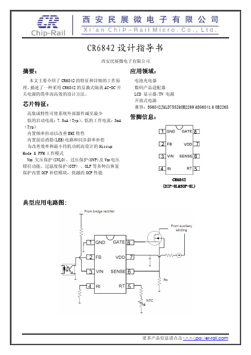
图 1.1 CR6842 内部框图
2.欠压锁定和启动电路及 OCP 补偿特性:
⑴、 CR6842 具有如下两种启动方式: 1) 传统的启动方式:使用 VDD 作启动脚时芯片支持从整流前启动及整流滤波后启动的方式,其 启动电路见图 1.2.1,图 1.2.1 所示; 2) 具有 OCP 补偿功能的启动方式:使用 3 脚 VIN 作启动脚时芯片具有 OCP 补偿的功能,但仅 支持从整流滤波后启动的方式,其启动电路方式见图 1.2.3 典型电路。
假设光耦的最大传输比ctr08系统二次侧次级tl431的工作电流仅由流过光耦发射端二极管的电流提供那么通过ic折算到流过光耦发射端二极管的电流最大仅为063ma这个电流将无法满足tl431的最小工作电流1ma所以在系统设计时使用cr6842设计的系统必须给次级tl431提供一个常态偏置电阻见图25电路中的rbias使tl431工作在正常的状态否则系统的负载调整率或其他性能可能会发生异常在16v输出的系统中考虑空载或轻载时系统的损耗因素推荐使用的偏置电阻阻值为22k
2)、影响 OCP 补偿平坦度的主要参数: 频率:基于 50KHZ~65KHz 设计。 启动电阻:基于 1.8MΩ 设计。 Sense 端输入:基于省掉外部 R-C 网络设计,见 Sense 端输入的说明。
3)、Sense 端口门限与 VIN 端口输入电流的关系曲线图
从图中可以看到,如果系统设计以 VIN 端口(3 脚)作为启动端,那么 VTH_oc 的值是受流过 VIN 端的 电流影响的,熟悉 Sense 端门限与 VIN 端输入电流的关系曲线图对分析系统的 OCP 特性是有帮助的。
《半导体器件物理专题HEMT》PPT课件讲义
三.HEMT的应用
Applications are similar to those of MESFETs – microwave and millimeter wave communications, imaging, radar, and radio astronomy – any application where high gain and low noise at high frequencies are required. HEMTs have shown current gain to frequencies greater than 600 GHz and power gain to frequencies greater than 1 THz. (Heterojunction bipolar transistors were demonstrated at current gain frequencies over 600 GHz in April 2005.) Numerous companies worldwide develop and manufacture HEMT-based devices. These can be discrete transistors but are more usually in the form of a 'monolithic microwave integrated circuit' (MMIC). HEMTs are found in many types of equipment ranging from cell-phones and DBS receivers to electronic warfare systems such as radar and for radio astronomy.
TDA8920B中文资料
TDA8920BJ DBS23P plastic DIL-bent-SIL power package; 23 leads (straight lead length 3.2 mm)
Version SOT566-3
SOT411-1
9397 750 13356
Preliminary data sheet
9397 750 13356
Preliminary data sheet
Rev. 01 — 1 October 2004
© Koninklijke Philips Electronics N.V. 2004. All rights reserved.
3 of 34
Philips Semiconductors
2 × 100 W class-D power amplifier
4. Quick reference data
Table 1: Quick refere
Conditions
General; VP = ±27 V
VP
supply voltage
Iq(tot)
total quiescent supply current
no load; no filter; no RC-snubber network connected
Stereo single-ended configuration
Po
output power RL = 3 Ω; THD = 10 %; VP = ±27 V
DRIVER LOW
TEMPERATURE SENSOR CURRENT PROTECTION VOLTAGE PROTECTION
TDA8920BTH (TDA8920BJ)
集成电路器件工艺
材料工艺元件电路形式电路规模Si Si-Bipolar D, BJT, R, C, L TTL,ECL,CML LSI NMOS D,NMOS,R,C NMOS,SCL VLSI CMOS D,P/N-NMOS,R,C,L CMOS,SCL ULSI,GSI BiCMOS D, BJT, P/N-NMOS,R,C, L ECL,CMOS VLSI,ULSI 第四章集成电路器件工艺1Ge BiCMOS D, HBT, P/N-NMOS,R,C, L ECL/SCL,CMOS LSI,VLSIGaAs MESFET D,LD,PD,MESFET,R,C, L SCL LSI,VLSI HEMT D,LD,PD,HEMT,R,C, L SCL LSI,VLSI HBT D,LD,PD,HBT,R,C, L ECL,CML MSI,LSIInP HEMT D,LD,PD,HEMT,R,C, L SCL,CML MSI HBT D,LD,PD,HBT,R,C, L ECL,CML MSI几种IC工艺速度功耗区位图24.1 双极型集成电路的基本制造工艺4.2 MESFET和HEMT工艺4.3 MOS工艺和相关的VLSI工艺4.4BiCMOS工艺34.1.1双极型硅工艺N +N +SiO 2BE C Metal PN-Isolation PN-Isolation P 12双极型硅的高速度、高跨导、低噪声及阈值易控制的特性,在高速数字通信系统中有着广泛的应用。
比较典型的有低噪声高灵敏度放大器、微分电路、振荡器等。
4N +Buried LayerP-图4.2P +N -P +3早期的双极型硅工艺:NPN 三极管1. B-E 结与基极接触孔之间的P 型区域而形成较大的基区体电阻2. 集电极接触孔下N 区域导致较大的集电极串联电阻3. 因PN 结隔离而形成较大的集电极寄生电容先进的双极型硅工晶体管水平与垂直尺寸减小:最短的发射极线宽小于0.5um,发射区与基区扩散深度和发射区下基区的厚度都小于100nm 。
稳定的高功率激光系统在高级引力波探测器中的应用
Stabilized high-power laser system forthe gravitational wave detector advancedLIGOP.Kwee,1,∗C.Bogan,2K.Danzmann,1,2M.Frede,4H.Kim,1P.King,5J.P¨o ld,1O.Puncken,3R.L.Savage,5F.Seifert,5P.Wessels,3L.Winkelmann,3and B.Willke21Max-Planck-Institut f¨u r Gravitationsphysik(Albert-Einstein-Institut),Hannover,Germany2Leibniz Universit¨a t Hannover,Hannover,Germany3Laser Zentrum Hannover e.V.,Hannover,Germany4neoLASE GmbH,Hannover,Germany5LIGO Laboratory,California Institute of Technology,Pasadena,California,USA*patrick.kwee@aei.mpg.deAbstract:An ultra-stable,high-power cw Nd:Y AG laser system,devel-oped for the ground-based gravitational wave detector Advanced LIGO(Laser Interferometer Gravitational-Wave Observatory),was comprehen-sively ser power,frequency,beam pointing and beamquality were simultaneously stabilized using different active and passiveschemes.The output beam,the performance of the stabilization,and thecross-coupling between different stabilization feedback control loops werecharacterized and found to fulfill most design requirements.The employedstabilization schemes and the achieved performance are of relevance tomany high-precision optical experiments.©2012Optical Society of AmericaOCIS codes:(140.3425)Laser stabilization;(120.3180)Interferometry.References and links1.S.Rowan and J.Hough,“Gravitational wave detection by interferometry(ground and space),”Living Rev.Rel-ativity3,1–3(2000).2.P.R.Saulson,Fundamentals of Interferometric Gravitational Wave Detectors(World Scientific,1994).3.G.M.Harry,“Advanced LIGO:the next generation of gravitational wave detectors,”Class.Quantum Grav.27,084006(2010).4. B.Willke,“Stabilized lasers for advanced gravitational wave detectors,”Laser Photon.Rev.4,780–794(2010).5.P.Kwee,“Laser characterization and stabilization for precision interferometry,”Ph.D.thesis,Universit¨a t Han-nover(2010).6.K.Somiya,Y.Chen,S.Kawamura,and N.Mio,“Frequency noise and intensity noise of next-generationgravitational-wave detectors with RF/DC readout schemes,”Phys.Rev.D73,122005(2006).7. B.Willke,P.King,R.Savage,and P.Fritschel,“Pre-stabilized laser design requirements,”internal technicalreport T050036-v4,LIGO Scientific Collaboration(2009).8.L.Winkelmann,O.Puncken,R.Kluzik,C.Veltkamp,P.Kwee,J.Poeld,C.Bogan,B.Willke,M.Frede,J.Neu-mann,P.Wessels,and D.Kracht,“Injection-locked single-frequency laser with an output power of220W,”Appl.Phys.B102,529–538(2011).9.T.J.Kane and R.L.Byer,“Monolithic,unidirectional single-mode Nd:Y AG ring laser,”Opt.Lett.10,65–67(1985).10.I.Freitag,A.T¨u nnermann,and H.Welling,“Power scaling of diode-pumped monolithic Nd:Y AG lasers to outputpowers of several watts,”mun.115,511–515(1995).11.M.Frede,B.Schulz,R.Wilhelm,P.Kwee,F.Seifert,B.Willke,and D.Kracht,“Fundamental mode,single-frequency laser amplifier for gravitational wave detectors,”Opt.Express15,459–465(2007).#161737 - $15.00 USD Received 18 Jan 2012; revised 27 Feb 2012; accepted 4 Mar 2012; published 24 Apr 2012 (C) 2012 OSA7 May 2012 / Vol. 20, No. 10 / OPTICS EXPRESS 1061712. A.D.Farinas,E.K.Gustafson,and R.L.Byer,“Frequency and intensity noise in an injection-locked,solid-statelaser,”J.Opt.Soc.Am.B12,328–334(1995).13.R.Bork,M.Aronsson,D.Barker,J.Batch,J.Heefner,A.Ivanov,R.McCarthy,V.Sandberg,and K.Thorne,“New control and data acquisition system in the Advanced LIGO project,”Proc.of Industrial Control And Large Experimental Physics Control System(ICALEPSC)conference(2011).14.“Experimental physics and industrial control system,”/epics/.15.P.Kwee and B.Willke,“Automatic laser beam characterization of monolithic Nd:Y AG nonplanar ring lasers,”Appl.Opt.47,6022–6032(2008).16.P.Kwee,F.Seifert,B.Willke,and K.Danzmann,“Laser beam quality and pointing measurement with an opticalresonator,”Rev.Sci.Instrum.78,073103(2007).17. A.R¨u diger,R.Schilling,L.Schnupp,W.Winkler,H.Billing,and K.Maischberger,“A mode selector to suppressfluctuations in laser beam geometry,”Opt.Acta28,641–658(1981).18. B.Willke,N.Uehara,E.K.Gustafson,R.L.Byer,P.J.King,S.U.Seel,and R.L.Savage,“Spatial and temporalfiltering of a10-W Nd:Y AG laser with a Fabry-Perot ring-cavity premode cleaner,”Opt.Lett.23,1704–1706 (1998).19.J.H.P¨o ld,“Stabilization of the Advanced LIGO200W laser,”Diploma thesis,Leibniz Universit¨a t Hannover(2009).20. E.D.Black,“An introduction to Pound-Drever-Hall laser frequency stabilization,”Am.J.Phys.69,79–87(2001).21.R.W.P.Drever,J.L.Hall,F.V.Kowalski,J.Hough,G.M.Ford,A.J.Munley,and H.Ward,“Laser phase andfrequency stabilization using an optical resonator,”Appl.Phys.B31,97–105(1983).22. A.Bullington,ntz,M.Fejer,and R.Byer,“Modal frequency degeneracy in thermally loaded optical res-onators,”Appl.Opt.47,2840–2851(2008).23.G.Mueller,“Beam jitter coupling in Advanced LIGO,”Opt.Express13,7118–7132(2005).24.V.Delaubert,N.Treps,ssen,C.C.Harb,C.Fabre,m,and H.-A.Bachor,“TEM10homodynedetection as an optimal small-displacement and tilt-measurement scheme,”Phys.Rev.A74,053823(2006). 25.P.Kwee,B.Willke,and K.Danzmann,“Laser power noise detection at the quantum-noise limit of32A pho-tocurrent,”Opt.Lett.36,3563–3565(2011).26. A.Araya,N.Mio,K.Tsubono,K.Suehiro,S.Telada,M.Ohashi,and M.Fujimoto,“Optical mode cleaner withsuspended mirrors,”Appl.Opt.36,1446–1453(1997).27.P.Kwee,B.Willke,and K.Danzmann,“Shot-noise-limited laser power stabilization with a high-power photodi-ode array,”Opt.Lett.34,2912–2914(2009).28. ntz,P.Fritschel,H.Rong,E.Daw,and G.Gonz´a lez,“Quantum-limited optical phase detection at the10−10rad level,”J.Opt.Soc.Am.A19,91–100(2002).1.IntroductionInterferometric gravitational wave detectors[1,2]perform one of the most precise differential length measurements ever.Their goal is to directly detect the faint signals of gravitational waves emitted by astrophysical sources.The Advanced LIGO(Laser Interferometer Gravitational-Wave Observatory)[3]project is currently installing three second-generation,ground-based detectors at two observatory sites in the USA.The4kilometer-long baseline Michelson inter-ferometers have an anticipated tenfold better sensitivity than theirfirst-generation counterparts (Inital LIGO)and will presumably reach a strain sensitivity between10−24and10−23Hz−1/2.One key technology necessary to reach this extreme sensitivity are ultra-stable high-power laser systems[4,5].A high laser output power is required to reach a high signal-to-quantum-noise ratio,since the effect of quantum noise at high frequencies in the gravitational wave readout is reduced with increasing circulating laser power in the interferometer.In addition to quantum noise,technical laser noise coupling to the gravitational wave channel is a major noise source[6].Thus it is important to reduce the coupling of laser noise,e.g.by optical design or by exploiting symmetries,and to reduce laser noise itself by various active and passive stabilization schemes.In this article,we report on the pre-stabilized laser(PSL)of the Advanced LIGO detector. The PSL is based on a high-power solid-state laser that is comprehensively stabilized.One laser system was set up at the Albert-Einstein-Institute(AEI)in Hannover,Germany,the so called PSL reference system.Another identical PSL has already been installed at one Advanced LIGO site,the one near Livingston,LA,USA,and two more PSLs will be installed at the second #161737 - $15.00 USD Received 18 Jan 2012; revised 27 Feb 2012; accepted 4 Mar 2012; published 24 Apr 2012 (C) 2012 OSA7 May 2012 / Vol. 20, No. 10 / OPTICS EXPRESS 10618site at Hanford,WA,USA.We have characterized the reference PSL and thefirst observatory PSL.For this we measured various beam parameters and noise levels of the output beam in the gravitational wave detection frequency band from about10Hz to10kHz,measured the performance of the active and passive stabilization schemes,and determined upper bounds for the cross coupling between different control loops.At the time of writing the PSL reference system has been operated continuously for more than18months,and continues to operate reliably.The reference system delivered a continuous-wave,single-frequency laser beam at1064nm wavelength with a maximum power of150W with99.5%in the TEM00mode.The active and passive stabilization schemes efficiently re-duced the technical laser noise by several orders of magnitude such that most design require-ments[5,7]were fulfilled.In the gravitational wave detection frequency band the relative power noise was as low as2×10−8Hz−1/2,relative beam pointingfluctuations were as low as1×10−7Hz−1/2,and an in-loop measurement of the frequency noise was consistent with the maximum acceptable frequency noise of about0.1HzHz−1/2.The cross couplings between the control loops were,in general,rather small or at the expected levels.Thus we were able to optimize each loop individually and observed no instabilities due to cross couplings.This stabilized laser system is an indispensable part of Advanced LIGO and fulfilled nearly all design goals concerning the maximum acceptable noise levels of the different beam pa-rameters right after installation.Furthermore all or a subset of the implemented stabilization schemes might be of interest for many other high-precision optical experiments that are limited by laser noise.Besides gravitational wave detectors,stabilized laser systems are used e.g.in the field of optical frequency standards,macroscopic quantum objects,precision spectroscopy and optical traps.In the following section the laser system,the stabilization scheme and the characterization methods are described(Section2).Then,the results of the characterization(Section3)and the conclusions(Section4)are presented.ser system and stabilizationThe PSL consists of the laser,developed and fabricated by Laser Zentrum Hannover e.V.(LZH) and neoLASE,and the stabilization,developed and integrated by AEI.The optical components of the PSL are on a commercial optical table,occupying a space of about1.5×3.5m2,in a clean,dust-free environment.At the observatory sites the optical table is located in an acoustically isolated cleanroom.Most of the required electronics,the laser diodes for pumping the laser,and water chillers for cooling components on the optical table are placed outside of this cleanroom.The laser itself consists of three stages(Fig.1).An almostfinal version of the laser,the so-called engineering prototype,is described in detail in[8].The primary focus of this article is the stabilization and characterization of the PSL.Thus only a rough overview of the laser and the minor modifications implemented between engineering prototype and reference system are given in the following.Thefirst stage,the master laser,is a commercial non-planar ring-oscillator[9,10](NPRO) manufactured by InnoLight GmbH in Hannover,Germany.This solid-state laser uses a Nd:Y AG crystal as the laser medium and resonator at the same time.The NPRO is pumped by laser diodes at808nm and delivers an output power of2W.An internal power stabilization,called the noise eater,suppresses the relaxation oscillation at around1MHz.Due to its monolithic res-onator,the laser has exceptional intrinsic frequency stability.The two subsequent laser stages, used for power scaling,inherit the frequency stability of the master laser.The second stage(medium-power amplifier)is a single-pass amplifier[11]with an output power of35W.The seed laser beam from the NPRO stage passes through four Nd:YVO4crys-#161737 - $15.00 USD Received 18 Jan 2012; revised 27 Feb 2012; accepted 4 Mar 2012; published 24 Apr 2012 (C) 2012 OSA7 May 2012 / Vol. 20, No. 10 / OPTICS EXPRESS 10619power stabilizationFig.1.Pre-stabilized laser system of Advanced LIGO.The three-staged laser(NPRO,medium power amplifier,high power oscillator)and the stabilization scheme(pre-mode-cleaner,power and frequency stabilization)are shown.The input-mode-cleaner is not partof the PSL but closely related.NPRO,non-planar ring oscillator;EOM,electro-optic mod-ulator;FI,Faraday isolator;AOM,acousto-optic modulator.tals which are longitudinally pumped byfiber-coupled laser diodes at808nm.The third stage is an injection-locked ring oscillator[8]with an output power of about220W, called the high-power oscillator(HPO).Four Nd:Y AG crystals are used as the active media. Each is longitudinally pumped by sevenfiber-coupled laser diodes at808nm.The oscillator is injection-locked[12]to the previous laser stage using a feedback control loop.A broadband EOM(electro-optic modulator)placed between the NPRO and the medium-power amplifier is used to generate the required phase modulation sidebands at35.5MHz.Thus the high output power and good beam quality of this last stage is combined with the good frequency stability of the previous stages.The reference system features some minor modifications compared to the engineering proto-type[8]concerning the optics:The external halo aperture was integrated into the laser system permanently improving the beam quality.Additionally,a few minor designflaws related to the mechanical structure and the optical layout were engineered out.This did not degrade the output performance,nor the characteristics of the locked laser.In general the PSL is designed to be operated in two different power modes.In high-power mode all three laser stages are engaged with a power of about160W at the PSL output.In low-power mode the high-power oscillator is turned off and a shutter inside the laser resonator is closed.The beam of the medium-power stage is reflected at the output coupler of the high power stage leaving a residual power of about13W at the PSL output.This low-power mode will be used in the early commissioning phase and in the low-frequency-optimized operation mode of Advanced LIGO and is not discussed further in this article.The stabilization has three sections(Fig.1:PMC,PD2,reference cavity):A passive resonator, the so called pre-mode-cleaner(PMC),is used tofilter the laser beam spatially and temporally (see subsection2.1).Two pick-off beams at the PMC are used for the active power stabilization (see subsection2.2)and the active frequency pre-stabilization,respectively(see subsection2.3).In general most stabilization feedback control loops of the PSL are implemented using analog electronics.A real-time computer system(Control and Data Acquisition Systems,CDS,[13]) which is common to many other subsystems of Advanced LIGO,is utilized to control and mon-itor important parameters of the analog electronics.The lock acquisition of various loops,a few #161737 - $15.00 USD Received 18 Jan 2012; revised 27 Feb 2012; accepted 4 Mar 2012; published 24 Apr 2012 (C) 2012 OSA7 May 2012 / Vol. 20, No. 10 / OPTICS EXPRESS 10620slow digital control loops,and the data acquisition are implemented using this computer sys-tem.Many signals are recorded at different sampling rates ranging from16Hz to33kHz for diagnostics,monitoring and vetoing of gravitational wave signals.In total four real-time pro-cesses are used to control different aspects of the laser system.The Experimental Physics and Industrial Control System(EPICS)[14]and its associated user tools are used to communicate with the real-time software modules.The PSL contains a permanent,dedicated diagnostic instrument,the so called diagnostic breadboard(DBB,not shown in Fig.1)[15].This instrument is used to analyze two different beams,pick-off beams of the medium power stage and of the HPO.Two shutters are used to multiplex these to the DBB.We are able to measurefluctuations in power,frequency and beam pointing in an automated way with this instrument.In addition the beam quality quantified by the higher order mode content of the beam was measured using a modescan technique[16].The DBB is controlled by one real-time process of the CDS.In contrast to most of the other control loops in the PSL,all DBB control loops were implemented digitally.We used this instrument during the characterization of the laser system to measure the mentioned laser beam parameters of the HPO.In addition we temporarily placed an identical copy of the DBB downstream of the PMC to characterize the output beam of the PSL reference system.2.1.Pre-mode-cleanerA key component of the stabilization scheme is the passive ring resonator,called the pre-mode-cleaner(PMC)[17,18].It functions to suppress higher-order transverse modes,to improve the beam quality and the pointing stability of the laser beam,and tofilter powerfluctuations at radio frequencies.The beam transmitted through this resonator is the output beam of the PSL, and it is delivered to the subsequent subsystems of the gravitational wave detector.We developed and used a computer program[19]to model thefilter effects of the PMC as a function of various resonator parameters in order to aid its design.This led to a resonator with a bow-tie configuration consisting of four low-loss mirrors glued to an aluminum spacer. The optical round-trip length is2m with a free spectral range(FSR)of150MHz.The inci-dence angle of the horizontally polarized laser beam is6◦.Theflat input and output coupling mirrors have a power transmission of2.4%and the two concave high reflectivity mirrors(3m radius of curvature)have a transmission of68ppm.The measured bandwidth was,as expected, 560kHz which corresponds to afinesse of133and a power build-up factor of42.The Gaussian input/output beam had a waist radius of about568µm and the measured acquired round-trip Gouy phase was about1.7rad which is equivalent to0.27FSR.One TEM00resonance frequency of the PMC is stabilized to the laser frequency.The Pound-Drever-Hall(PDH)[20,21]sensing scheme is used to generate error signals,reusing the phase modulation sidebands at35.5MHz created between NPRO and medium power amplifier for the injection locking.The signal of the photodetector PD1,placed in reflection of the PMC, is demodulated at35.5MHz.This photodetector consists of a1mm InGaAs photodiode and a transimpedance amplifier.A piezo-electric element(PZT)between one of the curved mirrors and the spacer is used as a fast actuator to control the round-trip length and thereby the reso-nance frequencies of the PMC.With a maximum voltage of382V we were able to change the round-trip length by about2.4µm.An analog feedback control loop with a bandwidth of about 7kHz is used to stabilize the PMC resonance frequency to the laser frequency.In addition,the electronics is able to automatically bring the PMC into resonance with the laser(lock acquisition).For this process a125ms period ramp signal with an amplitude cor-responding to about one FSR is applied to the PZT of the PMC.The average power on pho-todetector PD1is monitored and as soon as the power drops below a given threshold the logic considers the PMC as resonant and closes the analog control loop.This lock acquisition proce-#161737 - $15.00 USD Received 18 Jan 2012; revised 27 Feb 2012; accepted 4 Mar 2012; published 24 Apr 2012 (C) 2012 OSA7 May 2012 / Vol. 20, No. 10 / OPTICS EXPRESS 10621dure took an average of about65ms and is automatically repeated as soon as the PMC goes off resonance.One real-time process of CDS is dedicated to control the PMC electronics.This includes parameters such as the proportional gain of the loop or lock acquisition parameters.In addition to the PZT actuator,two heating foils,delivering a maximum total heating power of14W,are attached to the aluminum spacer to control its temperature and thereby the roundtrip length on timescales longer than3s.We measured a heating and cooling1/e time constant of about2h with a range of4.5K which corresponds to about197FSR.During maintenance periods we heat the spacer with7W to reach a spacer temperature of about2.3K above room temperature in order to optimize the dynamic range of this actuator.A digital control loop uses this heater as an actuator to off-load the PZT actuator allowing compensation for slow room temperature and laser frequency drifts.The PMC is placed inside a pressure-tight tank at atmospheric pressure for acoustic shield-ing,to avoid contamination of the resonator mirrors and to minimize optical path length changes induced by atmospheric pressure variations.We used only low-outgassing materials and fabri-cated the PMC in a cleanroom in order to keep the initial mirror contamination to a minimum and to sustain a high long-term throughput.The PMCfilters the laser beam and improves the beam quality of the laser by suppress-ing higher order transverse modes[17].The acquired round-trip Gouy phase of the PMC was chosen in such a way that the resonance frequencies of higher order TEM modes are clearly separated from the TEM00resonance frequency.Thus these modes are not resonant and are mainly reflected by the PMC,whereas the TEM00mode is transmitted.However,during the design phase we underestimated the thermal effects in the PMC such that at nominal circu-lating power the round-trip Gouy-phase is close to0.25FSR and the resonance of the TEM40 mode is close to that of the TEM00mode.To characterize the mode-cleaning performance we measured the beam quality upstream and downstream of the PMC with the two independent DBBs.At150W in the transmitted beam,the circulating power in the PMC is about6.4kW and the intensity at the mirror surface can be as high as1.8×1010W m−2.At these power levels even small absorptions in the mirror coatings cause thermal effects which slightly change the mirror curvature[22].To estimate these thermal effects we analyzed the transmitted beam as a function of the circulating power using the DBB.In particular we measured the mode content of the LG10and TEM40mode.Changes of the PMC eigenmode waist size showed up as variations of the LG10mode content.A power dependence of the round-trip Gouy phase caused a variation of the power within the TEM40mode since its resonance frequency is close to a TEM00mode resonance and thus the suppression of this mode depends strongly on the Gouy phase.We adjusted the input power to the PMC such that the transmitted power ranged from100W to 150W corresponding to a circulating power between4.2kW and6.4kW.We used our PMC computer simulation to deduce the power dependence of the eigenmode waist size and the round-trip Gouy phase.The results are given in section3.1.At all circulating power levels,however,the TEM10and TEM01modes are strongly sup-pressed by the PMC and thus beam pointingfluctuations are reduced.Pointingfluctuations can be expressed tofirst order as powerfluctuations of the TEM10and TEM01modes[23,24].The PMC reduces thefield amplitude of these modes and thus the pointingfluctuations by a factor of about61according to the measuredfinesse and round-trip Gouy phase.To keep beam point-ingfluctuations small is important since they couple to the gravitational wave channel by small differential misalignments of the interferometer optics.Thus stringent design requirements,at the10−6Hz−1/2level for relative pointing,were set.To verify the pointing suppression effect of the PMC we used DBBs to measure the beam pointingfluctuations upstream and downstream #161737 - $15.00 USD Received 18 Jan 2012; revised 27 Feb 2012; accepted 4 Mar 2012; published 24 Apr 2012 (C) 2012 OSA7 May 2012 / Vol. 20, No. 10 / OPTICS EXPRESS 10622Fig.2.Detailed schematic of the power noise sensor setup for thefirst power stabilizationloop.This setup corresponds to PD2in the overview in Fig.1.λ/2,waveplate;PBS,polar-izing beam splitter;BD,glassfilters used as beam dump;PD,single element photodetector;QPD,quadrant photodetector.of the PMC.The resonator design has an even number of nearly normal-incidence reflections.Thus the resonance frequencies of horizontal and vertical polarized light are almost identical and the PMC does not act as polarizer.Therefore we use a thin-film polarizer upstream of the PMC to reach the required purity of larger than100:1in horizontal polarization.Finally the PMC reduces technical powerfluctuations at radio frequencies(RF).A good power stability between9MHz and100MHz is necessary as the phase modulated light in-jected into the interferometer is used to sense several degrees of freedom of the interferometer that need to be controlled.Power noise around these phase modulation sidebands would be a noise source for the respective stabilization loop.The PMC has a bandwidth(HWHM)of about 560kHz and acts tofirst order as a low-passfilter for powerfluctuations with a-3dB corner frequency at this frequency.To verify that the suppression of RF powerfluctuations is suffi-cient to fulfill the design requirements,we measured the relative power noise up to100MHz downstream of the PMC with a dedicated experiment involving the optical ac coupling tech-nique[25].In addition the PMC serves the very important purpose of defining the spatial laser mode for the downstream subsystem,namely the input optics(IO)subsystem.The IO subsystem is responsible,among other things,to further stabilize the laser beam with the suspended input mode cleaner[26]before the beam will be injected into the interferometer.Modifications of beam alignment or beam size of the laser system,which were and might be unavoidable,e.g., due to maintenance,do not propagate downstream of the PMC tofirst order due to its mode-cleaning effect.Furthermore we benefit from a similar isolating effect for the active power and frequency stabilization by using the beams transmitted through the curved high-reflectivity mirrors of the PMC.2.2.Power stabilizationThe passivefiltering effect of the PMC reduces powerfluctuations significantly only above the PMC bandwidth.In the detection band from about10Hz to10kHz good power stability is required sincefluctuations couple via the radiation pressure imbalance and the dark-fringe offset to the gravitational wave channel.Thus two cascaded active control loops,thefirst and second power stabilization loop,are used to reduce powerfluctuations which are mainly caused by the HPO stage.Thefirst loop uses a low-noise photodetector(PD2,see Figs.1and2)at one pick-off port #161737 - $15.00 USD Received 18 Jan 2012; revised 27 Feb 2012; accepted 4 Mar 2012; published 24 Apr 2012 (C) 2012 OSA7 May 2012 / Vol. 20, No. 10 / OPTICS EXPRESS 10623of the PMC to measure the powerfluctuations downstream of the PMC.An analog electronics feedback control loop and an AOM(acousto-optic modulator)as actuator,located upstream of the PMC,are used to stabilize the power.Scattered light turned out to be a critical noise source for thisfirst loop.Thus we placed all required optical and opto-electronic components into a box to shield from scattered light(see Fig.2).The beam transmitted by the curved PMC mirror has a power of about360mW.This beam isfirst attenuated in the box using aλ/2waveplate and a thin-film polarizer,such that we are able to adjust the power on the photodetectors to the optimal operation point.Afterwards the beam is split by a50:50beam splitter.The beams are directed to two identical photode-tectors,one for the control loop(PD2a,in-loop detector)and one for independent out-of-loop measurements to verify the achieved power stability(PD2b,out-of-loop detector).These pho-todetectors consist of a2mm InGaAs photodiode(PerkinElmer C30642GH),a transimpedance amplifier and an integrated signal-conditioningfilter.At the chosen operation point a power of about4mW illuminates each photodetector generating a photocurrent of about3mA.Thus the shot noise is at a relative power noise of10−8Hz−1/2.The signal conditioningfilter has a gain of0.2at very low frequencies(<70mHz)and amplifies the photodetector signal in the im-portant frequency range between3.3Hz and120Hz by about52dB.This signal conditioning filter reduces the electronics noise requirements on all subsequent stages,but has the drawback that the range between3.3Hz and120Hz is limited to maximum peak-to-peak relative power fluctuations of5×10−3.Thus the signal-conditioned channel is in its designed operation range only when the power stabilization loop is closed and therefore it is not possible to measure the free running power noise using this channel due to saturation.The uncoated glass windows of the photodiodes were removed and the laser beam hits the photodiodes at an incidence angle of45◦.The residual reflection from the photodiode surface is dumped into a glassfilter(Schott BG39)at the Brewster angle.Beam positionfluctuations in combination with spatial inhomogeneities in the photodiode responsivity is another noise source for the power stabilization.We placed a silicon quadrant photodetector(QPD)in the box to measure the beam positionfluctuations of a low-power beam picked off the main beam in the box.The beam parameters,in particular the Gouy phase,at the QPD are the same as on the power sensing detectors.Thus the beam positionfluctuations measured with the QPD are the same as the ones on the power sensing photodetectors,assuming that the positionfluctuations are caused upstream of the QPD pick-off point.We used the QPD to measure beam positionfluctuations only for diagnostic and noise projection purposes.In a slightly modified experiment,we replaced one turning mirror in the path to the power sta-bilization box by a mirror attached to a tip/tilt PZT element.We measured the typical coupling between beam positionfluctuations generated by the PZT and the residual relative photocurrent fluctuations measured with the out-of-the-loop photodetector.This coupling was between1m−1 and10m−1which is a typical value observed in different power stabilization experiments as well.We measured this coupling factor to be able to calculate the noise contribution in the out-of-the-loop photodetector signal due to beam positionfluctuations(see Subsection3.3).Since this tip/tilt actuator was only temporarily in the setup,we are not able to measure the coupling on a regular basis.Both power sensing photodetectors are connected to analog feedback control electronics.A low-pass(100mHz corner frequency)filtered reference value is subtracted from one signal which is subsequently passed through several control loopfilter stages.With power stabilization activated,we are able to control the power on the photodetectors and thereby the PSL output power via the reference level on time scales longer than10s.The reference level and other important parameters of these electronics are controlled by one dedicated real-time process of the CDS.The actuation or control signal of the electronics is passed to an AOM driver #161737 - $15.00 USD Received 18 Jan 2012; revised 27 Feb 2012; accepted 4 Mar 2012; published 24 Apr 2012 (C) 2012 OSA7 May 2012 / Vol. 20, No. 10 / OPTICS EXPRESS 10624。