SFZ-80-JJH(S)型进近灯说明书
进近灯光系统

进近灯光系统进近灯光系统(ALS)一般安装在机场跑道进近端及跑道延伸处,通常用于仪表进近程序(IAP)。
经过多年发展,现在的进近灯光系统设计上已经更全面和完善,可以极大的提高飞机运行安全尤其是低能见度条件下的运行。
以下给大家简要介绍几种咱们常见的进近灯光系统1.简易进近灯光系统(SALS)简易进近灯光系统应由一行位于跑道中线延长线上并尽可能延伸到跑道入口不小于420m处的灯具和一排在距跑道入口300m处构成一个长30m或18m的横排灯的灯具组成。
2.I类进近灯光系统Ⅰ类精密进近灯光系统的全长应延伸到距跑道入口900 m,因场地条件限制无法满足上述要求时可以适当缩短,但总长度不得低于720 m。
Ⅰ类精密进近灯光系统应由一行位于跑道中线延长线上并尽可能延伸到距跑道入口900 m处的中线灯和一排在距跑道入口300 m 处构成一个长30 m的横排灯组成。
3. II/III类进近灯光系统Ⅱ类或Ⅲ类精密进近跑道应设Ⅱ、Ⅲ类精密进近灯光系统。
Ⅱ、Ⅲ类精密进近灯光系统全长宜为900 m,因场地条件限制无法满足上述要求时可以适当缩短,但总长度不得低于720 m。
应由一行位于跑道中线延长线上并尽可能延伸到距跑道入口900 m处的灯具组成,此外还应有两行延伸到距跑道入口270 m处的边灯以及两排横排灯,一排距跑道入口150 m,另一排距跑道入口300 m。
上述的进近灯光是咱们常见的三种类型,他们是各种灯光组合而成的灯光系统。
其中,跑道中线灯、进近横排灯、进近旁线灯、目视进近坡度指示系统及精密进近航道指示器为进近灯光系统的主要组成部分。
下面就给大家简介一下这几种灯光。
1.进近中线灯这些灯一般以5米、7米、15米或30米的纵向间隔均匀排列,从跑道入口至末端标出跑道中线。
从跑道入口到离跑道末端900米处,是可变白色的固定灯;由距跑道末端900米处到离跑道末端300米处,是红色与可变白色相间;由离跑道末端300米处直到跑道末端为红色。
FJ Westcott FJ80 II Speedlight说明书

SPEEDLIGHTSQUICK START GUIDEVisit /firmware to download the latest firmwareIncluded Components & OverviewFJ80 II Speedlight, FJ80 II Lithium Polymer Battery, Battery Charger, Shoe Stand, USB-A to USB-C Cable, Travel CaseMain MenuLanguage English DECIMAL Display OK Factory Reset Page 3/3Canon Nikon Sony FujiOlympuLumixVersion Page 1/3 1.0Screen 21.5OFF ON ON 00Auto-Off X-Sync Beep ON Freeze RT ID#OK Settings MenuVersion Page 2/31.0AF BeamAUTOLanguage EnglishDECIMALDisplay OKFactory ResetVersion Page 1/31.0Screen 21.5OFF ONON 00Auto-Off X-Sync BeepONFreezeRT ID#OKSettings MenuSpeedlight MenuA Camera Brand Selection,Sync Function SelectionB Flash Mode Icon, Lock Icon, Battery Icon Indicator CPower Output Value / FEC ±3D Mode Selection, Zoom Selection, Modeling Lamp SettingESelection Control Arrows, OK ButtonClient MenuA FJ Wireless Enabled, ChannelSelection, Group SelectionB Flash Mode Icon, Lock Icon, Battery Icon IndicatorC Power Output Value / FEC ±3D Sync Function IconE Mode Selection, Zoom Selection, Modeling Lamp SettingFSelection Control Arrows, OK ButtonHost MenuA Camera Brand Selection, Channel Selection, Group SelectionB Lock Icon, Battery IconIndicatorCTTL / M Group Designations, Power Output Value / FEC ±3, Modeling Lamp Control D Sync Function Selection, Zoom Selection, Host Speedlight Enable/Disable ESelection Control Arrows, OK ButtonIntroductionThis guide covers setup, controls, and basic operation.Visit /documentation and scroll to the Supportsection to download the complete FJ80 II User Manual.Warning• IMPORTANT: During operation, the temperature of the speedlight lens and various components of the F J80 II speedlight may increase. Please use caution while using to avoid severe burns or injuries.• Use only with the Westcott F J80 II Lithium Polymer Battery and Charger.• Do not touch the speedlight lens after immediate use to avoid potential injury.• Never leave unattended around children and/or pets.• Always confirm proper installation, locking, and unlocking when adding or removing from the camera hot shoe. Failure to completely rotate could result in damaging the locking pin.• Keep away from fire, water, and moisture.• Do not submerge in water.• Avoid drastic temperature changes before, during, or after use.• Always remove the F J80 II Lithium Polymer Battery from the F J80 II Speedlight during travel/ storage to avoid accidental operation, which could lead to overheating or permanent damage.• Do not force adjust or add excessive weight to the speedlight head.• Only use the F J80 II Speedlight with F J80 Series compatible mounts, brackets, modifiers and/or accessories.• Do not attempt to modify any Westcott products. Contact Westcott for assistance.• The maximum operating temperature is 14~122°F (-10~50°C).Dual-Stage Heat ProtectionThe F J80 II is equipped with a self-monitoring system ensuring safe operation during continued full-power use during a short timeframe. The monitoring system provides a staged automatic protection scenario;• Stage 1: Once the speedlight reaches an internal operating temperature of 212°F (100°C), the screen will display a yellow OH. The recycle time will also increase to 2 seconds in efforts to cool the unit while allowing for further operation.• Stage 2: Once the strobe reaches an internal operating temperature of 266°F (130°C), the screen will display a red OH icon. The recycle time will increase an additional 2 seconds in efforts to cool the unit while allowing for further operation.• Once the unit has cooled, the red OH will disappear from the touchscreen, and it will then be safe to continue operation.Note: The LED modeling lamp will be disabled during OH in efforts to minimize heat.Getting StartedCharging the F J80 II Lithium Polymer Battery1. Ensure the F J80 II is OFF by long-pressing the Power button until the LCD screen turns off.2. Remove the battery from the F J80 II by pressing the two release buttons on the sides of thebattery and gently pull the battery away from the F J80 II battery port.3. Connect the USB-C Cord to the F J80 II Battery Charger and plug the AC adapter into a wall outlet.4. Align the metal contacts on the back of the FJ80 II battery with the contacts on the FJ80 IIcharger; while pressing the buttons on the side of the battery, gently insert the battery into the charger and gently press down until the battery locks into place.5. The battery is charged and can be safely removed from the charger when all of the LEDindicator lights turns green.6. Remove the battery from the charger by pressing the side release buttons and gently pullingaway from the charger.Battery Charger LED Indicator Light Colors:Green:• No Battery Inserted: One indicator illuminated green means the charger is plugged into a power outlet and ready to charge the F J80 II Li-po Battery.• Battery Inserted: The F J80 II Battery is fully-charged and ready to be removed from the charger. Orange:• Battery Inserted: The F J80 II Battery is correctly inserted and charging.Attaching the Lithium Polymer BatteryAttach the F J80 II Battery into the speedlight by aligning the metal contacts on the back of the battery to the contacts on the F J80 II battery port and gently press the battery into the port until it clicks into place.Powering On1. Ensure the F J80 II battery has been fully charged.2. Ensure the battery is securely attached to the F J80 II.3. Turn the speedlight ON by long-pressing the Power button, then tap the blue power logo on thescreen until the start-up screen appears.Note: The F J80 II LCD T ouchscreen is protected by a removable clear screen protector that can be removed at any time by gently pulling the film away from the display.MountingAttaching to a Camera or the Cold Shoe Stand1. Ensure the F J80 II is OFF and rotate the dial all the way to the right.2. Slide the F J80 II Speedlight base into the camera’s hot shoe or cold shoe stand with thetouchscreen facing the same direction as the rear of the camera or channel opening on the back of the shoe stand. (Note: Using the F J80 II M on Sony cameras REQUIRES the #4711 F J Adapter for Sony Cameras.)3. Rotate the Shoe Lock dial left until it’s securely mounted to the camera. Do not overtighten. Detaching from a Camera or the Cold Shoe Stand1. Ensure the F J80 II is OFF.2. Rotate the Shoe Lock dial left to right. (Note: Ensure that the dial has been completely movedto the right. Otherwise, the locking pin may be permanently damaged upon removal of thespeedlight.)3. Securely grasp the sides of the FJ80 II Speedlight, gently slide the speedlight towards the rearof the camera or cold shoe stand, and completely remove it from the camera’s hot shoe or cold shoe stand.Note: Never force or remove the F J80 II into or away from the camera’s hot shoe. Attaching & Removing ModifiersAttaching the F J80 II Magnetic Modifiers (Sold Separately)1. Ensure all modifiers have been removed and the F J80 II’s articulating flash head has cooled.2. Grasp the edges of the modifier’s magnetic ring, align the magnetic ring with the F J80 II’s face, andgently affix it into place. (Note: The magnetic ring may require a slight turn to ensure proper seating.)3.Remove the magnetic modifier by grasping the magnetic ring and pulling away from the speedlight head.F J80 Creative Pack#4755Diffusion Dome#47575" Reflector#4748Snoot with Honeycomb Grid#4746Magnetic Grid & Gel Pack#4758Updating FirmwareIMPORTANT• If the FJ80 II doesn’t display as an external device after connecting to a computer, disconnect the USB cable from both devices and restart the computer and firmware update process.• It’s recommended that the firmware update installation process be completed onlywhen the connected computer’s power level is ≥ 25%. Loss of power of any type during this process could render the FJ80 II inoperable and require professional repair.• Removing the USB cable from the FJ80 II without properly ejecting the device from your computer could render the trigger inoperable and require professional repair.• Copying the firmware from your computer to the FJ80 II may take a few minutes and/or halt the copying process. Should this happen, close the copy progress window and try again. Further copying issues may require the computer to be restarted.The FJ80 II is designed with a USB-C port to allow for firmware updates and charging. Future firmware updates may result in performance enhancements and modified menu options.The FJ80 II’s firmware version is displayed on the start-up screen. Please visit /firmware to update your FJ80 II to the latest firmware. Follow the instructions included with the firmware download to update.WarrantyWestcott’s warranty obligations for this product are limited to the following terms.The F.J. Westcott Co. (“Westcott”) warrants this Westcott branded product against defects in materials and workmanship under normal use for a period of ONE (1) YEAR from the date of retail purchase from Westcott or an authorized retailer by the original end-user purchaser (“Warranty Period”). If a defect arises and a valid claim is received within the Warranty Period, at its option and to the extent permitted by law, Westcott will either (1) repair the defect at no charge, using new or refurbished replacement parts, or (2) exchange the product with a product that is new or which has been manufactured from new or serviceable used partsand is at least functionally equivalent to the original product. This Limited Warranty applies only to products manufactured by or for Westcott that can be identified by the Westcott trademark, trade name, or logo affixed to them.This warranty does not apply to: (a) damage caused by accident, abuse, misuse, flood, fire, earthquake, mold, or other external causes; (b) damage caused by operating the product outside the permitted or intended uses described by Westcott; (c) a product or part that has been modified to alter functionality or capability without the written permission of Westcott; or (d) cosmetic damage, including but not limited to scratches, dents and broken plastic.Disclaimer: By purchasing, borrowing and/or using this product for any event, both public or private, you,the customer, accepts all responsibility and releases Westcott, and its associates, of any and all liability inthe event of manufacturer’s defect, malfunction or misuse of the product which may lead to further injuriesor complications unforeseen by the user. Westcott is not responsible for any potential or incurred damage caused by failure to properly mount, hang, or store the product, which includes, but is not limited to damage to cameras, electronics, electrical equipment, buildings, building materials, personal injury, death, or disability, fire damage, or any and all other damage not mentioned previously.Please contact Westcott Customer Support for a Return Authorization Number “RMA” prior to requesting warranty service. This RMA must be clearly written on the outside of the box to the left of the shipping label. Items sent in without pre-authorization or that do not fall under the limited warranty will be returned at the expense of the sender.Phone: 419-243-7311Email:**********************Shipping: F.J. Westcott Co, 1425-B Holland Rd. Maumee, OH 43537Visit for videos, pro tips, inspiration, and more!Westcott products are made to the company’s traditionally high standards of quality and comply withall applicable government safety regulations and requirements. In an effort to provide the best quality products possible, we periodically make product modifications. Actual products may not be identicalto items pictured. Made in China. ©F.J. Westcott Co. All rights reserved. J1022。
m80带灯版使用说明书
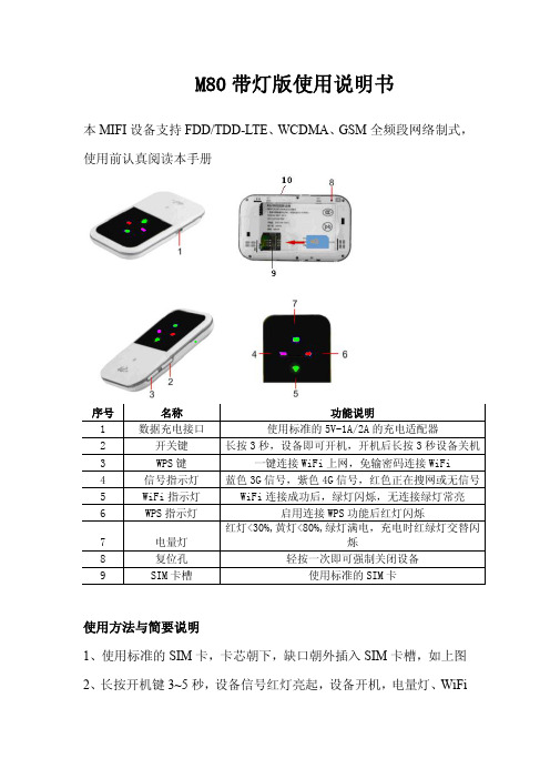
M80带灯版使用说明书本MIFI设备支持FDD/TDD-LTE、WCDMA、GSM全频段网络制式,使用前认真阅读本手册序号名称功能说明1数据充电接口使用标准的5V-1A/2A的充电适配器2开关键长按3秒,设备即可开机,开机后长按3秒设备关机3WPS键一键连接WiFi上网,免输密码连接WiFi4信号指示灯蓝色3G信号,紫色4G信号,红色正在搜网或无信号5WiFi指示灯WiFi连接成功后,绿灯闪烁,无连接绿灯常亮6WPS指示灯启用连接WPS功能后红灯闪烁7电量灯红灯<30%,黄灯<80%,绿灯满电,充电时红绿灯交替闪烁8复位孔轻按一次即可强制关闭设备9SIM卡槽使用标准的SIM卡使用方法与简要说明1、使用标准的SIM卡,卡芯朝下,缺口朝外插入SIM卡槽,如上图2、长按开机键3~5秒,设备信号红灯亮起,设备开机,电量灯、WiFi绿灯亮起,信号灯由红灯变为蓝灯或紫灯时,设备搜到网络信号即可连接本MIFI设备上网。
3、在手机、电脑等终端设备上搜索设备的WiFi名:4G MIFI-xxxx,输入密码1234567890连接即可。
4、在浏览器地址栏输入192.168.100.1:8080点确定进入后台网关登录界面,如下图5、后台管理后台网关界面——用户名、密码输入admin点登陆进入管理界面5.1、系统状态这里显示设备网络状态、基本信息、网络连接数量等5.2、家庭网络可以查看已连接的设备,控制上网设备5.3、无线无线设置:可以设置可连接设备的数量,设置后设备要重启后生效;首选网络——可以设置4G/3G/2G网络(需要设备支持,参照机身贴纸支持网络类型;SIM卡支持,由网络运营商提供,咨询当地网络提供商)无线安全设置:设置WiFi名称(SSID)、密码,点保存后生效。
无线MAC过滤:通过MAC地址控制连接网络的设备。
5.4、路由器设置网关登录密码、恢复出厂设置、关闭路由器、重启路由器等6、WPS一建上网功能打开手机或者电脑的WPS一建连接功能,以手机为例如下图,然后按动WPS键3秒,WPS指示红灯闪烁,启动设备WPS功能,自动连接WiFi上网。
800福立前照灯探测仪

FLG-800全自动远近光前照灯检测仪使用说明书V2.2广州市福立分析仪器有限公司广州市福立分析仪器有限公司佛山分公司地址:广东省广州市芳村浣花路109号地址:广东省佛山市禅城区轻工三路16号东鹏德宝商务中心9楼5—6单元 4号楼二层电话: (020)81501590 81615299 电话:(0757)82106910 88357166传真: (020)81615299 传真:(0757)82106910邮编: 510380 邮编:528000目录一、概述 (2)二、主要技术参数 (2)三、服务承诺及责任 (2)四、结构组成与作用 (3)五、安装 (5)六、面板功能与显示 (9)七、使用 (10)八、校准 (11)九、简单故障处理 (20)十、成套性 (21)十一、通讯说明 (21)一、概述FLG-800全自动前照灯检测仪(以下均简称“灯光仪”)是由高性能数字信号处理器(DSP6713)组成的视频信号处理及智能化控制系统。
其具有使用方便、测量准确、工作可靠、自动化程度高等优点,适用于机动车安全技术检测站对机动车前照灯的有关参数进行全自动检测,也适宜在机动车制造厂、维修厂对前照灯进行调整、检验时使用。
二、主要技术参数●测量范围发光强度:(0~60000)cd远光、近光光轴偏移量:(1)、垂直方向:上1°30´~下3°或上25cm/dam~下50cm/dam(2)、水平方向:左3°~右3°或左50cm/dam~右50cm/dam前照灯中心高:50cm~130cm●示值误差发光强度:±12%(相对误差)光轴角:±15´前照灯中心高:±1cm●间差:15´●检测距离:1m●消耗功率:约180W●使用条件环境温度:(0~40)℃相对温度:不大于90%大气压力:70.0kPa~106.0kPa电源电压:AC220V±22V电源频率:50Hz±1Hz三、服务承诺及责任3.1 质量保证承诺及责任用户自购买本产品一年内可免费保修享有广州市福立分析仪器有限公司提供的保修服务。
民航机场助航灯光系统

答案:a
解析:本题考查中线等级的纵向间距。中线灯具的纵向间距应为30m。
id415032跑道灯光系统的组成及安装位置
跑道灯光系统包括跑道入口识别灯、跑道入口灯和跑道入口翼排灯、跑道接地带灯、b
跑道中线灯、跑道边灯、跑道末端灯、停止道灯、跑道掉头坪灯,跑道侧的精密进近航道指示器(papi),风向标的照明灯,另外跑道上还设有快速出口滑行道指示灯。
5.接地带灯
ⅱ类或ⅲ类精密进近跑道必须设置接地带灯。
接地带灯应由嵌入式单向恒定发白色光的短排灯组成,朝向进近方向发光。短排灯必须至少由三个灯组成,灯的间距不大于1.5m。短排灯的长度应不小于3m,也不大于4.5m。
非仪表跑道的跑道边灯灯具的纵向间距不大于100m。
非仪表跑道的跑道边灯必须在所有方位角上都发光。跑道边灯的所有方位角上自水平以上至仰角15°的范围内的光强必须足以适应跑道拟供起飞或着陆时的能见度和/或周围灯光条件的需要。
在任何情况下,光强至少应为50cd;只有在周围灯光较暗的机场,可将光强降低至不小于25cd。红色光和黄色光的光强,应约为白色光强的15%和40%。
应为ⅰ类精密进近灯光系统设置自动投入的应急电源,应急电源的投入速度应满足灯光转换时间不大于15s的要求。系统中的顺序闪光灯由一个分三级调光的并联电路供电,其余均由两个分五级调光的串联电路供电。
例题11:ⅰ类b型精密进近灯光系统的每一中线灯为一个短排灯,短排灯的长度至少()。
a、2mb4mc3md5m
跑道中线灯灯光自跑道入口到距跑道末端900m范围内应为白色;从距离跑道末端900m处开始到距离跑道末端300m的范围内应为红色与白色相间;从距离跑道末端300m始到跑道末端应为红色;如跑道长度小于1800m,则应改为自跑道的中点起到距离跑道末端300m处范围内为红色与白色相间。
消防应急照明灯安装使用说明书

消防应急照明灯安装使用说明书1、概述本产品采用GB17945-2010标准,以LED为照明的应急灯,具有最新高科技产品,LED为发光,发光清晰,光色柔和,功耗极低,寿命长等特点,是当前一般灯管型应急照明的升级换代产品。
2、技术参数防护等级:≥IP30额定工作电压/频率:AC220V/50HZ应急时间≥90分钟应急输出光通量:≥501m应急转换时间:≤1秒主电功率:2W电池种类:Ni-Cd镍镉电池保险丝规格:交流1A 直流5A光源名称:发光二极管电池规格:Ni-Cd AA800mAh/2.4V光源输出参数:0.8W3、安装方法:吊装、壁挂,吊装用吊链吊在拉手上,壁挂挂在灯箱后面的瓜子形孔上。
4、使用方法:1、接线方法:棕色线接火线,蓝色线接零线,黄绿色接地注:棕色线、蓝色线不能接任何开关。
2、把本产品插上交流220V电源(充电18小时)此灯具主电绿色指示灯亮起,LED正常发光,a.用手按住试验开关2s进入试验状态,指示灯熄灭而LED仍然发光则表示应急工作正常;b.按住试验开关4s绿色指示灯1HZ闪烁,进入月自检模拟状态,自检通过转入主电状态。
c.按住试验开关6s绿色指示灯3HZ闪烁,进入年自检模拟状态,自检通过转入主电状态。
3、平时该消防应急灯具不点亮,应急才点亮;应急状态按住试验开关大于6s关断应急。
5、日常维护1、试验按钮用来模拟停电、月自检、年自检之用,以检测灯具应急工作是否正常,用户应按消防部分要求进行检测和维护。
2、灯具出厂内部电源于放空状态,使用前应先充电24小时,充电时充电灯亮起,接近充满红色指示灯熄灭,此时电路进入浮充对电池小电流充电。
3、声光报警1(故障灯黄灯1HZ闪烁,蜂鸣器1min/1次),表示该灯充电回路短路或者开路;检查保险丝或电池,并及时修理。
4、声光报警2(故障灯黄灯3HZ闪烁,蜂鸣器1min/1次),表示该灯光源短路,开路或应急回路断开;检查光源或应急回路,并及时修路。
SF-4D型低光强航空障碍灯说明书
SF -4D (L-810)型低光强航空障碍灯
应用领域:
广泛用于高楼、民用机场及空军、机场净空范围建筑 物、直升机场、通信铁塔、烟囱、港口、风力发电厂、大桥 及城市高层建筑等需要航空警示的各个领域。
产品简介:
SF-4D 型低光强为红色恒光航空障碍灯。
当建筑 物高度低于45米时独立使用。
当建筑物高度高于45米时 可与其它高亮度航空障碍灯配合使用,可明显体现建筑物 或构筑物外轮廓实现航空障碍警示作用。
产品说明: ◎ 抗UV 的PC 材料的灯罩,透明度达90%以上,强抗冲击、优秀的恶劣环境适应能力,采用菲尼尔透镜的光学设计,射程更远。
◎ 合金材质喷涂的底座(铝合金底座),结构强度高,耐腐蚀。
◎ 高效LED 光源,寿命长(超过10万小时),功耗低,亮度高。
◎ 基于单片计算机自动控制,同时也可由控制器控制。
◎ 采用符合自然光光谱曲线的光敏探头,精确控制灯具自动开关。
◎ 内部自带防浪涌器件,电路工作更可靠。
◎ 整体式结构,防护等级达到IP65。
技术参数:
结构图。
高性能LED灯体系说明书
Features:Construction:LumenFocus, LLC.880 Facet Rd.Henderson, NC 27537T el. 252-430-6970© 2018 LumenFocus, LLC.LumenFocus reserves the right to change specifi -cations without notice. Consult factory for most up to date specifications.FFR LED Lay-In Retrofit Kit• 77% lumen maintenance @ 72,000 hrs(based on LM-80, TM-21 and in-situ laboratory testing)Ordering Guide:Size:Lumen Output:Voltage:24221414TSLVLLWMLMDHIVHSHUV2’x4’2’x2’1’x4’1’x8’Super LowVery LowLowMedium Low (available in 2x4 only)MediumHigh(not available in 1x8)Very High (available in 2x4 only)Super High (available in 2x4 only)120-277Vexample: FFR 24 MD UV FA 835-ES2SR Performance Chart:© 2018 LumenFocus, LLC.LumenFocus reserves the right to change specifi-cations without notice. Consult factory for most upto date specifications.FFR_FormFocus LED Lay-In Retrofit_v2.8page 3 of 6Catalog #Watts Lumens(830)LPW(830)Lumens(835)LPW(835)Lumens(840)LPW(840)Lumens(850)LPW(850)FFR 24 SL UV FA xxx263108120.53160122.53264126.53362130.3FFR 24 VL UV FA xxx283714132.63763134.43888138.84004143.0FFR 24 LW UV FA xxx334249128.84288129.94430134.24563138.3FFR 24 ML UV FA xxx364551126.44597127.74749131.94891135.9FFR 24 MD UV FA xxx465805126.95903129.16098133.36281137.3FFR 24 HI UV FA xxx526870132.16929133.27158137.67372141.8FFR 24 VH UV FA xxx607650127.57747129.18003133.48243137.4FFR 24 SH UV FA xxx688763128.38911130.49205134.89481138.8FFR 22 SL UV FA xxx182227123.02264125.12339129.22409133.1FFR 22 VL UV FA xxx252894116.22951118.53049122.43140126.1FFR 22 LW UV FA xxx323769117.83810119.13936123.04054126.7FFR 22 MD UV FA xxx374552124.04628126.14781130.34925134.2FFR 22 HI UV FA xxx505731114.25828116.26020120.06201123.6FFR 14 SL UV FA xxx182238125.72275127.82350132.02421136.0FFR 14 VL UV FA xxx242939121.52988123.53087127.53179131.4FFR 14 LW UV FA xxx283663130.83741133.63864138.03980142.2FFR 14 MD UV FA xxx364489124.74570126.94721131.14862135.1FFR 14 HI UV FA xxx496023122.36124124.36327128.46516132.3FFR 14T SL UV FA 8xx364518125.54712130.94867135.25013139.3FFR 14T VL UV FA 8xx506024120.56406128.16617132.36816136.3FFR 14T LW UV FA 8xx567368131.67818139.68077144.28319148.6FFR 14T MD UV FA 8xx729029125.49897137.510224142.010531146.3Series Size Output Voltage Shielding CRI/CCT Options-FFR24221414T SLVLLWMLMDHIVHSHUV34FA830835840850BlankEXT10SDES1SRES2SREM1FSMBAAFFR-FACRI/CCT: Options:830835840850BlankEXT10SDES1SRES2SREM180 CRI / 3000K80 CRI / 3500K80 CRI / 4000K80 CRI / 5000KNone10 yr extended warranty(Not available on all models. Certain conditions apply.Consult factory or sales representative for details.)Step DimmingPhilips EasySense Occupancy/Daylight sensor withbasic grouping (120-277V only)Philips EasySense Occupancy/Daylight sensor withadvanced grouping (120-277V only)Emergency Pack - 12W, 1200 nominal lumen output© 2018 LumenFocus, LLC. LumenFocus reserves the right to change specifi-cations without notice. Consult factory for most up to date specifications.FFR_FormFocus LED Lay-In Retrofit_v2.8page 5 of 6cent components, dispose of properly.with provided quarter turns.4) Connect LED panel with provided disconnect.Insert blank side panel between grid and troffer,fasten with provided quarter turns.5) Insert lens material into track, turn on power.T otal install time less than 5 minutes!ES2SR (EasySense Fixture-Mount Sensor SNS200 with Philips SR Xitanium driver)On/Dim-Up(Default 60% “On”)(Default 20% “On”) Detection Area:• Minor movement (person moving ≤ 3.0’ per second。
nPS 80 电源供应器 产品说明书
OVERVIEWAs the name suggests, the nPS 80 power supply contributes power to the nLight system. By connecting directly to the nLight communication bus, the nPS 80’s generated power (up to 80mA at 15 VDC) is accessible to any system device. For simplifying installation, the nPS 80 has an elongated chase nipple. This feature allows it to be attached either directly through a 1/2” knockout into a junction box, or inside an adjacent box for meeting specific local code requirements in ceiling plenums. The nPS 80 has two RJ-45 ports, each that is current limited to 40 mA, making wiring with standard CAT-5e cabling easy and clean.nLight Operation The nPS 80 power supply contributes power over the nLight bus and communicates with other nLight devices or the SensorView software.FEATURES• Provides system power over CAT-5e • Extended chase nipple • Plenum rated •Green LED Indicator ORDERING INFORMATIONCatalog Number:Date:Project:Warranty Five-year limited warranty. Complete warranty terms located at:/CustomerResources/Terms_and_conditions.aspxNote: Actual performance may differ as a result of end-user environment and application.Specifications subject to change without notice.SPECIFICATIONSSize: (not including 1/2” chase nipple)3.38” H x 2.53” W x 1.83” DWeight: 6 ozMounting: 1/2” knockoutColor: WhiteNetwork connection: (2) RJ45 portsOperating Voltage: 120/277 or 347 VACOutput voltage current: 15 VDC, 80 mA (40 mA/port)Wires: 18 AWG (3)Operating temperature: Standard: 14 to 160° F (-10 to 71° C)LT Option: -40 to 160º F (-40º to 71º C)Relative humidity: Standard: 20 to 75% non-condensingLT Option: 20 to 90% non-condensing RoHS Compliant nPS 80nLight Power Supply C US LISTEDWIRING (DO NOT WIRE HOT)nPS 80 - TN-610• Mount to any junction box through a ½” knockout (note: chase nipple is long enough toaccomodate mounting inside an adjacent box if necessary)• Connect unit’s Class 1 wires to line voltage feed• Interconnect unit (via RJ-45 ports) with other nLight devices in lighting zone using CAT-5ecablesINSTALLATIONRJ-45 PORTSUse the black wire if connecting to 120 VAC. Use the orange wire if connecting to 277 VAC. 347 VAC units will have a red input wire instead of the orange wire. T568B pin/pair assignment is recommended for all CAT-5e cables.。
航行安全灯使用和维护手册说明书
XIAMEN LONAKO INDUSTRY & TRADE CO., LTDTel: +86-592-5689172 Fax: +86-592-5689173 Web: Add: N307, Weiye Building, China Pioneering Park,Xiamen, Fujian361009, P.R.China 产品使用和维护手册产品名称:航行安全灯产品型号:LNK-NS-RGW文件编号:LNK-OM- NS-RGW现行版次:A1制订部门:技术部制订:审核:批准:页数:共9页制定日期:2020年12月03日修订说明目录1.目的 (3)2.产品描述 (3)3.安装说明 (5)4.贮存要求 (7)5.产品寿命及安全 (7)6.检查说明 (8)7.维护说明 (8)8.维修及处理说明 (8)9.包装信息 (8)10.制造商信息 (9)1.目的本手册描述了LNK-NS-RGW 航行安全灯的构型,功能,性能指标等、贮存要求、检测和维修等,用于指导用户正确使用和维护该产品。
2.产品描述 2.1 功能说明LNK-NS-RGW 航行安全灯是一款采用LED 光源,满足COLREGS72标准要求的船用号灯。
该产品通过DC 12 / 24V 电源线供电并控制开关,包含三色航行灯和环照白光锚灯两组号灯。
产品开启后三色航行灯可在水平方向发出左112.5°红 // 右112.5°绿 // 后135白的航行信号(图2-1-1所示);锚灯开启后360°的水平弧内发出常亮白光(图2-1-2所示)。
上述灯光信号的可视距离均不少于2海里。
该产品采用插接式的底座安装设计,具有外观时尚精美、节能、防水等特点。
根据COLREGS72标准要求,三色组合的航行灯用于船长小于20米,因此该产品仅适用于船长<20米的各型船艇。
图2-1-1 三色航行灯顶部示意图 图2-1-2 环照白灯工作示意图 2.2 构型说明LNK-NS-RGW 航行安全灯主要构型和配件包括产品主体 \ 安装底座 \ 防水接头 \ 电源线 \ 固定螺丝和螺母,产品结构如图2-2所示。
- 1、下载文档前请自行甄别文档内容的完整性,平台不提供额外的编辑、内容补充、找答案等附加服务。
- 2、"仅部分预览"的文档,不可在线预览部分如存在完整性等问题,可反馈申请退款(可完整预览的文档不适用该条件!)。
- 3、如文档侵犯您的权益,请联系客服反馈,我们会尽快为您处理(人工客服工作时间:9:00-18:30)。
线管线管底座(接线盒盖)
防水接线盒易折件
直升机场进近灯光系统(可替代坡度指示器指引起降方向)
SFZ-80/JJ/H(S)型进近灯光系统
SFZ-80/JJ/H(S)型进近灯光系统包括恒光进近灯和闪光进近灯。
适用于在需要给飞行员标示优选进近方向的直升机场。
1.技术参数:
a )SFZ-80/JJ/H 型恒光进近灯
1)光 源 LED
2)平均寿命 ≥10年
3)光学特性 见恒光进近灯光强分布图
4)功 耗 20W
5)工作电压 AC 180~220V 50Hz
b )SFZ-80/JJ/S 型闪光进近灯
1)光 源 氙气闪光灯管
2)平均寿命 ≥5年
3) 光学特性 见闪光进近灯光强分布图
4) 功 耗 60W
5)工作电压 AC 180~220V 50Hz
2.安装方法和步骤
(1)预埋线管:从控制室内的直升机场助航设备系统控制柜下预埋线管至灯位,预埋防水接线箱;穿入导线;
(2)将进近灯头引线从连接钢管穿过至灯底座穿出,连接接线盒内导线;
SFZ-80/JJ/H(S)进近灯安装示意图。