Density test method
骨料含气量标准

骨料含气量是指骨料中所含的孔隙空气体积的百分比。
在建筑工程和土木工程中,骨料含气量是一个重要的指标,它可以影响混凝土的性能和质量。
以下是一般情况下骨料含气量的标准:
1. ASTM C 29/C 29M-17a《Standard Test Method for Bulk Density ("Unit Weight") and Voids in Aggregate》:这个美国材料测试标准规定了测定骨料含气量的试验方法。
根据该标准,通常情况下,骨料的含气量应介于0%到10%之间。
2. EN 1097-6《Tests for mechanical and physical properties of aggregates - Part 6: Determination of particle density and water absorption》:这个欧洲标准规定了骨料含气量的测试方法。
根据该标准,骨料的含气量应小于或等于10%。
具体的骨料含气量标准可能因地区、使用场合和工程要求而有所不同。
在实际应用中,根据工程需要和相关规范标准,有时骨料含气量可以被允许在一定范围内调整。
请注意,骨料含气量的控制对于混凝土性能和质量的影响很大,因此在工程实践中应严格遵守相关的标准和规范,并确保骨料含气量满足设计要求。
海泥海砂混合料最大干密度确定方法研究
海泥海砂混合料最大干密度确定方法研究江志微;丰土根;宋海洋;张晓阳【摘要】海泥海砂混合料能否作为海堤填料,很大程度上取决于混合料的最大干密度.因此,如何准确确定最大干密度就显得至关重要.通过轻型击实试验、相对密实度试验、振动台试验等室内试验对海砂海泥混合料最大干密度确定方法进行比较分析研究,得出以下结论:当海泥含量比较多时,击实法得到的干密度大于振动台法,这主要是由于击实试验采用的为干法;在粉碎过筛的过程中,土体结构遭到破坏,土体中的含水率明显变小;而振动台法则直接采用原样土进行试验,更符合现场施工情况.从不同比例掺合料的含水率来看,当海砂海泥比例小于1.5:1时,此时的掺合料处于饱和状态,采用振动台法更加适合;当海砂海泥比例大于1.5:1时,混合料含水率小于饱和含水率,相对密实度法得到的结果较振动台法更加准确,此时应采用相对密实度法确定最大干密度.%Whether the mixture of sea mud and sea sand can be used as a filler of seawall,it depends largely on the maximum dry density of the mixture.So,how to accurately determine the maximum dry density is critical.The laboratory tests(such as the light compaction test,the relative density test,the shaking table test,etc)are carried out to compare the determining method of the mixture of sea sand and sea mud,the results show that: when the content of sea mud is relatively large,the dry density measured by compaction method is larger than shaking table test,this is mainly due to the method compaction test used was dry method.In the process of crushing sieving,the soil structure was destroyed,the water content was significantly smaller,however,the soil samples in the shaking table test are undisturbed soil,which is more aligned with the practicalconstruction conditions.From the point of the moisture content of admixtures in different proportions,when the ratio of sea sand and sea mud is less than 1.5:1,the admixture is saturated,which is more suitable to use shaking table test;when the ratio is greater than 1.5:1,the mixture moisture content is less than the saturated water content,the results conducted by relative density method turns out to be more accurate than shaking table test,it is suggested to determine the maximum dry density using relative density method.【期刊名称】《科学技术与工程》【年(卷),期】2017(017)008【总页数】5页(P248-252)【关键词】最大干密度;室内试验;海砂;海泥【作者】江志微;丰土根;宋海洋;张晓阳【作者单位】河海大学岩土工程研究所,南京 210098;河海大学岩土工程水利部重点实验室,南京 210098;河海大学岩土工程研究所,南京 210098;河海大学岩土工程水利部重点实验室,南京 210098;浙江省水利河口研究院,杭州 310000;上海勘测设计研究院有限公司,上海 200000【正文语种】中文【中图分类】TU472.6福建省位于中国东南沿海地区,背山面海,山地多平地少,有长达3 324 km的海岸线,每年7月到10月份台风季节和八月大潮期间,易受到风浪、海啸、地震等自然灾害影响[1],修建海堤等基础设施将增强沿海地区的抗台风,抗海潮,海啸的能力,对保障沿海地区社会经济发展具有重大意义。
油品国外标准

in marine vessels
Petroleum and liquid Petroleum
石油和液态石油产品.用自动法 Products Measurement of level and
8
ISO 4266- 测定储罐中温度和液面.第6部 temperature in storage thanks by
Petroleum and liquid Petroleum
ISO 42661-2002
石油和液态石油产品.用自动法 测定储罐中温度和液面.第1部
分:气罐的液面测量
Products Measurement of level and temperature in storage thanks by
automatic methods Part1:Measurement of level in
absorption spectoscopy Animal and vegetable fats and
25
ISO 15303- 动植物油脂 GC/MS法检测和标
2001
识挥发性有机污染物
oils - Detection and identification of a volatile organic contaminant by GC/MS
method
14
ISO 42682000
石油和液态石油产品 手工法
温度计量
Petroleum and liquid Petroleum Products Temperature measurement-
Manual methods
Petroleum and liquid Petroleum
15
ISO 4512- 石油和液态石油产品 储油罐中
HSFO参数与检测
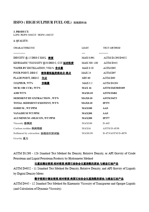
HSFO ( HIGH SULPHUR FUEL OIL) 高硫燃料油3. PRODUCT:LSFO /HSFO 380CST / HSFO 180CST4. QUALITY:CHARACTERISTIC LIMIT TEST METHOD-------------- ---- -----------DENSITY @ 15 DEG C KG/L 密度MAX 0.991 ASTM D1298/D4052 KINEMATIC VISCOSITY @50 DEG C, CST 运动粘度MAX 380 /180 ASTM D445WATER BY DISTILLATION, VOL% 含水量MAX 0.50 ASTM D95POUR POINT, DEG C 液体最低温度流动点-流点MAX 24 ASTM D97FLASH POINT, DEG C 闪点MIN 60 ASTM D93SULPHUR, WT% 含硫量MAX 3.5 ASTM D4294MCR( OR CCR), WT% MAX 16 ASTM D4530/D189ASH WT% MAX0.10 ASTM D482SEDIMENT BY EXTRACTION , WT% MAX0.10 ASTM D473TOTAL SEDIMENT EXISTENT, WT% MAX0.10 IP375SODIUM , WT PPM MAX100 AASV ANADIUM WT PPM MAX200 AASALUMINIUM +SILICON, WT PPM MAX200 IP377Viscosity黏稠度MAX540 D-445Carbon residue焦炭残渣MAX16 ASTM D-4530Sediment by extraction 抽提法沉淀试验MAX0.50 D-473/ASTM D-4870 Gravity重力ASTM D1298 - 12b Standard Test Method for Density, Relative Density, or API Gravity of Crude Petroleum and Liquid Petroleum Products by Hydrometer Method比重法测定密度,相对密度,美国石油协会比重指数的原油,与液态石油产品ASTM D4052 - 11 Standard Test Method for Density, Relative Density, and API Gravity of Liquids by Digital Density Meter数字密度计测定密度,相对密度,美国石油协会比重指数的原油,与液态石油产品ASTM D445 - 12 Standard Test Method for Kinematic Viscosity of Transparent and Opaque Liquids (and Calculation of Dynamic Viscosity)标准测试透明的与不透明的运动粘度, 与估算的运动粘度方法ASTM D95 - 05(2010) Standard Test Method for Water in Petroleum Products and Bituminous Materials by Distillation标准蒸馏法测定石油新产品与沥青材料的含水量ASTM D93 - 12 Standard Test Methods for Flash Point by Pensky-Martens Closed Cup Tester 标准Pensky-Martens闭杯闪点测定器测定闪点ASTM D97 - 12 Standard Test Method for Pour Point of Petroleum Products标准石油产品流点测试方法ASTM D4294 - 10 Standard Test Method for Sulfur in Petroleum and Petroleum Products by Energy Dispersive X-ray Fluorescence Spectrometry用能量色散X射线荧光光谱法测定石油及产品的硫含量。
ASTM D3574中文版

此项测试是事先将试样压缩到
规定的间距,进而将压制试样放 入特定氛围中保持一段时间后 将试样在特定环境中恢复形变, 测量试样前后的厚度变化
测试三个试样 最终数值应为三试样测试值的均值
Page 9
测试装置—— 压缩装置
该压缩装置由两块或者两块以上的平整面板并排组成, 板与板之间由螺栓固定而不至于产生相对滑动,平板之 间安放垫片保证相对的两块板是平行的状态。
对于片材,表面和底部都有镀膜或者保护层的样品表面应不低于 0.1㎡,在接近拉伸和撕裂取样的区域取出试样,此时试样的厚度为 片材的整体厚度;如果客户有特殊要求,则可按照实际情况进行操 作。
Page 5
测试方法
质量: 使用精确电子天平测量 试样质量,误差不超过1% 体积: 按照Section 8 试样测量
Thanks very much for your attention
3F
®
Performance Foam
Page 19
Page 15
试样制备
测试样品应从厚度为12.5±1.5mm的质地均一的片材 中取出,泡棉测试的上升方向应该为厚度方向,除非客 户有特殊要求;试样表面和底部应该平行且没有表面镀 层,切面与上下表面都应该相互垂直并无边缘毛边。
Page 16
测试流程
将上下夹具的距离设置为62.5mm(D 3574模具样品) 或者为75mm(D 412模具样品);将试样装入夹具中, 将上下的位置调整到平衡状态,以保证试样在做拉伸测 试时试样的每一部分都能承受均一的力量;客户如没有 特殊要求,拉伸测试的速度一般为500mm/min,持续 关注水准标准刻度的变化直至拉伸试验结束。如果仪器 本身没有自动记录功能就必须手动记录拉伸应力的变化。 待样品拉伸至断裂时,测试结束,记录并测量断裂时的 伸长量。
ASTM C297
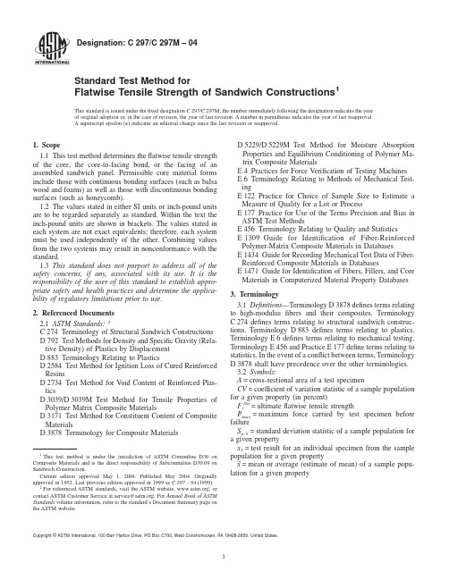
Designation:C297/C297M–04Standard Test Method forFlatwise Tensile Strength of Sandwich Constructions1This standard is issued under thefixed designation C297/C297M;the number immediately following the designation indicates the year of original adoption or,in the case of revision,the year of last revision.A number in parentheses indicates the year of last reapproval.A superscript epsilon(e)indicates an editorial change since the last revision or reapproval.1.Scope1.1This test method determines theflatwise tensile strength of the core,the core-to-facing bond,or the facing of an assembled sandwich panel.Permissible core material forms include those with continuous bonding surfaces(such as balsa wood and foams)as well as those with discontinuous bonding surfaces(such as honeycomb).1.2The values stated in either SI units or inch-pound units are to be regarded separately as standard.Within the text the inch-pound units are shown in brackets.The values stated in each system are not exact equivalents;therefore,each system must be used independently of the bining values from the two systems may result in nonconformance with the standard.1.3This standard does not purport to address all of the safety concerns,if any,associated with its use.It is the responsibility of the user of this standard to establish appro-priate safety and health practices and determine the applica-bility of regulatory limitations prior to use.2.Referenced Documents2.1ASTM Standards:2C274Terminology of Structural Sandwich Constructions D792Test Methods for Density and Specific Gravity(Rela-tive Density)of Plastics by DisplacementD883Terminology Relating to PlasticsD2584Test Method for Ignition Loss of Cured Reinforced ResinsD2734Test Method for V oid Content of Reinforced Plas-ticsD3039/D3039M Test Method for Tensile Properties of Polymer Matrix Composite MaterialsD3171Test Method for Constituent Content of Composite MaterialsD3878Terminology for Composite MaterialsD5229/D5229M Test Method for Moisture Absorption Properties and Equilibrium Conditioning of Polymer Ma-trix Composite MaterialsE4Practices for Force Verification of Testing Machines E6Terminology Relating to Methods of Mechanical Test-ingE122Practice for Choice of Sample Size to Estimate a Measure of Quality for a Lot or ProcessE177Practice for Use of the Terms Precision and Bias in ASTM Test MethodsE456Terminology Relating to Quality and StatisticsE1309Guide for Identification of Fiber-Reinforced Polymer-Matrix Composite Materials in DatabasesE1434Guide for Recording Mechanical Test Data of Fiber-Reinforced Composite Materials in DatabasesE1471Guide for Identification of Fibers,Fillers,and Core Materials in Computerized Material Property Databases 3.Terminology3.1Definitions—Terminology D3878defines terms relating to high-modulusfibers and their composites.Terminology C274defines terms relating to structural sandwich construc-tions.Terminology D883defines terms relating to plastics. Terminology E6defines terms relating to mechanical testing. Terminology E456and Practice E177define terms relating to statistics.In the event of a conflict between terms,Terminology D3878shall have precedence over the other terminologies.3.2Symbols:A=cross-sectional area of a test specimenCV=coefficient of variation statistic of a sample population for a given property(in percent)F z ftu=ultimateflatwise tensile strengthP max=maximum force carried by test specimen before failureS n-1=standard deviation statistic of a sample population for a given propertyx1=test result for an individual specimen from the sample population for a given propertyx¯=mean or average(estimate of mean)of a sample popu-lation for a given property1This test method is under the jurisdiction of ASTM Committee D30onComposite Materials and is the direct responsibility of Subcommittee D30.09onSandwich Construction.Current edition approved May1,2004.Published May2004.Originallyapproved st previous edition approved in1999as C297–94(1999).2For referenced ASTM standards,visit the ASTM website,,orcontact ASTM Customer Service at service@.For Annual Book of ASTMStandards volume information,refer to the standard’s Document Summary page onthe ASTM website.1Copyright©ASTM International,100Barr Harbor Drive,PO Box C700,West Conshohocken,PA19428-2959,United States.4.Summary of Test Method4.1This test method consists of subjecting a sandwich construction to a uniaxial tensile force normal to the plane of the sandwich.The force is transmitted to the sandwich through thick loading blocks,which are bonded to the sandwich facings or directly to the core.4.2The only acceptable failure modes forflatwise tensile strength are those which are internal to the sandwich construc-tion.Failure of the loading block-to-sandwich bond is not an acceptable failure mode.5.Significance and Use5.1In a sandwich panel,core-to-facing bond integrity is necessary to maintain facing stability and permit load transfer between the facings and core.This test method can be used to provide information on the strength and quality of core-to-facing bonds.It can also be used to produceflatwise tensile strength data for the core material.While it is primarily used as a quality control test for bonded sandwich panels,it can also be used to produceflatwise tensile strength data for structural design properties,material specifications,and research and development applications.5.2Factors that influence theflatwise tensile strength and shall therefore be reported include the following:facing material,core material,adhesive material,methods of material fabrication,facing stacking sequence and overall thickness, core geometry(cell size),core density,adhesive thickness, specimen geometry,specimen preparation,specimen condi-tioning,environment of testing,specimen alignment,loading procedure,speed of testing,facing void content,adhesive void content,and facing volume percent reinforcement.Properties that may be derived from this test method includeflatwise tensile strength.6.Interferences6.1Material and Specimen Preparation—Poor material fabrication practices,lack of control offiber alignment,and damage induced by improper specimen machining are known causes of high data scatter in composites in general.Specific material factors that affect sandwich composites include vari-ability in core density and degree of cure of resin in both facing matrix material and core bonding adhesive.Important aspects of sandwich panel specimen preparation that contribute to data scatter are incomplete or nonuniform core bonding to facings, misalignment of core and facing elements,the existence of joints,voids or other core and facing discontinuities,out-of-plane curvature,facing thickness variation,and surface rough-ness.6.2System Alignment—Excessive bending will cause pre-mature failure.Every effort should be made to eliminate excess bending from the test system.Bending may occur as a result of misaligned grips,poor specimen preparation,or poor align-ment of the bonding blocks and loadingfixture.If there is any doubt as to the alignment inherent in a given test machine,then the alignment should be checked as discussed in Test Method D3039/D3039M.6.3Geometry—Specific geometric factors that affect sand-wichflatwise tensile strength include core cell geometry,core thickness,specimen shape(square or circular),adhesive thick-ness,facing thickness,and facing per-ply thickness.6.4Environment—Results are affected by the environmen-tal conditions under which the tests are conducted.Specimens tested in various environments can exhibit significant differ-ences in both strength behavior and failure mode.Critical environments must be assessed independently for each facing, adhesive and core material tested.6.5Conditioning—As it is inappropriate to bond a moisture-conditioned specimen to the bonding blocks,it is necessary to perform the bonding operation prior to such conditioning.The presence of the bonding blocks will affect the degree of moisture intake into the specimen,in comparison to a non-bonded sample.7.Apparatus7.1Micrometers—The micrometer(s)shall use a4-to5-mm [0.16-to0.20-in.]nominal diameter ball-interface on irregular surfaces such as the bag-side of a facing laminate,and aflat anvil interface on machined edges or very smooth-tooled surfaces.The accuracy of the instrument(s)shall be suitable for reading to within1%of the sample length,width and thickness.For typical specimen geometries,an instrument with an accuracy of625mm[60.001in.]is desirable for thickness, length and width measurement.7.2Loading Fixtures—The loadingfixtures shall be self-aligning and shall not apply eccentric loads.A satisfactory type of apparatus is shown in Fig.1.The loading blocks shallbe FIG.1Flatwise Tension TestSetupsufficiently stiff to keep the bonded core or facings essentially flat under load.Loading blocks40to50mm[1.5to2.0in.] thick have been found to perform satisfactorily.Permissible tolerances for the loading blocks(along with alignment re-quirements)are provided in Fig.2.7.3Testing Machine—The testing machine shall be in accordance with Practices E4and shall satisfy the following requirements:7.3.1Testing Machine Configuration—The testing machine shall have both an essentially stationary head and a movable head.7.3.2Drive Mechanism—The testing machine drive mecha-nism shall be capable of imparting to the movable head a controlled velocity with respect to the stationary head.The velocity of the movable head shall be capable of being regulated in accordance with11.6.7.3.3Load Indicator—The testing machine load-sensing device shall be capable of indicating the total force being carried by the test specimen.This device shall be essentially free from inertia lag at the specified rate of testing and shall indicate the force with an accuracy over the force range(s)of interest of within61%of the indicated value.7.4Conditioning Chamber—When conditioning materials at non-laboratory environments,a temperature/vapor-level controlled environmental conditioning chamber is required that shall be capable of maintaining the required temperature to within63°C[65°F]and the required relative humidity level to within63%.Chamber conditions shall be monitored either on an automated continuous basis or on a manual basis at regular intervals.7.5Environmental Test Chamber—An environmental test chamber is required for test environments other than ambient testing laboratory conditions.This chamber shall be capable of maintaining the gage section of the test specimen at the required test environment during the mechanical test.8.Sampling and Test Specimens8.1Sampling—Test at leastfive specimens per test condi-tion unless valid results can be gained through the use of fewer specimens,as in the case of a designed experiment.For statistically significant data,consult the procedures outlined in Practice E122.Report the method of sampling.8.2Geometry—Test specimens shall have a square or cir-cular cross-section,and shall be equal in thickness to the sandwich panel thickness.Minimum specimen facing areas for various types of core materials are as follows:8.2.1Continuous Bonding Surfaces(for example,balsa wood,foams)—The minimum facing area of the specimen shall be625mm2[1.0in.2].8.2.2Discontinuous Cellular Bonding Surfaces(for ex-ample,honeycomb)—The required facing area of the specimen is dependent upon the cell size,to ensure a minimum number of cells are tested.Minimum facing areas are recommended in Table1for the more common cell sizes.These are intendedto FIG.2Permissible Bonded AssemblyTolerancesprovide approximately 60cells minimum in the test specimen.The largest facing area listed in the table (5625mm 2[9.0in.2])is a practical maximum for this test method.Cores with cell sizes larger than 9mm [0.375in.]may require a smaller number of cells to be tested in the specimen.8.3Specimen Preparation and Machining —Specimen preparation is extremely important for this test method.Take precautions when cutting specimens from large panels to avoid notches,undercuts,rough or uneven surfaces,or delaminations due to inappropriate machining methods.Obtain final dimen-sions by water-lubricated precision sawing,milling,or grind-ing.The use of diamond tooling has been found to be extremely effective for many material systems.Edges should be flat and parallel within the specified tolerances.Record and report the specimen cutting preparation method.8.4Labeling —Label the test specimens so that they will be distinct from each other and traceable back to the panel of origin,and will neither influence the test nor be affected by it.8.5Loading Fixture Bonding —The loading blocks shall be bonded to the core or facings of the test specimen using a suitable adhesive.To minimize thermal exposure effects upon the existing core-to-facing bonds,it is recommended that the assembly bonding temperature be at room temperature,or at least 28°C [50°F]lower than that at which the sandwich was originally bonded.Similarly,the assembly bonding pressure shall not be greater than the original facing-to-core bonding pressure.Permissible tolerances for the bonded assembly (along with alignment requirements)are provided in Fig.2.9.Calibration9.1The accuracy of all measuring equipment shall have certified calibrations that are current at the time of use of the equipment.10.Conditioning10.1Standard Conditioning Procedure —Unless a different environment is specified as part of the experiment,condition the test specimens in accordance with Procedure C of Test Method D 5229/D 5229M,and store and test at standard laboratory atmosphere (2363°C [7365°F]and 5065%relative humidity).11.Procedure11.1Parameters to Be Specified Before Test :11.1.1The specimen sampling method,specimen geometry,and conditioning travelers (if required).11.1.2The properties and data reporting format desired.N OTE 1—Determine specific material property,accuracy,and data reporting requirements prior to test for proper selection of instrumentation and data recording equipment.Estimate the specimen strength to aid intransducer selection,calibration of equipment,and determination of equipment settings.11.1.3The environmental conditioning test parameters.11.1.4If performed,sampling method,specimen geometry,and test parameters used to determine facing density and reinforcement volume.11.2General Instructions :11.2.1Report any deviations from this test method,whether intentional or inadvertent.11.2.2If specific gravity,density,facing reinforcement vol-ume,or facing void volume are to be reported,then obtain these samples from the same panels being tested.Specific gravity and density may be evaluated in accordance with Test Methods D 792.V olume percent of composite facing constitu-ents may be evaluated by one of the matrix digestion proce-dures of Test Method D 3171,or,for certain reinforcement materials such as glass and ceramics,by the matrix burn-off technique in accordance with Test Method D 2584.The void content equations of Test Method D 2734are applicable to both Test Method D 2584and the matrix digestion procedures.11.2.3Following final specimen machining,but before conditioning and testing,measure the specimen length and width or diameter.The accuracy of these measurements shall be within 0.5%of the dimension.Measure the specimen thickness;the accuracy of this measurement shall be within 625mm [60.001in.].Record the dimensions to three signifi-cant figures in units of millimetres [inches].11.3Bond the specimen to the bonding blocks,in accor-dance with the requirements of 8.5.11.4Condition the bonded specimens as required.Store the specimens in the conditioned environment until test time,if the test environment is different than the conditioning environ-ment.11.5Following final specimen conditioning,but before testing,re-measure the specimen length and width or diameter as in 11.2.3.11.6Speed of Testing —Set the speed of testing so as to produce failure within 3to 6min.If the ultimate strength of the material cannot be reasonably estimated,initial trials should be conducted using standard speeds until the ultimate strength of the material and the compliance of the system are known,and speed of testing can be adjusted.The suggested standard head displacement rate is 0.50mm/min [0.020in./min].11.7Test Environment —If possible,test the specimen under the same fluid exposure level used for conditioning.However,cases such as elevated temperature testing of a moist specimen place unrealistic requirements on the capabilities of common testing machine environmental chambers.In such cases,the mechanical test environment may need to be modified,for example,by testing at elevated temperature with no fluid exposure control,but with a specified limit on time to failure from withdrawal from the conditioning chamber.Record any modifications to the test environment.11.8Specimen Installation —Install the specimen/bonding block assembly into the test machine test fixture.11.9Loading —Apply a tensile force to the specimen at the specified rate while recording data.Load the specimen until rupture.TABLE 1Recommended Minimum Specimen Facing AreaMinimum Cell Size(mm [in.])Maximum Cell Size(mm [in.])Minimum Facing Area(mm 2[in.2])- 3.0[0.125]625[1.0]3.0[0.125] 6.0[0.250]2500[4.0]6.0[0.250]9.0[0.375]5625[9.0]11.10Data Recording —Record force versus head displace-ment continuously,or at frequent regular intervals.Record the maximum force,the failure force,and the head displacement at,or as near as possible to,the moment of rupture.11.11Failure Modes —Adhesive failures that occur at the bond to the loading blocks are not acceptable failure modes and the data shall be noted as invalid.The following failure modes are considered to be acceptable:11.11.1Core Failure —Tensile failure of the sandwich core.Pieces of the core may remain in the adhesive that bonds the core to the block or facing.11.11.2Cohesive Failure of Core-Facing Adhesive —Failure in the adhesive layer used to bond the facing to the core,with adhesive generally remaining on both the facing and core surfaces.11.11.3Adhesive Failure of Core-Facing Adhesive —Failure in the adhesive layer used to bond the facing to the core,with adhesive generally remaining on either the facing or the core surface,but not both.11.11.4Facing Tensile Failure —Tensile failure of the fac-ing,usually by delamination of the composite plies in the case of a fiber-reinforced composite facing.12.Validation12.1Values for ultimate properties shall not be calculated for any specimen that breaks at some obvious flaw,unless such flaw constitutes a variable being studied.Retests shall be performed for any specimen on which values are not calcu-lated.12.2A significant fraction of failures in a sample population occurring at the bond(s)to the loading blocks shall be cause to reexamine the means of force introduction into the material.Factors considered should include the fixture alignment,adhe-sive material,specimen surface characteristics,and uneven machining of specimen ends.13.Calculation13.1Ultimate Strength —Calculate the ultimate flatwise ten-sile strength using Eq 1and report the results to three significant figures.F z ftu 5P max /A(1)where:F z ftu =ultimate flatwise tensile strength,MPa [psi],P max =ultimate force prior to failure,N [lbf],and A =cross-sectional area,mm 2[in.2].13.2Statistics —For each series of tests calculate the aver-age value,standard deviation,and coefficient of variation (in percent)for ultimate flatwise tensile strength:x ¯5~(i 51n x 1!(2)S n 215Œ~(i 51nx 122n x¯2!/~n 21!(3)CV 51003S n 21/x ¯(4)where:x ¯=sample mean (average),S n-1=sample standard deviation,CV=sample coefficient of variation,%,n =number of specimens,and x 1=measured or derived property.14.Report14.1Report the following information,or references point-ing to other documentation containing this information,to the maximum extent applicable (reporting of items beyond the control of a given testing laboratory,such as might occur with material details or panel fabrication parameters,shall be the responsibility of the requestor):N OTE 2—Guides E 1309,E 1434and E 1471contain data reporting recommendations for composite materials and composite materials me-chanical testing.14.1.1The revision level or date of issue of this test method.14.1.2The name(s)of the test operator(s).14.1.3Any variations to this test method,anomalies noticed during testing,or equipment problems occurring during testing.14.1.4Identification of all the materials consistuent to the sandwich panel specimen tested,including for each:material specification,material type,manufacturer’s material designa-tion,manufacturer’s batch or lot number,source (if not from manufacturer),date of certification,expiration of certification,facing filament diameter,tow or yarn filament count and twist,sizing,form or weave,fiber areal weight,matrix type,facing matrix content and volatiles content,ply orientation and stacking sequence of the facings.14.1.5Description of the fabrication steps used to prepare the sandwich panel including:fabrication start date,fabrication end date,process specification,cure cycle,consolidation method,and a description of the equipment used.14.1.6Ply orientation and stacking sequence of the facing laminate.14.1.7If requested,report facing density,volume percent reinforcement,and void content test methods,specimen sam-pling method and geometries,test parameters and test results.14.1.8Results of any nondestructive evaluation tests.14.1.9Method of preparing the test specimen,including specimen labeling scheme and method,specimen geometry,sampling method,and specimen cutting method.14.1.10Calibration dates and methods for all measurements and test equipment.14.1.11Details of loading blocks and apparatus,including dimensions and material used.14.1.12Type of test machine,alignment results,and data acquisition sampling rate and equipment type.14.1.13Measured length and width (or diameter)and thick-ness for each specimen (prior to and after conditioning,if appropriate).14.1.14Weight of specimen.14.1.15Method of bonding specimens to blocks;adhesive,cure cycle,and pressure.14.1.16Conditioning parameters and results.14.1.17Relative humidity and temperature of the testing laboratory.14.1.18Environment of the test machine environmental chamber (if used)and soak time at environment.14.1.19Number of specimenstested.14.1.20Speed of testing.14.1.21Individual ultimateflatwise tensile strengths and average value,standard deviation,and coefficient of variation (in percent)for the population.14.1.22Force versus crosshead displacement data for each specimen so evaluated.14.1.23Failure mode,location of failure,percentage of failure area of core,adhesive(cohesive or adhesive failure),or facing for each specimen.15.Precision and Bias15.1Precision—The data required for the development of a precision statement is not available for this method.15.2Bias—Bias cannot be determined for this method as no acceptable reference standards exist.16.Keywords16.1core;facing;flatwise tension;sandwich;sandwich construction;tensile strengthASTM International takes no position respecting the validity of any patent rights asserted in connection with any item mentioned in this ers of this standard are expressly advised that determination of the validity of any such patent rights,and the risk of infringement of such rights,are entirely their own responsibility.This standard is subject to revision at any time by the responsible technical committee and must be reviewed everyfive years and if not revised,either reapproved or withdrawn.Your comments are invited either for revision of this standard or for additional standards and should be addressed to ASTM International Headquarters.Your comments will receive careful consideration at a meeting of the responsible technical committee,which you may attend.If you feel that your comments have not received a fair hearing you should make your views known to the ASTM Committee on Standards,at the address shown below.This standard is copyrighted by ASTM International,100Barr Harbor Drive,PO Box C700,West Conshohocken,PA19428-2959, United States.Individual reprints(single or multiple copies)of this standard may be obtained by contacting ASTM at the above address or at610-832-9585(phone),610-832-9555(fax),or service@(e-mail);or through the ASTM website().。
混凝土吸水性标准
混凝土吸水性标准一、引言混凝土作为建筑物的重要结构材料,其水分吸收性能对于建筑物的使用寿命和安全性具有重要影响。
因此,确定混凝土吸水性标准十分必要。
二、混凝土吸水性的定义混凝土吸水性指混凝土的水分吸收能力,即在一定时间内,混凝土中所吸收的水量与其单位面积的吸收面积之比。
三、混凝土吸水性的影响因素1. 水泥品种和用量:水泥的种类和用量直接影响混凝土的密实性和强度,从而影响混凝土的吸水性能。
2. 级配和骨料种类:骨料种类和级配对混凝土的孔隙结构有直接影响,从而影响混凝土的吸水性能。
3. 混凝土配合比:混凝土配合比的不同会直接影响混凝土的密实性和孔隙结构,从而影响混凝土的吸水性能。
4. 养护条件:混凝土的养护条件直接影响混凝土的强度和孔隙结构,从而影响混凝土的吸水性能。
四、混凝土吸水性标准的分类根据混凝土吸水性的不同,其标准也会有所不同。
目前,常见的混凝土吸水性标准主要有以下几种:1. GB/T 50082-2009《混凝土结构工程施工质量验收规范》2. GB/T 11968-2006《混凝土抗渗性能试验方法标准》3. JGJ/T 70-2009《建筑工程混凝土质量检验标准》4. ASTM C642-13《Standard Test Method for Density, Absorption, and Voids in Hardened Concrete》五、混凝土吸水性标准的具体要求1. GB/T 50082-2009《混凝土结构工程施工质量验收规范》该标准规定了混凝土吸水性的限制值,要求混凝土在28天龄期内吸水率应不超过8%。
2. GB/T 11968-2006《混凝土抗渗性能试验方法标准》该标准规定了混凝土抗渗性能的试验方法,其中包括了混凝土吸水性的测试方法。
该标准要求混凝土样品在试验前应充分养护,测试时应按照规定的方法进行,测试结果应符合规定的要求。
3. JGJ/T 70-2009《建筑工程混凝土质量检验标准》该标准规定了混凝土吸水性的检验方法,要求混凝土的吸水性应按照规定的方法进行测试,并要求测试结果应符合规定的要求。
美国石油工程师协会API标准更新通知(2023-01)
API MPMS Chapter 9.2, Standard Test Method for Density or Relative Density of Light Hydrocarbons by Pressure Hydrometer, 4th Edition has been published in November 2022. This test method covers the determination of the density or relative density of light hydrocarbons including liquefied petroleum gases (LPG) having Reid vapor pressures exceeding 101.325 kPa (14.696 psi).API RP 13J, Testing of Heavy Brines, 6th Edition has been published in January 2023.This standard covers the physical properties, potential contaminants, and test procedures for heavy brine fluids manufactured for use in oil and gas well drilling, completion, fracturing, and workover fluids.This standard provides methods for assessing the performance and physical characteristics of heavy brines for use in field operations. It includes procedures for evaluating the density or specific gravity, the clarity or amount of particulate matter carried in the brines, the crystallization point or the temperature at which the brines make the transition between liquid and solid at atmospheric pressure (a discussion of crystallization temperature under pressure is provided in Annex C), the pH, iron contamination, and buffering capacity.API MPMS Chapter 17.2, Measurement of Cargoes on Board Tank Vessels, 3rd Edition has been published in January 2023.The determination of the quantity and quality of cargo on board marine tank vessels is frequently complex. It is necessary to accurately gauge, ascertain the temperature of, collect samples of, and calculate the amount of all materials contained in the vessel’s lines, cargo tanks, and slop tanks. Other spaces on the vessel may also contain cargo, such as ballast tanks, double bottoms, cofferdams, and numerous other non-designated cargo spaces, all of which have to be checked, and any volumes contained in them calculated. Measurement accountability (quantity and quality) has to further take into account conditions such as, but not limited to, OBQ/ROB, line fullness, preloading tank inspection, closed measurement and sampling systems, and special procedures for chemical and gas cargoes. Reconciliation of the foregoing may be required if gains or losses exceed expected tolerances.The detailed requirements for performing all of these actions are contained in numerous MPMS standards. This publication identifies the methods for performing these procedures on crude oils; petroleum products; chemical cargoes; LPG and LNG, normally carried on board marine tank vessels; and guides the user to the appropriate standard/guidance document within the MPMS suite of standards.API MPMS Chapter 22.7, Testing Protocol for Multiphase Meter, 1st Edition has been published in January 2023.This testing protocol provides the minimum requirements for documenting performance testing of an inline multiphase flow meter under controlled flowing conditions in a flow loop facility. Completion of the testing protocol is not a calibration and does not replace field testing and validation.This testing protocol documents the method for testing the performance characteristics of multiphase flow meters used in production allocation. The testing protocol includes a listing of parameters affecting the performance of the devices, a description of the tests required, requirements for the test facility, a data reporting format, and an uncertainty determination methodology.。
砂的检测项目及标准
砂的检测项目及标准砂的检测项目和标准可能因不同行业和应用而有所差异。
以下是一些常见的砂的检测项目和标准:1. 粒度分析:评估砂的颗粒大小分布。
标准可以是ASTMC136-06中的"Standard Test Method for Sieve Analysis of Fine and Coarse Aggregates"。
2. 湿度测试:评估砂的含水量。
标准可以是ASTM C566-97中的"Standard Test Method for Total Evaporable Moisture Contentof Aggregate by Drying"。
3. 含泥量测试:评估砂中的泥和粘土含量。
标准可以是ASTM C117-17中的"Standard Test Method for Materials Finer than 75-μm (No. 200) Sieve in Mineral Aggregates by Washing"。
4. 重量密度测试:评估砂的重量和体积之比。
标准可以是ASTM C127-15中的"Standard Test Method for Density, Relative Density (Specific Gravity), and Absorption of Coarse Aggregate"。
5. 其他物理性质测试:包括砂的孔隙度、堆积密度、沉降性等。
标准可以根据具体应用和需求而有所不同。
请注意,以上仅为一些常见的砂的检测项目和对应标准的举例,实际应用中可能还有其他项目和标准。
具体的检测项目和标准应根据具体行业和应用来确定。
建议参考相关行业的标准组织、政府规定或行业标准,如ASTM、ISO等。
法国NF阻燃、防火测试标准(中英文)
法国NF阻燃、防火测试标准NF C20-453:基本环境测试程序.测试方法.烟雾腐蚀性的常规测试NF C20-453:Basic environmental testing procedures. Test methods. Conventional determination of corrosiveness of smoke.NF C20-454:基本环境测试程序.测试方法.火灾特性.气体在高温分解过程中的分析和滴定或电工用材料的燃烧.异常热力或火灾辐照.管式炉法NF C20-454:Basic environmental testing procedures. Test methods. Fire behaviour.Analysis and titrations of gases evolved during pyrolysis or combustion ofmaterials used in electrotechnics. Exposure to abnormal heat or fire. Tubefurnace method.NF C32-070:设备用绝缘电缆和柔性软线.按绝缘电缆和软线耐火性进行分类测试NF C32-070:Insulated cables and flexible cords for installations - Classification tests on cables and cords with respect to their behaviour to fireHalogen Free Control Cable With Numbered Conductors, NF C32-070 C1 is a halogen free multi-conductor, flexible power and control cable designed for use in all electrical equipment in dry, damp and wet conditions. Recommended applications include machinery, data processing equipment, ventilation and air conditioning systems. In case of fire, no corrosive gases are produced. This cable is particularly suitable for use where human life and valuable property are exposed to an extremely high risk of fire.NF C32-073:燃烧时电缆的通用测试方法.在规定条件下电缆燃烧时烟密度的测量NF C32-073:Common test methods for cables under fire conditions - Measurement of smoke density of cables burning under defined conditionsNF C32-074:火灾情况下电缆的一般测试方法-电缆材料燃烧时产生的气体的测试NF C32-074:Common test methods for cables under fire conditions - Test on gases evolved during combustion of materials from cablesNF C32-310:设备用绝缘电缆和软线-额定电压高达0.6/1 kV 的耐火(CR1级)电缆和软线NF C32-310:Insulated cables and flexible cords for installation-Fire resistant (class CR1) cables and flexible cords for rated voltage up to and including 0,6/1 kv.NF F16-101:铁路车辆.防火性能.材料的选择NF F16-101:Rolling stock,Fire behaviour. Materials choosingNF F16-101/NF F16-102法国轨道车辆阻燃防火测试标准根据标准化试验的结果,提出轨道车辆材料分类的方法。
- 1、下载文档前请自行甄别文档内容的完整性,平台不提供额外的编辑、内容补充、找答案等附加服务。
- 2、"仅部分预览"的文档,不可在线预览部分如存在完整性等问题,可反馈申请退款(可完整预览的文档不适用该条件!)。
- 3、如文档侵犯您的权益,请联系客服反馈,我们会尽快为您处理(人工客服工作时间:9:00-18:30)。
QC/001
Standard operation
Reviewed by Quality Manager
Approved by Quality Manager
Foam Specific Density Test
Method
Issued date 10/31/08
Version 00
1. Sampling:
1) EPE Foam (roll):
For each lot, choose 3 set of 5 samples, each set from a different roll, dimension:
100*100mm±10mm. Then number those samples.
2. Test method:
2.1 Weight: Use a scale to weigh each piece of sample, accurate to 0.1g, then record as P1, P2, P3.
2.2 Volume: Use volume displacement method to get the volume of each sample.
1) Test equipment: a. 1 graduated cylinder of 1000ml (accurate to 10ml); b. a metal frame.
2) Put the metal frame into the cylinder, pour some fresh water into the cylinder, stop when the
water level is enough. Record this water level as V
3) And then put the sample with the frame into the water;
4) When the water stops moving inside the cylinder, observe the reading of the water level in the
cylinder, record as Vt1
5) Lift the metal frame vertically out of the water, take out the sample. Then put the metal frame
into the cylinder and add more water into the cylinder until the water level is the same as V, and
repeat the same as 2), 3), 4) above.
6) The result of Vt1,Vt2 & Vt3 minus V getting the volume of sample as V1, V2 & V3
2.3 Calculate the density of the sample Di (g/c㎡):
Đo mật độ của mẫu là Di(g/c cm2)
Di = Pi/ Vi
The density of each sample shall be recorded as Di (D1, D2, D3), then calculate the average density
D(g/c㎡) : D = (D1+D2+D3) / 3
1。采样:
1)EPE片材:
对于每一个批次,选择5个样品3套,每一套不同的片材尺寸:100* 100MM±10毫米。然
后这些样品如下方法进行测试
.
2。测试方法:
2.1重量:用一个尺度去衡量每一块样品,精确至0.1g,然后记录为P1,P2,P3的。
2.2体积:使用位移量的方法来获得每个样品量。
1)测试设备:A. 1千毫升量筒(精确到10ml);B ,金属框架。
QC/001
Standard operation
Reviewed by Quality Manager
Approved by Quality Manager
Foam Specific Density Test
Method
Issued date 10/31/08
Version 00
2
)放入缸中的金属框架,倒入一些新鲜的水进入气缸,停止时的水位是足够的。记录此水
位为
V
3),然后把样品入水框架;
4)当水停止气缸内的移动,在汽缸内观察,记录水位读数为VT1
5
)电梯垂直出水中的金属框架,取出样品。然后把进入气缸的金属框架,并添加更多的水
进入气缸,直到水位为V相同,并重复相同为2),3),4)以上。
6)VT1,VT2和VT3减去V,V1,V2和V3的样本量
2.3计算样品的密度DI(G/ C㎡):
DJO垫ĐộCUA茂拉迪(G / C平方厘米)
DI = PI / VI
应迪(D1,D2,D3)记录每个样品的密度,然后计算平均密度D(G / C㎡):D=(
D1+ D2
+ D3)/3