DC-9503E隔离器安装手册
离网逆变器安装手册

离网逆变器使用手册编制:李凡审核:批准:成都旭双太阳能科技有限公司光伏项目部二O一一年五月请在安装逆变器之前仔细阅读本手册。
本手册介绍了离网逆变器的使用注意事项、安装要求及安装方法,系统加电及调试过程,系统使用及操作方法,系统维护及应急处理等基本知识。
本手册可以帮助您正确使用和维护逆变设备。
本手册适用于对逆变器安装、操作、维护专业技术人员及日常操作的用户。
读者需具备一定的电气知识,熟悉电气原理图和电子元器件特性。
本手册内容都为成都旭双太阳能科技有限公司所有,非公司内部人员未经书面授权不得公开转载全部或部分内容。
编者2011年5月18日目录一、安全说明 (1)1.1安装前 (1)1.2安装中 (1)1.3维修 (2)1.4其他 (2)二、逆变器安装 (4)2.1安装流程 (4)2.1.1 安装前准备 (4)2.1.2 场地选择 (5)2.1.3 机械安装 (6)2.1.4 电气连接 (6)2.1.5通讯线连接: (8)2.2试运行 (9)2.1.2 试运行前检查: (9)2.1.3 试运行: (10)三、逆变器维护 (11)四、结语 (12)一、安全说明逆变器是作为电力电子产品,在安装、操作和维护过程中需要严格遵循相关安全注意事项。
不正确使用或误操作将可能危害:●操作者和第三方的生命和人身安全。
●逆变器和属于操作者或第三方的其他财产。
1.1安装前✧当收到产品时应首先检查逆变器是否在运输过程中有无损坏。
若发现问题请立即与生产厂家或运输公司联系。
✧在选择安装场地时,应保证周围内没有任何其他电力电子设备的干扰。
1.2安装中✧在进行电气连接之前,务必采用不透光材料将光伏电池板覆盖或断开直流侧断路器。
暴漏于阳光,光伏阵列将会产生危险电压。
✧所有安装操作必须且仅有安装技术人员完成。
✧光伏系统中所使用的电缆必须连接牢固,良好绝缘以及规格合适。
✧所有的电气安装必须满足当地以及国家电气标准。
1.3维修✧在进行任何维修工作之前,应首先断开逆变器和负载的连接,然后断开直流侧电气连接。
Eaton OEM线路隔离器(OLI)安装验证说明书

ContentsDescription Page How to defeat the two door interlocks prior to operating the OLI handle . . . . . . . . . . . . . . . . . . . .2OLI switch mechanism inspection . . . . . . . . . . . .5Switching base inspection . . . . . . . . . . . . . . . . . . .6Control cabinet handle mechanisminspection . . . . . . . . . . . . . . . . . . . . . . . . . . . . . . .7Reference drawings . . . . . . . . . . . . . . . . . . . . . . .11installation verification instructions2Instruction Leaflet IB008001ENEffective September 2019Eaton OEM line isolation (OLI) installation verification instructionsEATON This document outlines the parts that can be inspected to verify proper installation and adjustment of the handle / operating mecha-nism inside Eaton OLI switches in accordance with the instruction leaflet (IL008019EN) . The instruction leaflet includes the official installation instructions for the Eaton OLI switch . .Prior to opening the OLI cabinet or control cabinet verify that no live voltage is present.m WARNINGDO NOT ATTEMPT TO INSTALL OR PERFORM MAINTENANCE ONEQUIPMENT WHILE IT IS ENERGIZED. SEVERE PERSONAL INJURY, DEATH, OR SUBSTANTIAL PROPERTY DAMAGE CAN RESULT FROM CONTACT WITH ENERGIZED EQUIPMENT. ALWAYS VERIFY THAT NO VOLTAGE IS PRESENT BEFORE PROCEEDING WITH THE TASK, AND ALWAYS FOLLOW GENERALLY ACCEPTED SAFETY PROCEDURES.EATON IS NOT LIABLE FOR THE MISAPPLICATION OR MISINSTALLATION OF ITS PRODUCTS.If operating the OLI handle mechanism with one or both doors open, ensure that the corresponding interlock is defeated to avoid damage.m WARNINGWHEN INSTALLING A NEW HANDLE MECHANISM, OR NEW DISCON-NECT AND HANDLE MECHANISM IN AN EXISTING ELECTRICAL SYSTEM, MAKE SURE THERE IS NO VOLTAGE PRESENT WHERE WORK IS TO BE PERFORMED. SPECIAL ATTENTION SHOULD BE PAID TO REVERSE FEED APPLICATIONS TO ENSURE NO VOLTAGE IS PRESENT. THE VOLTAGE IN ENERGIZED EQUIPMENT CAN CAUSE DEATH OR SEVERE PERSONAL INJURY.The user is cautioned to observe all recommendations, warnings, and cautions relating to the safety of personnel and equipment as well as all general local health and safety laws, codes, and proce-dures .The recommendations and information contained herein are based on Eaton’s experience and judgment, but should not be considered to be all-inclusive or covering every application or circumstance which may arise . If any questions arise, contact Eaton for further information or instructions .How to defeat the two door interlocks prior to operating the OLI handleFigure 1. Door interlock mechanism inside control cabinet.3Instruction Leaflet IB008001ENEffective September 2019Eaton OEM line isolation (OLI)installation verification instructions EATON Press down on the door hasp on the handle mechanism inside the control cabinet as pictured (see Figure 2) .Figure 2. Defeat control cabinet door interlock.Press up on mechanism defeat lever on right side of OLI switch at the same time as the door hasp prior to moving the operating handle to the “ON” position with the control cabinet and OLI door open (see Figure 3) .Figure 3. Defeat OLI door interlock.4Instruction Leaflet IB008001ENEffective September 2019Eaton OEM line isolation (OLI) installation verification instructionsEATON Identify catalog number and date codeThe catalog number is located at the top left of the publication inside the OLI cabinet . The switch’s date code is located part way down on the left-hand side .Figure 4. Location of the catalog number and date code.Flex cable lengthFind the flex cable length printed along the black flexible shaft cable that connects the handle mechanism to the OLI operating mecha-nism . Standard cable length is 60 in .(1,524 mm) for 30 A – 200 A OLI and 72 in . (1,829 mm) for 400 A – 600 A OLI (see Figure 5) .Figure 5. Location of the flex cable length.Measurement from front of control cabinetMeasure the distance between the front of the OLI door and the front of the control cabinet door . In Figure 6, the measurement is 0 as the OLI cabinet is installed flush with the front of the control cabi-net enclosure . The design tolerance is to mount the front of the OLI within 6 in . (152 .4 mm) of the front of the control cabinet .Figure 6. OLI cabinet is installed flush with the front of thecontrol cabinet enclosure.Control cabinet door5Instruction Leaflet IB008001ENEffective September 2019Eaton OEM line isolation (OLI)installation verification instructions EATON OLI switch mechanism inspectionThis section verifies the installation and adjustment of the flex shaft handle to the switching mechanism located near the right side-walll of the OLI enclosure .Confirm door interlock functionalityWith the OLI door closed and the operating handle in the ON posi-tion loosen the enclosure door hold down screws on the right-hand side of the enclosure . With all screws loose confirm that the mecha-nism interlock prevents the OLI door from opening while the handle remains in the ON position . If the OLI door opens with the handle in the ON position the door interlock is not operating properly . This could be the result of improper adjustment of the cylinder connector . To evaluate the connection of the flexible shaft operation cable to the cylinder connector turn the operating handle to the OFF position and open the OLI door .Figure 7. Location of cylinder connector threads and E-ring.Number of threads showing on cylinder connectorThe cylinder connector is what threads on to the flexible shaftoperating cable and connects to the OLI switch mechanism . Verify there are at least four threads showing above the cylinder connector .Ensure that the E-ring is installed on the operating mechanism .0 threads showing E-ring5 threads showingCylinder connector6Instruction Leaflet IB008001ENEffective September 2019Eaton OEM line isolation (OLI) installation verification instructionsEATON Bulk head nut adjustment and tightnessConfirm that the bulk head nuts are tight on either side of the mech-anism bracket and that they are near the bottom of the thread end .Figure 8. Correct placement of the bulk head nuts.Switching base inspectionThis section is for inspection of the switching base to ensure that it is operating properly and that the electrical connections inside are tight .With the control cabinet door closed and the OLI mechanism defeat lever depressed ensure that the switch blades open and close fully when the operating handle is turned OFF and ON .Figure 9. Switch base and fuses.Figure 10. Lexan line shield and switch base.Bulk head nutsbladesOLI mechanism7Instruction Leaflet IB008001ENEffective September 2019Eaton OEM line isolation (OLI)installation verification instructions EATON Line shieldVerify that the clear Lexan line shield is installed inside the OLI . It may need to be removed for the inspection of the other switch base components but should be re-installed after the inspection .Switching base lugsVerify that the switch base lugs (line and load) are securely attached to the switch base . Verify that the line and load conductors are tight in the mechanical lugs . If voltage indicators are installed, ensure that the ring terminals are securely fastened under the lug terminal hold down screws and are tight in the terminal blocks where line and or load side voltage indicators are connected . Reference torque value chart on publication inside of OLI door . Also confirm that fuses are properly installed in the fuse clips .Figure 11. Switch base components.Control cabinet handle mechanism inspectionFor this portion of the inspection the handle mechanism inside the control cabinet will be inspected for proper adjustment and condi-tion .Control cabinet door interlockTo test the control cabinet door interlock close both the OLI and control cabinet doors . With the operating handle in the ON position ensure that the control cabinet door will not open . This ensures that the door hasp on the handle mechanism is operating properly and catches the door hardware on the control cabinet . Some control cabinets are not readily compatible with the Eaton C371 handle operator and require modification to properly interlock .Figure 12. Hardware included with OLI to extend or replace existing control cabinet door hardware, if required 1.Figure 13. Control cabinet door hardware and door hasp on handle mechanism.1 Eaton Catalog # OLIHOFFKIT1 available to modify someHoffman Enclosure doorsModified control cabinet door hardwareDoor hasp onhandle mechanismTerminal blocksVoltage indicator wire ring terminals Line side lugs (unwired)8Instruction Leaflet IB008001ENEffective September 2019Eaton OEM line isolation (OLI) installation verification instructionsEATON Pivot bracket inspectionConfirm that the handle mechanism hardware is tight on the operat-ing handle .Figure 14. Handle mechanism and mounting hardware.From inside the control cabinet (back of the handle mechanism) confirm that there are threads showing above and below the pivot bracket attachment for the flexible shaft handleFigure 15. Threads showing above and below the pivot bracketattachment for the flexible shaft handle.Handle mechanism hardwareThreads9Instruction Leaflet IB008001ENEffective September 2019Eaton OEM line isolation (OLI)installation verification instructions EATON Actuator link and adapter link rivet and hardwareEnsure that the rivet connecting the actuator link and adapter link extends through the front and back of both links .Figure 16. Adapter link hardware.Rivet through front of adapter link Bolt through front ofadapter linkThe screw attaching the actuator link and adapter link in the handle mechanism should be tight with threads showing from the washer and nut on the back side of the actuator link .Figure 17. Actuator link hardware.Washer, nut, and bolt threads through back of actuator linkRivet through back of actuator link10Instruction Leaflet IB008001ENEffective September 2019Eaton OEM line isolation (OLI) installation verification instructionsEATON E-ring and actuator link springEnsure that pivot bracket E-ring is installed, actuator link spring isinstalled, and door hasp screws are tight .Figure 18. Control cabinet handle mechanism.Flex shaft cable routingPrior to closing the control cabinet door, confirm that the flex shaft cable is routed to minimize any sharp bends . The photo depicts a standard 60A OLI with a 60 in . (1,524 mm) flex shaft cable which should have some slack inside the control cabinet .Figure 19. Flex shaft cable routing.E-ringDoor hasp screwsActuator link springFlex shaft cable routingFinal operational checkWith the OLI cabinet screwed closed and the control cabinet door closed verify the proper operation of the handle mechanism . Itshould only take 8 -12 lbs (3 .6 - 5 .4 kg) of handle pressure to operate the handle mechanism turning the OLI switch mechanism ON and OFF .Figure 20. OLI installed on control cabinet with handle in ONposition.11Instruction Leaflet IB008001EN Effective September 2019Eaton OEM line isolation (OLI) installation verification instructionsEATON Reference Drawings Figure 21. Pivot bracket and outer handle mechanism assembly.Figure 22. Assembly exploded view.Pivot bracket assemblyActuator linkOuter handlemechanism Door haspActuator linkThese items are to beassembled after handleis mounted to enclosure.Toggle mechanismbell crankE-ringEatonElectrical Sector1000 Eaton Boulevard Cleveland, OH 44122United States877-ETN-CARE (877-386-2273) © 2019 EatonAll Rights ReservedPrinted in USAPublication No.IB008001EN / TBG001469 September 2019Eaton is a registered trademark.All other trademarks are property of their respective owners.Instruction Leaflet IB008001EN Effective September 2019Eaton OEM line isolation (OLI) installation verification instructionsThis Instruction Leaflet is published solely for information purposes and should not be considered all-inclusive . If further information is required, you should consult an authorized Eaton sales representa-tive .The sale of the product shown in this literature is subject to the terms and conditions outlined in appropriate Eaton selling policies or other contractual agreement between the parties . This literature is not intended to and does not enlarge or add to any such contract . The sole source governing the rights and remedies of any purchaser of this equipment is the contract between the purchaser and Eaton . NO WARRANTIES, EXPRESSED OR IMPLIED, INCLUDING WARRANTIES OF FITNESS FOR A PARTICULAR PURPOSE OR MERCHANTABILITY, OR WARRANTIES ARISING FROM COURSE OF DEALING OR USAGE OF TRADE, ARE MADE REGARDING THE INFORMATION, RECOMMENDATIONS, AND DESCRIPTIONS CONTAINED HEREIN.In no event will Eaton be responsible to the purchaser or user in contract, in tort (including negligence), strict liability or otherwise for any special, indirect, incidental or consequential damage or loss whatsoever, including but not limited to damage or loss of use of equipment, plant or power system, cost of capital, loss of power, additional expenses in the use of existing power facilities, or claims against the purchaser or user by its customers resulting from the use of the information, recommendations and description contained herein .。
DCC安装说明
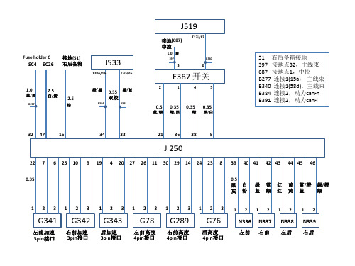
0.35 x2
E387
687 接地点 1
x4 x2 x4
接地点 51
J250
0.5 0.35
x6 x6 x2 x2
x6 x2
x2
J250
SC4: 刹车灯开关 F 5A 端子15 SC26: 后遮阳帘开关和 控制单元 10A 端子15
18、19、20、21、28、 38未占用
– Note installation position of front left body acceleration sender -G341- on bracket. Lug of bracket -1- must engage in recess in front left body acceleration sender -G341--arrowNoteMake sure to use correct bracket. An “L” is punched into bracket. Specified torques Component Specified torque Front left body acceleration sender -G341- to bracket 5 Nm
B391
51 右后备箱接地 397 接地点32,主线束 687 接地点1,中控 B277 连接1(15a),主线束 B340 连接1(58d),主线束 B384 连接2,动力can-h B391 连接2,动力can-i
0.5
蓝/绿 绿
0.35
绿/黑 黑
0.35
绿
0.35
黑/白 白
32
47
16
34
33
21
36
深圳市欣锐特科技有限公司
深圳市欣锐特科技有限公司DC—DC自然风冷变换器规格书产品编号:版本号:拟制:审核:批准:客户确认公司地址:深圳市南山区西丽镇红花岭工业北园A4栋东6楼。
工厂地址:深圳市宝安区石岩街道宏发工业园17栋2楼。
电话:网址:变更履历表变更内容描述变更日期变量号版本变更前变更后1.0 初次发行-- 2014.6 --目录一、DC—DC变换器物理要求1.机械结构安装2.电器链接二、DC—DC变换器电器规格1.产品概述及应用范围2.输入特性3.输出特性4.保护功能5.环境要求6.安规标准7.机械结构参数一、DC—DC变换器物理要求1.机械结构安装注意事项:此DC-DC变换器为隔离式的电源产品,禁止用户自行拆装,以免发生电击危险或高温烫伤。
如有必要:请务必联系供应商进行处理或咨询。
DC-DC变换器总成外部的散热器上总共有8个φ8.5*3.5的安装定位孔,用来与整车车体的连接固定。
安装前请确认整车车体上的8个固定架的水平度,防止其高度不一致在强制增加扭力进行固定时,散热器有可能因受力过大发生变形而损坏DC-DC变换器总成。
2.电气连接本产品所有的连接都是通过接插件实现的。
表1位接插件型号,图2为接插件管脚定义。
按照管脚定义制作相应的插头线束,插入DC-DC 上的插座即可完成 DC-DC 的电气连接。
位置插座型功能厂家对应插D RT00128PN038芯控制信号插座安费诺精密连接器有限公司RT06128SNHEC03E CT34E-1ZJ(RE)-02DCDC 输出正极中航光电科技股份有限公司CT34E-1TK(RE)-01MF CT34E-1ZJ(BK)-02DCDC输出负极中航光电科技股份有限公司CT34E-1TK(BK)-01MGC10514N1-02-3-1G002直流高压插座中航光电科技股份有限公司C10514N1-02-1-2G001表1d e f gRT00128PN03CT34E-1ZJ(RE)-02CT34E-1ZJ(BK)-02C10514N1-02-3-1G002接口定义接口定义接口定义接口定义A、CAN-H 输出正极输出负极+、输入正(+)B、CAN —、输入负(—)C、NCD、NCE、NCF、VCC+工作电源G、VCC-H、NCX、防错齿图2二、DC-DC电气规格1.产品概述及应用范围本DC-DC变换器适用于混合动力及纯电动车型。
隔离器接线
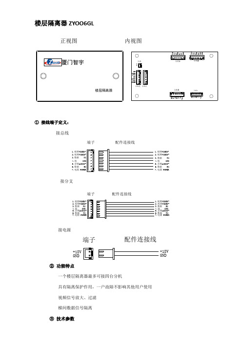
楼层隔离器ZYOO6GL正视图 内视图电源+-总线进POWERD-RX AUDIO GND D-TX VIDEO GND 总线出G N DV +R 1G N D A +T 1+18V 分机1分机2G N DV 2+R 2G N D A +T 2+18V 分机3分机4G N D V 3+R 3G N D A +T 3+18VG N D V 4+R 4G N D A +T 4+18V厦门智宇楼层隔离器① 接线端子定义:接总线端子配件连接线1.视频VIDEO-2.视频VIDEO+3.数据 TX4.地 GND5.音频AUDIO+6.数据 RX7.电源 POWER1.视频VIDEO-2.视频VIDEO+3.数据 TX4.地 GND5.音频AUDIO+6.数据 RX7.电源 POWER接分支7.电源 POWER6.数据 TX 5.音频AUDIO+4.地 GND 3.数据 RX 2.视频VIDEO+1.视频VIDEO-配件连接线端子7.电源 POWER6.数据 TX 5.音频AUDIO+4.地 GND 3.数据 RX 2.视频VIDEO+1.视频VIDEO-接电源+18V GND配件连接线端子+18V GND② 功能特点一个楼层隔离器最多可接四台分机具有隔离保护作用,一户故障不影响其他用户使用 视频信号放大、过滤 梯间数据信号隔离③ 技术参数工作电压:DC 18V±10%工作电流:<30mA安装尺寸:140×80×50mm(长×宽×高)表面尺寸:146×86×55mm(长×宽×高)。
德勒控股 电缆分支箱安装、使用与维护手册说明书

高压成套元器件High-voltage Components GLOBALElectrical SystemsD X N-Q德勒控股集团德勒控股集团德勒控股集团德勒控股集团L-3户内高压带电显示器JSY-Ⅰ注:反向电磁锁要定做CG5-10Q/95×130(130.140.145.150)4-M10VS1-3150A 触臂材料:紫铜硫化处理(注:该型触臂为加长型,适用于大电流隔离车)VS1-4000A 触臂材料:紫铜硫化处理E ECL2601488105240330962425C10-9X19C外形及安装尺寸型号规格L E C JN15-12/31.5-150JN15-12/31.5-210JN15-12/31.5-27553565581015021027539651664627527575810185软连接两孔距L=400mm20-9X19969696主轴母线解触头4060404-φ113271101736462025170701602303558858240R 277外形及安装尺寸主要技术参数外型及安装尺寸使用场所低压使用场所电容使用场所配电(S)注:1、虚线框为计数器显示部分的外形尺寸,此图为柜门正面图;2、只需在柜门上开三个安装孔(3-Φ3.4)和一个信号线插件孔Φ21;3、将计数器背面的三个安装孔与柜门上开的三个安装装孔一一对应,然后在柜门内侧用自攻螺丝拧紧,信号连接线插头通过Φ21的孔插入计数器背面的信号线插件孔中。
TBP系列三相四相组合式过电压保护器(组合式避雷器)6KV、10KV、35KV接线端子示意图24.724132LL10-W 安装支架外形尺寸138.325050138.320LL10-W 灯体LL10-W 安装支架装配好的LL10-W可通过卡脚或螺钉装配。
装配时先固定安装支架,外形及安装尺寸图外形图199139118单位:mm注意:本产品需在柜门上开具尺寸为179±0.5mm 图)作为固定本产品用。
DC DC 转换器 URB_YMD-20WR3 系列说明书
DC/DCConverterURB_YMD-20WR3Series
20WisolatedDC-DCconverterDIPpackage,Ultra-wideinputandregulatedsingleoutput
CBPatentProtectionRoHS
FEATURESUltra-wide4:1inputvoltagerangeHighefficiencyupto91%I/Oisolationtestvoltage1.5kVDCInputunder-voltageprotection,outputshortcircuit,over-current,over–voltageprotectionOperatingambienttemperaturerange-40℃to+105℃
Inputreversepolarityprotectionavailablewithchassis(A2S)or35mmDIN-railmounting(A4S)versionIEC62368,UL62368,EN62368approvedE
URB_YMD-20WR3seriesofisolatedDC-DCconverterproductsfeatureanultra-wide4:1inputvoltagewithefficiencyofupto91%,1500VDCinputtooutputisolation,anoperatingambienttemperaturerangeof-40℃to+105℃,inputunder-voltageprotection,outputover-voltage,overcurrent,shortcircuitprotection,whichmakesthemwidelyusedinindustrialcontrol,electricpower,instrumentsandcommunicationsapplications.OptionalpackagesareofferedforchassisorDIN-railmounting(A2S,A4S),addingadditionalinputreversepolarityprotection.
上海英威达(四川海德电气)使用说明书
16
七、试运行
17
(1)、 运 行前检 查
17
(2)、 试 运行方 式
17
八、功能一览表
18
九、功能说明
23
十、保养维护、故障信息及排除方法
63
(1)、 保 养检查 注 意事项
63
(2)、 定 期检查 项 目
63
(3)、 故 障信息 及 排除方 法
63
(4)、 故 障及分 析
65
十一、周边设施选用及配置
危险 ● 变频器送电中请勿取下前盖,以防止感电受伤。 ● 在开启故障再启动之功能时,马达在运转停止后会自动再启动,请勿靠近 机器,以免发生意外。 ● 停止开关的功能须设定才有效,与紧急停止开关的用法不同,请注意使用。
! 注意 ● 散热座,刹车电阻等发热元件请勿触摸,以防止烫伤。 ● 变频器可以很容易从低速到高速运转,请确认马达与机械的速度容许范围。 ● 变频器运转中请勿检查电路板上的信号,以免发生危险。 ● 变频器于出厂时均已调整设定,请不要任意加以调整,按所需功能适当调
制 键盘设定方式 可直接以← ∧ ∨ 设定
模拟设定方式 外部电压0-5V,0-10V,4—20mA,0—20mA。
其它功能 频率下限,启动频率,停车频率、三个跳跃频率可分别设定
加减速控制 4段加减速时间(0.1-6500秒)任意选择
V /F曲 线
可 任 意 设 定V /F曲 线
转矩控制 可设定转矩提升,最大10.0%启动转矩在1.0Hz时可达150%
! 注意
● 请勿对变频器内部的零部件进行耐压测试,这些半导体零件易受高压损毁。 ● 绝不可将变频器输出端子U.V.W连接至交流电源。 ● 变频器主电路板CMOS、IC易受静电影响及破坏,请勿触摸主电路板。 ● 只有合格的专业人员才可以安装、调试及保养变频器。 ● 变频器报废请按工业废物处理,严禁焚烧。
E-3000控制器使用说明书
E3000控制器使用说明书目录1. 安全上的注意事项、标记....................................P. 22. 特征......................................................P. 43. 规格及外观图..............................................P. 44. 系统结构..................................................P. 65. 扭力输出特性图............................................P. 76. 各部分的名称..............................................P. 97. 保险丝的更换方法..........................................P.118. 托架及橡胶垫脚的安装方法..................................P.119. 电源线的连接方法..........................................P.1310. 马达线的连接方法..........................................P.1311. 风管的连接方法............................................P.1412. 操作方法..................................................P.1513. 外部输入/输出连接器.......................................P.1814. 保护功能..................................................P.2715. 参数的设定方法............................................P.2916. 试运转方法................................................P.3717. 故障的原因及对策..........................................P.38非常感谢您此次购买E3000控制器。
三相交流电流隔离变送器使用说明书
三相交流电流隔离变送器使用说明书CE-IJ31-**BS3-0.51 简介本产品为三相交流电流隔离变送器,采用电磁隔离原理,能够测量三相交流电流信号隔离并线性输出各种可选择的标准信号。
该产品广泛应用于通讯、电力、铁路、工业控制等领域交流电流信号的实时检测/监控。
产品具有如下特点:¾ 安装、接线方便;¾ 精度高,体积小、温漂低;¾ 三相电流相互独立;¾ 产品可靠性高;¾ 可根据客户需求量身定制各种特殊产品。
2 产品外形*输出量:电压、电流、频率、跟踪量*辅助电源:12VDC、15VDC、24VDC*精度等级:0.5 级*负载能力:负载≥2KΩ(电压输出);负载≤250Ω(电流输出)*温漂:≤500ppm/℃*隔离耐压:≥2500 V DC*响应时间:≤300 mS*额定功耗:电压输出0.5 瓦;电流输出2瓦*工作环境:温度:-10~60℃;湿度:≤95%(不结露)5 产品接线示例图(仅供参考,实际应用以产品上的接线图为准)6 安装方式图2产品接线示例图产品采用DIN35 导轨式安装或螺钉固定安装,其安装尺寸如图7所示(单位m m)。
3 产品型号图1产品外形图7 产品的使用7.1 安装图3安装尺寸图4 主要技术指标测试条件:室温:25℃。
*输入范围:0~1AAC~30AAC7.1.1 导轨安装方法:①把变送器固定卡槽一侧勾在安装导轨上;②向下牵动弹簧销;③使变送器卡口套在安装导轨上;④松开弹簧销,变送器卡在安装导轨上。
7.1.2 螺钉安装方法:①按图3所示的尺寸在固定板上打直径为3mm 孔;②使用Φ3 的螺钉插入孔中固定。
7.2 产品出厂时,已按《产品标准》准确调定,确定接线无误后即可通电工作。
7.3 产品的接线端子所能容纳的最大线径为2mm(线号范围16-26AWG),安装线端部的绝缘层剥去4mm~5mm,插入接线端子中,旋紧螺钉。
7.4 产品的辅助电源要求隔离电压≥2000V AC,交流纹波<10mV,多只变送器可以共用一组电源;但电源回路不能再应用于驱动继电器等能产生尖峰脉冲的负载,以免传导干扰信号Io:如输出为4-20mA,则I z = 4+I÷300×16mA;如输出为0-20mA,则I z = I÷300×20mA;8.6 用输出监测表测量直流电压输出值V o 或电流输出值8.7 重复执行4、5 两条操作,所得到的各个点│V o-Vz│到变送器。
- 1、下载文档前请自行甄别文档内容的完整性,平台不提供额外的编辑、内容补充、找答案等附加服务。
- 2、"仅部分预览"的文档,不可在线预览部分如存在完整性等问题,可反馈申请退款(可完整预览的文档不适用该条件!)。
- 3、如文档侵犯您的权益,请联系客服反馈,我们会尽快为您处理(人工客服工作时间:9:00-18:30)。
DC-9503E隔离器安装手册
摘要:
DC-9503E隔离器是一款用于隔离高压电源系统及高压电路的中继式金属氧化物半导体隔离器,用于保护负载和检测电源系统工作状况。
DC-9503E隔离器具有结构简单,控制可靠,集成便捷等优点。
本文介绍了DC-9503E隔离器的安装步骤,以及安装过程中应注意的注意事项。
关键词:DC-9503E隔离器;安装;步骤
一、DC-9503E隔离器安装概述
DC-9503E隔离器是一款采用中继式金属氧化物半导体(MOSFET)控制的隔离开关,可以有效地防止被保护的负载因其他电路受到干扰而出现故障,并可以提供高压开关保护功能。
因此,DC-9503E隔离器在高压电源系统及高压电路中都有其重要应用。
二、DC-9503E隔离器安装步骤
(一)安装前准备
1、根据DC-9503E隔离器的安装环境及其要求,确定安装现场,并准备安装所需的安装工具及工具。
2、根据DC-9503E隔离器的技术要求,确定安装位置及安装方式。
3、确定DC-9503E隔离器的输入电源,并准备输入电源连接线材及连
接安装件。
4、确定安装完成后的动作及保护配置。
(二)安装隔离器
1、将DC-9503E隔离器固定在安装表面,使隔离器安装位置准确无误。
2、连接DC-9503E隔离器的输入电源,并将连接线材与DC-9503E隔
离器进行完全连接。
3、将DC-9503E隔离器的输入电源连接到电源系统,并与受保护的负
载以及相关系统进行相连接,确保DC-9503E隔离器可以安全运行。
4、如有需要,安装完成后可以对DC-9503E隔离器所安装的地方标示
出警示牌,以提醒操作人员注意安全。
三、安装时注意事项
1、安装前应根据使用环境和技术要求进行检查,确保安装
正确、安全,以及DC-9503E隔离器能够满足应用需要。
2、安装过程中应认真履行安全操作程序,并确保操作人员拥有足够的
安全教育和实践能力。
3、DC-9503E隔离器安装完成后,需要对其进行安全检查,确保隔离器可以安全、可靠地控制电路。
4、应有专业的技术人员定期检查DC-9503E隔离器,定期进行性能检查和维护保养,以确保DC-9503E隔离器的稳定、可靠操作。