Fatigue crack growth behaviour and life prediction for 2324-T39 and 7050-T7451 aluminium alloys
【国家自然科学基金】_fatigue life_期刊发文热词逐年推荐_20140730
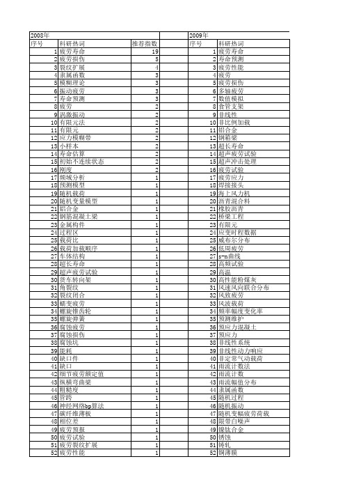
混凝土梁 混凝土 涂层 海洋平台 波浪载荷 沥青用量 沉头螺钉 残余应力 模糊累积损伤miner法则 棘轮行为 桥面焊接细节 栓钉 标准日应力谱 材料表面与界面 有限元/无单元伽辽金方耦合 最优设计 时间相关 日应力谱 无黏结预应力 断裂力学 改性沥青 损伤演化 损伤模型 损伤度 损伤 振动疲劳 扩展路径 悬架系统 性能退化 微弧氧化 循环变形 强化作用 应力集中系数 应力集中 应力场 应力分布 幅值分布 屈服平台 局部增强 小梁疲劳试验 室温 完全叠接管节点 孪晶界 多轴 多体动力学模型 外推插值法 塔架 四阶矩法 喷丸 可靠性 可靠度评价 变换规律 变幅加载 反对称犬骨连接
疲劳应力 疲劳寿命预测 电阻法 电子技术 焊接接头 灵敏度分析 灰色系统理论 灰色模型 混凝土 海洋立管 沥青混合料 汽车主减速器 正弦屈曲 模塑封材料 模型试验 机翼 有机玻璃 有效应力强度因子范围门槛值 曲轴 旋转钻井 断裂力学 搅拌摩擦焊 接触应力 损伤 微动疲劳 弹塑性有限元法 开孔 寿命 学习样本 多轴低周疲劳 多裂纹 多腐蚀损伤 多体系统 多体动力学 复合材料层合板 复合材料 塑性应变增长率 受压疲劳 反向传播神经网络 参数估计 历史数据 半圆弯曲试验 动应力 加权最小二乘法 功率谱密度 剥蚀 分布函数 内裂纹 内流 主成分分析 两轴疲劳 三参数威布尔分布 s-n曲线 miner法则
பைடு நூலகம்
107 108 109 110 111
mcevily模型 gh4169合金 fe-safe apdl ansys
1 1 1 1 1
107 108 109 110 111 112 113 114 115 116 117 118 119 120 121 122 123 124 125 126 127 128 129 130 131 132 133 134 135 136 137 138 139 140 141 142 143 144 145 146 147 148 149 150 151 152 153 154 155 156 157 158 159 160
Q345R钢的Ⅰ-Ⅱ复合型疲劳裂纹扩展行为

Q345R钢的Ⅰ-Ⅱ复合型疲劳裂纹扩展行为涂文锋;高增梁;胡兆吉【摘要】It was difficult to predict the law of crack growth path because of changing the stress state constantly on mixed-ode fatigue crack front. However,the crack growth path affected the fatigue crack growth rate directly,thus affecting the crack residual life evaluation and structure safety. The experiments of Ⅰ - Ⅱ mixed-mode fatigue crack growth were conducted with compact tension-shear (CTS) specimens made of Q345R steel under three step loading condition. Using a two-dimensional optical position measuring system, real-time tracking and accurate positioning of the crack front were conducted to calculate the fatigue crack length. The use of dynamic material testing machine may automatically calculate the loading cycle number. According to the relationship of the crack length and loading cycles, the corresponding crack growth rate could be obtained using seven point incremental polynomial fitting method. After the end of the experiment,the clear Ⅰ -Ⅱ mixed-mode fatigue crack growth path could be got by using high power electron microscope. The results showed that asymmetric CTS specimens experienced the mixed Mode Ⅰ - Ⅱ loading condition;crack growth direction was changed constantly,and was influenced by the loading angle mainly. After changing the loading direction,crack growth path was perpendicular to the loading direction approximately or crossing; crack growth rate decreased rapidly, presenting the overload retardation phenomenon.%复合型疲劳裂纹前沿多轴应力状态不断变化,裂纹扩展路径的走向难于预测;然而裂纹扩展路径直接影响裂纹扩展速率,从而影响裂纹体剩余寿命的准确评估和结构的安全性.在分步加载下,采用不同厚度的Q345R钢非对称紧凑拉剪(CTS)试样,进行Ⅰ-Ⅱ复合型疲劳裂纹扩展行为的实验研究.采用二维光学定位测量系统,实时跟踪和准确定位裂纹前沿,计算疲劳裂纹扩展长度;利用动态材料疲劳试验机,可以自动记录加载循环次数;根据裂纹扩展长度与循环次数的关系,采用七点递增多项式拟合方法,可以得到相对应的裂纹扩展速率.实验结束后,采用高倍电子显微镜拍照,可得到清晰的Ⅰ-Ⅱ复合型疲劳裂纹扩展路径.实验结果表明:非对称CTS试样一直经历Ⅰ-Ⅱ复合型疲劳裂纹扩展,裂纹扩展路径不断发生改变,偏斜程度主要受到加载角度的影响;加载方向改变后,裂纹扩展路径有向外载荷垂线方向靠近或跨越的趋势,裂纹扩展速率迅速下降,表现为过载延迟现象.【期刊名称】《南昌大学学报(理科版)》【年(卷),期】2012(036)006【总页数】6页(P537-542)【关键词】裂纹扩展路径;裂纹扩展速率;加载角度;偏斜角度;试样厚度【作者】涂文锋;高增梁;胡兆吉【作者单位】南昌大学环境与化学工程学院,江西南昌 330031;浙江工业大学化工机械研究所,浙江杭州 310032;南昌大学环境与化学工程学院,江西南昌 330031【正文语种】中文【中图分类】O346.2实际工程结构通常承受拉压、剪切和扭转等复合加载,复合型疲劳裂纹前沿多轴应力状态不断发生变化,裂纹扩展路径表现为不自相似(Non-selfsimilar)的扩展特性。
An Elastoplastic Damage Constitutive Model for Concrete

170
LIU Jun et al. / China Ocean Eng., 27(2), 2013, 169 − 182
account. As well known, the irreversible deformation in concrete is closely related to microcracks. The growth and coalescence of microcracks lead to the degradation of stiffness and strength, while interfaces deterioration of microcracks results in incomplete closure after unloading. Therefore, these two theories should be combined, as have been researched by many scholars in various ways. In their research, plasticity can be described in effective stress space (weak coupling) (Lee and Fenves, 1998; Jason et al., 2006), or nominal stress space (strong coupling) (Lubliner et al., 1989; Salari et al., 2004; Kratzig and Polling, 2004), while damage can be described based on isotropic (scalar) (Mazars and Pijaudier-Cabot, 1989; Hassler-Combe and Hartig, 2008) or anisotropic (tensor) (Skrzypek and Ganczarski,1998; Meschke et al., 1998; Voyiadjis et al., 2008) idealization. In order to enhance the numerical efficiency and reflect the nonlinear feature of concrete as well as possible, in the presented research, plasticity is formulated in effective stress space, and isotropic hardening has been taken into account. Besides that, two scalar indicators of tensile damage and compressive damage are introduced to establish strict constitutive model that ensure thermodynamic consistency in describing the different features of concrete under tension and compression. Fully implicit backward-Euler integration algorithm characterized by unconditional stability is employed in the numerical computation. The proposed model is examined firstly by using uniaxial, biaxial and triaxial loading cases, monotonically as well as cyclically. And then, damage process of a double-edge-notched specimen subjected to loading combination of shear and tension is simulated to further verify the model. The tensor product and contractions in this paper are operated by using notational convention as
Fatigue & Fracture of Engineering Materials & Structures

25 1
252
G. P.TlLLY
In practice measured stresses are usually lower than design values. There have been a limited number of field measurements for reinforcement in bridges. Ruhl and Walker [4] measured stresses produced by the passage of a test truck and reported values of up to 103 N/mm2 and 144 N/mm2 for transverse reinforcement in two separate bridge decks. For the types of bar used in such bridges the stress range to give an endurance of 5 . lo6 cycles is quoted as being from 159 to 197 N/mm2. This apparently gives a safe situation but the margin is actually less because fatigue strengths at 10’ cycles can be as much as 25% lower than at 5 . lo6 cycles. Furthermore corrosion can decrease the fatigue strength whilst the dynamic interaction between the superstructure and vehicle can increase the applied stresses. There has been much research into fatigue of reinforcement. This has been intensified in recent years by the introduction of higher strength materials, the development of advanced applications such as offshore structures and the adoption of new design codes. In addition i t is becoming recognised that features such as corrosion, type of bar, form of manufacture, etc. can cause the fatigue lives to be substantially lower than are normally given in reference data. Although attention has been focussed mainly on the reinforcement bars, consideration must also be given to the fatigue performance of concrete in relation to bridges and highway pavements. In addition to a structural role, concrete protects the reinforcement from corrosion. Cracking of the concrete matrix is controlled by the type and spacing of the reinforcement bars. Research work on fatigue of concrete has recently been reviewed by Raithby [5]. There have been excellent reviews of many aspects of the fatigue of reinforcement bars written mainly as aids to the design engineer 16-81. In the review by Menzies [S] it was found that there was a scarcity of data for fatigue of British reinforcement and it was necessary to base design proposals largely on data for European steels. There are difficulties in appraising published data because there are several different types of test; one school of thought favours axial tests on unclad reinforcement in air and another favours bending tests on reinforced concrete beams. Since Menzies’ review a considerable number of investigations have been reported and data have become available for British steels. A number of new investigations have been commenced albeit mainly concerned with marine environments. It is therefore timely to review the current state-of-the-art. This paper is concerned mainly with conditions relevant to concrete structures such as highway bridges. No consideration is given to fracture mechanics partly because there has been comparatively little work relevant to reinforcement and partly because unlike requirements for welded plate bridges detailed knowledge of fracture behaviour is not required for current design practice related to concrete bridges.
18CrNiMo7-6和20CrMnTi材料齿根弯曲疲劳寿命对比

18CrNiMo7-6和20CrMnTi材料齿根弯曲疲劳寿命对比李道军1卢青波2刘德平3(1郑州职业技术学院电气电子工程系,河南郑州450121)(2郑州职业技术学院机械工程系,河南郑州450121)(3郑州大学机械与动力工程学院,河南郑州450001)摘要对比了齿轮钢材料18CrNiMo7-6与20CrMnTi的齿根弯曲疲劳寿命。
基于这两种材料的疲劳特性,采用SolidWorks中的GearTrax插件建立齿轮模型,并通过Workbench对齿轮的轮齿进行静力学分析;将静力学分析结果导入疲劳分析软件FE-SAFE中,结合载荷谱信息对两种材料齿轮进行疲劳寿命计算,得到齿轮的寿命云图并进行了仿真分析比较;通过试验验证了该仿真方法的可行性。
结果表明,在相同的载荷条件下,18CrNiMo7-6齿轮的疲劳寿命大于20CrMnTi齿轮的疲劳寿命,与试验结果较为接近。
该分析结果对工程实践具有一定的指导作用。
关键词疲劳寿命齿轮静力学仿真分析Comparison of Tooth Root Bending Fatigue Life Between18CrNiMo7-6and20CrMnTi MaterialsLi Daojun1Lu Qingbo2Liu Deping3(1Department of Electrical and Electronic Engineering,Zhengzhou Technical College,Zhengzhou450121,China)(2Department of Mechanical Engineering,Zhengzhou Technical College,Zhengzhou450121,China)(3School of Mechanical and Power Engineering,Zhengzhou University,Zhengzhou450001,China)Abstract In order to compare the tooth root bending fatigue life of18CrNiMo7-6and20CrMnTi gears,based on the fatigue characteristics of these two materials,the gear model is built by using the GearTrax plug-in in the3D modeling software SolidWorks.Through the finite element analysis software Workbench,the statics analysis of the single tooth of the gear is performed,and then the static analysis result is introduced into the fa⁃tigue analysis software FE-SAFE,in combination with the load spectrum information,the fatigue life of the two gears are calculated,and the obtaining life cloud maps are analyzed and compared.The feasibility of the simula⁃tion method is verified by experiments.The results show that,under the same load conditions,the fatigue life of gears with18CrNiMo7-6is slightly greater than that with20CrMnTi,it is close to the experimental results.The analysis results have a certain guiding role for engineering practice.Key words Fatigue life Gear Statics Simulation analysis0引言齿轮在机械传动领域有着举足轻重的地位,在各种机械装备中主要承担传动任务。
实验室加速腐蚀环境下7050-T7451厚板疲劳性能研究

实验室加速腐蚀环境下7050-T7451厚板疲劳性能研究张红飞;赵连红;王浩伟【摘要】目的研究两种应力集中系数7050厚板铝合金材料在腐蚀环境下的腐蚀疲劳性能.方法开展7050厚板铝合金材料在3.5%NaCl盐水和油箱积水两种环境下的腐蚀疲劳实验,采用三参数式进行S-N曲线拟合分析不同应力集中系数、不同腐蚀环境对7050厚板铝合金材料疲劳性能的影响.结果腐蚀环境和应力集中系数都会对7050厚板铝合金材料的疲劳性能有影响,3.5%NaCl盐水和油箱积水两种腐蚀环境相较于应力集中系数对于降低材料疲劳性能的影响更大.结论减少7050厚板铝合金应力集中系数,加强7050厚板铝合金材料腐蚀防护对于提高材料抗疲劳性能有显著作用.【期刊名称】《装备环境工程》【年(卷),期】2019(016)001【总页数】5页(P77-81)【关键词】7050厚板铝合金材料;应力集中系数;腐蚀环境;疲劳性能【作者】张红飞;赵连红;王浩伟【作者单位】中国特种飞行器研究所结构腐蚀防护与控制航空科技重点实验室,湖北荆门 448035;中国特种飞行器研究所结构腐蚀防护与控制航空科技重点实验室,湖北荆门 448035;中国特种飞行器研究所结构腐蚀防护与控制航空科技重点实验室,湖北荆门 448035【正文语种】中文【中图分类】TG1727050铝合金材料的高抗剥落腐蚀性等诸多优点[1-2]在航空制造使用中发挥着重要作用。
通常以中厚板挤压件、自由锻件与模锻件的形式运用到飞机结构中。
随着飞机在沿海地区和海域的服役机会逐渐增多,长期的高盐雾、高湿热等严酷海洋环境极易引起7050铝合金材料腐蚀,同时作为主承力结构的7050厚板铝合金材料在应力和腐蚀环境双重作用易发生腐蚀疲劳损伤,导致结构腐蚀破坏,直接影响飞机安全和可靠性[3-5]。
李鸿鹏[6]在研究铝合金腐蚀疲劳进展中指出疲劳(裂纹)损伤占飞机各类机械损伤总数的30%,飞机结构在飞机服役过程中,在承受交变载荷作用的同时,会遭受不同腐蚀因素长期腐蚀作用,使飞机结构寿命大幅度降低。
fatigue寿命
Fatigue疲劳分析操作流程文中所给疲劳计算流程分为三步,分别是结果文件导入,疲劳分析参数设置与求解运算和结果。
1.结果文件的导入点击File/New进入文件新建界面,如图1所示。
图中查找范围给定文件存储路径,文件名指定文件的名称,文件名和存储路径确定后点击OK即建立fatigue分析文件。
图1点击Prefereces/Analysis,进入有限元结果文件导入格式设置界面,如图2所示。
因为弛张筛有限元分析选择了abaqus软件,所以analysis code要选择abaqus,其他设置按默认,点击OK完成abaqus结果文件导入格式设置。
图2点击analysis进入有限元结果文件导入界面,如图3所示。
Action选择read results,object选择both,mothed选择translate,点击select results file,随即弹出文件选择界面,如图4,选择目标结果文件按确定进行文件导入。
图3图42.疲劳分析参数设置点击tools/msc fatigue/main interface进入疲劳分析界面,如图5所示,analysis选择s-n,分别给定jobname和title名称,然后进行载荷谱和材料以及计算方法的设置。
点击loading information进入载荷谱设定界面,如图6。
点击Time history manager来设置时间历程,随即进入时间历程设置界面,如图7选择copy from centre点击OK,选择图8所示标识进入时间历程加载库,最后选择图9所示SINE01点击OK完成时间历程函数的选取。
当然,所选取的函数是标准时间历程函数,所以还需要对原函数的设置进行修改。
如图10选择change an entry进入时间历程函数设置界面。
图5图6图7图8图9图10退回到载荷谱设置界面。
点击Load Case ID下空格/(Get/Fitter Results)进入载荷设置界面,如图11勾选select all results cases点击apply退出,这时Select a Results Load Case栏中出现稳态动力学载荷,如图12选择应力部分,这样便导入了应力计算结果。
A fracture-resistant high-entropy alloy for cryogenic applications
DOI: 10.1126/science.1254581, 1153 (2014);345 Science et al.Bernd Gludovatz A fracture-resistant high-entropy alloy for cryogenic applicationsThis copy is for your personal, non-commercial use only.clicking here.colleagues, clients, or customers by , you can order high-quality copies for your If you wish to distribute this article to othershere.following the guidelines can be obtained by Permission to republish or repurpose articles or portions of articles): September 13, 2014 (this information is current as of The following resources related to this article are available online at/content/345/6201/1153.full.html version of this article at:including high-resolution figures, can be found in the online Updated information and services, /content/suppl/2014/09/03/345.6201.1153.DC1.html can be found at:Supporting Online Material /content/345/6201/1153.full.html#ref-list-1, 2 of which can be accessed free:cites 45 articles This article/cgi/collection/mat_sci Materials Sciencesubject collections:This article appears in the following registered trademark of AAAS.is a Science 2014 by the American Association for the Advancement of Science; all rights reserved. The title Copyright American Association for the Advancement of Science, 1200 New York Avenue NW, Washington, DC 20005. (print ISSN 0036-8075; online ISSN 1095-9203) is published weekly, except the last week in December, by the Science o n S e p t e m b e r 13, 2014w w w .s c i e n c e m a g .o r g D o w n l o a d e d f r o mdid not observe the formation of any well-defined structures in the absence of an applied magnetic field (see,e.g.,fig.S8J).24.A.Dong et al .,Nano Lett.11,841–846(2011).25.S.Brooks,A.Gelman,G.Jones,X.-L.Meng,Handbook of Markov Chain Monte Carlo (Chapman &Hall,London,2011).26.Z.Kakol,R.N.Pribble,J.M.Honig,Solid State Commun.69,793–796(1989).27.Ü.Özgür,Y.Alivov,H.Morkoç,J.Mater.Sci.Mater.Electron.20,789–834(2009).28.The formation of helices,and the self-assembly of NCs in our system in general,is likely facilitated by entropic forces;OA used in large excess during self-assembly may act as adepletion agent,inducing crystallization of NCs during hexane evaporation as reported previously (29).29.D.Baranov et al .,Nano Lett.10,743–749(2010).30.On the basis of measurements of electrophoretic mobility [see (34)]and the lack of literature reports on electric dipole moments of magnetite nanoparticles,we did not considerelectrostatic and electric dipole-dipole interactions in our analysis of interparticle interactions.At the same time,we cannot exclude 31.S.Srivastava et al .,Science 327,1355–1359(2010).32.S.Das et al .,Adv.Mater.25,422–426(2013).33.J.V.I.Timonen,tikka,L.Leibler,R.H.A.Ras,O.Ikkala,Science 341,253–257(2013).34.Previous self-assembly experiments performed in nonpolarsolvents excluded a significant role played by electrostatic interactions [e.g.,(35,36)].Although the degree ofdissociation of OA in hexane (dielectric constant =1.84)is negligible,the large excess of OA as well as the nature of our experimental setup (self-assembly at the liquid-air interface)might potentially promote dissociation of OA;to verify this possibility,we used a Malvern Zetasizer Nano ZS to perform electrophoretic mobility (m e )measurements of our nanocubes in hexane both in the absence and in the presence of additional OA (5%v/v).The results [0.00706(T 0.00104)×10−4cm 2V –1s –1and 0.0218(T 0.00710)×10−4cm 2V –1s –1,respectively]indicate that in both cases,the nanocubes are essentially neutral [compare with (37)].35.Z.Chen,J.Moore,G.Radtke,H.Sirringhaus,S.O ’Brien,J.Am.Chem.Soc.129,15702–15709(2007).37.S.A.Hasan,D.W.Kavich,J.H.Dickerson,mun.2009,3723–3725(2009).ACKNOWLEDGMENTSSupported by Israel Science Foundation grant 1463/11,theG.M.J.Schmidt-Minerva Center for Supramolecular Architectures,and the Minerva Foundation with funding from the Federal German Ministry for Education and Research (R.K.)and byNSF Division of Materials Research grant 1309765and American Chemical Society Petroleum Research Fund grant 53062-ND6(P.K.).SUPPLEMENTARY MATERIALS/content/345/6201/1149/suppl/DC1Materials and Methods Figs.S1to S28References (38–92)31March 2014;accepted 14July 2014Published online 24July 2014;METAL ALLOYSproperties required for structural applica-tions.Consequently,alloying elements are added to achieve a desired microstructure or combination of mechanical properties,such as strength and toughness,although the re-sulting alloys invariably still involve a single dom-inant constituent,such as iron in steels or nickel in superalloys.Additionally,many such alloys,such as precipitation-hardened aluminum alloys,rely on the presence of a second phase for me-chanical performance.High-entropy alloys (1–3)represent a radical departure from these notions.they contain high concentrations (20to 25atomic percent)of multiple elements with different crystal structures but can crystallize as a single phase (4–7).In many respects,these alloys rep-resent a new field of metallurgy that focuses attention away from the corners of alloy phase diagrams toward their centers;we believe that as this evolving field matures,a number of fas-cinating new materials may emerge.The CrMnFeCoNi alloy under study here is a case in point.Although first identified a decade ago (1),the alloy had never been investigated mechanically until recently (5,6,8),yet is clearly scientifically interesting from several perspec-tives.It is not obvious why an equiatomic five-element alloy —where two of the elements (Cr and Fe)crystallize with the body-centered cubic (bcc)structure,one (Ni)as face-centered cubic (fcc),one (Co)as hexagonal close-packed (hcp),and one (Mn)with the complex A 12structure —should form a single-phase fcc structure.Fur-thermore,several of its properties are quite unlike those of pure fcc metals.Recent studies indicatethat the alloy exhibits a strong temperature de-of the yield strength between ambient cryogenic temperatures,reminiscent of bcc and certain fcc solid-solution alloys (6).any temperature-dependent effect of rate on strength appears to be marginal (6).the marked temperature-dependent in strength is accompanied by a substan-increase in tensile ductility with decreasing between 293K and 77K (6),which counter to most other materials where an dependence of ductility and strength is seen (9).Preliminary indications sug-that this may be principally a result of the ’s high work-hardening capability,possi-associated with deformation-induced nano-which acts to delay the onset of any instability (i.e.,localized plastic deforma-that can lead to premature failure)to higher (5).We prepared the CrMnFeCoNi alloy with high-elemental starting materials by arc melting drop casting into rectangular-cross-section copper molds,followed by cold forging and cross rolling at room temperature into sheets roughly 10mm thick.After recrystallization,the alloy had an equiaxed grain structure.Uniaxial tensile spec-imens and compact-tension fracture toughness specimens in general accordance with ASTM standard E1820(10)were machined from these sheets by electrical discharge machining.[See (11)for details of the processing procedures,sam-ple sizes,and testing methods.]Figure 1A shows a backscattered electron (BSE)micrograph of the fully recrystallized micro-structure with ~6-m m grains containing numer-ous recrystallization twins.Energy-dispersive x-ray (EDX)spectroscopy and x-ray diffraction (XRD)indicate the equiatomic elemental dis-tribution and single-phase character of the al-loy,respectively.Measured uniaxial stress-strain curves at room temperature (293K),in a dry ice –alcohol mixture (200K),and in liquid nitrogen (77K)are plotted in Fig.1B.With a decrease in temperature from 293K to 77K,the yield strength s y and ultimate tensile strength s utsSCIENCE 5SEPTEMBER 2014•VOL 345ISSUE 62011153RESEARCH |REPORTS1Materials Sciences Division,Lawrence Berkeley National Laboratory,Berkeley,CA 94720,USA.2Department of Materials Physics,Montanuniversität Leoben and Erich Schmid Institute of Materials Science,Austrian Academy of Sciences,Leoben 8700,Austria.3Materials Sciences and Technology Division,Oak Ridge National Laboratory,Oak Ridge,TN 37831,USA.4Materials Sciences and Engineering Department,University of Tennessee,Knoxville,TN 37996,USA.5Department of Materials Science and Engineering,University of California,Berkeley,CA 94720,USA.*Corresponding author.E-mail:georgeep@ (E.P.G.);roritchie@ (R.O.R.)increased by ~85%and ~70%,to 759and 1280MPa,respectively.Similarly,the tensile ductility (strain to failure,e f )increased by ~25%to >0.7;the strain-hardening exponent n remained high at ~0.4,such that there was an enhancement in the frac-ture energy (12)by more than a factor of 2.Table S1provides a detailed summary of the stresses and strains at the three different temperatures,as well as the corresponding strain-hardening exponents.In light of the extensive plasticity involved in the deformation of this alloy,we evaluated the fracture toughness of CrMnFeCoNi with non-linear elastic fracture mechanics,specifically with crack-resistance curve (R curve)measurements in terms ofthe J integral.Analogous to the stress intensity K for linear elastic analysis,provided that specific validity criteria are met,J unique-ly characterizes the stress and displacement fields in the vicinity of the crack tip for a non-linear elastic solid;as such,it is able to capture both the elastic and plastic contributions to the fracture process.J is also equivalent to the strain energy release rate G under linear elastic conditions;consequently,K values can be back-calculated from J measurements assuming a mode I equivalence between K and J :specifically,J =K 2/E ´,with E ´=E (Young ’s modulus)in plane stress and E /(1–n 2)(where n is Poisson ’s ratio)in plane strain.E and n values were determined by resonance ultrasound spectroscopy at each tem-perature (13).Our toughness results for the CrMnFeCoNi alloy at 293K,200K,and 77K are plotted in Fig.1C,in terms of J R (D a )–based resistance curves showing crack extension D a in precracked and side-grooved compact-tension specimens as a function of the applied J .Using these R curves to evaluate the fracture toughness for both the initiation and growth of a crack,we measured a crack initiation fracture toughness J Ic ,deter-mined essentially at D a →0,of 250kJ/m 2at 293K,which in terms of a stress intensity gives K JIc =217MPa·m 1/2.Despite a markedly increased strength at lower temperature,K JIc values at 200K and 77K remained relatively constant at K JIc =221MPa·m 1/2(J Ic =260kJ/m 2)and K JIc =219MPa·m 1/2(J Ic =255kJ/m 2),respectively.After11545SEPTEMBER 2014•VOL 345ISSUE SCIENCEFig.1.Microstructure and mechanical properties of the CrMnFeCoNi high-entropy alloy.(A )Fully recrystallized microstructure with an equiaxed grain structure and grain size of ~6m m;the composition is approximately equiatomic,and the alloy is single-phase,as shown from the EDX spectroscopy and XRD insets.(B )Yield strength s y ,ultimate tensile strength s uts ,and ductility (strain to failure,e f )all increase with decreasing temperature.The curves are typical tests at the individual temperatures,whereas the data points are means T SD of multiple tests;see table S1for exact values.(C )Fracture toughness measure-ments show K JIc values of 217MPa·m 1/2,221MPa·m 1/2,and 219MPa·m 1/2at 293K,200K,and 77K,respectively,and an increasing fracture resistance in terms of the J integral as a function of crack extension D a [i.e.,resistance curve (R curve)behavior].(D )Similar to austenitic stainless steels (e.g.,304,316,or cryogenic Ni steels),the strength of the high-entropy alloy (solid lines)increases with decreasing temperature;although the toughness of the other materials decreases with decreasing temperature,the toughness of the high-entropy alloy remains unchanged,and by some measures it actually increases at lower temperatures.(The dashed lines in the plots mark the upper and lower limits of data found in the literature.)RESEARCH |REPORTSinitiation,the fracture resistance further increased with extensive subcritical crack growth;after just over 2mm of such crack extension,a crack growth toughness exceeding K =300MPa·m 1/2(J =500kJ/m 2)was recorded [representing,in terms of ASTM standards,the maximum (valid)crack extension capacity of our samples].Such toughness values compare favorably to those of highly alloyed,austenitic stainless steels such as 304L and 316L,which have reported tough-nesses in the range of K Q =175to 400MPa·m 1/2at room temperature (14–16),and the best cryogenic steels such as 5Ni or 9Ni steels,with K Q =100to 325MPa·m 1/2at 77K (17–19).Similar to the high-entropy alloy,these materials show an expected increase in strength with decreasing temper-ature to 77K;however,unlike the high-entropy alloy,their reported fracture toughness values are invariably reduced with decreasing temperature (20)(Fig.1D)and furthermore are rarely valid (i.e.,they are size-and geometry-dependent and thus not strictly material parameters).The high fracture toughness values of the CrMnFeCoNi alloy were associated with a 100%ductile fracture by microvoid coalescence,with the extent of deformation and necking behavior being progressively lessapparent at the lower temperatures (Fig.2,A and B).EDX analysis of the particles,which were found inside the voids of the fracture surface and acted as initiation sites for their formation,indicated either Cr-rich or Mn-rich compounds (Fig.2B,inset).These particles are likely oxides associated with the Mn additions;preliminary indications are that they are absent in the Mn-free (CoCrFeNi)alloy (6).Both microvoid size and particle size varied markedly;the microvoids ranged in size from ~1m m to tens of micrometers,with particle sizes ranging from <1m m to ~5m m (Fig.2B,inset)with an average size of 1.6m m and average spacing d p ≈49.6m m,respectively.To verify the high measured fracture tough-ness values,we used three-dimensional (3D)ster-eophotogrammetry of the morphology of these fracture surfaces to estimate local crack initia-tion toughness (K i )values for comparison with the global,ASTM-based K JIc measurements.This technique is an alternative means to characterize the onset of cracking,particularly under large-scale yielding conditions.Under mode I (tensile)loading,the crack surfaces completely separate from each other,with the regions of first sepa-ration moving the farthest apart and progres-sively less separation occurring in regions that crack later.Accordingly,the formation and coa-lescence of microvoids and their linkage with the crack tip allow for the precise reconstruction of the point of initial crack advance from the juxta-position of the stereo images of each fracture sur-face.This enables an evaluation of the crack tip opening displacement at crack initiation,CTOD i ,which then can be used to estimate the local stress intensity K i at the midsection of the sample at the onset of physical crack extension,where D a =0(21).Specifically,we used an automatic fracture surface analysis system that creates 3D digital surface models from stereo-image pairs of the corresponding fracture surfaces taken in the scan-ning electron microscope (Fig.2C);digitally re-constructing the crack profiles by superimposing the stereo-image pairs allows for a precise mea-surement of the CTOD i s of arbitrarily chosen crack paths (which must be identical on both fracture surfaces).Figure 2D indicates two examples of the approximately 10crack paths taken on both fracture surfaces of samples tested at 293K and 77K.The two corresponding profiles show the point at which the first void,formed ahead of the fatigue precrack,coalesced with this pre-crack to mark the initial crack extension,there-by locally defining the crack initiation event andSCIENCE 5SEPTEMBER 2014•VOL 345ISSUE 62011155Fig.2.Images of fractured CrMnFeCoNi samples.(A )Stereomicroscopic photographs of the fracture surfaces after testing indicate less lateral defor-mation and necking-like behavior with decreasing temperature.(B )SEM image of the fracture surface of a sample tested at room temperature shows ductile dimpled fracture where the void initiation sites are mainly Mn-rich or Cr-rich par-ticles,as shown by the EDX data (insets).(C )Three-dimensional digital fracturesurface models were derived from SEM stereo-image pairs,which indicate the transition from fatigue precrack to ductile dimpled fracture and the presence of the stretch zone.(D )Profiles of identical crack paths from both fracture halves of the fracture surface models were extracted to evaluate the crack tip opening displacement at the first physical crack extension,CTOD i ,which was then converted to J i using the relationship of the equivalence of J and CTOD (50).RESEARCH |REPORTSthe fracture toughness (22).Using these pro-cedures,the initial crack tip opening displace-ments at crack initiation were found to be CTOD i =57T 19m m at 293K and 49T 13m m at ing the standard J-CTOD equivalence relationship of J i ºs o CTOD i =K i 2/E ´gives es-timates of the crack initiation fracture toughness:K i =191MPa·m 1/2and 203MPa·m 1/2at 293K and 77K,respectively.These values are slightly con-servative with respect to the global R curve –based values in Fig.1C;however,this is to be expected,as theyare estimated at the initial point of physical contact of the first nucleated void with the precrack,whereas the ASTM-based measurements use an operational definition of crack initiation involving subcritical crack ex-tension of D a =200m m.To discern the micromechanisms underlying the excellent fracture toughness behavior,we fur-ther analyzed the fracture surfaces of samples tested at 293K and 77K by means of stereomi-croscopy and scanning electron microcopy (SEM).Some samples were additionally sliced in two halves,embedded,and metallographically pol-ished for BSE microscopy and electron back-scatter diffraction (EBSD)analysis of the region in the immediate vicinity of the crack tip and in the wake of the crack,close to the crack flanks,specifically “inside ”the sample where fully plane-strain conditions prevail.SEM images of the crack tip region of sam-ples tested at ambient and liquid nitrogen tem-peratures show the formation of voids and their coalescence characteristic of the microvoid co-alescence fracture process (Fig.3A).A large population of the particles that act as the void11565SEPTEMBER 2014•VOL 345ISSUE 6201 SCIENCEFig.3.Deformation mechanisms in the vicinity of the crack tip in the center (plane-strain)section of CrMnFeCoNi high-entropy alloy samples.(A )Low-magnification SEM images of samples tested at 293K and 77K show ductile fracture by microvoid coalescence,with a somewhat more distorted crack path at the lower temperature.(B )EBSD images show numerous annealing twins and pronounced grain misorientations due to dislocations —the primary defor-mation mechanism at 293K.(C )At 77K,BSE images taken in the wake of the propagated crack show the formation of pronounced cell structures resulting from dislocation activity.Both BSE and EBSD images show deformation-induced nanotwinning as an additional mechanism at 77K.[The EBSD image is an overlay to an image quality (IQ)map,which is a measure of the quality of the collected EBSD pattern used to visualize certain microstructural features.]RESEARCH |REPORTSinitiation sites can be seen on the fracture surfaces (Fig.2B);these particles have a substan-tial influence on material ductility and likely contribute to the measured scatter in the failure strains (Fig.1B).Macroscopically,fracture sur-faces at 77K appear significantly more deviated from a mode I (K II =0)crack path than at 293K (Fig.3A).Although such deflected crack paths act to reduce the local crack-driving force at the crack tip (23)and hence contribute to the rising R curve behavior (i.e.,crack growth toughness),this mech-anism cannot be responsible for the exceptional crack initiation toughness of this alloy.Such high K i values are conversely derived from the large CTOD s at crack initiation and are associated with the intrinsic process of microvoid coalescence;as such,they are highly dependent on the formation and size of voids,the prevailing deformation and flow conditions,and the presence of steady strain hardening to suppress local necking.Using simple micromechanical models for fracture (24),we can take advantage of a stress state –modified critical strain criterion for ductile fracture to derive estimates for these high tough-ness values (25–27).This yields expressions forthe fracture toughness in the form J Ic ≈s o e f l *o,where s o is the flow stress,e f is the fracture strain in the highly constrained stress state in the vicinity of the crack tip [which is roughly an order of magnitude smaller than the un-iaxial tensile ductility (28)],and l *ois the char-acteristic distanceahead of the tip over which this critical strain must be met for fracture (which can be equated to the particle spacing d p ).Assum-ing Hutchinson-Rice-Rosengren (HRR)stress-strain distributions ahead of a crack tip in plane strain for a nonlinear elastic,power-law hard-ening solid (strain-hardening coefficient of n )(29,30),and the measured properties,specifically E ,s o ,e f ,n ,n ,and d p ,for this alloy (11),estimates of the fracture toughness of K JIc =(J Ic E ´)1/2of ~150to 215MPa·m 1/2can be obtained for the measured particle spacing of d p ~50m m.Although approx-imate,these toughness predictions from the critical fracture strain model are completely consistent with a fracture toughness on the order of 200MPa·m 1/2,as measured for the CrMnFeCoNi alloy in this study (Fig.1C).In addition to crack initiation toughnesses of 200MPa·m 1/2or more,this alloy develops even higher crack growth toughness with stable crack growth at “valid ”stress intensities above 300MPa·m 1/2.These are astonishing toughness levels by any standard,particularly because they are retained at cryogenic temperatures.A primary factor here is the mode of plastic deformation,which induces a steady degree of strain hardening to suppress plastic instabilities;expressly,the mea-sured strain-hardening exponents of n ~0.4are very high relative to the vast majority of metals,particularly at this strength level.Recent studies have shown that,similar to mechanisms known for binary fcc solid solutions (31,32),plastic de-formation in the CrMnFeCoNi alloy at ambienttemperatures is associated with planar glide of 1/2〈110〉dislocations on {111}planes leading to the formation of pronounced cell structures at higher strains (5).However,at 77K,in addition to planar slip,deformation-induced nanoscale twinning has been observed both previously (5)and in the present study (Fig.3C)and contributes to the increased ductility and strain hardening at lower temperatures.Both the planar slip and nanotwinning mechanisms are highly active in the vicinity of the crack tip during fracture,as illustrated in Fig.3.EBSD images taken ahead of the crack tip inside the sample of a fracture toughness test performed at room temperature show grain misorientations resulting from dis-location activity as the only deformation mech-anism (Fig.3B).Aside from numerous annealing twins resulting from the recrystallization step during processing,twinning does not play a role at ambient temperatures,with only a few single nanotwins in evidence.With decrease in tem-perature,cell structure formation is more appar-ent,as shown by the BSE image in Fig.3C,taken in the wake of a crack propagating at 77K.Here,however,excessive deformation-induced nano-scale twinning occurs simultaneously with planar dislocation slip,leading to a highly distorted grain structure,which can be seen in both the BSE and IQ +EBSD images in the vicinity of the growing crack.[The EBSD image is shown as an overlay of an image quality (IQ)map to enhance visual-ization of structural deformations of the grains.]Note that several other classes of materials show good combinations of strength and ductility when twinning is the dominant deformation mecha-nism.These include copper thin films (33–36)and the recently developed twinning-induced plas-ticity (TWIP)steels (37–40),which are of great interest to the car industry as high-Mn steels (41–44).We believe that the additional plasticity mechanism of nanotwinning in CrMnFeCoNi is critical to sustaining a high level of strain hard-ening at decreasing temperatures;this in turn acts to enhance the tensile ductility,which,to-gether with the higher strength at low tem-peratures,preserves the exceptional fracture toughness of this alloy down to 77K.We conclude that the high-entropy CrMnFeCoNi alloy displays remarkable fracture toughness properties at tensile strengths of 730to 1280GPa,which exceed 200MPa·m 1/2at crack initiation and rise to >300MPa·m 1/2for stable crack growth at cryogenic temperatures down to 77K.The alloy has toughness levels that are comparable to the very best cryogenic steels,specifically cer-tain austenitic stainless steels (15,16)and high-Ni steels (17–19,45–48),which also have outstanding combinations of strength and ductility.With respect to the alloy ’s damage tolerance,a comparison with the other major material classes is shown on the Ashby plot of fracture toughness versus yield strength (49)in Fig.4.There are clearly stronger materials,which is understand-able given that CrMnFeCoNi is a single-phase material,but the toughness of this high-entropy alloy exceeds that of virtually all pure metals and metallic alloys (9,49).SCIENCE 5SEPTEMBER 2014•VOL 345ISSUE 62011157Fig.4.Ashby map showing fracture toughness as a function of yield strength for high-entropy alloys in relation to a wide range of material systems.The excellent damage tolerance (toughness combined with strength)of the CrMnFeCoNi alloy is evident in that the high-entropy alloy exceeds the toughness of most pure metals and most metallic alloys (9,49)and has a strength comparable to that of structural ceramics (49)and close to that of some bulk-metallic glasses (51–55).RESEARCH |REPORTSREFERENCES AND NOTES1. B.Cantor,I.T.H.Chang,P.Knight,A.J.B.Vincent,Mater.Sci.Eng.A 375–377,213–218(2004).2.J.-W.Yeh et al .,Adv.Eng.Mater.6,299–303(2004).3. C.-Y.Hsu,J.-W.Yeh,S.-K.Chen,T.-T.Shun,Metall.Mater.Trans.A 35,1465–1469(2004).4.O.N.Senkov,G.B.Wilks,J.M.Scott,D.B.Miracle,Intermetallics 19,698–706(2011).5. F.Otto et al .,Acta Mater.61,5743–5755(2013).6. A.Gali,E.P.George,Intermetallics 39,74–78(2013).7. F.Otto,Y.Yang,H.Bei,E.P.George,Acta Mater.61,2628–2638(2013).8.W.H.Liu,Y.Wu,J.Y.He,T.G.Nieh,Z.P.Lu,Scr.Mater.68,526–529(2013).9.R.O.Ritchie,Nat.Mater.10,817–822(2011).10.E08Committee,E1820-13Standard Test Method forMeasurement of Fracture Toughness (ASTM International,2013).11.See supplementary materials on Science Online.12.As a preliminary estimate of the fracture resistance,thearea under the load displacement curve of a tensile test was used to compute the fracture energy (sometimes termed the work to fracture),which was calculated from this area divided by twice the area of the crack surface.13.J.Maynard,Phys.Today 49,26–31(1996).14.K Q values refer to fracture toughnesses that are notnecessarily valid by ASTM standards (i.e.,they do not meet the J -validity and/or plane strain conditions).Consequently,these toughnesses are likely to be inflated relative to truly valid numbers and are size-and geometry-dependent;they are not strictly material parameters.When comparing these values to the toughnesses measured in this study forCoCrFeMnNi,it is important to note that all values determined here for the high-entropy alloy were strictly valid,meeting ASTM standards for both J validity and plane ls,Int.Mater.Rev.42,45–82(1997).16.M.Sokolov et al .,in Effects of Radiation on Materials:20thInternational Symposium ,S.Rosinski,M.Grossbeck,T.Allen,A.Kumar,Eds.(ASTM International,West Conshohocken,PA,2001),pp.125–147.17.J.R.Strife,D.E.Passoja,Metall.Trans.A 11,1341–1350(1980).18.C.K.Syn,J.W.Morris,S.Jin,Metall.Trans.A 7,1827–1832(1976).19.A.W.Pense,R.D.Stout,Weld.Res.Counc.Bull.205,1–43(1975).20.Note that despite the uncertainty in the (valid)toughnessvalues for the stainless and high Ni steels,their upper toughness range could possibly be higher than the current measurements for the CrMnFeCoNi alloy.It must beremembered,however,that these materials are microalloyed and highly tuned with respect to grain size/orientation,tempering,precipitation hardening,etc.,to achieve their mechanical properties,whereas the current CrMnFeCoNi alloy is a single-phase material that undoubtedly can be further improved through second-phase additions and grain control.21.J.Stampfl,S.Scherer,M.Gruber,O.Kolednik,Appl.Phys.A 63,341–346(1996).22.J.Stampfl,S.Scherer,M.Berchthaler,M.Gruber,O.Kolednik,Int.J.Fract.78,35–44(1996).23.B.Cotterell,J.Rice,Int.J.Fract.16,155–169(1980).24.R.O.Ritchie,A.W.Thompson,Metall.Trans.A 16,233–248(1985).25.A.C.Mackenzie,J.W.Hancock,D.K.Brown,Eng.Fract.Mech.9,167–188(1977).26.R.O.Ritchie,W.L.Server,R.A.Wullaert,Metall.Trans.A 10,1557–1570(1979).27.Details of the critical strain model for ductile fracture (25,26)and the method of estimating the fracture toughness are described in the supplementary materials.28.J.R.Rice,D.M.Tracey,J.Mech.Phys.Solids 17,201–217(1969).29.J.W.Hutchinson,J.Mech.Phys.Solids 16,13–31(1968).30.J.R.Rice,G.F.Rosengren,J.Mech.Phys.Solids 16,1–12(1968).31.H.Neuhäuser,Acta Metall.23,455–462(1975).32.V.Gerold,H.P.Karnthaler,Acta Metall.37,2177–2183(1989).33.M.Dao,L.Lu,Y.F.Shen,S.Suresh,Acta Mater.54,5421–5432(2006).34.L.Lu,X.Chen,X.Huang,K.Lu,Science 323,607–610(2009).35.K.Lu,L.Lu,S.Suresh,Science 324,349–352(2009).36.A.Singh,L.Tang,M.Dao,L.Lu,S.Suresh,Acta Mater.59,2437–2446(2011).37.R.A.Hadfield,Science 12,284–286(1888).38.V.H.Schumann,Neue Hütte 17,605–609(1972).39.L.Remy,A.Pineau,Mater.Sci.Eng.28,99–107(1977).40.T.W.Kim,Y.G.Kim,Mater.Sci.Eng.A 160,13–15(1993).41.O.Grässel,G.Frommeyer,C.Derder,H.Hofmann,J.Phys.IV07,C5-383–C5-388(1997).42.O.Grässel,L.Krüger,G.Frommeyer,L.W.Meyer,Int.J.Plast.16,1391–1409(2000).43.G.Frommeyer,U.Brüx,P.Neumann,ISIJ Int.43,438–446(2003).44.L.Chen,Y.Zhao,X.Qin,Acta Metall.Sin.Engl.Lett.26,1–15(2013).45.D.T.Read,R.P.Reed,Cryogenics 21,415–417(1981).46.R.D.Stout,S.J.Wiersma,in Advances in CryogenicEngineering Materials ,R.P.Reed,A.F.Clark,Eds.(Springer,New York,1986),pp.389–395.47.Y.Shindo,K.Horiguchi,Sci.Technol.Adv.Mater.4,319–326(2003).48.J.W.Sa et al .,in Twenty-First IEEE/NPS Symposium on FusionEngineering 2005(IEEE,Piscataway,NJ,2005),pp.1–4.49.M.F.Ashby,in Materials Selection in Mechanical Design ,M.F.Ashby,Ed.(Butterworth-Heinemann,Oxford,ed.4,2011),pp.31–56.50.C.F.Shih,J.Mech.Phys.Solids 29,305–326(1981).51.C.J.Gilbert,R.O.Ritchie,W.L.Johnson,Appl.Phys.Lett.71,476–478(1997).52.A.Kawashima,H.Kurishita,H.Kimura,T.Zhang,A.Inoue,53.A.Shamimi Nouri,X.J.Gu,S.J.Poon,G.J.Shiflet,J.J.Lewandowski,Philos.Mag.Lett.88,853–861(2008).54.M.D.Demetriou et al .,Appl.Phys.Lett.95,041907,041907–3(2009).55.M.D.Demetriou et al .,Nat.Mater.10,123–128(2011).ACKNOWLEDGMENTSSponsored by the U.S.Department of Energy,Office ofScience,Office of Basic Energy Sciences,Materials Sciences and Engineering Division.All data presented in this article can additionally be found in the supplementary materials.Author contributions:E.P.G.and R.O.R.had full access to theexperimental results in the study and take responsibility for the integrity of the data and the accuracy of the data analysis.The alloys were processed by D.C.and mechanically characterized by B.G.,A.H.,and D.C.Study design,interpretation and analysis of data,and preparation of the manuscript were performed jointly by B.G.,A.H.,D.C.,E.H.C.,E.P.G.,and R.O.R.The authors declare no conflict of interest.SUPPLEMENTARY MATERIALS/content/345/6201/1153/suppl/DC1Materials and Methods Supplementary Text Fig.S1Table S19April 2014;accepted 18July 2014process,representing the initial transfor-mation of a disordered phase into an or-dered one.It is also the most difficult part of the process to observe because it hap-pens on very short time and length scales.In thebate as to whether classical nucleation theory (CNT),as initially developed by Gibbs (1),is a suitable framework within which to describe the process,or whether nonclassical elements such as dense liquid phases (2–4)or (meta)stable clusters (5)play important roles.Furthermore,uncertainty exists as to whether a final,stable phase can nucleate directly from solution or whether it forms through a multistep,multi-phase evolution (6,7).In the case of multistep nucleation pathways,whether transformation from one phase to another occurs through nu-cleation of the more stable phase within the11585SEPTEMBER 2014•VOL 345ISSUE 6201 SCIENCE1Department of Materials Science and Engineering,University of California,Berkeley,CA 94720,USA.2Molecular Foundry,Lawrence Berkeley National Laboratory,Berkeley,CA 94720,USA.3Physical Sciences Division,Pacific Northwest National Laboratory,Richland,WA 99352,USA.4Department ofMaterials Science and Engineering,University of Washington,Seattle,WA 98195,USA.*Corresponding author.E-mail:james.deyoreo@RESEARCH |REPORTS。
Fatigue Life Estimation of Front Subframe of a Passenger Car Based on Modal Stress Recovery Method
INTRODUCTIONThe front subframe is an important part of passenger car chassis system, which has a significant influence on vehicle properties like ride comfort, handling stability, NVH performance and safety. As a main load-bearing component, the front subframe of a passenger car has to bear and transfer various forces and torques caused by the road surface roughness and engine vibrations while traveling over a rough road [1,2]. As a result, these random loads may lead to fatigue failure of the subframe during the vehicle service life. Therefore, fatigue life prediction of the subframe is one of the key requirements in design and development process of passenger cars [3]. Moreover, the fatigue strength of automotive components has been traditionally evaluated by conducting physical tests on actual road, which is time-consuming and needs loads of resources. In order to overcome thesedisadvantages, virtual durability tests are employed to investigate the fatigue durability of vehicle components by using computer simulation [4,5,6,7].A significant amount of effort and research on the analysis andprediction of fatigue failure of vehicle components have been done. Petracconi et al. [8] in their research on fatigue life of a rear tow hook pin assembly of a passenger car conducted a comparison between fatigue tests and computer simulations. It was found that the computational methodology was accurate enough to make good estimates of the rear tow hook assembly failure. Sathish et al. [9] evaluated the fatigue damage of a truck cabin caused by proving ground excitation through linear superposition method with static results from finite element model and load histories from multi bodysimulation. The virtual results were compared with physical testresults, which indicated that the virtual fatigue damage locations were matched well with physical test. Jing et al. [10] predicted the fatigue life of a vehicle driving axle housing under random load based on the stress results of finite element analysis by means of software MSC. Nastran and the random loading history obtained by multi-body dynamic analysis using software SIMPACK. The damaged positions obtained through numerical simulation were in good agreement with the test rig results. Shao et al. [11] proposed a novel analysis method to estimate the fatigue failure life of the drive axle housing of a mining dump truck based on dynamic strain measurement from practical mine road surface conditions combined with finite element analysis. Tekeli et al. [12] investigated the fatigue durability of an engine bracket by utilizing the direct transient analysis technique considering both of the engine and road loads simultaneously. In these researches, the dynamic stress situations experienced by the components, as a main parameter to calculate fatigue life, were mostly obtained from simulated transient analysis or tested strain data. However, it is not practical to conduct transient dynamic stress analysis for the entire durability schedule due to excessive simulation time. Instead of calculating stress at every time step directly, the dynamic stress is obtained by combining the modal stress tensors with the modal coordinates in the modal stress recovery (MSR) method. This makes the solution very fast compared to directtransient approach. Since the MSR approach assumes that the elastic deformations of all degrees of freedom are approximated by a linearFatigue Life Estimation of Front Subframe of a Passenger Car Based on ModalStress Recovery MethodDengfeng Wang and Rongchao JiangJilin UniversityABSTRACTIn this paper, the dynamic stress of the front subframe of a passenger car was obtained using modal stress recovery method to estimate the fatigue life. A finite element model of the subframe was created and its accuracy was checked by modal test in a free hanging state. Furthermore, the whole vehicle rigid-flexible coupling model of the passenger car was built up while taking into account the flexibility of the subframe. Meanwhile, the road test data was used to verify the validity of the dynamic model. On this basis, the modaldisplacement time histories of the subframe were calculated by a dynamic simulation on virtual proving ground consisting of Belgian blocks, cobblestone road and washboard road. By combining the modal displacement time histories with modal stress tensors getting from normal mode analysis, the dynamic stress time histories of the subframe were obtained through modal stress recovery method. According to the Palmgren-Miner hypothesis and S -N curve, fatigue life of the subframe was assessed, while the Goodman method was employed as a mean stress correction method. Additionally, an attachment bracket of the subframe was modified to extend the fatigue life of the subframe.CITATION: Wang, D. and Jiang, R., "Fatigue Life Estimation of Front Subframe of a Passenger Car Based on Modal Stress RecoveryMethod," SAE Int. J. Mater. Manf. 8(3):2015, doi:10.4271/2015-01-0547.2015-01-0547Published 04/14/2015Copyright © 2015 SAE Internationaldoi:10.4271/795combination of suitable modes, it is possible to calculate dynamic stress with a very good accuracy as long as enough number of modes are retained.In this study, the modal stress recovery method is introduced to obtain the dynamic stress of the front subframe of a passenger car. The fatigue life of the subframe is then estimated using the S -N method. In addition to that, a structural improvement of the subframe attachment bracket is performed to extend fatigue life of the subframe.THEORETICAL METHODSModal Stress Recovery MethodIn the flexible body modeling, the elastic deformation of a part is represented by a linear combination of mode shape and modalcoordinate [13], that is(1)where u is the elastic deformation of the FE model; Φ is the modal matrix that includes both normal and constraint modes; p is the vector of modal coordinates.The generalized coordinates of the flexible body include coordinatesfor rigid body motion and modal coordinates, which can be defined as(2)where x, y, z are the location of local coordinate system under global coordinate system; ϕ, θ, φ are the Euler angle of local coordinate system under global coordinate system; p is the modal coordinate; R , Ψ are the vector expression of rigid body coordinates and p is the vector expression of modal coordinate pAccording to Lagrange equation, the equation for a flexible body, interms of the generalized coordinates is(3)where M is the flexible body mass matrix; K is the generalized stiffness matrix; G is the generalized gravitational force; C is the modal damping matrix; Ω is the algebraic constraint equations; λ is the Lagrange multiplier for the constraints; Q is the applied generalized forces.By solving the Equation (3), the rigid body coordinates and modal coordinates can be obtained as a result. Then the dynamic stress σ could be calculated based on modal stress recovery method by combining the modal stress and modal coordinates, which can beexpressed as(4)where E σ is the modal stress matrix.Fatigue Life Prediction MethodThe vehicle component failure is mainly attributed to the stress based high-cycle fatigue as characterized by the S -N curve [14], which isdescribed as(5)where σa is the stress amplitude; σ′f is the fatigue strength coefficient; b is the fatigue strength exponent; N f is the number of cycles to failure.The S -N fatigue data is obtained using a fully-reversed stress cycle in the laboratory. However, actual loading applications usually involve a mean stress on which the oscillatory stress is superimposed. Thus, an equivalent alternating stress to a zero mean stress can be calculated by using the Goodman method [15]:(6)where σe is the equivalent stress amplitude; σm is the mean stress; σu is the ultimate tensile strength.According to Palmgren-Miner rule, the cumulative damage can be calculated as [16,17](7)where k is the number of stress series of the variable amplitudeloading; n i is the number of cycles applied at a load corresponding to a lifetime of N fi ; D is the cumulative damage and N is the fatigue life.VEHICLE MODELINGFinite Element Modeling of SubframeThe front subframe of the passenger car is made of a hydroforming tube with a stamped steel cross member welded at the rear, and 9 mounting brackets welded to the tube. The finite element (FE) model of the subframe is set up by using shell elements, which gives a good relationship between stress results and simulation time consumption. Weld connection between structural parts are simulated using rigid elements. The finite element model contains 68807 nodes and 68051 elements, which is presented in Figure 1.Wang et al / SAE Int. J. Mater. Manf. / Volume 8, Issue 3 (July 2015)796Figure 1. Finite element model of a front subframeModal AnalysisThe modal analysis of the subframe FE model in free hanging state was conducted based on Block Lanczos approach. The first 6 orders elastic modes were extracted and listed in Table 1, while the fore 6 rigid body modes were excluded. Simultaneously, a modal test was performed on the subframe using impact hammer modal testing shown in Figure 2. The layout of accelerometers for structuralresponse observation was shown in Figure 3. The natural frequencies obtained from FE model and modal test were compared in Table 1, which verified the validity of the subframe FE model. The 7th and 8th modes which were expected to have the most significant effect on the degree of deformation and stress distribution were illustrated in Figure 4. It was confirmed that the analytical mode shapes were ingood agreement with the measured ones.Figure 2. Modal test of subframeFigure 3. Layout diagram of accelerometerTable 1. Comparison between analysis and test modal frequencies(1). Mode 7(2). Mode 8Figure 4. Mode shapes of the subframeWang et al / SAE Int. J. Mater. Manf. / Volume 8, Issue 3 (July 2015)797Figure 5. Flexible body model of subframeFlexible Body Model of SubframeThe flexible body of the subframe shown in Figure 5 was modeled through the use of component modal synthesis (CMS), which reduced the millions of degrees of freedom of the flexible structure to a more manageable number. According to modal synthesis method, the flexible structural component motion was described by a combination of normal modes and constraint modes. In this paper, the subframe flexible body model had 92 modes generated by combining 20 normal modes (except for the six rigid body modes) with 72 constraint modes (12×6) for 12 connection points.Rigid-Flexible Coupling Model of the Passenger Car A passenger car with a MacPherson strut front suspension subsystem and a twist-beam rear suspension subsystem was employed to study the fatigue life estimation of the subframe. The detailed multibody dynamic model of the passenger car was mainly consisted of 7 subsystems, such as front suspension, rear suspension, steering, braking, powertrain, tire and body subsystem, which were constructed by using software Adams/Car. During modeling, the subsystem models were built firstly. Among them, the subframe of the front suspension subsystem was modeled as flexible body. The tire mechanical performance was described using the UA tire model which gave good results for durability analysis for dynamic load generation and the tire parameters were measured by flatbed tire test rig as shown in Figure 6. The other subsystems were modeled as rigid bodies. Then the various subsystems were assembled together by communicators according to their topological relations. Appurtenances not included in the above subsystems were also taken into consideration to complete the assembly. Finally, the rigid-flexible coupling model of the passenger car was obtained. The overall picture of the complete model was shown in Figure 7.Figure 6. Flat-plate tire test rigFigure 7. Rigid-flexible coupling model of vehicleValidation of Vehicle ModelWith the rigid-flexible coupling model of the passenger car driving on a B-Class road under full load condition at constant speed of 20, 40, 60, 80, 100 and 120 km/h respectively, the acceleration response of the car-body floor was extracted and analyzed. Meanwhile, the three direction acceleration responses of the car-body floor were measured on asphalt pavement by an acceleration sensor, which was installedWang et al / SAE Int. J. Mater. Manf. / Volume 8, Issue 3 (July 2015) 798on the inboard of the driver seat track as shown in Figure 8. The acceleration signals were acquired for ride comfort evaluation tovalidate simulation analysis results.Figure 8. Acceleration sensor installed on the driver seat trackThe overall root mean square (RMS) values of frequency-weighted acceleration of car-body floor, for assessing the vehicle's ridecomfort, were calculated according to China National Standard GB/T4970-2009 “method of running test-automotive ride comfort” [18]. Figure 9 illustrates curve comparison between the simulation and test results of the overall RMS values of frequency-weighted accelerationof car-body floor.Figure 9. Overall RMS values of weighted acceleration vs speed It can be seen from Figure 9 that the overall RMS values of weighted acceleration of car-body floor increase with increment of the vehicle speed. A good agreement is shown by comparing simulation with test curves. This shows that the rigid-flexible coupling model established in this paper has a better accuracy and can be used for fatigue life estimation of the front subframe.FATIGUE LIFE ESTIMATIONVirtual Proving Ground RoadsThe durability tests of vehicle components are usually carried out on the proving ground durability roads, which are much more severe in comparison with general roads. Such enhanced roads are widely used to test vehicle durability for shortening testing period [19]. Thus,several typically proving ground road surfaces were modeled and used in this study, including cobblestone road, washboard road surface and Belgian block type track, as shown in Figure 10. The length of virtual proving ground for cobblestone track, washboard road surface andBelgium road are 40 m, 40 m and 80 m, respectively.Figure 10. Virtual proving ground roadDynamic Stress Time HistoryThe dynamic model of the passenger car under full load condition was simulated on the virtual proving ground road with a constant speed of 50 km/h. The running time of this simulation was defined as 11.5 s, for a total driving distance of about 160 meters. After the flexible dynamics solution, the modal displacement time histories could be obtained. Figure 11 showed the modal displacement time history contributed by the 7th and 8th mode. It can clearly be seen in this figure that the 7th mode has more effects on the deformation andstress than the 8th mode.(1). Mode 7(2). Mode 8Figure 11. Modal coordinates time history of subframeWang et al / SAE Int. J. Mater. Manf. / Volume 8, Issue 3 (July 2015)799Note that, the stress state of the subframe is multiaxial because it subjects to variable amplitude multiaxial loadings. It is difficult to handle multiaxial stress in a random environment since the amplitude and direction of the principal stresses change continuously with time. The von Mises criterion, which is based on extensions of static yield theory, was therefore used to convert the multiaxial stress state to an equivalent uniaxial fatigue calculation in this study. According to this criterion, the equivalent von Mises stress for a given multiaxial loading is calculated for predicting the fatigue damage.The dynamic stress time history at each node can be calculated by combining the time histories of 92 modal displacements with themodal stress obtained from modal analysis. The equivalent von Mises stress is then obtained based on von Mises criterion. On this basis, the maximum equivalent von Mises stress location of the subframe is shown in the solid ellipse of Figure 12. Moreover, the time history of equivalent von Mises stress of the worst node in the subframe is shown in Figure 13. In this figure, the dynamic stress time history at 11.13 s has a peak value of 224.03 MPa while the vehicle model driving on the Belgium road surface. These dynamic stress timehistories could be used to estimate fatigue life of the subframe.Figure 12. Stress contour of subframeFigure 13. Time history of equivalent von Mises stress of the worst nodeFatigue Life PredictionThe S -N method calculates the fatigue life based on the total rupture life without the distinction of crack initiation and propagation, which is suitable for the cases that the fatigue life is relatively long while the range of plastic deformation is relatively small. The subframe material is SAPH400, whose material properties are given in Table 2. With the help of software MSC. Fatigue, the S -N curve of this material can be easily obtained using yield strength and ultimate tensile strengthaccording to the empirical relations between fatigue and tensileproperties, as shown in Figure 14. The S -N curve is characterized by a power law and thus appears as straight line in log-log space. The fatigue characteristics of SAPH400 is illustrated in Table 2.Table 2. Material and fatigue properties of SAPH400Figure 14. S-N curve of SAPH400The S -N method was then employed to predict the fatigue life of the subframe. By combining the dynamic stress time histories with S -N curve in software MSC. Fatigue, the fatigue life of the subframe is calculated according to Palmgren-Miner rule mentioned above. For considering the effect of the non-zero mean stress, Goodman's method is employed as mean stress correction method. The fatigue life distribution of the subframe is shown in Figure 15.As shown in Figure 15, the lowest fatigue life region is mainly situated at position of H 1 marked with a solid ellipse. The lower fatigue life region appears on the other side of the same place of the subframe. Moreover, the minimum fatigue life of the subframe is 33,700 cycles, which is located at the position of H 1. Theenhancement coefficient of the virtual proving ground is set as 9 in this paper [20]. Simultaneously, considering the total driving distance of the passenger car during flexible dynamics simulation, the fatigue life of the subframe is equivalent to approximate33700×0.16×9=48,500 km, which is unacceptable in engineering application. Additionally, the number 9 in the above computation represents the enhancement factor of the virtual proving ground.Wang et al / SAE Int. J. Mater. Manf. / Volume 8, Issue 3 (July 2015)800Figure 15. Fatigue life contour of subframeStructural Improvement of SubframeThe low fatigue life region of the subframe is in accordance with the maximum stress region shown in Figure 12. Stress concentration is distributed throughout this region due to a pit on the subframe tube, where the cross section of the tube has a sudden change, which can be easily observed in Figure 15. This pit is designed to avoid the interference between the subframe tube and the rubber bushing of the lower control arm, which results in the subframe bearing too much loads at this region. Therefore, a modified bracket is presented to enhance structural strength of the subframe by adding a panel to the bracket, which is shown in Figure 16. The reinforcement panel is also welded to the subframe tube. Meanwhile, the bracket attached on theother side of the subframe is modified in the same way.Figure 16. Structural improvement of subframeThe fatigue life of improved subframe is recalculated through the same procedures mentioned above and the fatigue life distribution is shown in Figure 17. It can be clearly seen in this figure that the lowest fatigue life region is changed. The minimum fatigue life is 532,100 turns at position of H 2, which appears at the outer edge of the bracket. This minimum fatigue life is equivalent to approximate 766,200 km, which indicates that the fatigue life of the subframe is obviously enhanced. This fatigue life meet the vehicle component service life requirement. Additionally, the mass of the bracket isincreased from 0.526 kg to 0.578 kg, indicating that the total mass ofthe subframe kept basically unchanged.Figure 17. Fatigue life contour of the improved subframeCONCLUSIONSIn this research, the fatigue durability of the front subframe of a passenger car was investigated by using modal stress recovery method and linear damage rule. A finite element model of the subframe was set up and its accuracy was checked by using free hanging modal test results. By taking the flexible body of thesubframe into consideration, the rigid-flexible coupling model of the passenger car was built up. Then the verification of this model was completed using the results of ride comfort test. The MSR method was employed to calculate dynamic stress time history by means of combining the modal displacement time history with modal stress of the subframe. The modal displacement time history was calculated through a flexible dynamics simulation on virtual proving ground, while the modal stress was obtained using normal mode analysis.The fatigue life of the subframe was predicted using the dynamic stress time history and the S -N curve of the material, according to the Palmgren-Miner rule. In order to extend fatigue life of the subframe, an attachment bracket was modified to enhance the durableperformance of the subframe. The durability analysis showed that fatigue life of the improved subframe was greatly increased from 48,500 km to 766,200 km, while the mass of the modified bracket was increased from 0.526 kg to 0.578 kg, meeting the design requirements. This study demonstrates that the fatigue life of a vehicle component can be predicted more efficiently and economically using the MSR method.REFERENCES1. Park, S., Park, D., Yoon, K., and Lee, M., “A Study of Front Subframe System Optimization for Improving Vehicle NVH Performance,” SAE Technical Paper 2009-01-2097, 2009, doi:10.4271/2009-01-2097.2.Tsai, M., Hong, H., Geisler, R., and Babiak, G., “Dynamic Vehicle Durability Simulation and Applications using Modal Stress Methodology,” SAE Technical Paper 2011-01-0786, 2011, doi:10.4271/2011-01-0786.Wang et al / SAE Int. J. Mater. Manf. / Volume 8, Issue 3 (July 2015)8013.Nam, J. S., Shin, H. W., Choi, G. J., “Durability Prediction for Automobile Aluminum Front Subframe using Nonlinear Models in Virtual Test Simulations,” International Journal of Automotive Technology. 15(4): 593-601, 2014, doi:10.1007/s12239-014-0062-2.4. Edara, R., Shih, S., Tamini, N., Palmer, T. et al., “Heavy VehicleSuspension Frame Durability Analysis Using Virtual Proving Ground,” SAE Technical Paper 2005-01-3609, 2005, doi:10.4271/2005-01-3609.5.Jun K. J., Park T. W., Lee S. H., Jung, S. P., et al., “Prediction of Fatigue Life and Estimation of its Reliability on the Parts of an Air Suspension System,” International Journal of Automotive Technology, 9(6): 741-747, 2008, doi:10.1007/s12239-008-0088-4.6.Gu Z., Mi C., Wang Y ., Jiang, J., “A-Type Frame Fatigue Life Estimation of a Mining Dump Truck Based on Modal Stress Recovery Method,” Engineering Failure Analysis. 26(2012): 89-99, 2012, doi:10.1016/j.engfailanal.2012.07.004.7. Schuh, F., Corso, L., and Hoss, L., “Methodology for Fatigue LifeDurability Prediction Applied to Commercial Vehicles,” SAE Technical Paper 2014-36-0038, 2014, doi:10.4271/2014-36-0038.8. Petracconi C. L., Ferreira S. E., Palma E. S., “Fatigue Life Simulation of a Rear Tow Hook Assembly of a Passenger Car,” Engineering Failure Analysis. 17(2): 455-463, 2010, doi:10.1016/j.engfailanal.2009.09.002.9.Sathish Kumar, P., Manikandan, M., and Mahendra, N., “Virtual Durability Analysis of Heavy Commercial Truck Cabin for Proving Ground Inputs,” SAE Technical Paper 2013-01-2788, 2013, doi:10.4271/2013-01-2788.10. Gao J., Song J., Zhu T., “Fatigue Life Prediction of Vehicle's Driving Axle House Under Random Loading,” Journal of Mechanical Strength. 30(6):982-987, 2008.11.Shao Y ., Liu J., Mechefske C., “Drive Axle Housing FailureAnalysis of a Mining Dump Truck Based on the Load Spectrum,”Engineering Failure Analysis. 18(2011):1049-1057,2011, doi:10.1016/j.engfailanal.2010.12.02312.Tekeli, A., Hazar, S., and Sever, A., “Transient Analysis of Engine Parts under Engine Loads and Random Road Vibration for Fatigue Evaluation,” SAE Int. J. Commer. Veh. 1(1):275-283, 2009, doi:10.4271/2008-01-2623.13. Yoon, J. and Kye, K., “Suspension Abuse Test Simulation using Modal Stress Recovery,” SAE Technical Paper 2004-01-0776, 2004, doi:10.4271/2004-01-0776.14. Handbook of Mechanical Design Compilation Committee, “Handbook of Mechanical Design: Fatigue Strength design,” Beijing: China Machine Press, 2007.15. Stephens, R. I., Fatemi, A., Stephens, R. R., Fuchs, H. O., “Metal Fatigue in Engineering: Second Edition,” New York: John Wiley & Sons, 2000.16.Kauzlarich, J. J., “The Palmgren-Miner Rule Derived,” Tribology Series. 14(1989): 175-179, 1989, doi:10.1016/S0167-8922(08)70192-5.17. Susmel, L., Tovo, R., “Estimating Fatigue Damage Under VariableAmplitude Multiaxial Fatigue Loading,” Fatigue & Fracture of Engineering Materials & Structures. 34(12): 1053-1077, 2011, doi:10.1111/j.1460-2695.2011.01594.x.18. Standardization Administration of the People' Republic of China,“Method of Running Test-Automotive Ride Comfort,” China National Standard GB/T 4970-2009, Sep. 2009.19. Choi, G., Min, H., and Paik, S., “Dynamic Stress Analysis of VehicleUsing Virtual Proving Ground Approach,” SAE Technical Paper 2000-01-0121, 2000, doi:10.4271/2000-01-0121.20. Guo, H., Chen, W., Fan, X., Deng, Y ., et al., “Research of EnhancementCoefficient of Automobile Reliability Enhancement Test on Proving Ground,” Chinese Journal of Mechanical Engineering, 40(10): 73-76, 2004.CONTACT INFORMATIONDengfeng Wang ProfessorCorresponding authorState Key Laboratory of Automotive Simulation and Control Jilin UniversityChangchun 130022 China caewdf@Rongchao Jiang Ph.D. CandidateState Key Laboratory of Automotive Simulation and Control Jilin UniversityChangchun 130022 China jrch123@ACKNOWLEDGMENTSThis research work is supported by Science and TechnologyDevelopment Plan Project of Jilin Province (No. 20126004) and State Key Laboratory of Automotive Simulation and Control. The authors would like to express their appreciations for the above fund supports.All rights reserved. No part of this publication may be reproduced, stored in a retrieval system, or transmitted, in any form or by any means, electronic, mechanical, photocopying, recording, or otherwise, without the prior written permission of SAE International.Positions and opinions advanced in this paper are those of the author(s) and not necessarily those of SAE International. The author is solely responsible for the content of the paper.Wang et al / SAE Int. J. Mater. Manf. / Volume 8, Issue 3 (July 2015)802。
2013 Fatigue and Fracture 1
Transverse frames
Fatigue followed by brittle fracture. Problem with early welded ships in 1940s. Still can happen!
9 Transverse Bulkhead
10
Transverse Frame
Longitudinal stiffener
11
12
3
26/09/2013
Some Typical Fatigue Cracks
Crack
Crack
(b) Crack in a longitudinal stiffener at the attached to a flat stiffener (a) Crack in a longitudinal stiffener attached to a bracket
Contents (part 1)
Failures Inspection Failure mechanisms Fatigue 5 22 38 54
4
1
26/09/2013
Aim to avoid
Design, Operation, Inspection, Maintenance, Repair are Critical
Side shell
(c) Crack in a frame in way of the connection with a longitudinal stiffener
13
Transverse frame web
14
Sea Gem
Frame stiffener
Transverse frame Crack
- 1、下载文档前请自行甄别文档内容的完整性,平台不提供额外的编辑、内容补充、找答案等附加服务。
- 2、"仅部分预览"的文档,不可在线预览部分如存在完整性等问题,可反馈申请退款(可完整预览的文档不适用该条件!)。
- 3、如文档侵犯您的权益,请联系客服反馈,我们会尽快为您处理(人工客服工作时间:9:00-18:30)。
Fatigue crack growth behaviour and life prediction for 2324-T39and 7050-T7451aluminium alloys under truncated load spectraRui Bao a,*,Xiang Zhang ba Institute of Solid Mechanics,School of Aeronautic Science and Engineering,Beihang University (BUAA),Beijing 100191,China bDepartment of Aerospace Engineering,School of Engineering,Cranfield University,Bedford MK430AL,UKa r t i c l e i n f o Article history:Received 17September 2009Received in revised form 14December 2009Accepted 21December 2009Available online 29December 2009Keywords:Fatigue crack growth Fatigue load spectra Crack branching Retardation Life predictiona b s t r a c tThis paper presents a study of crack growth behaviour in aluminium alloys 2324-T39and 7050-T7451subjected to flight-by-flight load spectra at different low-stress truncation levels.Crack branching was observed in the higher truncation levels for the 2324and in all truncation levels for the 7050.Mode I crack growth life can be predicted for the 2324alloy by the NASGRO equation and the Generalised Wil-lenborg retardation model.However,quantitative prediction of the fatigue life of a significantly branched crack is still a problem.Material properties,test sample’s orientation and applied stress intensity factor range all play dominant roles in the fracture process.Ó2009Elsevier Ltd.All rights reserved.1.IntroductionFor the damage tolerance design of aircraft structures,fatigue tests are required at all structural levels according to the airworthi-ness regulations [1]to support and validate the crack growth life predictions.There are several aspects in both the practical fatigue testing and the development of predictive models.Since a representative service loading spectrum can contain a large number of low-amplitude load cycles that do not cause fati-gue damage but consume unacceptable testing time and cost in the full scale fatigue tests (FSFT),an economic and common practice is to eliminate these low amplitude stress cycles in the test spectrum.Tests and analysis on laboratory specimens are necessary to deter-mine an acceptable load truncation level for the FSFT of a structural component.These laboratory sample tests are used to demonstrate that the elimination of certain low-range loads will not change the characteristic of the crack growth and have little influence on crack growth life while considering the scale of time saving.The second aspect is the requirement of life prediction tools.Fa-tigue crack growth (FCG)behaviour and life prediction methods under the constant amplitude loads (CAL)have been well estab-lished for commonly used aluminium alloys.The problem of pre-dicting FCG life under the variable amplitude loads (VAL)is still challenging due to the load sequence and load interaction effects [2,3].For simple VAL sequences,rge numbers of CAL cyclesplus occasional tensile overload cycles,or an overload followed by an underload,current prediction methods include the Wheeler [4],the Generalised Willenborg [5,6],and the crack closure models [7,8].These models and a few others have now been implemented in computer packages,such as the AFGROW crack growth analysis code [8].However,the problem of life prediction gets more com-plex when randomly ordered flight-by-flight loading spectrum is used.In most of the cases,the low-amplitude load cycles that tend to be eliminated contribute little to the fatigue crack growth.How-ever,for some circumstances,the elimination of small load cycles might shift the balance between the crack initiation and crack growth phases [9].Moreover,the overload retardation effect is found to be very sensitive to subsequent underload cycles [2,10,11]as well as to the cycle numbers of subsequent lower amplitude stresses [10].Thirdly,the influence of the low-amplitude load cycles on crack growth rates also depends on the material properties and test sam-ple’s material orientation.In the last four decades,most research efforts in the aircraft applications have been focused on the 2024and 7075aluminium alloys (AA).Consequently,adequate crack growth prediction models are now available [12].In recent years,trend in the aircraft industry is to gradually introduce new versions of the 2000and the 7000series alloys due to their superior mechanical properties.Their performance in terms of FCG life in flight-by-flight loads needs to be investigated.The materials investigated in this study are the AA 2324-T39and AA 7050-T7451,which are widely employed in the current generation of aircraft components.The former is a higher strength0142-1123/$-see front matter Ó2009Elsevier Ltd.All rights reserved.doi:10.1016/j.ijfatigue.2009.12.010*Corresponding author.Tel.:+861082338663.E-mail address:rbao@ (R.Bao).International Journal of Fatigue 32(2010)1180–1189Contents lists available at ScienceDirectInternational Journal of Fatiguejournal homepage:w w w.e l s e v i e r.c o m/l o c a t e /i j f a t i g ueversion of AA 2024-T351and is a high-purity controlled composi-tion variant of 2024,and is mainly applied on the lower wing skin and center wing box components of new commercial transport air-craft.The fracture behaviour and crack growth behaviour of 2324have been widely investigated in recent years for better under-standing and further application of this material [13].Alloy 7050is the premier choice for aerospace applications requiring the best possible combination of strength,stress corrosion cracking (SCC)resistance and toughness.However,it is one of these highly aniso-tropic alloys;consequently,crack growth behaviour along the short transverse direction (L-S)is found to be quite different from that along the long transverse direction (L-T).Nevertheless,the L-S orientated plates have found some applications in the spar caps and stringer webs of machined integral skin–stringer panels.Pro-gress has been made in understanding the crack growth behaviour in L-S orientated AA 7050-T7451plates under CAL at different stress ratios [14,15],in which comparisons of the failure modes be-tween the L-S and T-L plates under truncated loading spectra are also presented.Small crack growth rates in AA 7050-T7451sub-jected to simple load sequences containing underloads are re-ported in [16]to generate constant amplitude crack growth data for use in life predictions.The experimental tests conducted in this study were designed to achieve two objectives:(1)to select a suitable low-load trunca-tion level for the FSFT;(2)to investigate the characteristics of crack growth behaviour under different load spectra with various trun-cation levels.The first objective was achieved and reported in [17].The purpose of this paper is to present the investigation find-ings towards the second objective,which covers the studies of crack growth behaviour under a flight-by-flight loading spectrum of a civil transport aircraft wing at different small-stress rangetruncation levels and the performance of current predictive models in spectrum loads.2.Experimental procedures 2.1.MaterialsCrack propagation tests were conducted using the middle-crack tension,M(T),specimens made of AA 2324-T39and AA 7050-T7451.The configuration and orientation of the specimens are shown in Fig.1and Table 1.The material data is found in reference [18,19].For alloy 2324,(wt.%),Si 0.1,Fe 0.12,Cu 3.8–4.4,Mn 0.3–0.9,Mg 1.2–1.8,Cr 0.10,Zn 0.25,Ti 0.15,others each 0.05,others total 0.15,aluminium remainder.For alloy 7050,(wt.%),Si 0.12,Fe 0.15,Cu 2.0–2.6,Mn 0.10,Mg 1.9–2.6,Cr 0.04,Zn 5.7–6.7,Zr 0.08–0.115,Ti 0.06,others each 0.05,others total 0.15,balance alu-minium.The mechanical properties are fully defined in [18,19]and presented in Table 2.Crack growth rate and fatigue properties are available for the L-T orientation (refer to Fig.1)for both alloys [20].A total of 66specimens were tested;for each load truncation le-vel six specimens were tested for AA 2324-T39and five specimens for AA 7050-T7451.2.2.Load spectraThe baseline load spectrum is a flight-by-flight spectrum with each load block simulating 4200flights.The gust and manoeuvres loads are represented by ten load levels flatulating around the mean load corresponding to the 1g flight condition.The flights in each load block are classified into five types,stated as A,B,C,D and E,respectively,according to the stress levels.Flight type A is the most severe loading condition occurring only once in each block,whereas flight type E is the least severe occurring 2958times in each block.The five flight types were arranged randomly within one block except that flight type A was arranged to occur near the middle and in the second half of a block.The taking-off and landing taxiing loads were taken into account by eight equiv-alent loading cycles in each flight.Fig.2a illustrates a loading seg-ment of the baseline spectrum containing the flight types A,B and E.It can be seen that the spectrum is dominated by tension loads.The baseline spectrum (S0)was filtered by removing small-stress range cycles to obtain different truncated spectra,while the taxiing loads during each flight were retained.A 9.82%trunca-Fig.1.Configuration of M(T)specimen and definition of material orientation.Nomenclature a ,a 0half crack length,half of initial crack length in middle-crack tension,M(T),specimenC ,n ,p ,q material constants in the NASGRO fatigue crack growthrate lawC f 0parameter in AFGROW crack closure model d a /d N crack growth rate E Young’s modulus f parameter in NASGRO equation taking account of thecrack closure effectK ,K max stress intensity factor (SIF),maximum SIF D K ,D K th SIF range,SIF thresholdK crit apparent fracture toughnessN number of cycles in crack growth laws and NASGRO equationN f fatigue crack growth life in terms of flightsR nominal stress intensity factor ratio (R =K min /K max =r -min /r max )SORshut-off Ratio in Willenborg retardation modelTable 1Specimen dimensions (mm)and orientation.Length (L )Width (W )Thickness (t )Half length of the saw-cut (a n )Orientation 2324-T3935098.5 4.54L-T 7050-T745135098.564L-SR.Bao,X.Zhang /International Journal of Fatigue 32(2010)1180–11891181tion level indicates that those load cycles with stress range less than9.82%of the maximum stress range in the S0were removed, while the other parts of the spectrum were kept unchanged.So no matter what the load truncation level is,the mean stress level re-mains to correspond to the1g acceleration.There arefive trunca-tion levels resulting infive different truncated load spectra,named as S1,S2,S3,S4and S5,shown in Table3.Fig.2b shows the load sequences offlight type A in S0and S5.2.3.Fatigue testingPre-cracking was accomplished under constant amplitude load of r max=90MPa,R=0.06which resulted in an initial crack length a0of about5.5mm.The FCG tests were subsequently carried out under the aforementioned six load spectra until the half crack length a was greater than24mm.All the tests were conducted using the MTS880fatigue test sys-tem.Specimens were held in a pair of100mm wide hydraulic wedge grips.An observation system consisting of a digital microscope,servo motor and raster ruler was used to record the crack tip position. Incremental crack length measurements were made on both the right and left sides of the front surface of the specimens.The fol-lowing rules were adopted when recording the crack length:(1) if it is an ideal mode I crack,which is perpendicular to the applied loads and propagating along the x-axis,the crack length is the true distance from the symmetric axis of the specimen to the crack tip, Fig.3a;(2)if the crack has deviated from the horizontal x-axis, then the crack length refers to the projected length of the crack on the x-axis,Fig.3b;(3)if the crack has branched,the recorded crack length is the projected length of the longest branch,Fig.3c.3.Prediction method3.1.Review of available crack growth prediction modelsBased on the principle of the linear elastic fracture mechanics (LEFM),FCG rates can be correlated with the stress intensity factor range D K.There are many empirical FCG laws to describe this rela-tionship.Paris law[21]is thefirst and most popular,which corre-lates crack growth rate d a/d N with only the D K.During the following decades,modifications to the Paris law have been devel-oped by taking into account of different factors.For example,the Forman[22]and Walker equations[23]were proposed to encom-pass the mean stress effect.Both the Paris and Walker equations work well for the stable crack growth stage showing good linearity in double logarithm coordinate of d a/d N vs.D K.The Forman equa-tion[22]introduces the parameter of critical stress intensity factor K c therefore can be applied in the prediction of thefinal fracture re-gime.Hartman and Schijve[24]suggested a modified form of Paris law by adding a parameter of stress intensity factor threshold which depended strongly on the alloy and the environment.The NASGRO equation[8]takes account of the influences of the mean stress,the critical and threshold SIF,and plasticity-induced crack closure by introducing several empirical constants.Most of the empirical constants in the above mentioned crack growth laws are obtained byfitting measured crack growth test data under con-stant amplitude stresses.Table2Material mechanical properties.Tensile strength(MPa)Yield strength(MPa)Elongation(%)KI C (plane strain)(MPaffiffiffiffiffimp)2324-T39475370838.5–44(t=19.05–33.02mm) 7050-T7451510441931.9(L-T),27.5(T-L)(t=25.42–50.80mm)Table3Details of the truncated loading spectra.Name of spectrum S0S1S2S3S4S5Truncation level(%)09.8211.7213.9817.1121.36Cycles eliminated in each block(%)026.5646.8762.9573.3578.581182R.Bao,X.Zhang/International Journal of Fatigue32(2010)1180–1189When variable amplitude loading is applied,crack growth behaviour shows more complicated characters.One of the most important factors that should be taken into account is the profound overload retardation effect[2,12].However,this effect is much re-duced when the tension overload is immediately followed by com-pressive underload[2,12].Furthermore,if a load history has peak loads with a long recurrence period,i.e.peak overload cycle is fol-lowed by large numbers of baseline stress cycles,it will result in large retardation in the crack growth curve,while an almost regu-lar crack growth curve may be resulted by a load history which has peak loads with a short recurrence period[10].These two factors were paid more attention in this study,since the loading spectra in this study all contain a tensile overload in theflight type A which is followed by a negative underload,and with the increase of load truncation levels,the recurrence periods between the two overload peaks become shorter and shorter.A number of crack growth models have been developed to ac-count for the load interaction effects and thereby enable predic-tions of crack growth lives.Most of the retardation models are based on either the crack tip plastic zone concept or the crack clo-sure argument.Five retardation models are available in the crack growth prediction software AFGROW;they are the Closure model [7,8],the FASTRAN model[25],the Hsu[26],the Wheeler[4]and the Willenborg models[5,6].Each retardation model has one or more user adjustable parameter(s),which are used to tune the model tofit the actual test data.Ideally,any parameter in crack retardation models should be a material constant,which is inde-pendent of other variables such as the spectrum sequence and load level.The Generalised Willenborg model is a modified version of the original Willenborg model.Physical arguments were used to account for the reduction of the overload retardation due to subse-quent underloads.The AFGROW code has adapted the treatment of the underload acceleration effect by using the Chang’s model[8,27] to adjust the overload induced yield zone size.Therefore the effect of compressive stresses after a tension overload is considered.This model is suitable to the overload/underload pattern found in the load spectra used in this study as shown in Fig.2b.The AFGROW Closure model is based on the original Elber’s crack closure concept [7]and developed by Harter et al.[8].This type of crack closure models has been very popular in both the constant and variable amplitude loads because they correlate crack growth rates with the effective stress intensity factor range,which is affected by the applied loads and crack opening displacements;both can be re-lated to the cyclic plasticity effect.The AFGROW Closure model uses a single adjustable parameter(C f0)that is determined at stress ratio R=0in order to‘‘tune”the closure model for a given material. The suggested C f0value by AFGROW for aluminium alloys is0.3[8].3.2.Crack growth and retardation laws used in this studyIn this study,FCG life predictions were accomplished by using the AFGROW computer package[20]and employing the NASGRO equation[8],Eq.(1).Since this equation takes account of the influ-ences of the mean stress,the critical and threshold SIF,and plastic-ity-induced crack closure,it usually gives more accurate predictions provided that the required material constants are available.The material constants used in the NASGRO equation for commonly used aluminium alloys,including2324-T39studied here,are provided in the database of the AFGROW package.d ad N¼C1Àf1ÀRD Kn1ÀD K thp1ÀK maxK critqð1ÞIn order tofind a suitable crack retardation model for further analyses of the truncated load spectra,attempts have been made to predict FCG life from a=5.5mm to22mm under the S0spec-trum using the Generalised Willenborg model and Closure model. The prediction results are shown in Table4.It indicates that both the No-retardation model and the Generalised Willenborg model have achieved good agreement with the test result,whereas the Closure model underestimated the life by13%using the recom-mended C f0=0.3.Prediction is found to be sensitive to the value of parameter C f0.The following crack life predictions are performed by the NASGRO equation(no retardation)and NASGRO equation plus the Generalised Willenborg model.4.Results and discussion4.1.Crack growth morphology4.1.1.AA2324-T39L-T oriented specimenIt has been observed during the experiments that cracks sub-jected to load spectra S0,S1,S2and S3are perfect mode I cracks which areflat and straight and perpendicular to the applied loads direction.However,significant crack meandering and/or branching are observed when the low-load range truncation is increased to a certain level,i.e.S4and S5,shown in Fig.4.A typical branched crack occurred under spectrum S4is illustrated in Fig.5.It is amaz-ing that the crack always tended to grow away from the centerline of the specimen rather than taking a zigzag route.The crack growth rate dropped significantly after the crack had branched.Some evidence has been found for therelationship Fig.3.Recorded crack lengths with respect to different crack morphologies.Table4Predicted FCG life using two different retardation models(spectrum S0,AA2324-T39).Model and parameter NoretardationClosure model WillenborgmodelTestresultC f0=0.3C f0=0.5SOR=3.0aFCGL(flights)12,73911,755551713,72913,495Error(%)–5.6–12.9–59.1 1.7–a SOR=3.0is recommended by AFGROW technical manual[8]for aluminiumalloys.R.Bao,X.Zhang/International Journal of Fatigue32(2010)1180–11891183between the crack growth path change and the peak stress in the flight type A.This will be discussed in Section 4.4.However,branching was not observed immediately after the maximum over-load.It can be deduced that the tension overload had introduced a few secondary cracks in the subsurface of the specimen,which were later observed at the surface of the specimen.The lead crack and the secondary cracks kept growing for a period of loading cy-cles until they were linked up,which has resulted in the observed branched crack.The appearance of the secondary cracks and the linking up process are shown in Fig.6.The final failure mode of the branched crack under tension load is almost the same as the perfect mode I crack,showing the typical characteristic of mode I crack in ductile materials,see insert of Fig.5. 4.1.2.AA 7050-T7451L-S oriented specimenCrack turning,meandering,branching and splitting (90°turn)were observed on some specimens whatever the load truncation level was applied as shown in Fig.7a.However,not all the speci-mens showed significant crack turning or branching.It is quite dif-ferent from the 2324-T39L-T specimens,in which crack branching occurred only under the spectrum S4and S5.Schubbe also ob-served crack branching and splitting in 7050-T7451L-S oriented specimens [14,15].He has pointed out that significant forward growth retardation or splitting is evident at a threshold D K valuein the range of 10–15MPa ffiffiffiffiffim p and a distinct crack arrest point where vertical growth is dominating is found when D K is between18and 20MPa ffiffiffiffiffim p [14].In this study,the D K value corresponding to the peak stress range in flight type A at initial cracklengthFig.4.Crack morphologies under different loading spectra;(a)–(f)are for the S0,S1,S2,S3,S4and S5spectrumrespectively.Fig.5.Crack turning,meandering and branching for 2324-T39(L-T)(the example shown here is under the spectrum S4of low-load range truncation level of17.11%).Fig.6.Appearance of secondary surface cracks and cracks linking up (the example shown here is under the spectrum S5of truncation level about 21.36%):(a)lead crack r ,secondary crack s (b)another secondary crack t ;(c)link-up of the two secondary cracks with the lead crack.1184R.Bao,X.Zhang /International Journal of Fatigue 32(2010)1180–1189a 0=5.5mm is already above 22MPa ffiffiffiffiffim p ,therefore the reason for observed crack branching and splitting is understood,whether or not the load spectrum was truncated.However,it should be men-tioned here that slight crack branching was also observed occa-sionally during the pre-cracking stage with fatigue crack length no more than 0.5mm from the edge of the saw-cut andD K <10MPa ffiffiffiffiffim p ,see Fig.7b.It was hard to get the normal mode I failure strength when per-forming the residual strength testing after the half crack length a had reached 24mm.Longitudinal splitting occurred parallel to the load direction,as shown in Fig.8.4.2.Crack growth livesSince the loading cycle numbers are different in different load spectra corresponding to different truncation levels,FCG life is de-fined as the number of flights,N f ,rather than the number of load cycles N .Initial crack length a 0was 5.5mm for all the specimens.Measured a vs.N f data corresponding to the S0,S2and S4load spectra are shown in Fig.9a and b for the two aluminium alloys,which indicate good linearity in the log-linear coordinate.For the clarity of illustration,measured data for spectra S1,S3and S5are omitted in these figures.They do follow the same trend and similar scatter range.Fig.9c and d present the best fitted curves of the test data with respect to all the loading spectra using exponential linear least square method,a ¼Ae BN fð2Þwhere,A and B are fitting parameters.Since a 0=5.5mm,find A =5.5.Crack growth retardation due to overload effect are not obvious in this figure for spectra S0,S1,S2,and S3.The significant retardation found in the S4and S5spectra tests was partially caused by the crack branching described in Section 4.1and partially by the removal of large numbers of load cycles at these two higher trunca-tion levels.4.3.Prediction of crack growth livesCrack growth life predictions were performed using the AF-GROW code.Predicted a –N f curves for AA 2324-T39are shown in Fig.10.The loading spectra and specimen configuration used in the prediction are the same as those used in the experimental tests.In the figures,‘‘No Retardation”means no load sequence effect was considered;‘‘Willenborg”demotes the Generalised Willenborg model.Following observations can be made:(1)For S0,S1,S2and S3,i.e.load range truncation level of 0%,9.82%,11.72%and 13.98%of the maximum load range,the predicted lives agree well with the test results.(2)Under the spectra S4and S5,17.11%and 21.36%truncation levels,measured crack growth lives are much longer than the predicted by Willenborg model.Such differences in the model and measurement cannot be related to the overload retarda-tion effect alone.The main reason is the occurrence of significant crack meandering and branching under these two loading spectra,as mentioned in Section 4.1,which slow down the lead crack growth rate significantly.This kind of crack growth retardation mechanism is very different from that due to the overload induced plastic zone effect.Crack path deviation was not observed in the tests subjected to load spectra S0,S1,S2and S3.Hence,the FCGlifeFig.7.Crack morphology of the L-S oriented 7050-T7451specimens:(a)crack branching and splitting during propagation under spectrum S0,(b)crack branching during pre-cracking under constant amplitudeloads.Fig.8.Final splitting failure of a L-S oriented 7050-T7451specimen under static residual strength test.R.Bao,X.Zhang /International Journal of Fatigue 32(2010)1180–11891185predictions are fairly accurate,even though the same tensile over-loads exist in these spectra as in the S4and S5.(3)Predicted lives obtained by the ‘‘No Retardation”model and ‘‘Willenborg”model do not differ from each other too much;both are located within the scatter band of the test data.This is mainly due to the overload pattern:an underload is immediately following the overload,see Fig.2b,reducing the retardation effect.Considering the preferred conservativeness in practical applications,NASGRO equation with-out overload retardation is applicable for such kind of load spec-trum investigated in this study with low-stress range truncation levels no higher than 14%of the maximum stress range.Since the crack growth rate data in terms of d a =d N –D K is not available for the 7050-T7451L-S orientation in the AFGROW package,FCG life prediction for this material under spectrum loads was not con-ducted.Schubbe published some d a =d N –D K crack growth data for AA 7050-T7451L-S orientation under constant amplitude loads at different stress ratios in [14].Attempts have been made to use these data and the Harter T-method to predict crack growth lives for 7050-T7451under spectrum loads.However,the d a =d N –D K curves in [14]have a characteristic divergent sinusoidal trend ofgrowth when D K >10MPa ffiffiffiffiffim p ,where the growth mode alter-nates between arrested forward growth and splitting,or arrested vertical growth and continuing forward progression.This crack growth data cannot be used in the crack growth life prediction with the AFGROW,because there is no crack growth model that can take account of such sinusoidal trend of crack growth.4.4.Crack growth rateIt has been mentioned in Section 4.3that the ‘‘No Retardation”option in AFGROW gives good FCG life predictions under the load spectra S0,S1,S2and S3.However,when the crack branching or splitting occurred under S4and S5,the observed significant crack growth retardation is not caused by the overload induced yield zone effect;hence it cannot be predicted by these retardation mod-els in AFGROW.Another point is that the crack branching was not observed immediately after the maximum stress in the block.Since it is difficult to observe the overload effect from these a –N f curves,the crack growth rate data may shed light on the effect immedi-ately after each overload.Attempts have been made to find expla-nations for the relationship between crack growth retardation and tensile overloads.Fig.11shows the measured d a /N f –N f curves for the 2324-T39L-T and 7050-T7451L-S specimens under different load truncation levels.Locations of the peak loads in the flight A are marked by the vertical lines.The effect of these peak loads on crack growth rate can be observed.These crack growth rate vs.flights curves show periodic changes in both aluminium alloys.Following obser-vations can be made:(1)The occurrences of crack retardation fol-low the maximum tension overload regularly in each load block.(2)Retardation is more significant at higher truncation levels,S4and S5,than that at lower truncation levels,S0,S1,S2and S3.(3)Crack growth retardation in 2324-T39L-T specimens is more1186R.Bao,X.Zhang /International Journal of Fatigue 32(2010)1180–1189。