真空密封圈选用设计资料
ORING密封的选型与设计
O-RING密封的选型与设计
原则上,压力高时,截面压缩率取较大值,压力低时,取较小值。同时, 应考虑到压力的变化、密封介质的种类、工作温度及其变化、机加工精度及 O形圈材料等因素。
对于往复运动和旋转运动,影响密封的因素比较多,密封表面摩擦力、 流体粘度、压力、频率、转数、行程等都可能造成泄漏。摩擦对动密封的影 响非常大,应尽可能减小摩擦力,影响摩擦力的主要因素有:橡胶硬度、压 缩量和密封表面粗糙度,这些在设计加工时应予以特别重视。 值得注意的是:旋转轴用O形密封圈,必须考虑“焦尔效用”,即橡胶 在拉伸状态下受热会剧烈收缩。为了排除该影响,O形圈在旋转轴上绝对不 允许呈拉伸状态。通常取旋转运动用的O形圈的内径比轴颈大3%~5%,O形圈 的外径具有3%~8%的压缩率。这样既保证有效密封,又能防止O形圈过热而 烧坏。 旋转运动用O形圈的材质可选用硬度(邵氏A)为75±5度的丁腈橡胶 (NBR)、氟橡胶(FKM)或聚氨酯橡胶(AU)等材料。
型式 矩形槽 三角形槽 燕尾形槽 半圆形槽 斜底形槽
简图 动,静密封均 适宜,应用普 遍 尺寸紧凑,静 密封用 O形圈牢固 处于沟槽内, 不脱落,适宜 安装上法兰 仅用于旋转 轴,应用不普 遍 应用燃料油 类介质,O形 圈有较大膨 胀的场合
说明
Page 14
转机处技术交流材料
2018/11/20
O-RING密封的选型与设计
β =(d2-t)/d2
插图
式中 d2― O形圈自由状态下的截面直径
t― O形圈槽底与被密封表面的距离
对于O形圈截面压缩率《过程装备密封技术》的推荐值如下表
圆柱面静密封 平面静密封 液压往复动密封 旋转轴用动密封 气动密封 Page 11 转机处技术交流材料 10%~15% 15%~30% 12%~20% 3% ~8% 5%~6% 2018/11/20
密封圈设计5页word文档
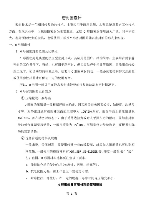
密封圈设计密封技术是一门相对较复杂的技术,主要应用于液压系统,水泵系统及其它工业技术方面。
在玩具业中,以橡胶圈密封为主要形式,尤以O形圈密封使用最为广泛,对体积较大,密封面积较大的玩具,也常使用U形及V形密封圈并辅以密封油的形式来实现。
一、O形圈密封1.O形圈密封的范围及优缺点O形圈密封是典型的挤压型密封形式,其应用范围广,结构简单,主要用在要求静密封的工作条件下。
当然,也可用于动密封,但因容易产生扭曲等原因,只能用在较轻载工况下,如活塞型的往复运动,如要用O形圈密封的话,一般必须要控制好其压缩量或使用弹性挡圈才可保证一定的使用寿命。
所以,O形圈一般只用在静态密封或轻载的往复运动动态密封情况下。
2.O形密封圈的设计要点①压缩量设计要得当O形圈的压缩量一般根据经验来确定,因其所受影响因素较多,如硬度,沟槽尺寸等,对静密封通常在圆柱表面的压缩率为10%~20%左右,而在平面上的压缩量取15%~25%,如在动密封状态下,由于受马达扭力或对人手操作力的限制,需加密封润滑油或合理调整压缩量,一般压缩量为6%~10%。
压缩量仅为经验数据,要根据实际功能要求调整。
②选择合适的材料及硬度一般来说,受压越高,要使用较硬一些的橡胶圈,或者加大压缩量也可达到相同效果,一般使用的橡胶材料有NBR、SBR、SI-RUBBER等,硬度一般在40°~80°左右范围,O形圈材料选择要注意以下要求:a.能抵抗介质的侵蚀作用(如腐蚀、溶胀、溶解等)。
b.抗老化能力强,在工作温度下要稳定可靠。
c.耐磨性好,弹性好,在一定的硬度,寿命时间内压缩变形小。
O形密封圈常用材料的使用范围③沟槽的设计常见的沟槽有矩形、三角形、半圆形、燕尾形、以矩形使用较多。
矩形槽适用于静密封和各种动密封场合,如压力来自于内径方向,则沟槽外径尺寸须与O形圈外径相等,如压力来自外径方向;则沟槽内径尺寸要与O形圈内径相等,而一般密封圈与沟槽的间隙在0.20mm以下。
o型密封圈密封结构设计

o型密封圈密封结构设计
O型密封圈是一种常用的密封结构,可以用于防止液体或气体泄漏。
其设计需要考虑以下几个关键因素:
1. 材料选择:O型密封圈一般由橡胶或硅胶等弹性材料制成,材料选择应根据具体的工作环境和介质特性来确定,确保密封圈具有良好的耐油、耐溶剂和耐高温性能。
2. 截面形状:O型密封圈的截面形状是圆环状,内径和外径之间有一定的厚度。
一般情况下,内径应与密封件的外径相匹配,确保密封圈能够紧密贴合并形成有效的密封效果。
3. 安装方式:O型密封圈可以通过压入、拉伸或固定等方式安装。
安装时应确保密封圈周边无损伤,并保证其正确位置和夹持力,以确保密封圈能够有效工作。
4. 表面处理:在设计过程中,还应考虑到密封圈与密封件接触表面的处理,如采用抛光、涂覆润滑剂等方式,以减小摩擦阻力、延长使用寿命和提高密封性能。
5. 密封压力:密封圈的设计应考虑工作环境下的压力,通过选择适当的截面形状和材料,确保密封圈在工作压力下能够保持良好的弹性和密封性能。
综上所述,O型密封圈的设计需要综合考虑材料选择、截面形状、安装方式、表面处理和密封压力等因素,以确保其具有优良的密封性能。
密封圈设计标准
密封圈设计标准
密封圈设计标准是指用于密封圈设计的一系列要求和规范。
以下是一些常见的密封圈设计标准:
1. 尺寸和公差:密封圈的尺寸和公差应符合相关的国际、国家或行业标准,如ISO、ASME、JIS等。
2. 材料选择:密封圈的材料应根据具体应用场景的要求进行选择,例如耐温度、耐化学腐蚀性能等。
3. 密封性能:密封圈的密封性能应满足设计要求,包括静密封性和动密封性。
4. 压缩率:密封圈的压缩率是指在装配时,密封圈被压缩的程度。
压缩率应根据具体的设备和应用要求进行选择。
5. 安装和拆卸:密封圈的安装和拆卸应方便快捷,并要求不会对密封圈和设备造成损坏。
6. 使用寿命:密封圈的设计应考虑到其使用寿命的要求,包括耐磨损性能和使用环境的影响。
7. 标志和标识:密封圈上应标明相关的标志和标识,以便于识别和追溯。
这些标准旨在确保密封圈在各种应用中具有合适的性能和可靠的密封效果。
具体应根据实际需要选择和应用相应的标准。
(完整版)O型圈密封圈的选用分析

O 形密封圈的选用一、概述 特点:O 形密封圈由于它制造费用低及使用方便,因而被广泛应用在各种动、静密封场合。
标准:大部分国家对O 形密封圈都制定系列产品标准,其中美国标准(AS 568)、日本标准(JIS B 2401)、国际标准(ISO 3601/1)较为通用。
O型圈标准一览表表1标准 O 型圈截面直径W美国标准 AS 568 英国标准 BS 15161.782.623.53 5.33 7.00日本标准 JIS B 2401 1.9 2.4 3.1 3.5 5.78.4国际标准 ISO 3601/1 德国标准 DIN3771/1 中国标准 GB 3452.11.82.653.55 5.307.00优先的米制尺寸1.0 1.52.0 2.53.03.54.0 4.55.0 5.56.07.08.0 10.012.0美国标准AS 568(900系列)1.02 1.42 1.631.83 1.982.08 2.21 2.462.953.00密封机理:O形密封圈是一种自动双向作用密封元件。
安装时其径向和轴向方面的预压缩赋与O形密封圈自身的初始密封能力。
它随系统压力的提高而增大。
性能参数:静态密封动态密封工作压力无挡圈时,最高可达20MPa;有挡圈时,最高可达40MPa;用特殊挡圈时,最高可达200MPa。
无挡圈时,最高可达5MPa;有挡圈时,较高压力。
运动速最大往复速度可达0.5m/s,最大旋转速度可达2.0m/s。
度一般场合:-30℃~+110℃;特殊橡胶:-60℃~+250℃;旋温度转场合:-30℃~+80℃介质见《橡胶密封件原料特性表》。
二、O形密封圈选择应考虑的因素1、工作介质和工作条件在具体选取O形圈材料时,首先要考虑与工作介质的相容性。
还须综合考虑其密封处的压力、温度、连续工作时间、运行周期等工作条件。
若用在旋转场合,须考虑由于摩擦热引起的温升。
不同的密封件材料,其物理性能和化学性能都不一样,见《橡胶密封件原料特性表》。
密封圈压缩量参考设计

密封圈压缩量参考设计密封圈是一种常用于阻止液体或气体泄漏的装置。
密封圈的效果取决于其压缩量(即密封圈被压缩的厚度)。
本文将介绍如何进行密封圈压缩量的参考设计,以确保密封圈的正常工作。
首先,密封圈的压缩量应根据具体应用环境来确定。
不同的应用场景存在不同的设计要求,例如压力、温度和介质等。
一般来说,密封圈的压缩量应足够大以确保有效的密封,但也不能过大以防止密封圈受到损坏或过度拉伸。
在确定密封圈的适当压缩量之后,可以使用以下步骤进行设计:1.确定密封圈的材料:不同的材料具有不同的弹性和耐用性。
选择适合特定应用场景的材料是成功设计的关键。
常见的密封圈材料包括橡胶、聚氨酯和聚四氟乙烯等。
2.测量密封圈的尺寸:测量密封圈的外径、内径和厚度等尺寸参数。
这些参数将直接影响到密封圈的压缩量。
3.计算压缩量:根据所需的压缩量和密封圈的尺寸参数,计算出密封圈需要被压缩的厚度。
压缩量可以通过下式计算得出:压缩量=密封圈厚度-游离高度。
4.选择适当的密封圈尺寸:根据压缩量计算结果,选择最接近的标准尺寸密封圈。
一般来说,可以选择比所需压缩量稍大的标准尺寸,然后通过压缩或拉伸的方式调整密封圈。
5.进行实验验证:设计好的密封圈需要进行实验验证,以确保其在实际使用中的密封性能符合要求。
实验可以通过压缩密封圈并测试其泄露量或压缩力等参数来进行。
需要注意的是,密封圈的压缩量设计需要综合考虑材料的弹性和可变性等因素。
不同材料在不同环境中的性能可能存在差异,因此可能需要针对不同应用场景进行适当调整。
总之,密封圈的压缩量参考设计需要根据具体应用环境来确定。
通过选择合适的材料、测量尺寸、计算压缩量、选择合适尺寸并进行实验验证,可以确保密封圈具有良好的密封性能。
密封圈压缩量参考设计
以上二图中的初始压缩变形量是根据 ISO3601-2 标准,考虑了负载与截面直径的 关系后制成的。
由于初始变化的程度不同,以及密封材料的硬度不同,O 型圈的压缩压力的大小也 有所不同。
图 1-7 显示了 O 型圈圆周每厘米长度上所承受的压缩力的大小。该图可用于估计 静密封应用时 O 型圈的总的压缩力的大小。拉伸与压缩是 O 型圈在沟槽中安装的两种形态。 在径向密封的结构配置中,O 型圈装在内沟槽中(作为“外圆密封”),O 型圈必须受到拉 伸,且其内径拉伸后大于沟槽的外径。在安装后的状态,O 型圈的最大伸长量应该为 3%(内 径>50mm)或 5%(内径<50mm).
0.8-1.2
表 1-6 静密封沟槽尺寸-径向压缩:
d2
t
b+0.20
1.50
1.10
1.90
1.80
1.40
2.40
2.00
1.50
2.60
2.50
2.00
3.20
2.65
2.20
3.60
3.00
2.30
3.90
3.55
2.90
4.80
4.00
3.25
5.20
5.00
4.10
6.50
5.30
4.50
2)挤出间隙 最大允许挤出间隙 gmax 和系统压力、O 形圈截面直径以及和材料的硬度有关。通常, 工作压力越高,最大允许挤出间隙 gmax 取值越小。如果间隙 g 超过允许范围,就会导致 O 形圈被挤出损坏。 最大允许挤出间隙 gmax 压力 MPa O 形圈截面直径 W 1.78 2.62 3.53 5.33 7.00 邵氏硬度 A70 ≤3.50 0.08 0.09 0.10 0.13 0.15 ≤7.00 0.05 0.07 0.08 0.09 0.10 ≤10.50 0.03 0.04 0.05 0.07 0.08 邵氏硬度 A80 ≤3.50 0.10 0.13 0.15 0.18 0.20 ≤7.00 0.08 0.09 0.10 0.13 0.15 ≤10.50 0.05 0.07 0.08 0.09 0.10 ≤14.00 0.03 0.04 0.05 0.07 0.08 ≤17.50 0.02 0.02 0.03 0.03 0.04 邵氏硬度 A90 ≤3.50 0.13 0.15 0.20 0.23 0.25 ≤7.00 0.10 0.13 0.15 0.18 0.20 ≤10.50 0.07 0.09 0.10 0.13 0.15 ≤14.00 0.05 0.07 0.08 0.09 0.10 ≤17.50 0.04 0.05 0.07 0.08 0.09 ≤21.00 0.03 0.04 0.05 0.07 0.08 ≤35.00 0.02 0.03 0.03 0.04 0.04 注:1、当压力超过 5MPa 时,建议使用挡圈; 2、对静密封应用场合,推荐配合为 H7/g6。 3)压缩永久变形 评定 O 形圈密封性能的另一指标,即该材料的压缩永久变形。在压力作用下,作为弹性 元件的 O 形圈,产生弹性变形,随着压力增大,会出现永久的塑性变形。压缩永久变形 d 可由下式确定:
O形密封圈设计详解(含中美日等国家标准)
一、O形密封圈的密封原理O形密封圈简称O形圈,是一种截面为圆形的橡胶圈。
O形密封圈是液压、气动系统中使用最广泛的一种密封件。
O形圈有良好的密封性,既可用于静密封,也可用于往复运动密封中;不仅可单独使用,而且是许多组合式密封装置中的基本组成部分。
它的适用范围很宽,如果材料选择得当,可以满足各种运动条件的要求,工作压力可从1.333×10⁵Pa的真空到400MPa高压;温度范围可从-60℃到200℃。
与其它密封型式相比,O形密封圈具有以下特点:1)结构尺寸小,装拆方便。
2)静、动密封均可使用,用作静密封时几乎没有泄漏。
3)使用单件O形密封圈,有双向密封作用。
4)动摩擦阻力较小。
5)价格低廉。
O形密封圈是一种挤压型密封,挤压型密封的基本工作原理是依靠密封件发生弹性变形,在密封接触面上造成接触压力,接触压力大于被密封介质的内压,则不发生泄漏,反之则发生泄漏。
在用于静密封和动密封时,密封接触面接触压力产生原因和计算方法不尽相同,需分别说明。
1、用于静密封时的密封原理在静密封中以O形圈应用最为广泛。
如果设计、使用正确,O形密封圈在静密封中可以实现无泄漏的绝对密封。
O形密封圈装入密封槽后,其截面承受接触压缩应力而产生弹性变形。
对接触面产生一定的初始接触压力Po。
即使没有介质压力或者压力很小,O形密封圈靠自身的弹性力作用而也能实现密封;当容腔内充入有压力的介质后,在介质压力的作用下,O形密封圈发生位移,移向低压侧,同时其弹性变形进一步加大,填充和封闭间隙δ。
此时,坐用于密封副偶合面的接触压力上升为Pm:Pm=Po+Pp式中Pp——经O形圈传给接触面的接触压力(0.1MPa)Pp=K·PK——压力传递系数,对于橡胶制O形密封圈K=1;P——被密封液体的压力(0.1MPa)。
从而大大增加了密封效果。
由于一般K≥1,所以Pm>P。
由此可见,只要O形密封圈存在初始压力,就能实现无泄漏的绝对密封。
这种靠介质本身压力来改变O形密封圈接触状态,使之实现密封的性质,称为自封作用。
真空密封设计
PAGE 3 OF 8VACUUM SEALS DESIGN CRITERIAFigure 2. Two O-rings are used on the 15 foot diameter chamber holding a relatively crude vacuum andsubject the inner O-ring to only a smalldifferential between the high vacuumsystem on its inner face and the partialvacuum on its outer face. As a result ofthis double pumped system, the leakageper O-ring can be greatly reduced.Vapor Pressure . The O-ring must have avery low vapor pressure at the servicetemperature. It must not have anycomponents which will vaporize at thepressures to which the joint will besubject. Resilient organic material such asViton A is most commonly used to®produce and hold vacuum as low as 10-9Torr .Temperature . The vapor pressure ofmost or all organic materials isproportional to temperature. It istherefore very important that O-ring'stemperature be limited.The best of thematerials must be held below 250F, and o for minimum outgassing an even lower temperature is recommended. Fortemperatures held below 65F, it iso possible to use carefully constructed O-ring joints at pressures as low as 10 Torr. Excessive heat,-9over time, degrades O-ring materials physically, and/or chemically, which may render them non-functional as seals. The O-ring temperature must be reduced to values between zero and -10Fo during ultra vacuum operation.Surface . It is important that the groove surfaces be so ground and polished that no residual tool marks or scratches occur at right angles to the length of the groove. Even minute scratches can produce a leak, which is difficult to locate and repair. The mating flanges, which are flat and serve to compress the O-ring must have, at the point where the O-ring contacts them, an equally good finish. The surface finish in the O-ring groove and on the flat mating flange must be at least 32micro inch and preferably 16 micro inch.PAGE 4 OF 8VACUUM SEALS DESIGN CRITERIA Permeability. In vacuum applications, high material resistance to gas permeation is directly equated with low vacuum leakage of the O-ring. Butyl and Fluorocarbon excel as the most impermeable performers. Increased O-ring compression reduces permeability by increasing the length of the path the gas has to travel (width of ring) and decreasing the area available to the entry of the gas (groove depth). Increased compression also tends to force the rubber into any small irregularities in the mating metal surface, and thus prevents leakage around the seal.Vacuum Weight Loss. It is particularly important in many space and other vacuum applications that optical surfaces and electrical contact surfaces remain clean to serve their intended purpose. Some rubber compounds contain small quantities of oil or other ingredients that become volatile under high vacuum conditions and deposit as a thin film on all the surrounding surfaces. Table 1 indicates the weight loss of several compounds due to vacuum exposure. Where sensitive surfaces are involved, the higher weight loss compounds should be avoided. In the low weight compounds, the small amount of volatile material that is indicated is primarily water vapor which is not likely to deposit on nearby warm surfaces.Table 1. Weight Loss of Compounds in VacuumTest Samples: Approximately 0.075 thick Time: 336 hours (two weeks)-6Vacuum Level : Approximately 1 x 10 torr Room TemperatureCompoun Polymer Percent Compound Polymer Percentd Number Weight Number Weight LossLossB612-70Butyl0.18N674-70Nitrile 1.06C873-70Neoprene0.13P648-90Polyurethane 1.29E515-80Ethylene Propylene0.39S455-70Silicone0.03E529-60Ethylene Propylene0.92S604-70Silicone0.31E692-75Ethylene Propylene0.76V747-75Fluorocarbon0.09L449-65Fluorosilicone0.28V884-75Fluorocarbon0.07L677-70Fluorosilicone0.25V894-90Fluorocarbon0.07N406-60Nitrile 3.45Vacuum Seal Considerations. The rate of flow of gases from the pressure side to the vacuum side of a vacuum seal depends to a great extent on how the seal is designed. As mentioned earlier in this document, increasing the compression reduces the leak rate. Lubricating the O-rings with a high vacuum grease also reduces the leak rate significantly. The vacuum grease aids the seal by filling microscopic pits and grooves produced by small irregularities in the mating metal surface. The O-ring should first be cleaned to remove all dirt and foreign material utilizing a small amountPAGE 5 OF 8VACUUM SEALS DESIGN CRITERIAof Alcohol on a cloth as a cleaning agent, and should be given a very thin coat of vacuum grease (i. e., Apiezon grease) applied by drawing it through fingers slightly coated with vacuum grease. It should be noted that vacuum grease should not be depended upon to provide any sort of vacuum seal.Vacuum Leak Approximation. The leak rate of a gas through an O-ring seal may be roughly approximated when the permeability of the gas through a particular material is known for the temperature at which the seal must function. The following formula is useful for this approximation:L . 0.7 F D P Q (1-S)2L = Approximate leak rate of the seal, std. cc/sec.F = Permeability rate of the gas through the elastomer at the2anticipatedtemperature, std. cc cm/cm sec bar. (example: Butyl'so-82permeability at 77F with Acetylene is 1.26 x 10 std. cc cm/cm sec bar) D =Inside diameter of the O-ring, inches.P =Pressure differential across the seal, lb/in.2Q =Factor depending on the percent compression and whether the O-ring islubricated or dry (from figure 3 below)S =Percent compression on the O-ring cross section expressed as a decimal(i.e. for 20% compression, S = 0.20)Note: This formula is a rough order of magnitude approximation and is based on thefollowing assumptions:1) The cross section of a compressed O-ring is rectangular.2) The cross section area of a compressed O-ring is the same as its area in the freecondition.3) The permeability rate of a gas through an O-ring is proportional to the pressuredifferential across the seal.PAGE 6 OF 8VACUUM SEALS DESIGN CRITERIAA variation of plus or minus 50% from the predicted values should be anticipated to allow for limitations in theaccuracy of test equipment and available standards, and for variations between samples.Figure 3. Effect of Compression and Lubricant on O-ring Leak RateStatic Seal Cross Section Calculation. To calculate correct cross section dimensions for static seals, list the gland depth and multiply by the minimum and maximum compression requirements (listed in Table A, Section 3 of Reference 5). For Inside Diameter (I.D., or hole diameter) calculation, list the diameter of the part the O-ring will be stretched over during installation, and reduce this figure by 1 to 5% to undersize the O-ring's I.D, allowing for stretch.Vacuum Feedthroughs. Many types of vacuum feedthroughs are available from suppliers as-11Varian Vacuum Products (Reference 6). They are designed for pressure as low as 10 Torr and provide leak-free performance in high and ultrahigh vacuum systems. With ceramic-to-metal seal construction, applications for these feedthroughs include: Instrument and Thermocouple Leads, RF Power Input, Coaxial Input, Mask and Substrate Handling, Target Movement, Liquid Cooling, High Voltage Conduction and High Current Conduction.As an example for using one type of feedthrough, electrical circuits carried into and out of ultrahigh vacuum systems must be of ceramic-to-metal seal construction. A tight bond is made between a ceramic and a kovar transition sleeve which is then welded into the stainless steel of the vacuum vessels. The actual electrical feedthroughs come through the center of the ceramicPAGE 7 OF 8VACUUM SEALS DESIGN CRITERIAinsulator and are bonded to it by special bonding techniques to achieve gas tightness. It is important that electrical leads inside ultrahigh vacuum systems must be insulated by means of non-outgassing materials. These leads should be limited to ceramic beads since all of the elastomeric type insulating materials outgas a considerable amount in vacuum systems.Rotating Seals. O-rings are used as seals for rotating shafts, with the turning shaft protruding through the internal diameter of the O-ring. The inside surface of the O-ring is continuously exposed to friction generated heat from the rotating shaft. The most important factors to consider when designing rotating seal glands are frictional heat buildup, O-ring stretch, compression, application temperature limits, and shaft glandular machining.O-rings should be comprised of compounds featuring maximum heat resistance and minimum friction generating properties. To help minimize O-ring heat buildup, the following mechanical design safeguards should be considered where applicable:1) Reduce compression to 0.002 inch to minimize friction.2) Select the O-ring with the smallest possible cross section.3) Select an O-ring comprised of a hard, self-lubricating compound (such as graphite).o o4) Avoid applications requiring lower than -40F, or higher than +250F operatingtemperatures.5) Locate the gland as close as possible to the lubricating fluid and as far away as possiblefrom the shaft support bearings.6) Assure that relative motion occurs only between the O-ring internal diameter and therotating shaft, not between the O-ring and the gland. This can be accomplished byminimizing eccentric shaft rotation (machining shafts concentric to within 0.0005 inchTIR); by finishing shaft surfaces to 16 micro inch (for smooth, non-abrasive running); and machining gland surfaces to a rougher 32 micro inch (to discourage O-ring movementwithin the gland).Technical Rationale:Vacuum chambers (ranging from 6 to 50 feet in diameter) have been utilized at LeRC for over 30 years to simulate space conditions. The reliable, reusable, long lasting, and round configuration vacuum seals demonstrate the success of using rubber O-rings to vacuum seal these small and large chambers. Environmental testing, experiments, and pre-flight tests have been fruitfully conducted in these chambers in space simulated environment. These practices were gained from LeRC's experience with vacuum seals and sources listed in the references.PAGE 8 OF 8VACUUM SEALS DESIGN CRITERIAImpact of Nonpractice:Incompatible O-ring elastomer and environmental elements, incorrect O-ring size, improper gland design (including rough surface finish), and inadequate O-ring lubrication may result in O-ring failure, joint leakage and ineffective vacuum seals. Leakage in vacuum seals can be detrimental to space crew, vehicles and equipment.Related Practices:"Static Cryogenic Seals for Launch Vehicle Applications" PD-ED-1208.References:1.Robert C. Finke, Arthur D. Holmes, and Thomas A. Keller, "Space Environment Facility for ElectricPropulsion Systems Research", NASA TN D-2774, Lewis Research Center, Cleveland, Ohio, May 1965.2.The Boeing Company, "Practical Vacuum Systems Design", Seattle, Washington, 1962.3.The Boeing Company, "Ultra High Vacuum Theory and Design", Seattle, Washington, 1963.4.Parker Seals, "Parker O-Ring Handbook", ORD 5700, Parker Seal Group, O-Ring Division, Lexington, KY,1991.5.Apple Rubber Products, "Seal Design Catalog", Apple Rubber Products Inc., Lancaster, NY, 1989.6.Varian Vacuum Products, "Varian Vacuum Products 1991/1992 Catalog", Lexington, Massachusetts, 1991.7.Donald J. Santeler, Donald W. Jones, David H. Holkeboer, and Frank Pagano, "Vacuum Technology andSpace Simulation", NASA SP-105, Washington, D.C., 1966.。
密封圈选型指南范文
密封圈选型指南范文密封圈(Sealing Ring)是一种用于封闭机械设备中泄漏的环状零件,通过填塞间隙来防止液体或气体的泄漏。
根据不同的应用和需求,选择适当的密封圈是至关重要的。
以下是一个密封圈选型指南,帮助您做出正确的选择。
首先,了解不同类型的密封圈的特点和应用是很重要的。
常见的密封圈类型包括橡胶O型圈、V型圈、油封、填料密封、金属弹簧密封等。
根据不同的工作环境和介质要求,选择适合的密封材料,如橡胶密封圈适用于较低压力和温度下的密封,可根据需要选择硅橡胶、丁腈橡胶、氟橡胶、氯丁橡胶等。
其次,了解设备的工作条件非常重要。
考虑到温度、压力、速度和介质等因素,选择适合的密封圈材料。
例如,高温环境下,可选择聚四氟乙烯(PTFE)密封圈,而在高压环境下,聚亚氏腈密封圈可能更适合。
了解设备的细节,如活塞杆、轴承孔和零件精度等,有助于选择合适的密封圈尺寸和形状。
此外,也要考虑到密封圈的硬度和弹性。
硬度较高的密封圈适合于在高压和高速度下工作,而较软的密封圈适用于填塞较大的间隙。
了解应用的挤压和复原要求,可以选择合适的密封圈硬度,如硫化硅密封圈具有良好的抗挤压性能。
此外,注意到密封圈耐磨的特性。
在一些机械设备中,由于摩擦和振动等因素,密封圈容易磨损,影响其密封性能。
选择耐磨性好的密封材料可以减少磨损,延长密封圈的使用寿命,如聚酯密封圈能在一定程度上提高耐磨性。
最后,考虑设备的维护和更换成本也是选择密封圈时需要考虑的因素。
一些密封圈需要经常更换,而一些密封圈的使用寿命较长,需要较少的维护。
根据预算和工作要求,选择经济实用的密封圈材料和构造。