微型步进电机驱动器RS232串口型UIM241使用手册
MS3540MI 步进电机驱动器说明书

MS3540MI步进电机驱动器使用手册MS3540MI步进电机驱动器使用手册1. 产品简介1.1 概述MS3540MI为智能型双极细分型步进电机驱动器。
该驱动器集成了运动控制功能,可使用Mis可编程软件通过RS232接口下载程序;也可使用SCL语言通过PC、PLC或MCU实现对驱动器及电机的实时控制。
驱动器上的可编程的输入、输出接口用于和外部开关、传感器等其它元件进行同步,在简单的运动控制中可将该驱动器作为控制器使用,减少了系统元件的数量,降低了系统集成的复杂度和成本。
1.2 特点•12-42V 直流电压供电•0.2-3.5A 相电流(峰值),通过软件配置•自动减流功能,通过软件配置•13 种细分选择,通过软件配置••8 个可编程的光电隔离输入信号端口3 个可编程的光电隔离输出信号端口MS3540MI步进电机驱动器使用手册电机•驱动器•齿轮箱•开关电源- 1 - •双极性PWM 恒流斩波控制,开关频率20-30kHz•人机交互界面(MSMMI)配件可选•利用Mis 编程软件方便地对驱动器进行编程,使其独立实现运动控制功能•利用SCL 驱动器编程语言,可以实现驱动器与PC、PLC 或MCU 的连接,以对驱动器进行实时控制操作•通过Mis 网络集线器可以使驱动器与其它的Mis 系列驱动器进行网络互连,实现- 2 -MS3540MI步进电机驱动器使用手册一台主机同时控制多台驱动器的功能输入输出2. 功能框图MS3540MI步进电机驱动器使用手册5-24V 信号,光电隔离输入。
2200ohms 内部电阻。
(可采用下拉(NPN)或上拉(PNP)控制信号电路)光电隔离。
光敏三极管C、E 间最大电压24V,最大输出电流100 mA。
细分13 种细分选择可通过软件配置。
如采用 1.8˚电机,则每圈转动步数:2000, 5000, 10000, 12800, 18000, 20000, 21600,25000,25400, 25600, 36000, 50000, 50800.运动刷新频率12800Hz.物理特性装在黑色阳极氧化的铝散热底盘上。
UT-201 RS-232转RS-485接口转换器使用说明书
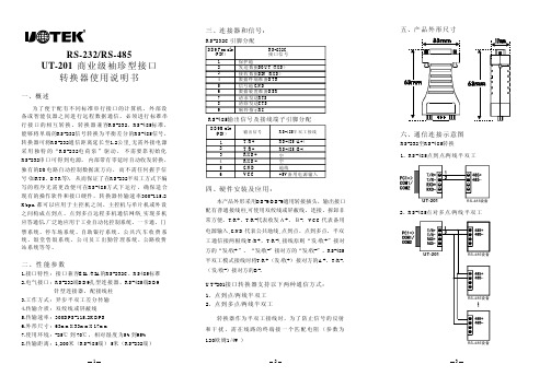
1RS-232/RS-485UT-201商业级袖珍型接口转换器使用说明书RS-232RS-485RS-232RS-485RS-232 1.2,RS-232RS-232I/O (RTS DTR )RS-232RS-485300-115.2Kbps.,.1.EIA/TIA RS-232C RS4852.RS-232DB9RS-485DB93.4.5.300BPS-115.2KBPS6.63mmX33mmX17mm7.-25705%95%8.1,200RS-4855RS-232为了便于配有不同标准串行接口的计算机、外部设备或智能仪器之间进行远程数据通信,必须进行标准串行接口的相互转换。
转换器兼容、标准,能够将单端的信号转换为平衡差分的信号,转换器可将通信距离延长至公里无需外接电源采用独特的“电荷泵”驱动,不需要靠初始化串口可得到电源,内部带有零延时自动收发转换,独有的电路自动控制数据流方向,而不需任何握手信号如、等,从而保证了在半双工方式下编写的程序无需更改便可在方式下运行,确保适合现有的操作软件和接口硬件,转换器传输速率都可以应用于主控机之间、主控机与单片机或外设之间构成点到点、点到多点远程多机通信网络实现多机应答通信广泛地应用于工业自动化控制系统、一卡通、门禁系统、停车场系统、自助银行系统、公共汽车收费系统、饭堂售饭系统、公司员工出勤管理系统、公路收费站系统等等。
接口特性:接口兼容的、标准电气接口:端孔型连接器,端针型连接器,配接线柱工作方式:异步半双工差分传输传输介质:双绞线或屏蔽线传输速率:外形尺寸:使用环境:℃到℃,相对湿度为到传输距离:米(端)米(端)二、性能参数一、概述五、产品外形尺寸六、通信连接示意图RS-232RS-485至转换2RS-485/、点对多点两线半双工UT-201RS-485设备RS-485设备RS-485设备1RS-485/、点到点两线半双工UT-201RS-485设备23SIN (RXD)DTR GND DSR RTS CTS RI 保护地接收数据数据终端准备信号地数据装置准备请求发送清除发送响铃指示发送数据SOUT (TXD)DB9Female (PIN)123456789RS-232C 接口信号1/2/、点到点两线半双工、点到多点两线半双工UT-201接口转换器支持以下两种通信方式:DB9Male (PIN)123456T/R+T/R-RXD+RXD-GND VCC 输出信号RS-485半双工接线RS-485(A+)RS-485(B-)+5V 空空地线备用电源输入DB-9/DB-9,T/R+T/R-+-VCC ,GND ,(T/R+T/R-),/+/+/-/-RS-485T/R+/+A+T/R-/-B-本产品外形采用通用转接插头,输出接口配有普通接线柱可使用双绞线或屏蔽线,连接、拆卸非常方便。
研控科技 YSS-R系列步进电机驱动器用户手册 V1.0说明书

深圳市研控自动化科技有限公司目录前言 (1)1概述 (2)1.1产品介绍 (2)1.2特性 (2)1.3应用领域 (2)1.4产品命名规则 (3)2性能指标 (4)2.1电气特性 (4)2.2使用环境 (4)3安装 (5)3.1安装尺寸 (5)3.2安装方法 (5)4 驱动器端口与接线 (6)4.1接线示意图 (6)4.2接口定义 (7)4.2.1状态指示灯 (7)4.2.2通讯端口 (7)4.2.3输入/输出端口 (7)4.2.4电源端口 (8)4.2.5拨码开关 (8)4.3输入/输出端口操作 (8)4.4拨码开关设定 (9)4.5通讯端口 (10)5 电机规格及接线 (11)5.1技术规格 (11)5.2电机接线图 (11)6 MODBUS通讯协议 (12)6.1 MODBUS寄存器地址定义 (12)6.2 MODBUS常用功能码 (19)6.2.1读保持寄存器命令03 (19)6.2.2写单个寄存器命令06 (20)6.2.3写多个寄存器命令16 (20)6.2.4通讯错误码 (21)6.2.5应用示例 (22)7运动控制功能介绍 (24)7.1位置模式 (24)7.2速度模式 (25)7.3多段位置模式 (25)7.3.1 位置段参数介绍 (25)7.3.2 多段位控制方式 (26)7.4多段速度模式 (27)7.4.1 速度段参数介绍 (27)7.4.2 多段速度控制方式 (27)7.5回原点功能 (28)7.6 运动控制命令 (29)7.6.1 启动命令(0x0027) (29)7.6.2 停止命令(0x0028) (29)7.6.3 回原点命令(0x0030) (30)8报警排除 (31)9版本修订历史 (32)10保修及售后服务 (33)10.1保修 (33)10.2售后服务 (33)前言感谢您使用本公司步进电机驱动器。
在使用本产品前,请务必仔细阅读本手册,了解必要的安全信息、注意事项以及操作方法等。
步进电机驱动器说明书

TB6600升级版两相步进驱动器使用说明书[使用前请仔细阅读本手册,以免损坏驱动器]目录一、产品简介 (3)概述 (3)特点 (3)二、接口和接线介绍 (3)信号输入端 (3)电机绕组连接 (3)电源电压连接 (4)状态指示 (4)接线方式 (4)接线要求 (5)三、电流、细分拨码开关设定 (5)细分设定 (5)工作(动态)电流设定 (6)四、机械和环境指标 (6)使用环境及参数 (6)机械安装图 (7)五、电机适配 (7)电机适配 (7)电机接线 (8)供电电压和输出电流的选择 (8)五、常见问题 (9)应用中常见问题和处理方法 (9)六、保修条款 (10)◆概述TB6600升级版驱动器是一款专业的两相混合式步进电机驱动器,可适配国内外各种品牌,电流在4.0A及以下,外径39,42,57mm的四线,六线,八线两相混合式步进电机。
适合各种小中型自动化设备和仪器,例如:雕刻机、打标机、切割机、激光照排、绘图仪、数控机床、拿放装置等。
在用户期望低成本、大电流运行的设备中效果特性。
◆特点※信号输入:单端,脉冲/方向※细分可选:1/2/4/8/16/32细分※输出电流:0.5A-4.0A※输入电压:9-42VDC※静止时电流自动减半※可驱动4,6,8线两相、四相步进电机※光耦隔离信号输入,抗干扰能力强※具有过热、过流、欠压锁定、输入电压防反接保护等功能※体积小巧,方便安装※外部信号3.3-24V通用,无需串联电阻◆信号输入端PUL+ PUL-脉冲输入信号。
默认脉冲上升沿有效。
为了可靠响应脉冲信号,脉冲宽度应大于1.2us。
DIR+ DIR-方向输入信号,高/低电平信号,为保证电机可靠换向,方向信号应先于脉冲信号至少5us建立。
电机的初始运行方向与电机绕组接线有关,互换任一相绕组(如A+、A-交换)可以改变电机初始运行方向。
ENA+ ENA-使能输入信号(脱机信号),用于使能或禁止驱动器输出。
使能时,驱动器将切断电机各相的电流使电机处于自由状态,不响应步进脉冲。
步进电机控制说明书

1题目:2 电路原理图的设计2.1步进电机控制电路原理图硬件总体电路原理图如下图2.1所示,图2.1 2.2 LCD显示模块LCD1602与51单片机的接口原理图如下图2.2,2.3L297/298电机驱动模块L297、L298与单片机的接口原理图如下图2.3,图2.3L297能产生4相控制信号,其用于分辨单片机传送给它的信号是低电平还是高电平,以采取相应的措施工作。
L298是步进电机专用驱动芯片,是2相和4相步进电机的专用驱动器,驱动46V,2A 以下的步进电机,如上图2.3所示。
2.4 键盘控制模块(加速、减速、正转、反转)键盘控制模块的链接方式如图2.5所示图2.2图2.5由这4个键分别来控制电机的转动情况:加速,减速,正转,反转。
3软件系统设计3.1软件系统的流程结构3.2主程序模块#include "AT89X51.h"int delay();void inti_lcd();void show_lcd(int);void cmd_wr();void ShowState();void clock(unsigned int Delay) ;void DoSpeed(); //计算速度//正转值#define RIGHT_RUN 1//反转值#define LEFT_RUN 0sbit RS=0xA0;//P2口地址sbit RW=0xA1;sbit E=0xA2;char SpeedChar[]="SPEED(n/min):";char StateChar[]="RUN STATE:";char STATE_CW[]="CW";char STATE_CCW[]="CCW";char SPEED[3]="050";unsigned int RunSpeed=50; //速度unsigned char RunState=RIGHT_RUN; //运行状态main(){/*定时器设置*/TMOD=0x66; //定时器0,1都为计数方式;方式2;EA=1; //开中断TH0=0xff; //定时器0初值FFH;TL0=0xff;ET0=1;TR0=1;TH1=0xff; //定时器1初值FFH;TL1=0xff;ET1=1;TR1=1;IT0=1; //脉冲方式EX0=1; //开外部中断0:加速IT1=1; //脉冲方式EX1=1; //开外部中断1:减速inti_lcd();DoSpeed();ShowState();while(1){clock(RunSpeed);//延时时间P0_1=P0_1^0x01;//什么意思,用与或也行的}}//定时器0中断程序:正转void t_0(void) interrupt 1{RunState=RIGHT_RUN;P0_0=1;//控制CW CCW的P1=0x01;cmd_wr();ShowState();}//定时器1中断:反转void t_1(void) interrupt 3{RunState=LEFT_RUN;P0_0=0;P1=0x01;cmd_wr();ShowState();}//中断0:加速程序void SpeedUp() interrupt 0{if(RunSpeed>=12)RunSpeed=RunSpeed-2;DoSpeed();P1=0x01;cmd_wr();ShowState();}//中断1:减速程序void SpeedDowm() interrupt 2{if(RunSpeed<=100)RunSpeed=RunSpeed+2;DoSpeed();P1=0x01;cmd_wr();ShowState();}int delay() //判断LCD是否忙{int a;start:RS=0;RW=1;E=0;for(a=0;a<2;a++);E=1;P1=0xff;if(P1_7==0)return 0;elsegoto start;}void inti_lcd() //设置LCD方式{P1=0x38;cmd_wr();delay();P1=0x01; //清除cmd_wr();delay();P1=0x0f;cmd_wr();delay();P1=0x06;cmd_wr();delay();P1=0x0c;cmd_wr();delay();}void cmd_wr() //写控制字{RS=0;RW=0;E=0;E=1;}void show_lcd(int i) //LCD显示子程序{P1=i;RS=1;RW=0;E=0;E=1;}void ShowState() //显示状态与速度{int i=0;while(SpeedChar[i]!='\0'){delay();show_lcd(SpeedChar[i]);i++;}delay();P1=0x80 | 0x0d;cmd_wr();i=0;while(SPEED[i]!='\0'){delay();show_lcd(SPEED[i]);i++;}delay();P1=0xC0;cmd_wr();i=0;while(StateChar[i]!='\0'){delay();show_lcd(StateChar[i]);i++;}delay();P1=0xC0 | 0x0A;cmd_wr();i=0;if(RunState==RIGHT_RUN)while(STATE_CW[i]!='\0'){delay();show_lcd(STATE_CW[i]);i++;}elsewhile(STATE_CCW[i]!='\0'){delay();show_lcd(STATE_CCW[i]);i++;}}void clock(unsigned int Delay) //1ms延时程序{ unsigned int i;for(;Delay>0;Delay--)for(i=0;i<124;i++);}void DoSpeed(){SPEED[0]=(1000*6/RunSpeed/100)+48;SPEED[1]=1000*6/RunSpeed%100/10+48;SPEED[2]=1000*6/RunSpeed%10+48;}4仿真及调试如图4.1(1)、图4.1(2)所示5.总论图4.1(1)图4.1(2)参考文献致谢。
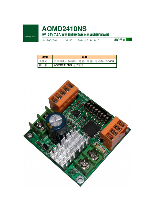
AQMD2410NS电机驱动器用户手册(V0.95)
3.1 通讯参数..........................................................................................................................30
3.2 MODBUS-RTU帧格式.....................................................................................................30
修订历史
版本 V0.90 V0.91 V0.92 V0.93 V0.94 V0.95
日期 2012/08/20 2013/03/15 2013/06/08 2013/08/08 2014/03/05 2014/11/18
AQMD2410NS
9V–24V 7.5A 高性能直流电机调速器/驱动器
原因 创建文档。 产品升级,修改限位和通讯协议部分 修改系统参数、速度预设部分寄存器描述 增加保修说明书 在各种接法中添加拨码开关的配置 修改多站点通讯的接法,增加部分寄存器的说明
Eude ?
User guide
AQMD2410NS
9V–24V 7.5A 高性能直流有刷电机调速器/驱动器
UM12082001
V0.95 Date: 2014/11/18
用户手册
类别 关键词 摘要
内容 直流电机、驱动器、调速、稳速、电位器、RS485 AQMD2410NS 用户手册
成都爱控电子科技有限公司
用户手册
2
Date:2014/11/Fra bibliotek8V0.95
成都爱控电子科技有限公司
JXCM1-TF2Z200EN CC-Link 步进电机控制器使用说明书
Instruction ManualStep Motor Controller – CC-Link(24 VDC Servo)Series JXCM1##-#The intended use of the step motor controller is to controlthe movement of an electrical actuator whilst connectedto the CC-Link protocol.These safety instructions are intended to prevent hazardous situations and/or equipment damage. These instructions indicate the level of potential hazard with the labels of “Caution,” “Warning” or “Danger.”They are all important notes for safety and must be followed in additionto International Standards (ISO/IEC) *1), and other safety regulations.IEC 60204-1: Safety of machinery - Electrical equipment of machines. (Part 1: General requirements)ISO 10218-1: Robots and robotic devices - Safety requirements for industrial robots - Part 1: Robots.•Refer to product catalogue, Operation Manual and Handling Precautions for SMC Products for additional information.• Keep this manual in a safe place for future reference.Caution Caution indicates a hazard with a low level of risk which, ifnot avoided, could result in minor or moderate injury.Warning Warning indicates a hazard with a medium level of riskwhich, if not avoided, could result in death or serious injury.Danger Danger indicates a hazard with a high level of risk which, ifnot avoided, will result in death or serious injury.Warning•Always ensure compliance with relevant safety laws and standards.•All work must be carried out in a safe manner by a qualified person in compliance with applicable national regulations.2.1 General specificationsItem SpecificationsCompatible motor Step motor (servo 24 VDC)Power supply voltage24 VDC +/-10%(motor drive control, stop, lock brake release).Current consumption 3A (Peak 5A) maximumCompatible encoderBattery-less absolute encoder (resolution: 4096 pulses / rotation)Serial communication RS485Locking Unlocking terminal (applicable to non-exitationmagnetizing lock)Cable length Actuator cable: 20 m maximum Cooling method Air-cooling type Operatingtemperature0o C to 55o C (No freezing) Storage temperature -10o C to 60o C (No freezing) Operating humidity 90% RH or less (No condensation)Insulation resistance50 MΩ (500 VDC)between the external terminals and caseWeight170 g (Direct mounting type)190 g (DIN rail mounting type)2.2 CC-Link specificationsWarningSpecial products (-X) might have specifications different from thoseshown in this section. Contact SMC for specific drawings.3 Name and function of individual parts4 Installation4.1 InstallationWarning•Do not install the product unless the safety instructions have been readand understood.•Design the installation so that the temperature surrounding thecontroller is 55o C max. Leave enough space between the controllersso that the operating temperature of the controllers remains within thespecification range.•Mount the controller vertically with 30 mm minimum space on the topand bottom of the controller as shown below.•Allow 60 mm minimum space between the front of the controller and adoor (lid) so that the connectors can be connected and disconnected.4.2 Mounting•The controller can be direct mounted (model JXCM17#) using screwsor mounted on a DIN rail (model JXCM18#).•When using DIN rail mounting, hook the controller on the DIN rail andpress the lever down to lock it.CautionIf the mounting surface for the controller is not flat or is uneven, excessivestress may be applied to the enclosure, which can cause failure. Be sureto mount on a flat surface.4.3 EnvironmentWarning•Do not use in an environment where corrosive gases, chemicals, saltwater or steam are present.•Do not use in an explosive atmosphere.•Do not expose to direct sunlight. Use a suitable protective cover.•Do not install in a location subject to vibration or impact in excess ofthe product’s specifications.•Do not mount in a location exposed to radiant heat that would result intemperatures in excess of the product’s specifications.•Avoid mounting the controller near a vibration source, such as a largeelectromagnetic contactor or circuit breaker on the same panel.•Do not use in an environment with strong magnetic fields present.4.4 WiringCaution•Do not perform wiring while the power is on.•Confirm proper insulation of wiring.•Do not route wires and cables together with power or high voltagecables.•Keep wiring as short as possible to prevent interference fromelectromagnetic noise and surge voltage.•Do not use an inrush current limited type of power supply for thecontroller.•Do not connect multiple wires to one connector terminal.Power Supply ConnectorWire the power supply cable to the power supply plug connector, theninsert it into connector PWR on the controller.•Use special screwdriver (Phoenix Contact No. SZS0.4×2.0) to open /close lever and insert the wire into the connector terminal.•Applicable wire size: 20 AWG (0.5 mm2).PinNo.Terminal Function Description1 C24V Power supply (+) Positive control power.2 M24V Motor power (+)Positive power for theactuator motor suppliedvia the controller.3 EMG Stop (+)Positive power foremergency stop signal4 0V Common power (-)Negative common power forM24V, C24V, EMG and LKRLS.5 - NC N/A6 LK RLS Unlocking (+)Positive power for lockrelease.30 mm min. (Direct mounting)50 mm min. (DIN rail mounting)30 mm minimumControllerORIGINAL INSTRUCTIONS②③④⑤⑥⑦⑧⑪①⑨Power Supply Wire specificationsPrepare the wiring according to the following specifications (to be prepared by the user).Communication ConnectorWire the CC-Link communication cable to the communication plug connector, then insert it into connector CN5 on the controller.• Use special screwdriver (Phoenix Contact No. SZS0.6×3.5) to tighten the connector terminal screws. Tightening torque = 0.5 to 0.6 N•m. • Applicable wire size: 12 to 24 AWG (0.2 to 2.5 mm 2)Straight type (LEC-CMJ-S) T-branch type (LEC-CMJ-T)Phoenix Contact No. Phoenix Contact No. MSTB2,5/5-ST-5,08 AU MSTB2,5/5-ST-5,08 AU• The CC-Link system has different terminating resistance requirements depending on the cables used.• Connect a terminating resistor to both ends of the CC-Link main line.Cable typeResistance CC-Link communication cable 110 Ω ±5% 1/2W CC-Link high performance cable130 Ω ±5% 1/2W4.5 Ground connection• Place a ground cable with crimped terminal under one of the M4 mounting screws with a shakeproof washer and tighten the screw.CautionThe M4 screw, cable with crimped terminal and shakeproof washer must be prepared by the user.The controller must be connected to Ground to reduce noise. If higher noise resistance is required, ground the 0 V (signal ground). When grounding the 0 V, avoid flowing noise from ground to 0 V.• A dedicated Ground connection must be used. Grounding should be to a D-class ground (ground resistance of 100 Ω maximum).• The cross-sectional area of the ground cable shall be 2 mm 2 minimum. • The Grounding point should be as near as possible to the controller. Keep the grounding cable as short as possible.5.1 Switch settingSet the CC-Link address and the CC-Link communication speed using the STATION NO, and B RATE rotary switch.• STATION NO. switch Switch name Set range DescriptionSTATION NO. X10 01 to 64Set upper bits of the station STATION NO. X1Set lower bits of the stationThe CC-Link address setting at the time of the factory shipment is set in “01".• B RATE (Baud Rate) switchThe CC-Link communication speed (Baud Rate) setting at the time of the factory shipment is set in “0" (156 kbps).*1) When the setting is 1 for the Occupied number of stations, the setting of Occupied number of stations will reset to 2 (default) by applying power with the B RATE switch set to 9.6 LED DisplayRefer to the table below for details of the LED status.LEDDescriptionPWROFFPower is not supplied Green LED is ON Power is suppliedGreen LED is flashingEEPROM memory writing ALMOFFNormal operationRed LED is ONController Alarm generated L ERROFFNormal operation Red LED is ON Error is generated Red LED is flashingL RUN OFFCC-Link Communication disconnectedGreen LED is ON CC-Link Communicating Green LED is flashingError is generated7 How to OrderRefer to the catalogue on the SMC website (URL: https:// ) for the How to Order information.8 Outline Dimensions (mm)Refer to the drawings / operation manual on the SMC website (URL: https:// ) for outline dimensions.9.1 General MaintenanceCaution• Not following proper maintenance procedures could cause the product to malfunction and lead to equipment damage.• Before performing maintenance, turn off the power supply. Check the voltage with a tester 5 minutes after the power supply is turned OFF. • If any electrical connections are disturbed during maintenance, ensure they are reconnected correctly and safety checks are carried out as required to ensure continued compliance with applicable national regulations.• Do not make any modification to the product.• Do not disassemble the product, unless required by installation or maintenance instructions.Caution• Maintenance should be performed according to the procedure indicated in the Operation Manual.• When equipment is serviced, first confirm that measures are in place to prevent dropping of work pieces and run-away of equipment, etc, then cut the power supply to the system. When machinery is restarted, check that operation is normal with actuators in the correct position.Warning• Perform maintenance checks periodically.• Confirm wiring and screws are not loose. Loose screws or wires may cause unexpected malfunction.• Conduct an appropriate functional inspection and test after completing maintenance. In case of any abnormalities (if the actuator does not move, etc.), stop the operation of the system. Otherwise, an unexpected malfunction may occur and it will become impossible to ensure safety. Operate an emergency stop instruction to confirm safety. • Do not put anything conductive or flammable inside of the controller. • Ensure sufficient space around the controller for maintenance.10 Limitations of Use10.1 Limited warranty and Disclaimer/Compliance Requirements Refer to Handling Precautions for SMC Products.11 Product disposalThis product shall not be disposed of as municipal waste. Check your local regulations and guidelines to dispose of this product correctly, in order to reduce the impact on human health and the environment.12 ContactsRefer to or www.smc.eu for your local distributor / importer.URL: https:// (Global) https://www.smc.eu (Europe) SMC Corporation, 4-14-1, Sotokanda, Chiyoda-ku, Tokyo 101-0021, Japan Specifications are subject to change without prior notice from the manufacturer. © 2021 SMC Corporation All Rights Reserved. Template DKP50047-F-085M5 4 3 2 154 3 2 1。
安浦鸣志集成式步进电机STM24SF手册
STM24SF 集成式步进电机用户手册目录1 产品介绍 (4)1.1 特性 (4)1.2 功能框图 (5)1.3 安全须知 (6)2 开始前的准备 (7)2.1 安装上位机软件 (7)2.2 安装集成式电机 (7)2.3 选择合适的电源 (8)2.3.1 选择电源电压 (8)2.3.2 选择电源电流 (9)3 安装及接线 (11)3.1 连接电源 (11)3.2 通信接线 (12)3.2.1 RS-232的通信接线 (12)3.2.2 RS-422/485的通信接线 (13)3.2.3 分配地址 (16)3.3 输入&输出 (17)3.3.1 连接器引脚图 (17)3.3.2 I/O1 & I/O2 数字输入 (18)3.3.3 I/O3 数字输入 (19)3.3.4 模拟量输入 (20)3.3.5 灵活输出 (I/O1, I/O2, I/O3, I/O4) (20)4 软件配置 (22)4.1 软件菜单 (22)4.1.1 文件下拉菜单 (22)4.1.2 驱动器下拉菜单 (22)4.1.3 帮助菜单 (23)4.2 驱动器型号及固件版本 (23)4.3 电机参数配置 (集成式电机) (24)4.3.1 运行电流 (24)4.3.2 加速/减速电流 (24)4.3.3 空闲电流 (24)4.3.4 空闲电流延时 (25)4.3.5 负载惯量 (25)4.3.6 电子阻尼/抗中频共振 (25)4.3.7 波形平滑 (25)4.4 控制模式及输入输出设置 (25)4.4.1 脉冲方向模式 (26)4.4.2 速度模式 (28)4.4.3 SCL 模式 (32)4.5 编码器功能 (35)4.6 上传/下载 (36)5 操作示例 (37)6 错误代码 (39)7 参考资料 (40)7.1 机械尺寸 (40)7.2 技术规格 (41)7.3 力矩曲线 (43)7.4 SCL 指令参考 (44)7.5 散热 (45)8 联系 MOONS’ (46)本用户手册所述内容仅适用于以下机型:1 产品介绍感谢您选择鸣志STM24SF集成式电机产品,STM24SF系列集成式电机是驱动与步进电机的完美结合,它融合了步进电机与驱动技术于一体,节约了安装空间、简化了繁琐的接线并节省合并设计成本,是应用步进系统方案时的首选。
步进电机驱动器数据手册
四海SH2034D步进电机驱动器
采用高频脉宽调制技术,具有噪音低、效率高
产品介绍
一、概述
SH2034D型步进电机驱动器是我厂在原有驱动电源的基础上吸收新型、高速单片机技术开发出的新颖细分驱动器。
该驱动器采用高频脉宽调制技术,具有噪音低、效率高、温升低、设置灵活、形体美观、运行特性良好等优点。
二、驱动器的使用说明
输入电源接口:采用一组交流供电,AC接AC20-40V,3A或接一组直流供电DC24-50V,3A。
警告:电压不能超出此范围,否则会造成故障,注意正负极性。
电机接口:对于二相四线电机,可直接与驱动器相连(如图二A)。
对于四相六线电机,中间两抽头悬空不接,其余四线与驱动器相连(如图二B)。
对于四相八线电机,通常有两种接法:并联接法:红长联绿短接至A+,红短联绿长接至A-,黄长联蓝短接至B+,黄短联蓝长接至B-(如图二C)。
串联接法:红长接至A+,红短联绿短悬空,绿长接至A-,黄长接至B+,黄短联蓝短悬空,蓝长接至B- (如图二D)。
注意:悬空的接头要处理好,否则会造成故障.(如图二)
警告:电机线不能接错,否则有可能会损坏本驱动器。
红长和绿长,及红短和绿短不能同时短接。
三、外形及安装尺寸
驱动器采用带散热器的外壳结构,安装时应注意驱动器的散热。
(单位:mm)。
电机驱动器说明
f
3
0
p
C
1
1
1 7 2 0 7 5 3
8
1 6
0
L298N
U
p
G
EN
B
EN
A
IN4
IN3
IN2
IN1
2
C
N 6
D 11.0592M
ISEN
B
ISEN
A
OUT4
OUT3
OUT2
OUT1
VSS
V
S
1
1
1
1
3
2
4
9
5
4
3
+5V 1
2
+5V
Download
3
4
+12V
5
6
7
8
9
ቤተ መጻሕፍቲ ባይዱ
1 0
2
1N4007
D
1N4007
P2.0
1
C
0 3
4
LM1
P1.3
P1.2
P1.1
P1.0
Vin
G
N
D Vout
LED4
LED3
LED2
LED1
220UF
LIP4
LIP3
LIP2
LIP1
C
2
+5V
LIP1 R-2
1
2 LIP2
1
2
1
2
1
2
1
1
C
2
0 4
TLP4 LIP3
TLP3
TLP2
TLP1
4
3
LIP4
4
1