UCS1909说明书-2010-12-03
三菱PLC使用说明书

→请参考FX3U系列用户手册[硬件篇] →请参考FX3UC系列用户手册[硬件篇]
2.1.1 DIN导轨安装
产品可以安装在DIN46277(宽35mm)的DIN导轨上。
1) 将 [DIN 导轨安装用沟槽的上侧 ( 右图 A)] 对准并 挂到[DIN导轨]上。
1)
2) 将产品按压在[DIN导轨]上。
- 请在产品与产品之间留出1~2mm左右的间
*2 D类接地
D类接地
*1 XD24
带屏蔽双绞线电缆
*3 DISABLE
XD 5
COMD *1
P24+
P12++ P-
带屏蔽双绞线电缆 PRESET *3
D类接地
D类接地
*2 Z相
*1 编码器的驱动电源。 请根据编码器规格,在DC24V、DC12V、DC5V中选择使用。 与FX3U-2HC连接A相、B相、Z相时,请连接与电源相匹配的端子。 此外,PRESET及DISABLE信号使用DC24V时,请与DC24V用端子(P24+,XD24)连接。
1. 产品概要
1.1 产品概要
华灿兴 H802TV 说明书

H802TV说明书更新日期:2011-10-13一、简介H802TV是通过DVI/HDMI接口传输数据的联机主控,不仅支持多显示器的扩展模式和双显示器模式,还支持复制模式。
可以脱离PC软件独立运行,所以除了连接电脑外,还可以连接DVD、iPhone等。
配套分控为H801RA。
配套软件联机为《LED演播软件》V3.67及以上版本。
目前可以控制的驱动芯片有LPD6803,LPD8806,LPD1109,TLS3001,TLS3002,TM1812,TM1809,TM1804,TM1803,DMX512,WS2801,SM16716,APA102,UCS6912, UCS1903,UCS1909,UCS1912,DM412,DM413,DM114,DM115,DM13C,DM134,DM135, DM136,74HC595,6B595,MBI5001,MBI5168,MBI5016,MBI5026,MBI5027, TB62726,TB62706,ST2221A,ST2221C,XLT5026,ZQL9712,ZQL9712HV等。
二、性能特点1、每台最大控制30万像素点,四个输出网口,每个网口最多控制7.5万点,每个网口最多连接255个分控。
2、支持DVI视频分割器,多台主控同时使用,控制几百万点的大屏。
3、支持多种分辨率1024X768、800X600、1280X768、1600X1200等。
4、支持各种屏幕刷新频率:60Hz、70Hz、72Hz、75Hz、85Hz等。
5、每个分控最大控制2048像素点,一个输出端口,其它三个端口输出一样。
6、采用免驱动USB传输控制数据,32位和64位操作系统同样使用。
三、与H801TV的主要区别1、H801TV不支持复制模式,不能脱离电脑软件;H802TV支持复制模式,可以独立运行,可联机各种DVI/HDMI输出设备。
2、H801TV八个输出网口,可控制78万点,可任意造型,分控设置更灵活;H802TV四个输出网口,可控制30万点,分控只能一个输出端口,只能控制规则屏。
UMC1000-产品更新说明
1.3.5 DOR416开关输出模块
36.0 7.5
C3-DIT316
25.0
单位:mm
② ① C3-DOR416
104.95
130.0
③
104.0 32.0
④
正面图
项目 ① ② ③ ④
侧面图
底部图
名称 电源指示灯 通讯指示灯 错误指示灯 输出指示灯
图1-12 DOR416模块
说明 指示电源状态,通电时常亮为绿色 通讯正常时为黄色闪烁 报错时为红色常亮 对应显示输入16路信号状态,满足输出时为绿色常亮
[T.OUT1] [T.OUT2]
VA VA
_ 11 ACU902模块输出信号可触发SSR固态继电器输出信
+
12
号,用户将固态继电器的直流输入部分的“+”接到
_ 13 温度输出端12,固态继电器的直流输入部分的“-”
+
接到温度输出端11,固态继电器的交流输出部分用户
14
应根据设备要求自行接线。
注:
1. 输出端的信号为12VDC信号,无需再接外部电源。
更新原因如下: 1) 增强模块的输入、输出抗干扰能力。 2) 增加PT100-2传感器类型,此传感器类型可测量至2位小数点。 3) 模块间的通讯方式改为总线通讯通讯。 4) 减少电源和模块配电。 5) 所有接线端子带有锁扣螺丝,增强端子的安全性。 6) 增强模块的扩展性。 7) 主输出、冷输出及变送输出的输出类型可在(Relay,SSR,4~20mA)间选择。 8) PID控制算法更新,增加抗超调抑制参数。 9) PID控制加热制冷双PID参数。 10)为之后推出的Chamber软件平台做硬件准备。
模块、DOR416开关输出模块)及GH5通讯电缆。
UC-5100系列嵌入式计算机商品说明书

P/N: 1802051001010 *1802051001010*UC-5100 SeriesQuick Installation GuideEdition 1.0, May 2018Technical Support Contact Information/supportMoxa Americas:Toll-free: 1-888-669-2872 Tel: 1-714-528-6777 Fax: 1-714-528-6778 Moxa China (Shanghai office): Toll-free: 800-820-5036 Tel: +86-21-5258-9955 Fax: +86-21-5258-5505 Moxa Europe:Tel: +49-89-3 70 03 99-0 Fax: +49-89-3 70 03 99-99 Moxa Asia-Pacific:Tel: +886-2-8919-1230 Fax: +886-2-8919-1231 Moxa India:Tel: +91-80-4172-9088 Fax: +91-80-4132-10452018 Moxa Inc. All rights reserved.OverviewThe UC-5100 Series embedded computers are designed for industrial automation applications. The computers feature 4 RS-232/422/485 full-signal serial ports with adjustable pull-up and pull-down resistors, dual CAN ports, dual LANs, 4 digital input channels, 4 digital output channels, a SD socket, and a mini PCIe socket for wireless module in a compact housing with convenient front-end access to all these communication interfaces.Model Names and Package ChecklistThe UC-5100 Series includes the following models:UC-5101-LX: Industrial computing platform with 4 serial ports, 2 Ethernet ports, SD socket, 4 DI, 4 DO, -10 to 60°C operating temperature rangeUC-5102-LX: Industrial computing platform with 4 serial ports, 2 Ethernet ports, SD socket, mini PCIe socket, 4 DI, 4 DO, -10 to 60°C operating temperature rangeUC-5111-LX: Industrial computing platform with 4 serial ports, 2 Ethernet ports, SD socket, 2 CAN ports, 4 DI, 4 DO,-10 to 60°C operating temperature rangeUC-5112-LX: Industrial computing platform with 4 serial ports, 2 Ethernet ports, SD socket, mini PCIe socket, 2 CAN ports, 4 DI, 4 DO, -10 to 60°C operating temperature rangeUC-5101-T-LX: Industrial computing platform with 4 serial ports, 2 Ethernet ports, SD socket, 4 DI, 4 DO, -40 to 85°C operating temperature rangeUC-5102-T-LX: Industrial computing platform with 4 serial ports, 2 Ethernet ports, SD socket, mini PCIe socket, 4 DI, 4 DO, -40 to 85°C operating temperature rangeUC-5111-T-LX: Industrial computing platform with 4 serial ports, 2 Ethernet ports, SD socket, 2 CAN ports, 4 DI, 4 DO, -40 to 85°C operating temperature rangeUC-5112-T-LX: Industrial computing platform with 4 serial ports, 2 Ethernet ports, SD socket, 2 CAN ports, mini PCIe socket, 4 DI, 4 DO, -40 to 85°C operating temperature rangeNOTE The operating temperature range of the wide temperature models is:-40 to 70°C with an LTE accessory installed-10 to 70°C with a Wi-Fi accessory installedBefore installing a UC-5100 computer, verify that the package contains the following items:•UC-5100 Series computer•Console cable•Power jack•Quick Installation Guide (printed)•Warranty cardNotify your sales representative if any of the above items are missing or damaged.NOTE The console cable and power jack can be found beneath the molded pulp cushioning inside the product box.AppearanceUC-5101UC-5102UC-5111UC-5112LED IndicatorsThe function of each LED is described in the table below:LED Name Status FunctionPowerGreen Power is on and the device isfunctioning normally Off Power is off ReadyYellow OS has been successfully enabledand the device is readyEthernet Green Steady On: 10 Mbps Ethernet linkBlinking: Data transmission is in progressYellow Steady On: 100 Mbps EthernetlinkBlinking: Data transmission is inprogressOff Transmission speed below 10Mbps or the cable is not connectedLED Name Status FunctionSerial (Tx) Green Serial port is transmitting data Off Serial port is not transmittingdataSerial (Rx)Yellow Serial port is receiving data Off Serial port is not receiving data L1/L2/L3 (UC-5102/5112) YellowThe number of glowing LEDs indicates the signal strength. All LEDs: Excellent L1 & L2 LEDs : Good L1 LED : PoorOffNo wireless module detected L1/L2/L3 (UC-5101/5111)Yellow/OffProgrammable LEDs defined by usersReset ButtonThe UC-5100 computer is provided with a Reset button, which is located on the front panel of the computer. To reboot the computer, press the reset button for 1 second.Reset to Default ButtonThe UC-5100 is also provided with a Reset to Default button which can be used to reset the operating system back to the factory default status. Press and hold the Reset to Default button between 7 to 9seconds to reset the computer to the factory default settings. When the reset button is held down, the Ready LED will blink once every second. The Ready LED will become steady when you hold the buttoncontinuously for 7 to 9 seconds. Release the button within this period to load the factory default settings.Installing the ComputerDIN-Rail MountingThe aluminum DIN-rail attachment plate comes attached to the product casing. To mount the UC-5100 on to a DIN rail, make sure that the stiff metal spring is facing upwards and follow these steps.Step 1Insert the top of the DIN rail into the slot just below the stiff metal spring in the upper hook of the DIN-rail mounting kit. Step 2Push the UC-5100 towards the DIN rail until the DIN-railattachment bracket snaps into place.Wiring RequirementsBe sure to read and follow these common safety precautions before proceeding with the installation of any electronic device:• Use separate paths to route wiring for power and devices. If powerwiring and device wiring paths must cross, make sure the wires are perpendicular at the intersection point. NOTE Do not run signal or communication wiring and power wiring in the same wire conduit. To avoid interference, wires with different signal characteristics should be routed separately.•Use the type of signal transmitted through a wire to determine which wires should be kept separate. The rule of thumb is that wiring that shares similar electrical characteristics can be bundled together.• Keep input wiring and output wiring separate.•It is strongly advised that you label wiring to all devices for easyConnecting the PowerConnect the 9 to 48 VDC power line to the terminal block, which is connector to the UC-5100 Series computer. If the power is supplied properly, the Power LED will glow a solid green light. The power input location and pin definition are shown in the adjacent diagram.SG: The Shielded Ground (sometimes called Protected Ground) contact is the contact at the bottom of the 3-pin power terminal blockconnector when viewed from the angle shown here. Connect the wire to an appropriate grounded metal surface or to the grounding screw on top of the device.NOTE The input rating of UC-5100 Series is 9-48 VDC, 0.95-0.23 A.Grounding the UnitGrounding and wire routing help limit the effects of noise due toelectromagnetic interference (EMI). Run the ground connection from the terminal block connector to the grounding surface prior toconnecting the power. Note that this product is intended to be mounted on a well-grounded mounting surface, such as a metal panel.Connecting to the Console PortThe UC-5100’s console port is an RJ45-based RS-232 port located on the front panel. It is designed for connecting to serial console terminals, which are useful for viewing boot up messages, or for debugging system boot up issues.PIN Signal1 -2 -3 GND4 TxD5 RxD6 -7 - 8-Connecting to the NetworkThe Ethernet ports are located on the front panel of the UC-5100. The pin assignments for the Ethernet port are shown in the following figure. If you are using your own cable, make sure that the pin assignments on the Ethernet cable connector match the pin assignments on the Ethernet port.PinSignal 1 Tx+ 2 Tx- 3 Rx+ 4 – 5 – 6 Rx- 7 – 8–Connecting to a Serial DeviceThe serial ports are located on the front panel of the UC-5100 computer. Use a serial cable to connect your serial device to thecomputer’s serial port. These serial ports have RJ45 connectors and can be configured for RS-232, RS-422, or RS-485 communication. The pin location and assignments are shown in the table below.Pin RS-232 RS-422 RS-4851 DSR - -2 RTS TxD+ -3 GND GND GND4 TxD TxD- -5 RxD RxD+ Data+6 DCD RxD-Data-7 CTS - -8 DTR - - Connecting to DI/DO DevicesThe UC-5100 computer comes with4 digital inputs and 4 digitaloutputs. The DI/DO connectors arelocated on the top panel of thecomputer. Refer to the adjacentdiagram for the pin definitions.The DI/DO wiring diagram is given below:Connecting to a CAN DeviceThe UC-5111 and UC-5112 are provided with 2 CAN ports, allowing users to connect to a CAN device. The pin location and assignments are shown in the following table:PIN Signal1 CAN_H2 CAN_L3 CAN_GND4 -5 -6 -7 CAN_GND8 -Connecting the Cellular/Wi-Fi Module and AntennaThe UC-5102 and UC-5112computers come with oneMini PCIe socket forinstalling a cellular or Wi-Fimodule. Unfasten the twoscrews on the right panel toremove the cover and findthe location of the socket.The cellular module package includes 1 cellular module, and 2 screws. The cellular antennas should be purchased separately to fit your installation requirements.Follow these steps to install the cellular module.1.Set the antenna cables asidefor convenience of installationand clear the wireless modulesocket as shown in the figure.2. Insert the cellular moduleinto the socket and fasten two screws (included in the package) on to the top of the module.We recommended using a tweezer when installing or removing the module.3. Connect the free ends of thetwo antenna cables next to the screws as shown in the image.4. Replace the cover and secureit using two screws.5. Connect the cellular antennasto the connectors.Antenna connectors arelocated on the front panel of the computer.The Wi-Fi module package includes 1 Wi-Fi module, and 2 screws. The antenna adapters and Wi-Fi antennas should be purchased separately to fit your installation requirements.Follow these steps to install a Wi-Fi module. 1. Set the antenna cablesaside for convenience of installation and clear the wireless module socket as shown in the figure.2. Insert the cellular moduleinto the socket and fastentwo screws (included in thepackage) on to the top of themodule.We recommended using atweezer when installing orremoving the module.3. Connect the free ends of thetwo antenna cables next tothe screws as shown in theimage.4. Replace the cover and secureit with two screws.5. Connect the antennaadapters to the connectors onthe front panel of thecomputer.6. Connect the Wi-Fi antennasto the antenna adapters.Installing Micro SIM CardsYou will need to install a Micro SIM card on your UC-5100 computer. Follow these steps to install the Micro SIM card.1. Remove the screw on the coverlocated on the front panel of theUC-5100.2. Insert the Micro SIM card into thesocket. Make sure you place thecard in the right direction.To remove the Micro SIM card,simply push the Micro SIM card andrelease it.Note: There are two Micro SIM cardsockets allowing users to install twoMicro SIM cards simultaneously.However, only one Micro SIM card can be enabled for use.Installing the SD CardThe UC-5100 Series computers come with a socket for storage expansion that allows users to install an SD card.Follow these steps to install the SD card:1. Unfasten the screw and removethe panel cover.The SD socket is located on thefront panel of the computer.2. Insert the SD card into thesocket. Ensure that the card isinserted in the right direction.3. Replace the cover and fasten thescrew on the cover to secure thecover.To remove the SD card, simply pushthe card in and release it.Adjusting the CAN DIP SwitchThe UC-5111 and UC-5112 computers come with one CAN DIP switch for users to adjust the CAN termination resistor parameters. To set up the DIP switch, do the following:1. Find the DIP switch location on thetop panel of the computer2. Adjust the setting as required. TheON value is 120Ω, and the defaultvalue is OFF.Adjusting the Serial Port DIP SwitchThe UC-5100 computers come with a DIP switch for users to adjust the pull-up/pull-down resistors for the serial port parameters. The serial port DIP switch is located on the bottom panel of the computer.Adjust the setting as required. The ON setting corresponds to 1KΩ and the OFF setting corresponds to 150KΩ. The default setting is OFF.Each port consists of 4 pins; you must switch all 4 pins of a portsimultaneously to adjust the value of the port.。
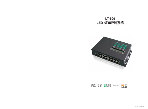
LT-600 LED 控制系统规格书
一
技术参数:
LT-600 LED 视频控制系统
工作电压: 输出信号信道: SPI输出: DMX输出: 输入输出端口: 灰度级别: 刷新频率: 联机传输方式: 12Vdc (配100-240Vac电源适配器) 16 路 Max 1364像素 × 16路 21824像素 Max 170像素 × 16路 2720像素 RJ45 最大65536级(64K) 60Hz~3000Hz TCP/IP 标准网络协议 产品尺寸: 包装尺寸: 重量: 脱机储存介质: SD卡容量: 第三方接口: 操作系统: SD记忆卡 2GB Max. DMX512/1990 协议 中、英文Windows 2000/ 2003/XP/Vista/7 L197XW120XH47(mm) L250XW125XH88(mm) 920g(净重) 1450g(毛重)
三
产品配件:
1. 网线 2. 信号线转换器 3. 电源适配器 4. SD 储存卡 5. SD读卡器 2 1 1 1 PCS PCS PCS PCS
16 PCS
网线
信号线转换器
电源适配器
SD 储存卡
SD读卡器
1
2
LT-600 LED lighting control system
LT-600 LED lighting control system
四
产品结构图:
( 2 ) 长按LOCK键锁定/解锁按键:
按键已锁
( 3 ) 按SETUP键进入设置DMX地址: 按MODE+/-增加或减少百位数, 按SPEED+/-增加或减少十位数, 按M1/M2增加或减少个位数。 按LOCK确认
二
功能特点:
1. 一台控制器简单集合了以往多款控制器才能达到的5大功能: ● 以太网实时电脑同步显示控制。 ● 脱机SD卡储存节目点播,节目、速度选择等功能在液晶屏一目了然。 ● 兼容DMX512 协议,连接DMX控制台构建灯光控制网络。 ● 支持WiFi无线传输,适合特殊场合,无需布线。 ● 支持任意时间自动定时播放,实现周一到周日、节假日播放不同节目。 2. 能直接输出DMX信号,也可以控制各种LED驱动芯片,基于如下IC驱动的LED灯具都可以控制: 74HC595, 6B595, MBI5026, DM134, ZQ9712, LPD6803, LPD6813, LPD1101, D705, UCS6909, UCS6912, UCS1903, UCS1909, UCS1912, UCS2903, UCS2909, UCS2912, WS2801, WS2803, WS2811,WS2812, WS2812b, HL1609, SM16716, SD600, P9813, LPD8803, LPD8806, LPD8809, LPD8812, TLS3001, TLS3002, TLS3003, TM1803, TM1804, TM1809, TM1812, MBI6120等等驱动IC。
东元伺服JSDE中文说明书12
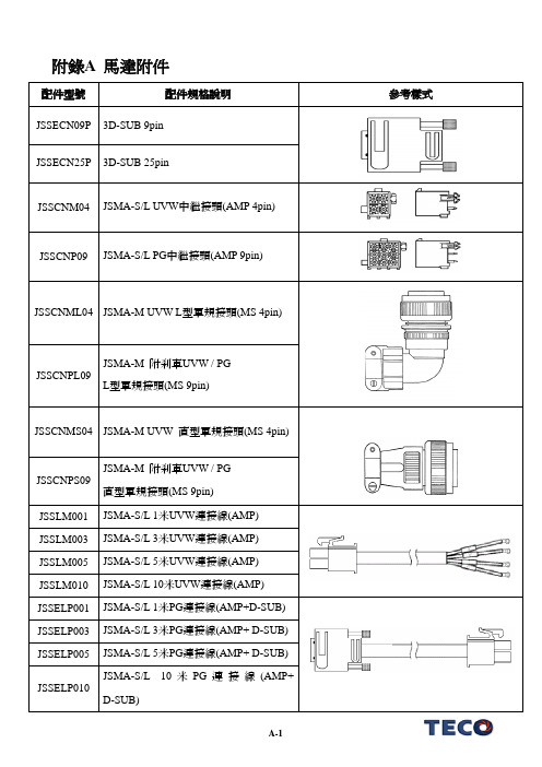
附錄A 馬達附件配件型號配件規格說明參考樣式JSSECN09P 3D-SUB 9pin JSSECN25P 3D-SUB 25pinJSSCNM04 JSMA-S/L UVW 中繼接頭(AMP 4pin)JSSCNP09JSMA-S/L PG 中繼接頭(AMP 9pin)JSSCNML04 JSMA-M UVW L 型軍規接頭(MS 4pin)JSSCNPL09JSMA-M 附剎車UVW / PGL 型軍規接頭(MS 9pin)JSSCNMS04 JSMA-M UVW 直型軍規接頭(MS 4pin)JSSCNPS09 JSMA-M 附剎車UVW / PG直型軍規接頭(MS 9pin)JSSLM001 JSMA-S/L 1米UVW 連接線(AMP) JSSLM003 JSMA-S/L 3米UVW 連接線(AMP) JSSLM005 JSMA-S/L 5米UVW 連接線(AMP) JSSLM010JSMA-S/L 10米UVW 連接線(AMP)JSSELP001 JSMA-S/L 1米PG 連接線(AMP+D-SUB) JSSELP003 JSMA-S/L 3米PG 連接線(AMP+ D-SUB) JSSELP005 JSMA-S/L 5米PG 連接線(AMP+ D-SUB)JSSELP010JSMA-S/L 10米PG 連接線(AMP+D-SUB)配件型號配件規格說明參考樣式JSSMLM001 JSMA-M 1米L 型UVW 連接線(MSL) JSSMLM003 JSMA-M 3米L 型UVW 連接線(MSL) JSSMLM005 JSMA-M 5米L 型UVW 連接線(MSL) JSSMLM010 JSMA-M 10米L 型UVW 連接線(MSL)JSSEMLP001JSMA-M 1米L 型PG 連接線(MSL+D-SUB)JSSEMLP003JSMA-M 3米L 型PG 連接線(MSL+D-SUB)JSSEMLP005JSMA-M 5米L 型PG 連接線(MSL+D-SUB)JSSEMLP010JSMA-M 10米L 型PG 連接線(MSL+D-SUB)JSSMSM001 JSMA-M 1米直型UVW 連接線(MSS) JSSMSM003 JSMA-M 3米直型UVW 連接線(MSS) JSSMSM005 JSMA-M 5米直型UVW 連接線(MSS) JSSMSM010 JSMA-M 10米直型UVW 連接線(MSS)JSSEMSP001JSMA-M 1米直型PG 連接線(MSS+D-SUB)JSSEMSP003JSMA-M 3米直型PG 連接線(MSS+D-SUB)JSSEMSP005JSMA-M 5米直型PG 連接線(MSS+D-SUB)JSSEMSP010JSMA-M 10米直型PG 連接線(MSS+D-SUB)。
微型芯片产品:振荡器快速参考指南说明书
ü
DSC2130/33
ü
DSC2240/44
ü
MX57
MX55
MX85
MXT57
MXT85
ü
ü
ü
ü
ü
ü
ü
ü
ü
ü
ü
ü
ü
ü
ü
ü
ü
ü
ü
ü
ü
ü
ü
ü
ü
ü
ü
ü
ü
ü
ü
ü
ü
ü
ü
ü
ü
ü
ü
ü
ü
ü
ü
ü
ü
ü
ü
ü
ü
ü
ü
ü
ü
üüü源自üüüü
ü
ü
ü
ü
ü
ü
ü
ü
ü
ü
ü
ü
ü
ü
ü
ü
ü
ü
ü
ü
ü
ü
Ultra-Low Jitter
Ultra-Low Jitter TCXO
3.2 x 2.5 14L
2.5 x 2.0 6L 7.0 x 5.0 6L 5.0 x 3.2 6L 3.2 x 2.5 6L 2.5 x 2.0 6L
3.2 x 2.5 14L
7.0 x 5.0 6L 5.0 x 3.2 6L 7.0 x 5.0 38L 7.0 x 5.0 6L 7.0 x 5.0 38L
Supply Current: 1.3 mA Ultra small package size: 1.6x1.2 mm
Resiient to shock and vibration AEC-Q100 Qualified
sICK ufs叉形传感器 操作手册说明书
UFS槽形传感器所说明的产品UFS制造商SICK AGErwin-Sick-Str.179183 Waldkirch, Germany德国法律信息本文档受版权保护。
其中涉及到的一切权利归西克公司所有。
只允许在版权法的范围内复制本文档的全部或部分内容。
未经西克公司的明确书面许可,不允许对文档进行修改、删减或翻译。
本文档所提及的商标为其各自所有者的资产。
© 西克公司版权所有。
原始文档本文档为西克股份公司的原始文档。
2操作指南 | UFS8028165/2022-11-14 | SICK如有更改,恕不另行通知内容内容1关于本文档的 (5)1.1关于操作指南的信息 (5)1.2适用范围 (5)1.3符号说明 (5)1.4更多信息 (6)1.5客户服务中心 (6)2安全信息 (7)2.1按规定使用 (7)2.2违规使用 (7)2.3责任范围 (7)2.4维修 (7)3产品说明 (8)3.1产品识别 (8)3.1.1铭牌 (8)3.2产品特点与功能 (8)3.2.1设备视图 (8)3.2.2产品特征 (9)4装配 (10)4.1供货范围 (10)4.2安装要求 (10)4.3安装设备 (10)5电气安装 (11)5.1关于电气安装的提示 (11)5.2接口的引脚分配 (12)5.2.1引脚分配 (12)5.2.2开关逻辑 (12)5.3连接工作电压 (12)5.4流程数据结构 UFS (13)6调试 (14)6.1以动态示教为例进行调试 (14)7操作 (15)7.1菜单结构 (15)7.2示教功能 (15)7.2.1通过操作面板示教 (16)7.2.2外部示教 (18)7.2.3错误示教 (19)7.3精调开关阈值 (19)7.4调整开关逻辑 (19)7.5按键锁 (20)8028165/2022-11-14 | SICK操作指南 | UFS3如有更改,恕不另行通知内容7.6通过 SOPAS 的其他设置选项和诊断选项 (20)7.6.1通过 SOPAS 示教 (20)7.6.2调整开关阈值 (20)7.6.3调整开关逻辑 (20)7.6.4按键锁 (20)7.6.5通过 SOPAS 的进一步设置 (21)8故障排除 (23)9维护 (24)9.1维护 (24)9.2清洁设备 (24)10停机 (25)10.1拆卸和废弃处理 (25)10.2寄回设备 (25)11技术数据 (26)11.1一般数据 (26)11.2尺寸图 (28)12配件 (30)13附件 (31)13.1欧盟合规性声明和证书 (31)13.2UL60947-5-2 认证 (31)13.3许可证 (31)4操作指南 | UFS8028165/2022-11-14 | SICK如有更改,恕不另行通知1关于本文档的1.1关于操作指南的信息本操作指南提供有关操作 SICK AG 公司设备的重要提示。
MCU说明书
5.3.2.3 电池均充 - 手工均充 .....................................64
5.3.2.4 电池类型 ................................................66
5.3.2.5 充电电流限制 ............................................67
5.3.3.4 校准电池电流 ............................................73
5.3.3.5 校准电池对称电压 ........................................74
5.3.3.6 校准交流电压 ............................................74
易达电源的软件专家门不断提高系统的远程通讯功能,采用了标准的网络协议。如果现场工作人 员使用非易达提供的图纸、指令或指导而造成系统的损坏,易达电源将不承担任何责任。
内容如有改变,恕不另行通知
4(88)
Document title
用户手册- Flatpack MCU (智能中文版)
Prepared by
2(88)
Document title
用户手册- Flatpack MCU (智能中文版)
Prepared by
Kelvin Wei / Winner Ming
Date (dd.mm.yyyy)
16.01.2006
5.3.1.2 告警设置/显示 ...........................................46
3.3.1
﹝用户信息﹞与﹝维护操作﹞与(工厂操作)
USBC9100使用手册 V3.2
使用手册USBC 9100工业级智能USB-CAN总线转换器USBC 9100[知识产权保护声明]使用UIROBOT产品前请注意以下三点:• UIROBOT的产品均达到UIROBOT使用手册中所述的技术功能要求。
• UIROBOT愿与那些注重知识产权保护的客户合作。
• 任何试图破坏UIROBOT器件代码保护功能的行为均可视为违反了知识产权保护法案和条列。
如果这种行为导致在未经UIROBOT授权的情况下,获取软件或其他受知识产权保护的成果,UIROBOT有权依据该法案提起诉讼制止这种行为。
[免责声明]本使用手册中所述的器件使用信息及其他内容仅为您提供便利,它们可能在未来版本中被更新。
确保应用符合技术规范,是您自身应负的责任。
UIROBOT对这些信息不作任何形式的声明或担保,包括但不限于使用情况、质量、性能、适销性或特定用途的适用性的声明或担保。
UIROBOT对因这些信息及使用这些信息而引起的后果不承担任何责任。
如果将UIROBOT器件用于生命维持和/或生命安全应用,一切风险由买方自负。
买方同意在由此引发任何一切伤害、索赔、诉讼或费用时,会维护和保障UIROBOT免于承担法律责任和赔偿。
未经UIROBOT同意,不得以任何方式转让任何许可证。
[商标和外观设计声明]UIROBOT 的名称和徽标组合为 UIROBOT Ltd.在中国和其他国家或地区的注册商标。
UIROBOT的UIM24XXX系列步进电机(控制)控制器和UIM25XX系列转换控制器外观设计均以申请专利保护。
[ USBC9100产品订购说明 ]在订购USBC9100产品时请按以名下格式提供产品号,以便我们准确及时地为您提供产品:USBC9100产品牌号类别USBC USB-CAN转换器系列1 = 单通道9 1 0 0第2页UC91130201CN UI Robot Technology Co. Ltd.工业级智能USB-CAN总线转换器USBC9100USB CAN工业级智能CAN转换器性能指标−尺寸: 72mm * 36mm * 11mm−系统性能: 32位处理器 48MIPS−帧流量: 业界最优性能,达到CAN的理论极限,实测每秒钟流量超过 6500 帧−传输方式: CAN接口透明转换,兼容CAN2.0A、CAN2.0B、CANOPEN 协议,USB 接口兼容 USB1.1和 USB2.0 协议−通道数目: 1 路,可叠加使用,最多100台, 形成100通道−传输介质: 屏蔽或非屏蔽双绞线−传输速率: CAN 控制器波特率在 125Kbps~1Mbps 之间可选−通讯接口: 标准CAN-bus 接口,起始端电阻自由配置−总线长度及节点数: 单路总线上最多可接 110 个节点,最长通讯距离 10 公里−供电形式: 使用 USB 总线电源,无需外部电源−占用资源: 即插即用,资源自动分配−工作温度: -40℃~+85℃−存储温度: -50℃~+105℃简介USBC9100是兼容 USB1.1 和 USB2.0 总线,带有 1 路 CAN 接口的工业级智能型 CAN数据接口卡采用 USBC9100智能CAN转换器,PC 可以通过 USB 总线连接至 CAN 网络,构成实验室、工业控制、智能小区等 CAN 网络领域中数据处理、数据采集。
- 1、下载文档前请自行甄别文档内容的完整性,平台不提供额外的编辑、内容补充、找答案等附加服务。
- 2、"仅部分预览"的文档,不可在线预览部分如存在完整性等问题,可反馈申请退款(可完整预览的文档不适用该条件!)。
- 3、如文档侵犯您的权益,请联系客服反馈,我们会尽快为您处理(人工客服工作时间:9:00-18:30)。
9路LED驱动电路-UCS1909
1. 概述:UCS1909是9路LED驱动电路,通过外围控制器可实现该电路单片灰度及级联
控制,广泛用于户外大屏幕,护栏管,装饰灯条等彩色点阵发光系统。
2. 特点:
输出口耐压高达40V
芯片内置稳压管,工作电压支持5~40V
256级灰度调节
单根信号线级联
数据信号经内部整形后输出,任意两点间连线可达10米以上
数据发送速度800Kbps/400Kbps可选
选择数据发送速度800Kbps,实现画面30帧/秒可级联1024点,15帧可达2048点
每帧数据发完所有IC同时锁存输出,避免出现前后画面不一样的现象
SOP14封装
3. 管脚定义:SOP14封装
4. 管脚功能描述:
序号 管脚名 I/O 功能描述
1 VDD --
电源
2 SET I
接VDD:400Kbps 悬空:800Kbps
3 DOUT O
数据输出
4~6 R,G,B O
LED驱动输出端
7 GND --
地
8~13 R,G,B O
LED驱动输出端
14 DIN I
数据输入
5. 电气参数:
符号 参数说明 条件 最小 典型 最大 单位
VDD 供电电压 4.5 5 6 V
Vled LED驱动输出端电 3 40 V
6. 电路功能描述:
电路采用单线通讯方式级联,数据用归零码发送。电路上电后,从DIN脚输入数据,
一个电路有9路LED输出端,即3组RGB。每路输出需要8位二进制数设置灰度,一组
RGB需要24位二进制数,数据高位先输入,结构如下:
R G B
0000_0000 ~ 1111_1111 0000_0000 ~ 1111_1111 0000_0000 ~ 1111_1111
8位二进制数从0000_0000到1111_1111对应每路的256级灰度,最小灰度(0000_0000)是
0,即LED不亮,1111_1111对应最大亮度。
一个电路需要共72位数据来设置各个RGB的灰度,数据输入顺序R1G1B1,R2G2B2,
R3G3B3。当输入的数据满72位后,电路开始转发数据,即将输入的数据经内部译码,编
码处理后从DOUT端输出进入下一级电路,从而实现多电路级联工作。当所有的电路都接
受到新的数据后,输入一个reset信号,新的数据生效。RGB端口根据输入的数据输出相应
的占空比信号,该信号刷新周期约1.5mS。
数据码型说明:高速模式(800kbps)
描述 典型时间 允许误差
T0H 0码高电平时间 250ns 150ns
T0L 0码低电平时间 1000ns 150ns
T1H 1码高电平时间 1000ns 150ns
T1L 1码低电平时间 250ns 150ns
Treset Reset码,低电平时间 24000ns 1000ns
如果是低速模式(400kbps),上述时间增加一倍。
压
Vout 数据输出端电压 0 5 V
Vin 输入电压 -0.5 VDD+0.5 V
Iout LED端驱动电流 Vled=0.8V 32 mA
Pdmax 最大功耗 Vled=0.8V 360 mW
Fmax 数据发送速率 VDD=5V 800 Kbps
Top 工作温度 -40 60 ℃
Tst 存储温度 -65 120 ℃
tPLH 输出上升时间 CL=15pF RL=10K 300 ns
tPHL 输出下降时间 100 ns
0码
1码
Reset码
T0H
T0L
T1H
T1L
Treset
级联示意图:
为保证第一帧输入的数据有效,在输入第一帧数据前先输入一个reset信号,每一帧数据最
先输入的72位进入IC1,之后是IC2,依次向后直到最后一个IC,所有的IC都输入了数据
后再输入reset信号,之后数据才生效,表示一帧数据完成。可以输入下一帧数据了。
N代表系统中IC个数。
注:为降低干扰和保护IC输入输出端,必须在电路DIN和DOUT端各串接一个39~50欧
姆电阻。
7. 电源配置:电路可以用6~40V供电,VDD脚对地电容0.1uF~10uF,应尽量靠近IC。
电源上串联的电阻根据VCC电压不同需要选择不同阻值。不能将VDD直接接高于5V的电
源。
电源电压VCC 串联电阻阻值(R1)
12V 3K(1/4W)
24V 9K(1/4W)
串联电阻阻值的计算以芯片工作电流(Idd)等于2.5mA为准。其计算公式如下:
R1=(VCC-5)/Idd
例如:VCC=6V,则R1=(6-5)/0.0025=0.4K
VCC=18V,则R1=(18-5)/0.0025=5.2K
8. 应用图:
reset N个72位数据 reset N个72位数据 reset
N个72位数据
reset
9. 封装外形尺寸图:SOP14