Research Tools for 3-D Mobile Ad-hoc Networking with Directional Antenna
RovingNetworks RN-171 数据手册说明书

RN-171-DS v3.0 11/1/2011WiFly GSX 802.11 b/g Wireless LAN ModuleFeatures∙ FCC / CE/ IC certified 2.4GHz IEEE 802.11b/g transceiver∙ Small form factor: 1050 x 700 x 130 mil ∙ Configurable transmit power: 0dBm to 10 dBm ∙ RF pad connector for antennas∙ Certified antennas: Chip antenna , 4” Dipole, PCB trace and wire antenna∙ Ultra-low power - 4uA sleep, 38mA Rx, 120 mA Tx at 0dBm∙High throughput - 921Kbps TX, 500Kbps RX data rate with TCP/IP and WPA2 over UART, upto 2Mbps over SPI slave∙ 8 Mbit flash memory and 128 KB RAM ∙ 10 general purpose digital I/O ∙ 8 analog sensor interfaces∙ Real-time clock for wakeup and time stamping ∙ Accepts 3.3V regulated power supply or 3V battery∙ Supports Adhoc and infrastructure networks ∙On board complete TCP/IP networking stack∙ Environmentally friendly- RoHS compliant. Applications∙ Remote Monitoring∙ Industrial sensors and controls ∙ Telemetry ∙Home AutomationDescriptionThe RN-171 module is a standalone complete TCP/IP wireless networking module. Due to its small form factor and extremely low power consumption, the RN-171 is perfect for mobile wireless applications such as asset monitoring, sensors and portable battery operated devices. It incorporates a 2.4GHz radio, 32-bit SPARC processor, TCP/IP stack, real-time clock, crypto accelerator, power management and analog sensor interfaces. This module is preloaded with firmware to simplify integration and minimizes development of your application. In the simplest configuration the hardware only requires four connections (PWR, TX, RX and GND) to create a wireless data connection. Additionally, the analog sensor inputs can be used to interface a variety of sensors such as temperature, audio, motion and acceleration. The ability to go into deep sleep mode and automatically scan and associate to an AP when awakemakesthe RN-171 suitable for roaming applications. The RN-171 also includes a built in HTML client to automatically post serial uart data or sensor data to a web server.Block Diagram RN-171-DS v3.0 11/1/2011Overview∙Host Data Rate u p to 921 Kbps TX, 500 Kbps RX for UART, up to 2Mbps over SPI slave∙Intelligent, built-in power management with programmable wakeup∙Real time clock for time stamping, auto-sleep and auto-wakeup∙Configuration using simple ASCII commands∙Software controlled transmit power (0dBm to 10dBm) for ultra low power applications∙Memory 128 KB RAM, 2MB ROM, 2 KB battery-backed memory, 8 Mbit Flash.∙Secure WiFi authentication WEP-128, WPA-PSK (TKIP), WPA2-PSK (AES)∙Built in networking applications DHCP, UDP, DNS, ARP, ICMP, TCP, HTML client∙802.11 power save and roaming functions∙Castellated pads for reliable solderingEnvironmental ConditionsParameter RN-171Temperature Range (Operating) -40 o C ~ +85 o CTemperature Range (Storage) -40o C ~ +85 o CRelative Humidity (Operating) ≤90%Relative Humidity (Storage) ≤90%Electrical Characteristics (Provisional)Supply Voltage Min Typ. Max. Unit Supply Voltage (VBATT option) 3.0 3.3 3.7 VDCDigital InputInput logic HIGH VIH 2.3V VDCInput logic LOW VIL 1.0V VDC Digital Output drivePIO 4,5,6,7,8 24 mAPIO 9,10,11,12,13 8 mA Power consumptionSleep 4 uAStandby (doze) - 15 - mAConnected (idle, RX) 40 mAConnected (TX)* 0dBm 120 mA 12dBm 190 mA*The transmit power can be controlled via firmwareAnalog Sensor InputsParameter Value Sense 0,1,2,3 wakeup detect threshold 500mVAD sense 0-7 measurement range 0-400mV (Do not exceed 1.2V DC) Resolution 14 bits = 12uVAccuracy 5% un-calibrated, .01% calibrated Minimum conversion time 35us (5kHz over Wi-Fi )Sensor Power (pin 33) output resistance 3.3V 10 ohms, max current = 50mA RN-171-DS v3.0 11/1/2011 Radio CharacteristicsParameter SpecificationsFrequency 2402 ~ 2480MHzModulation 802.11b compatibility : DSSS(CCK-11, CCK-5.5, DQPSK-2, DBPSK-1) 802.11g : OFDM (default)Channel intervals 5MHzChannels 1 - 14Transmission rate (over the air) 1 – 11Mbps for 802.11b / 6 – 54Mbps for 802.11g Receive sensitivity -83dBm typ.Output level (Class1) -2dBm to +12dBm (configurable via software) Transmit PowerOutput Power 802.11 b (2Mbps)Current in mA*802.11 g (24Mbps)Current in mA*0 120 1352 130 1504 170 1906 175 2008 180 21010 185 22512 190 240* Measured at 3.3VDC VCC. The power consumption is the average power, active during actual power consumption RN-171-DS v3.0 11/1/2011 Typical Application Circuit with battery boost circuit RN-171-DS v3.0 11/1/2011 Typical Application Circuit with linear regulatorRN-171-DS v3.0 11/1/2011Pin DescriptionPad Number Signal Name DescriptionOptional Function Direction 1 GND Ground2 Not Used Do not connect No Connect3 Not Used Do not connectNo Connect4 GPIO 9 Enable Adhoc mode, Restore factory defaults, 8mA drive, 3.3V tolerantINPUT/OUTPUT 5 GPIO 8 GPIO, 24mA drive, 3.3V tolerant INPUT/OUTPUT 6 GPIO 7 GPIO, 24mA drive, 3.3V tolerantINPUT/OUTPUT 7 GPIO 6 GPIO, 24mA drive, 3.3V tolerant, Connection STATUS on Roving Firmware Association to AP statusINPUT/OUTPUT 8 GPIO 5 GPIO, 24mA drive, 3.3V tolerant, Data Tx/Rx status INPUT/OUTPUT 9 GPIO 4 GPIO, 24mA drive, 3.3V tolerantConnected over TCP status INPUT/OUTPUT 10 VDD_3.3V 3.3V Power Supply11 GPIO 3 GPIO, 8mA drive, 3.3V tolerant INPUT/OUTPUT 12 GPIO 2 GPIO, 8mA drive, 3.3V tolerant INPUT/OUTPUT 13 GPIO 1 GPIO, 8mA drive, 3.3V tolerant INPUT/OUTPUT 14 GND Ground15 Not Used Do not connect No Connect 16 Not Used Do not connect No Connect 17 Not Used Do not connect No Connect 18 Not Used Do not connect No Connect 19 Not Used Do not connect No Connect 20GND Ground 21, 22, 23 GNDGround24ANTENNA 802.11b/g 2.4Ghz antenna 25, 26, 27 GND Ground 28 GNDGround29 SENSOR 0 Sensor Interface, Analog input to module, 1.2V tolerantINPUT 30 SENSOR 1 Sensor Interface, Analog input to module, 1.2V tolerantINPUT 31 SENSOR 2 Sensor Interface, Analog input to module, 1.2V tolerantINPUT 32 SENSOR 3 Sensor Interface, Analog input to module, 1.2V tolerantINPUT 33 SENSOR POWER Output voltage from module, 3.3V Max34VDD_3.3V_RF3.3V RF Power Supply (connect to 3.3V rail)481202127284749Module DimensionsTOP VIEW RN-171-DS v3.0 11/1/2011INPUT35 SENSOR 4 Sensor Interface, Analog input to module, 1.2Vtolerant36 SENSOR 5 Sensor Interface, Analog input to module, 1.2VINPUTtolerantINPUT37 SENSOR 6 Sensor Interface, Analog input to module, 1.2VtolerantINPUT38 SENSOR 7 Sensor Interface, Analog input to module, 1.2Vtolerant39 GND GroundINPUT40 RESET Optional Module Reset Signal (active low),100k Pull up, apply pulse of at least 160us,3.3V TolerantINPUT41 FORCE_AWAKE Optional Module Awake Signal (active high),100k pull down, apply pulse of at least 260us,3.3V Tolerant42 GPIO 14 GPIO, 8mA drive, 3.3V tolerant INPUT/OUTPUTOUTPUT43 UART_RTS UART RTS flow control, 8mA drive, 3.3Vtolerant44 UART_CTS UART CTS flow control, 3.3V tolerant INPUT45 UART_RX UART RX, 3.3V tolerant INPUT46 UART_TX UART TX, 8mA drive, 3.3V tolerant OUTPUT47 GND Ground48 SREG_3V3_CTRL Boost Regulator Control OUTPUT49 VDD-BATT Battery input, 2.0-3.3V with boost regulator inuse, connect to VDD if not using boostregulatorNOTE #1: Signals marked as INPUT are input to the RN-171 module. Signals marked as OUTPUT are output from the moduleNOTE #2: Any of the sensors 0-3 can be used to wake the module. The sensor pins are 1.2V tolerant. DO NOT apply 3.3V on these pins. DO NOT apply 3.3V on any of sensor pins.NOTE #3: When sensor pins are used as sensor inputs, they saturate at 400mV. Sensor pins will accept input voltages up to 1.2V but will saturate at 400mV. DO NOT apply 3.3V on any of sensor pins. RN-171-DS v3.0 11/1/2011 Physical DimensionsRN-171 Module Dimensions (Top view)RN-171 FootprintRecommend footprint pad size: 40 mil x 90 milNOTE: 1 mil = 0.0254 millimeters RN-171-DS v3.0 11/1/2011Design ConcernsAntenna Design.1. PCB Trace Antenna: A recommended PCB trace Antenna pattern is shown below. The antenna groundshould be connected with at least 2 vias to the ground plane and / or ground polygon on both top and bottom layers.The ground plane should come close to the antenna, exactly where shown in the diagram. The distance is critical. There should be no ground place / trace under the antenna, under any circumstance.The antenna feed will go through the polygon on a 50 ohm impedance trace to the source of the signal.Unless the antenna trace is exactly 50 ohm and the source has a 50 ohm output impedance a matching PI filter should be used (2 capacitors and an inductor).The left side of the antenna should be placed on the PCB edge. If not possible please leave at least 1 inch of clearance from any trace or ground plane. The top and bottom of the antenna (the shorter side) should either be placed on the PCB edge or have at least 1 inch clearance from any trace or ground plane.To control the impedance of the antenna feed the board should be a 4 layer board with a dedicated ground plane and a thickness of around 8-14 mil between the ground plane and the top layer (where the antenna feed is routed).A two layer board would not be thin enough to obtain the desired impedance using a decent width for the trace.Antenna feedAntenna GroundThe trace form the RF pad to the antenna feed should be of 12mil thickness on a four layer PCB to achieve 50 ohms impedance matching. This is shown in the diagram below: RN-171-DS v3.0 11/1/201112 mil thick trace from RF pad to antenna feed RN-171-DS v3.0 11/1/20112. Chip Antenna: A recommended chip antenna is the FR05-S1-N-0-104manufactured by Fractus. Please refer to its data sheet and user guide for additional information.A recommended chip antenna layout is shown below. Impedance matching components are required to match the antenna impedance to 50 ohms. A recommended value is using a 3.3nH inductor and a 1.8pF capacitor as shown in the diagram below.2127 RN-171-DS v3.0 11/1/20113. Wire Antenna: To implement a wire antenna, drill hole through the board on the RF pad (pin 24) to place the wire antenna. To provide an impedance match of 50 ohms, the RF path from the RF pad (Pin 24) to the location of the wire antenna should be of 12 mil thickness on a four layers PCB. Please refer to the diagram below. It is recommended to use a 18 gauge wire on length 1 inch ± 0.25 inch. For best performance, the wire antenna should be perpendicular to the ground plane.NOTE: There should be no thermal relief connectors on GND for RF path and on the Ground plane.212724 RN-171-DS v3.0 11/1/20114. U.FL. connectorAn example to implement an U.FL. connector is shown below. The trace from the RF pad to the U.FL connector should be of 12 mil thickness to achieve 50 ohm impedance matching on a four layer board.The part number of the U.FL. connector used for certification of the module is U.FL-R-SM from Hirose.RN-171-DS v3.0 11/1/2011Using Batteries The RN-171 module does not have a Boost Regulator circuit. This makes the choice of batteries absolutely critical because if the battery voltage drops below 3V, the module performance will start to degrade.. One possible battery of choice is the ER14505 3.6V battery. This battery is known to have a long battery life. If this battery is used to power the module, it is recommended that you use a 1000uF to 3000uF bypass capacitor as the ER14505 battery has high output impedance.Boost Regulator: The RN-171 does not have a boost regulator on board. A recommended circuit for the boost regulator is shown below.Designs that include the boost regulator will provide good supply to the flash even when the battery voltage drops close to 1.8V.If a board containing RN-171 does not include the boost regulator, it SHOULD include a 2.7V undervoltage reset circuit to prevent the module from accessing flash when supply voltage falls below 2.7V. All supported flash chips are rated for minimum VDD of 2.7V.Recommended values of the parts for the Boost Regulator circuit are:Designator Description Value Manufacturer Manufacturer PNVendor Vendor PND Diode Schottky 1A 20V SMA SS12 Micro Commercial CoSS12-TP DigiKey SS12-TPCT-NDL Inductor 1.0uH 30% SMD1uH Taiyo Yuden NR3015T1R0N DigiKey 587-1647-1-NDQ MOSFET N-CH 20V 5.9 A DMN2050L Diodes Inc. DMN2050L-7 DigiKey DMN2050LDICT-NDIt is recommended to use a low voltage detector circuit such as XC61 from Torex tied to the RESET pin of the RN-171 module to protect from low voltage.Powering from a 3.3V Regulated Source: Apply 3.3V regulated power to pins 10, 34 and 49. Leave pin 48 (SREG_3V3_CTRL) unconnected. Do not connect pin 48 to ground. leave it as unconnected.48 SREG_3V3_CTRL49 VDD_BATTVBATT19 VDD 34 VDD_RF RN-171C inC Out RN-171-DS v3.0 11/1/2011Solder Reflow. Reflow temperature must not exceed 220C.To reflow solder the RN-171 module onto a PCB Roving recommends a RoHS compliant solder paste equivalent to the NIHON ALMIT paste or OMNIX OM-310 solder paste from Alpha metals.NOTE: Use no clean Flux, Do NOT water wash!Note also, that the temperature profile is based on the IC level and other components level only (without the shield can). So if we go on module perspective, above 245C profile should be acceptable. RN-171-DS v3.0 11/1/2011 RN-171-DS v3.0 11/1/2011 Ordering InformationPart Number DescriptionRN-171 Industrial Temperature (- 40 to + 85 C) with RF pad for external antennaRN-174Development board for RN-171 module containing RS-232 and TTL UART hardware interface, status LEDs, power regulator, sensor connectionsRN-SMA4-RP 4” external antenna with reverse polarity SMA connector. Used with RN-UFL-SMA6RN-UFL-SMA6 6 inch cable with U.FL connector on one end and SMA on the otherFor other configurations, contact Roving Networks directly.Visit for current pricing and a list of distributors carrying our products.Copyright © 2011 Roving Networks. All rights reserved.Roving Networks reserves the right to make corrections, modifications, and other changes to its products, documentation and services at any time. Customers should obtain the latest relevant information before placing orders and should verify that such information is current and complete.Roving Networks assumes no liability for applications assistance or customer product design. Customers are responsible for their products and applications using Roving Networks components. To minimize the risks associated with customer products and applications, customers should provide adequate design and operating safeguards.Roving Networks products are not authorized for use in safety-critical applications (such as life support) where a failure of the Roving Networks product would reasonably be expected to cause severe personal injury or death, unless officers of the parties have executed an agreement specifically governing such use.All other trademarks are property of their respective owners.。
一种3D MIMO增强的物理层安全方法

一种3D MIMO增强的物理层安全方法孟庆民;刘传顺;岳文静;曾桂根【摘要】由于具有把Multiple-Input Multiple-Output(MIMO)处理从方位角扩展到仰角的能力,三维MIMO (3D MIMO)技术在近年来引起越来越多的关注.研究适合的三维空间信道模型(3D SCM)是3D MIMO技术研究的一个基本步骤.在回顾了二维信道模型和一种三维双极化信道模型之后,提出了一种3D MIMO增强的物理层安全方法,研究了基站天线下倾角、移动台天线仰角对期望用户安全容量的影响.此外,还评估了相邻小区干扰的影响.【期刊名称】《微型机与应用》【年(卷),期】2015(034)014【总页数】4页(P71-73,80)【关键词】MIMO通信;三维信道模型;安全容量【作者】孟庆民;刘传顺;岳文静;曾桂根【作者单位】南京邮电大学信号处理与传输研究院,江苏南京210003;南京邮电大学无线传感器与宽带无线通信教育部重点实验室,江苏南京210003;南京邮电大学信号处理与传输研究院,江苏南京210003;南京邮电大学无线传感器与宽带无线通信教育部重点实验室,江苏南京210003;南京邮电大学信号处理与传输研究院,江苏南京210003;南京邮电大学无线传感器与宽带无线通信教育部重点实验室,江苏南京210003;南京邮电大学信号处理与传输研究院,江苏南京210003;南京邮电大学无线传感器与宽带无线通信教育部重点实验室,江苏南京210003【正文语种】中文【中图分类】TN929.50 引言近年来,随着5G研究的进展,三维空间信道模型引起了学术界和工业界越来越多的关注。
3GPP/3GPP2的25.996规范[1]定义了基于几何的二维空间信道模型,该信道模型仅考虑水平维度方位角的功率谱,而3D SCM改进之处在于同时考虑水平和垂直维度的功率谱。
在基站端采用大规模阵列天线的情况下,3D SCM可能增加实际信道建模的准确性。
ASRock WiFi-802.11n Module Operation 说明书

ASRock WiFi-802.11n ModuleOperation Guide1. IntroductionASRock WiFi-802.11n module is an easy-to-use wireless local area network (WLAN) adapter to support WiFi+AP function. With ASRock WiFi-802.11n module, you can easily create a wireless environment and enjoy the convenience of wireless network connectivity. Therefore, from anywhere within the signal range, you will be able to play LAN games, connect to the internet, access and share printers, and make Internet phone calls easily. Please read this operation guide carefully before you start to set up ASRock WiFi-802.11n module.1.1 SpecificationsStandard - IEEE 802.11nData Rate - 15, 30, 45, 60, 90, 120, 135, 150Mbps Security - AES, TKIP, WEPNetwork Architecture Types - Access Point mode (AP mode)- Station mode: Infrastructure mode andAd-Hoc modeFrequency Band - 2.4GHz ISM radio bandOperating Range - Indoor: 330ft (100m)- Outdoor: 980ft (300m)* The range varies in differentenvironments- up to 16 stationsNumber of Connected Devices(AP Mode)Antenna - ASRock WiFi-802.11nomni-directional antennaLED - Green data transmission (AIR) LED Support OS - Windows® XP / XP 64-bit / Vista TM /Vista TM 64-bitCompatibility - Full compatible with IEEE 802.11nstandard productsSoftware Support - ASRock WiFi-802.11n Wizard1.2 LED Indicators and Antenna PortsASRock WiFi-802.11n module has a green LED for transmission status mountedonboard, and two antenna ports for connection to the external antennas.LED Status IndicationOn Power on, transmit/receive/site survey OffPower off, no wireless connection1.3 Signal RangeThe signal range of ASRock WiFi-802.11n module varies from the operatingenvironment. Obstacles such as walls and metal barriers could reflex and absorb ratio signals. Devices like microwave ovens may also interfere with the wireless network greatly.Signal range:Indoor 330ft (100m), outdoor 980ft (300m)By default, ASRock WiFi-802.11n module should automatically adjust the data rate. The closer the wireless stations are the better the signal and transmission speed they will receive.Note:* To reach higher data rate, we advise users to adjust the channel bandwidth of Wireless AP to 40MHz instead of 20MHz. However, under the circumstances of a noisy environment, users may adjust the setting back to 20MHz, which may get less interference.Antenna PortsLED2. Hardware & Software Installation2.1 System RequirementsBefore installing ASRock WiFi-802.11n module to your motherboard, please make sure your system satisfies the following requirements.1.ASRock motherboard with a USB/WiFi (yellow), WiFi (black) or WiFi/E (black)header. (Please refer to ASRock motherboard manual for the location ofUSB/WiFi, WiFi or WiFi/E header.)USB/WiFi Header (2 x 6 Pin) WiFi Header (2 x 6 Pin) WiFi/E Header (2 x 8 Pin)2. A minimum of 256MB system memory3. Operating system: Windows® XP / XP 64-bit / Vista TM / Vista TM 64-bit4. An optical drive / CD-ROM for driver and utility installation2.2 Installing ASRock WiFi-802.11n Module and AntennasAfter you make sure your system satisfies the requirements above, please follow below steps for installing your ASRock WiFi-802.11n module. If the motherboard you purchase is equipped with ASRock WiFi-802.11n module, which is screwed next to the audio jack of the I/O panel, please skip step 2 to 6.1. Shut off the PC before installing ASRock WiFi-802.11n module.2. Move out your motherboard from the chassis.3. Fasten the bracket to the proper position of the chassis with screws.4. Plug ASRock WiFi-802.11n module with its connector-side to the USB/WiFi (yellow), WiFi (black) or WiFi/E (black) header on the motherboard. (The location of the USB/WiFi, WiFi or WiFi/E header may vary on motherboard models. Pleaserefer to your motherboard manual for the motherboard layout.)5. Fasten ASRock WiFi-802.11n module to the motherboard with screws.Connector-sideUSB/WiFi, WIFI or WIFI/E Header6. Place your motherboard to the chassis.7. Connect the cable-end from the antennas to the antenna ports on ASRockWiFi-802.11n module.8. Place the antennas at an elevated location. A wide and open position will enhance the operating range.Note:* You may connect two antennas to ASRock WiFi-802.11n module. However, please place the two antennas apart for a distance of at least 50cm and put them on different elevation of height to avoid interference of each others.2.3. Driver and Utility InstallationAfter you finish the hardware installation, you need to install WiFi driver and utility to your system. Please boot your system and follow below steps to install the WiFi driver and utility.1. Insert ASRock motherboard support CD to the optical drive.2. The system will automatically display the driver menu. Click “ASRockWiFi-802.11n Driver and Utility” and follow screen instructions to finish the driver installation.After above steps, the WiFi driver and utility are installed to your system simultaneously.Note:* Microsoft® had released a hotfix to improve the connectivity and performance of wireless network in Windows® Vista-based system. To download the hotfix, please go to:/kb/928152/en-us* Microsoft® had also released three hotfix to improve the connectivity for transferring large file in Windows® Vista-based system. Please go to:z /kb/932045/en-us to download the necessary hotfix when thissituation happened: "The connection has been lost" – this error message may occur when you try to copy a large file from one Windows ® Vista-based computer to another Windows Vista-based computer. z/kb/932170/en-us to download the necessary hotfix when this situation happened: When you copy large files to or from earlier operating systems, the copy operation may be slower than expected on some Windows ® Vista-based computers. z/kb/931770/en-us to download the necessary hotfix when this situation happened: The copy process may stop responding when you try to copy files from a server on a network to a Windows ® Vista-based computer.2.4 Utility SetupAfter you have installed the driver and utility to your system, now you are ready to set up the utility in your network. ASRock WiFi-802.11n module supports two kinds of wireless network mode: Access Point Mode (AP Mode) and Station Mode. Please refer to below introduction and select the most appropriate mode when setting it up.A. Access Point Mode (AP Mode)If you want to share the Internet access with the wireless stations in yourenvironment, such as PC, notebook and other devices, you can configure ASRock WiFi-802.11n module in an access point mode (AP mode). In this mode, ASRock WiFi-802.11n module becomes the wireless access point that provides local area network and Internet access for your wireless stations. The AP Mode feature is ideal for home/SOHO networks with several computers, a shared printer, and a shared Internet connection.InternetADSL or Cable Modem (if any)Printer 1Station 1Station 2Station 3Station 4ASRock MB With WiFi-802.11n ModuleB.Station ModeIf you do not plan to use AP function with ASRock WiFi-802.11n module, but just want to use the wireless function to connect the access point (AP), or connectwith other stations in the wireless range instead, please set up ASRock WiFi-802.11n module in station mode. There are two choices provided in station mode: Infrastructure mode and Ad-hoc mode. Please read below introduction for the differences of these two modes.B-1. Infrastructure ModeIf you have a present access point (AP) in your wireless network environment for this station to join, you can set up ASRock WiFi-802.11n module in Infrastructure mode. In this mode, ASRock WiFi-802.11n module acts as a wireless adapter. In other words, it is centered on an AP that provides Internet access and LAN communication for the wireless stations, such as PC, notebook and other devices.Internet ADSL or Cable Modem(if any)Station2Station1Access PointASRock MB With WiFi-802.11nModuleB-2. Ad-hoc ModeIf you don’t have a present access point in your wireless network environment, you can set up ASRock WiFi-802.11n module in Ad-hoc mode. The wireless network brings together workstations, PC, notebook and other devices for wireless communication.Station 2Station 1ASRock MB WithWiFi-802.11nModule3. General Setup with ASRock WiFi-802.11n WizardIf you want to easily set up ASRock WiFi-802.11n for general use, please use ASRock WiFi-802.11n Wizard and follow below procedures according to the mode you choose.Here we take Windows® Vista TM for example in the following pictures. Sincethe setup procedures are quite similar in different operating systems, please refer to below procedures when setting up ASRock WiFi-802.11n wizard under other operating systems.3.1 Setting up the AP Mode1. Move your mouse cursor to the icon on the Windows® taskbar andright-click the icon.2. Select Wizard to launch the WiFi setup wizard.3. Select Create a wireless access point and click Next.4. The system will automatically generate a SSID for the AP mode. You can rename the SSID if you want.5. Select a Network Security level for your AP mode. The configurable options are None, WEP, WPA-Personal and WPA2-Personal. Select an appropriate level and click Next.7. Select your Internet connection and click Next.3.2 Setting up the Station ModeNote:* Please be noted that the wizard for WiFi-802.11n Module does not provides Ad-Hoc mode. If you want to set up Ad-Hoc mode, please refer to page 26 - page 36 for advanced setup.3.2.1 Setting up the Infrastructure Mode1. Move your mouse cursor to the icon on the Windows® taskbar and right-click the icon.2. Select Wizard to launch the WiFi setup wizard.3. Select Join an existing wireless network and click Next.4. Click Finish to exit the wizard.5. Move your mouse cursor to the Wireless Network Connection icon on the Windows® taskbar and right-click the icon. Click Connect to a network to select available internet network.6. Choose an available internet network and click Connect.* If you choose a security-enabled wireless network, you have to input the network key.7. Your system is now connecting to a network.8. You have connected to internet wireless network successfully. If you want to start the connection automatically next time, you may save the network by checking Save this network box, and click Close.4. Advanced Setup in ASRock WiFi-802.11n UtilityIf you want to set up ASRock WiFi-802.11n module for advanced use, please follow below procedures according to the mode you choose. For general users, it is unnecessary to read below advanced setup of ASRock WiFi-802.11n module.Here we take Windows® Vista TM for example in the following pictures. Sincethe setup procedures are quite similar in different operating systems, please refer to below procedures when setting up ASRock WiFi-802.11n wizard under other operating systems.4.1 Setting up the AP ModeIf you want to set up ASRock WiFi-802.11n module for advanced use in AP mode, please use ASRock WiFi-802.11n utility and follow below steps according to the operating system you install.1.Double-click the utility shortcut on the desktop or double-click theicon on your Windows® taskbar to open the setup utility.2. Refer to the mode indicator on the top-right corner of the main window to know which mode ASRock WiFi-802.11n is in. If it is in station mode, click the mode switch button to switch it to AP mode.3. The system will automatically generate a SSID for the AP mode. You can rename the SSID if you want.4. Select a Network Authentication for your AP mode. The configurable options are Open System, Shared Key, WPA-PSK and WPA2-PSK. Select an appropriate one.Note:* If your operating system is Windows® XP with Service Pack 2, it is required to install the Microsoft hotfix in order to support WPA2-Personal function. Please go to this link to download the necessary hotfix:/downloads/details.aspx?familyid=662BB74D-E7C1-48D6-95EE-145923 4F4483&displaylang=en5. If you select Open System, the configurable options of Data Encryption are Noneand WEP for you to choose. This option allows you to select Key Length.6. If you select Shared Key, the configurable options of Data Encryption is WEPonly. This option allows you to select Key Length.7. If you select WPA-PSK, the configurable option of Data Encryption is TKIP only. You can’t select Key Length in this option.8. If you select WPA2-PSK, the configurable option of Data Encryption is AES only. You can’t select Key Length in this option either.9. In this case, we select Open System for the rest of the setups. If you select WEP, please select the Key Length. The configurable options are 64 Bits and 128 Bits. (However, if you select None in the Data Encryption, you will not be able to choose the Key Length.)10. Key in the Network password and click Apply to confirm.11. Click ICS (Internet Connection Sharing) button on the left-bottom corner of the main window.12. Select the correct internet connection and click Apply.Note:* You need to have another LAN connector connected to your ADSL / cable modem, and already set it up for Internet access. Please refer to the manual from your ISP for detailed setup steps.13. The AP mode configuration is completed.4.2 Setting up the Station ModeThere are two choices provides in station mode: Infrastructure mode and Ad-hoc mode. For the differences of Infrastructure mode and Ad-hoc mode, please refer to page 5 and 6 for details.If you want to set up ASRock WiFi-802.11n module for advanced use in station mode, please use Windows® configuration and follow below steps according to the mode you choose and the operating system you install.4.2.1 Setting up the Infrastructure ModeFor Windows® XP / XP 64-bit:1.Move your mouse cursor to Wireless Network Connection icon on theWindows® taskbar and right-click the icon.2.Select View Available Wireless Networks.3.Choose an available wireless network. Click Connect.4.If you choose a security-enabled wireless network, input the network key andclick Connect.5.You are now connected to a internet wireless network successfully.For Windows® Vista TM / Vista TM 64-bit:1.Click Start. Click Settings. And select Control Panel.2.Click Network and Internet.3.Click Network and Sharing Center.4.Click Connect to a network.5.Choose an available network and click Connect.6.If you choose a security-enabled wireless network, input the network key andclick Connect.7.You have connected to internet wireless network successfully. If you want to startthe connection automatically next time, you may save the network by checking Save this network box, and click Close.4.2.2 Setting up the Ad-hoc ModeFor Windows® XP / XP 64-bit:1.Move your mouse cursor to Wireless Network Connection icon on theWindows® taskbar and right-click the icon.2.Select View Available Wireless Networks.3. Click Change advanced settings.4.Switch to Wireless Networks tab and click Advanced.5. Select Computer-to-computer (ad hoc) networks only and clear the Automatically connect to non-preferred networks box if it is selected. ClickClose.6. On the Wireless Networks tab, click Add. In the Wireless Network Propertiesdialog box, specify a Network name (SSID). Click OK to close all dialog boxes.7. Select the Network Authentication for advanced setups. The configurable options are Open, Shared and WPA2-None. Select an appropriate one.8. If you select Open, the configurable option of Data Encryption is WEP only. Youmay select Disabled or WEP. This option allows you to select Key Index.9. If you select Shared, the configurable option of Data Encryption is WEP only. Youmay select Disabled or WEP. This option allows you to select Key Index.10. If you select WPA-None, the configurable options of Data Encryption are TKIP and AES. You may select either TKIP or AES. You can’t select Key index in this option.11. Launch View Available Wireless Networks again. You are now in Ad-hoc network, you may wait for other users to connect you or you may select the desired ad-hoc network and click Connect.For Windows® Vista TM / Vista TM 64-bit:1.Click Start. Click Settings. And select Control Panel.2.Click Network and Internet.3.Click Network and Sharing Center.4.Click Manage wireless networks.5.In the Manage wireless networks that use (Wireless Network Connection)window, click Add.6.Click Create an ad hoc network.7.In the Set up a wireless ad hoc network window, click Next.8.Specify a network name, select the security type. The configurable options are NoAuthentications (Open), WEP and WPA2-Personal.9. Select an appropriate one, and key in the security password. Then click Next.10.You have completed setting up an Ad-hoc network. Click Close to exit.11. You are now in Ad-hoc network, you may wait for other users to connect you or you may select the desired ad-hoc network.。
TechNote_MultiAntennaTech
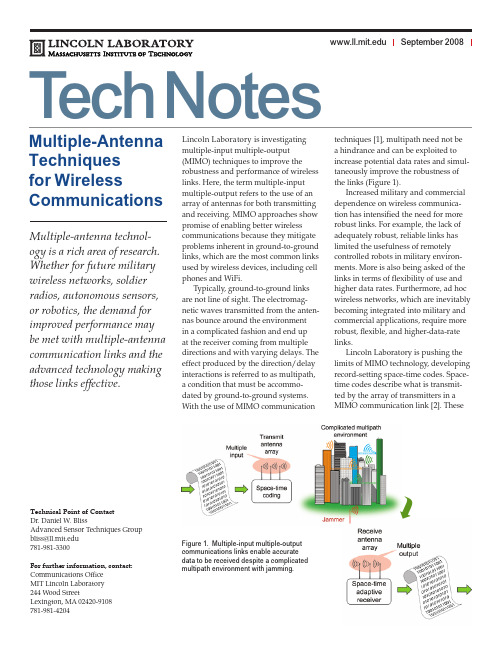
Lincoln Laboratory is investigating multiple-input multiple-output (MIMO) techniques to improve the robustness and performance of wireless links. Here, the term multiple-input multiple-output refers to the use of an array of antennas for both transmitting and receiving. MIMO approaches show promise of enabling better wireless communications because they mitigate problems inherent in ground-to-ground links, which are the most common links used by wireless devices, including cell phones and WiFi.Typically, ground-to-ground links are not line of sight. The electromag-netic waves transmitted from the anten-nas bounce around the environmentin a complicated fashion and end upat the receiver coming from multiple directions and with varying delays. The effect produced by the direction/delay interactions is referred to as multipath, a condition that must be accommo-dated by ground-to-ground systems. With the use of MIMO communication techniques [1], multipath need not be a hindrance and can be exploited to increase potential data rates and simul-taneously improve the robustness of the links (Figure 1).Increased military and commercial dependence on wireless communica-tion has intensified the need for more robust links. For example, the lack of adequately robust, reliable links has limited the usefulness of remotely controlled robots in military environ-ments. More is also being asked of the links in terms of flexibility of use and higher data rates. Furthermore, ad hoc wireless networks, which are inevitably becoming integrated into military and commercial applications, require more robust, flexible, and higher-data-rate links.Lincoln Laboratory is pushing the limits of MIMO technology, developing record-setting space-time codes. Space-time codes describe what is transmit-ted by the array of transmitters in a MIMO communication link [2]. These September 2008 Multiple-AntennaTechniquesfor WirelessCommunicationsMultiple-antenna technol-ogy is a rich area of research.Whether for future militarywireless networks, soldierradios, autonomous sensors,or robotics, the demand forimproved performance maybe met with multiple-antennacommunication links and theadvanced technology makingthose links effective.Technical Point of ContactDr. Daniel W. BlissAdvanced Sensor Techniques Groupbliss@781-981-3300For further information, contact: Communications OfficeMIT Lincoln Laboratory244 Wood StreetLexington, MA 02420-9108781-981-4204Figure 1. Multiple-input multiple-outputcommunications links enable accuratedata to be received despite a complicatedmultipath environment with jamming.codes employ advanced coding con-cepts along with sophisticated iterative receivers. The Laboratory-developed codes, which are allowing the largest data rates for a given transmit power, have been demonstrated theoretically and experimentally.Advanced Receiver TechniquesThe Laboratory has also developed and demonstrated advanced receiver techniques that enable communication in the presence of interference and jam-ming without significant degradation in link performance [3]. The diversity provided by multiple transmitting antennas allows the system to avoid signal interference, and the multiple receiving antennas allow the system to mitigate the effects of interference. Mitigation is achieved by subtracting the jamming and interference compo-nents of the signal seen at one receiv-ing antenna from signals received at other antennas. While the idea of using multiple antennas to null or mitigatejammers is not new, the Laboratory has pushed these approaches significantly and achieved remarkable mitigation performance in a variety of applications (communications, geolocation, GPS).Space-time adaptive processing (STAP) is a class of techniques used to improve mitigation performance. In this context, “space” refers to the multiple antennas and “time” refers to delay variations caused by multipath. The STAP approaches, which allow for improved matching of the signals seen at the receiving antennas, enable the subtraction to work better; therefore, jammer mitigation is improved.Opinions, interpretations, and recommendations herein are not necessarily endorsed by Lincoln Laboratory’s government sponsors. Work described in this document is performed under the prime contract with the U.S. Air Force, FA8721-05-C-0002.With the use of MIMO communica-tion techniques, multipath need not be a hindrance and can be exploited to increase potential data rates and simultaneously improve the robust-ness of wireless links.Without using multiple-antenna miti-gation techniques, a typical communica-tion link would simply fail or at best be forced to reduce its data rate by factors of thousands to millions, making the links effectively useless. Advanced mitigation techniques such as STAP make the loss in performance essentially negligible.Joint Transmit/Receive ArraysThe Laboratory is also extending its MIMO research to include the adaptive use of joint transmitting and receiv-ing antenna arrays. In order to do this, the transmitter must have an estimate of the channel, i.e., the environment between the transmitting antenna array and the receiving antenna array. Given this estimate of the channel, the transmitter can make intelligent deci-sions that improve performance of the intended link while simultaneously reducing interference to other commu-nication links.Extreme examples of this joint trans-mitter and receiver adaptation have been demonstrated theoretically and experimentally [4]. In one example, a node with separate transmitting and receiving antenna arrays optimizes the space-time coding such that the receiv-ing antennas are protected from the transmitted energy. The residual self-interference signal power is mitigated using advanced receiver techniques such as STAP and temporal-interference mitigation (Figure 2).By combining these techniques with a mechanical design that provides natu-ral transmitter-to-receiver isolation, it may be possible to build full-duplex nodes that simultaneously transmit and receive at the same frequency. This approach would break one of the fundamental bottlenecks in wireless networking: nodes that operated in a half-duplex mode had to choose to either transmit or receive at a given frequency. This full-duplex-node tech-nology makes possible various military and commercial applications, such as wireless data networks and robotics systems.References[1] D.W. Bliss, K.W. Forsythe, andA.M. Chan, “MIMO wireless commu-nication,” Lincoln Laboratory Journal , vol. 15, no. 1, pp. 97–126, 2005. [2] A.R. Margetts, K.W. Forsythe, andD.W. Bliss, “Direct space-time GF(q) LDPC modulation,” Conference Record of the Fortieth Asilomar Conference on Signals, Systems & Computers , Pacific Grove, Calif., October 2006. [3] D.W. Bliss, “Robust MIMO wirelesscommunication in the presence of interference using ad hoc antenna arrays,” Proceedings of MILCOM 03 (Boston), October 2003.[4] D.W. Bliss, P .A. Parker, and A.R.Margetts, “Simultaneous transmis-sion and reception for improved wire-less network performance,” Conference Proceedings of the IEEE Statistical Signal Processing Workshop, August 2007.Figure 2. A full-duplex relay employing self-interference mitigation may provide the ability to build full-duplex nodes that simultaneously transmit and receive at the same frequency.。
802.11简介

Key Features
TDLS Discovery TDLS Setup/Teardown TDLS U-APSD TDLS Peer Power Save Mode TDLS Channel Switching
NAS Drive 11n Radio
AP 11gRadio
TDLS
802.11 -2012
802.11n High Throughput (>100 Mbps)
802.11W Management Frame Security
PHY
2
IEEE 802.11 Revisions
MAC
802.11ak GLK 802.11aq PAD Smart Grid High Efficiency WLAN WNG 802.11 ah 802.11af TVWS 802.11ac VHT 5GHz 802.11ai FILS 802.11aa Video Transport
Bandwidth
Maximum 40MHz
MCS
BPSK, QPSK, 64QAM
BPSK, QPSK, 64QAM, 256 QAM (optional)
11.5 times
11
Max Throughput
600 Mbps
6933.3 Mbps
IEEE 802.11ad
Goal
A maximum single link throughput of at least 1Gbps
802.11r Fast Roam 802.11k RRM
802.11Y
802.11 -2003
j JPห้องสมุดไป่ตู้bands
CommunicationsMagazine,IEEE-CarletonUniversity

W IRELESS W ORLD R ESEARCH F ORUMI NTRODUCTIONThe very high data rates envisioned for fourth-generation (4G) wireless systems in reasonably large areas do not appear to be feasible with the conventional cellular architecture due to two basic reasons. First, the transmission rates envisioned for 4G systems are two orders of magnitude higher than those of 3G systems.This demand creates serious power concerns since it is well known that for a given transmit power level, the symbol (and thus bit) energy decreases linearly with the increasing transmis-sion rate. Second, the spectrum that will be released for 4G systems will almost certainly belocated well above the 2 GHz band used by the 3G systems. The radio propagation in these bands is significantly more vulnerable to non-line-of-sight conditions, which is the typical mode of operation in today’s urban cellular communications.The brute force solution to these two prob-lems is to significantly increase the density of base stations, resulting in considerably higher deployment costs that would only be feasible if the number of subscribers also increased at the same rate. This seems unlikely, with the penetra-tion of cellular phones already high in developed countries. On the other hand, the same number of subscribers will have a much higher demand in transmission rates, making the aggregate throughput rate the bottleneck in future wireless systems. Under the working assumption that subscribers will not be willing to pay the same amount per data bit as for voice bits, a drastic increase in the number of base stations does not seem economically justifiable.It is obvious from the above discussion that more fundamental enhancements are necessary for the very ambitious throughput and coverage requirements of future systems. Toward this end,in addition to advanced transmission techniques and collocated antenna technologies, some major modifications in the wireless network architecture itself that will enable effective distri-bution and collection of signals to and from wireless users are required. The integration of multihop capability into conventional wireless networks is perhaps the most promising architec-tural upgrade. In the following, the terms multi-hop and relaying will be used to refer to the same concept; see also [1].Multihop wireless networking traditionally has been studied in the context of ad hoc and peer-to-peer networks. The application of multi-hop networking in wide-area cellular systems has the following benefits.While conventional cellular networks are assumed to have cells of diameter 2–5 km, aRalf Pabst, Bernhard H. Walke, and Daniel C. Schultz, RWTH Aachen UniversityPatrick Herhold, Technical University of Dresden; Halim Yanikomeroglu, Carleton University Sayandev Mukherjee and Harish Viswanathan, Lucent TechnologiesMatthias Lott and Wolfgang Zirwas, SIEMENS ICM; Mischa Dohler and Hamid Aghvami, Kings College David D. Falconer, Carleton University; Gerhard P. Fettweis, Technical University of DresdenA BSTRACTIn recent years, there has been an upsurge of interest in multihop-augmented infrastructure-based networks in both industry and academia,such as the seed concept in 3GPP, mesh net-works in IEEE 802.16, and coverage extension of HiperLAN/2 through relays or user-coopera-tive diversity mesh networks. This article, a syn-opsis of numerous contributions to Working Group 4 of the Wireless World Research Forum and other research work, presents an overview of important topics and applications in the con-text of relaying. It covers different approaches to exploiting the benefits of multihop communi-cations via relays, such as solutions for radio range extension in mobile and wireless broad-band cellular networks (trading range for capac-ity), and solutions to combat shadowing at high radio frequencies. Furthermore, relaying is pre-sented as a means to reduce infrastructure deployment costs. It is also shown that through the exploitation of spatial diversity, multihop relaying can enhance capacity in cellular net-works. We wish to emphasize that while this article focuses on fixed relays, many of the con-cepts presented can also be applied to systems with moving relays.Relay-Based Deployment Concepts for Wireless and Mobile Broadband Radio。
基于NS2.34的暂停时间AODV协议分析(IJWMT-V6-N6-7)
I.J. Wireless and Microwave Technologies, 2016, 6, 63-71Published Online November 2016 in MECS()DOI: 10.5815/ijwmt.2016.06.07Available online at /ijwmtAnalysis of AODV Protocol against Pause Time Using NS2.34Samiksha Nikam a, B.T. Jadhav ba College ofConputer Application for Women’s Satara, Affiliated to S.N.D.T. Women’s University, Mumbai,Santacruz(w)b Y.C. Institute of sciences, Satara, Affiliated to Shivaji University, KolhapurAbstractAn ad hoc network is very popular because of its easy deployment. It is a self-organising network which has dynamic topology. The routing is a major issue in the ad hoc network due to its node mobility. As nodes are moving continuously the source to destination pair is completely broken and repeated route discovery increases delay and network load and reduces throughput of ad hoc network. The routing protocols play a vital role in data transmission and affect the efficiency of the ad hoc network. Also, mobility factor affects the efficiency of the ad hoc network. The ad hoc network is said to be efficient if it transfers data with higher throughput, minimum delay and low overheads. In this paper, researcher studies efficiency of AODV protocol against node mobility. The node mobility term relates to the pause time i.e. the amount of time node is stable at a particular location. The high pause time means nodes in the network have low mobility and low pause time means nodes have high mobility. The performance of AODV protocol is evaluated on the basis of four performance matrices i.e. throughput, delay, routing load, and packet delivery ratio using the Network simulator NS2.34. This study will help the researcher further to regulate the scenario parameters of ad hoc network which will help to improve performance of the protocol.Index Terms: AODV, Performance, network simulator, pause time.© 2016 Published by MECS Publisher. Selection and/or peer review under responsibility of the Research Association of Modern Education and Computer Science1.IntroductionMobile ad hoc network is an autonomous collection of mobile users communicating over relatively constrained bandwidth. The network topology may change unpredictably and rapidly over the time. The main goal of an ad hoc network routing protocol is to establish an optimal route between source and destination node. The route should be discovered and maintained with a minimum overhead and bandwidth consumption. Routing is a key factor for transfer of packets from source to destination. [3]. Node mobility is an important parameter in ad hoc network which decides efficiency of the network. The efficiency of the network highly * Corresponding author.E-mail address:depends on the performance of the protocol. Due to mobile nodes topology of the network changes frequently and accordingly protocol has to update their routing tables. This might lead to increase routing load in the network. Thus, dynamic topology is one of the greatest challenges in the ad hoc network.AODV protocol is popular on-demand routing protocol. It comprises new routing concept compared to DSDV routing protocol. It provides a scalable solution to relatively large network topology. In AODV protocol routes are created when source node want to transfer the data. Due to mobile nodes, sometimes nodes may not available to form a route. In such case delay and routing load increases as multiple route request packets flooded in the network. These also affect throughput and PDF of the network. It seems that mobility plays the vital role to decide performance of the protocol.Many researchers have analysed the performance of AODV protocol by using different performance parameters under different circumstances. The main objective of this paper is to evaluate AODV protocol performance on the basis of varying pause time. Low pause time means high mobility and high pause time mean low mobility. Under predefined scenario and constrained like 50 mobile nodes, simulation area 500*500, maximum connections 10,512 bytes packet size, having fix mobility of 10m/s with varying pause time from 0 to 100ms. Throughput, delay, routing load and packet delivery fraction are the network performance parameters selected to investigate the performance of AODV protocol. A simulation study is carried out using network simulator ns2.34 [9].This paper is organized as follows. The second section explains the working of AODV protocol and the performance parameters selected for evaluation; the third section describes the simulation environment and experimental performance data against pause time; the fourth section evaluates the efficiency of AODV protocol against node mobility and then we concluded at the end.2.Ad Hoc on Demand-Vector Routing Protocol (AODV) ProtocolAODV routing protocol uses an on-demand approach for finding routes. It is packet routing protocol designed for use in mobile ad hoc network. It is based on DSDV and DSR algorithm. AODV protocol uses request/reply query approach for finding the route. Whenever there is a need for a path from any source to destination and if the route is not available then source initiate request packet (RREQ) containing destination address across the network [6, 7]. Nodes receiving this packet update their information for the source node and set up backward pointers towards the source node in the routing tables. A node receiving the RREQ send a packet (RREP) as an acknowledgment, if it is either the destination or if it has a route to the destination. Source node receives RREP packet then route is established which starts data transmission. In reactive routing protocols, the route is calculated only when a node needs to send data to the destination node. Thus, route discovery is initiated only when needed. This saves overhead in maintaining unused routes. However, this may lead to larger initial delays [8].3.MethodologyIn this section researchers describe the performance metric, simulation process and environment, and experimental setup used to evaluate efficiency of AODV protocol.3.1.Performance MetricsThe performance measurement of any network is an essential task because it helps to determine network performance need any upgrading for better performance. Basically three techniques are used to measure the performance of the network.∙Empirical Measurements∙Analytical Measurements∙Simulation Measurements.Once the system is built and it is in running phase empirical technique is used. During design and developing phase analytical and simulation technique is used. Researchers used simulation technique to measure the performance of AODV protocol. Routing protocol plays a vital role in data transmission in mobile ad hoc network. The protocol is said to be efficient if it is able to transfer data with low delay, high throughput, low routing load and higher packet delivery fraction. Following performance metrics have been selected to evaluate protocol performance [1].∙Throughput: It is measured as total number of packets successfully transmitted to the destination per unit time. It is measured in bits/sec. Throughput is calculated by using following formula,Throughput (bits/sec) = (Number of delivered packets *Packet size *8) / Total simulation period∙Delay: it is measured as a total time required to transfer packets from source to destination. It also includes the delay caused by route discovery process and the queue in data packet transmission. Only the data packets that successfully delivered to the destinations that are counted. The lower delay in the network associated to better performance of the protocol.∙Packet delivery fraction (PDF): the ratio of the total number of generated packets to the number of delivered data packet to the destination. This illustrates the level of delivered data to the destination. The greater value of packet delivery ratio means the better performance of the protocol.∙Normalized Routing Load (NRL): it is measured as the number of routing packets transmitted per data packet delivered at the destination. Low routing load is desirable in the network which corresponds to better performance of the protocol3.2.Simulation processThe simulations were performed using Network Simulator NS2.34. Initially scenario and traffic files are generated. These files are used as input for TCL script. After execution of TCL script two files are created i.e. NAM file and trace file. Trace files are used to analyze the behavior of network. Trace files are analyzed using AWK scripts. Ad hoc networks are highly dynamic hence simulation technique is an option to measure the performance. Table 1 shows list of simulation parameters and their values to run the simulation.Following steps are performed to run the simulation.∙Select performance parameters. (Throughput, delay, routing load and packet delivery fraction).∙Generate scenario and topology files using cbrgen and setdest commands.∙Write TCL script (.tcl Extension file)∙Execute TCL script (Use ns Command)∙Generate Trace and NAM file.∙Execute AWK script to measure performance.Table 1. Simulation EnvironmentAntenna Type Omni-directionalSimulation Time 100 secSimulation Area 500 X 500Traffic Type CBRNode Speed 10 m/sData Packets 512bytesPause Time 0 - 100 msNumber of Nodes 50Mobility Model Random WaypointPropagation Model Two-ray Ground reflectionInterface Queue Type Drop Tail/ Priority QueueInterface Queue Length 50 PacketsMax. Number of Connections 103.3.Experiment SetupThe goal of our experiments is to examine and compute performance of ad hoc network when AODV routing protocol is used. Each run of the simulator accept scenario file as input. The scenario file describe exact motion of each node and sequence of packets originated by each node together with exact time at which change in packet or motion occurs. To evaluate performance of ad hoc network we consider 10 random simulation runs to generate 10 random scenario patterns. The result is calculated by taking average of those 10 outputs. Experiments are carried out in two ways. Total 21 Simulations run each for 100 sec and result is stored in Table 2. The fig1 shows screenshots of scenario generated for 50 nodes, pause time 25ms and node speed 10m/during simulation. Fig 2 depicts topology created for 50 nodes with cbr generator. Fig 3 shows screen shots of animation file while executing 50 nodes.Table 2. Experimental Performance DataFig.1. Screenshot of Scenario File Created using setdst CommandFig.2. Screenshot of Topology Created using cbrgen CommandFig.3. Screenshots of NAM File for Execution for 50 nodes4.Performance AnalysisPerformanc e evaluation of AODV protocol with respect to pause time is mentioned below with graphical representation.4.1Pause time vs. ThroughputGraphical representation of throughput vs. pause time is shown in fig.4. It is observed that as pause time is increasing throughput is slightly increasing. Increasing pause time corresponds to decreasing node mobility. As nodes become stable possibility of route breakage is reduced and chances of successful transmission of data is increased. In AODV protocol route is formed on demand. Due to this probability of data transmission is increased and throughput increases to some extent. It is observed that mobility of nodes does not affect the throughput of ad hoc network significantly. Throughput measure approximately 46 to 49 kbps for the pause time varying between 0 and 100ms.Fig.4. Pause Time vs. ThroughputFig.5. Pause Time vs. Delay4.2Pause Time vs. DelayThe graphical representation for pause time vs. delay is shown in fig 5. It is observed that delay is variable with changing pause time. In AODV protocol routes are not stored prior. When any node wants to transfer data then route is generated accordingly. The time required to create a route and transmit data depends on the availability of destination node and traffic in the network. Due to this delay is variable in the ad hoc network. As pause time is increasing nodes are becoming more stable which helps in reducing delay to some extent in the ad hoc network.4.3Pause Time vs. PDFAs pause time increases from 0 to 100ms packet delivery factor (PDF) is approximately constant as shown in fig.6. Packet delivery factor means the total number of packet received with respect to packet sent by the sources. In AODV protocol, two factors are responsible for increasing PDF. The first factor is increase in pause time reduces node mobility which ultimately reduces route breakage. Another factor is routes are created on demand which increases the possibility of data delivery. It is also observed that sometimes packet delivery fraction is decreasing below 90%. This is due to increase in delay and routing load. In AODV protocol routes are formed on demand but if nodes are not available to transfer the data then route settling time increases which increase the delay in the network.4.4Pause Time vs. Routing LoadGraphical analysis of pause time vs. routing load is shown in fig .7. As pause time is increasing routing load is decreasing. Actually, in AODV protocol, a number of control packets required are more as compared to DSDV protocol. However when pause time increases, network become more stable. Hence, route breakage reduces. No control packets are required to broadcast broken link. Whenever there is a need to transfer the data from source to destination then the only route is created. Hence, no unnecessary control messages are required. This decreases routing load with increasing pause time.Fig.6. Pause Time vs. PDFFig.7. Pause Time vs. Routing Load5.ConclusionsThe performance analysis of existing routing protocol is necessary to study efficiency of an ad hoc network. The AODV protocol is important routing protocol used in Ad hoc network. It creates a route on demand when source node initiates the route request. In this paper the performance of ad hoc network is scrutinized considering various performance parameters like throughput, delay, routing load and packet delivery fraction. In this experiment different self-created scenario file and CBR files are used for simulation through TCL file. Performance of AODV protocol is analyzed against pause time varying in the range 0 to 100ms and rest of the network scenario parameters are kept constant. Pause time term correspond to the mobility of nodes. It is observed that as pause time is increasing throughput and PDF is increasing up to some extent however delay, routing load is decreasing. This is because as pause time increases network become stable hence probability of route failure is less. It means when nodes become stable protocol performance is increasing and thus network performance increases. However, practically mobility factor is unpredictable in ad hoc network. So it is essential to regulate mobility of ad hoc network to maintain the performance of the network.References[1]“Dmitri D. Perkins, Herman D. Hughes, and Charles B. Owen”, Factors Affecting the Performance of AdHoc Networks”, 0-7803-7400-2/02/© 2002 IEEE.[2]Dr. Sanjay Sha rma, Pushpinder Singh Patheja,” Improving AODV Routing Protocol with Priority andPower Efficiency in Mobile Ad hoc WiMAX Network “,International Journal of Computer Technology and Electronics Engineering (IJCTEE),vol2 , issue1, ISSN 2249-6343.[3]Dr.Umadevi Chezhiyan, “Measurment Based Analysis of Reactive Protocols in MANET”, InternationalJournal of Wired Communications Vol.1, Issue 2, April, 2013.[4]Jitendra Moond, Dharm Singh, Naveen Choudhary,” Advancements in AODV Routing Protocol - AReview” National Co nference on Recent advances in Wireless Communication and Artificial Intelligence (RAWCAI-2014), International Journal of Computer Applications (0975 – 8887).[5]Prashant Kumar Maurya , Gaurav Sharma , Vaishali Sahu , Ashish Roberts , Mahendra Srivastava,”AnOverview of AODV Routing Protocol”, International Journal of Modern Engineering Research (IJMER) Vol.2, Issue.3, May-June 2012 pp-728-732 ISSN: 2249-6645.[6]S H Manjula, C N Abhilash, Shaila K, K R Venugopal, L M Patnai ,”Performance of AODV RoutingProtocol using Group and Entity Mobility Models in Wireless Sensor Networks”[7]Sheng Liu, Yang Yang, Weixing Wang ,”Research of AODV Routing Protocol for Ad Hoc Networks1”2013 AASRI Conference on Parallel and Distributed Computing and Systems, Available online at [8]Siddharth Singh, Dr.Naveen Hemrajani, “Performance Evaluation of AODV Routing Protocol in WirelessSensor Networks with the Constraints of varying terrain areas by varying pause time” International Journal of Emerging Trends & Technology in Computer Science (IJETTCS),Volume 2, Issue 1, January –February 2013 ISSN 2278-6856.[9]Sudhir Goswami, Chetan Agarwal, Anurag Jain, “ Location Based Efficient Scheme for MaximizingRouting Capability od AODV Protocol in MANET “,I.J.Wireless and Microwave Tecnologies(IJWMT), vol 3, issue1, May 2015, ISSN 2076-9539.[10]Zafar Mahmood, Muhammad Awais Nawaz, Dr Mudassar Iqbal, saleem Khan, Ziaul Haq,”Varying PauseTime Effect on AODV,DSR and DSDV Performance”I.J.Wireless and Microwave Tecnologies(IJWMT), vol 5, issue1, March 2015, ISSN 2076-9539.Authors’ ProfilesSamiksha Nikam has completed her B.E. in electronics from Shivaji University, Kolhapur.She has completed her M.C.A. from IGNOU, Delhi and MPhil (C.S.) from YCMOU Nashik.She is presently perusing her Ph.D in computer science from Shivaji University, Kolhapur,Maharashtra. Her area of interest is in the field of Ad hoc Network and Fuzzy Logic.Dr.Bharat Jadhav has obtained his Ph.D degree in electronics from Shivaji University,Kolhapur. Currently he is the Head of Computer Science and Electronics department of Y.CInstitute of Sceinces, Satara, Maharashtra. His area of interest is in the field of Network andFuzzy Logic.How to cite this paper: Samiksha Nikam, B.T. Jadhav,"Analysis of AODV Protocol against Pause Time Using NS2.34", International Journal of Wireless and Microwave Technologies(IJWMT), Vol.6, No.6, pp.63-71, 2016.DOI: 10.5815/ijwmt.2016.06.07。
移动Ad-hoc网络管理中基于节点定位的簇生成算法
移动Ad-hoc网络管理中基于节点定位的簇生成算法
陈冬松;刘治国;王光兴
【期刊名称】《兵工学报》
【年(卷),期】2007(028)010
【摘要】移动Ad-hoc网络(MANET)作为一种移动无线通信网,其独有特性增加了网络管理的难度,目前对MANET网络管理的研究仍处于起步阶段,一些标准尚未制定.为此,提出了一种基于节点定位的簇生成算法,通过特有的象限划分、适度融合、再分割融合和有效的客人协议,以及消息驱动机制的实现,弥补了原有算法必须依赖GPS服务、节点调整和客人身份判定忽视管理效率的不足,提高了网络管理的灵活性和可扩展性,为MANET的有效网络管理提供新的方法和手段.
【总页数】5页(P1200-1204)
【作者】陈冬松;刘治国;王光兴
【作者单位】沈阳理工大学,通信与网络研究所,辽宁,沈阳,110168;东北大学,信息科学与工程学院,辽宁,沈阳,110004;沈阳理工大学,通信与网络研究所,辽宁,沈
阳,110168;东北大学,信息科学与工程学院,辽宁,沈阳,110004
【正文语种】中文
【中图分类】TP393
【相关文献】
1.基于移动节点的无线传感器网络节点定位新算法 [J], 刘晨旭;刘云
2.基于移动锚节点与多级通信的三维传感器网络节点自定位算法研究 [J], 景秀眉;
张仁贡
3.分级ad-hoc网络中的一种移动节点故障诊断算法 [J], 李冬妮;王光兴
4.基于移动锚节点的无线传感器网络节点定位算法 [J], 宋小天;梁家荣;李第秋;徐雪鑫
5.基于移动锚节点的无线传感网络节点定位算法 [J], PENG Fengying;JIAO Jian 因版权原因,仅展示原文概要,查看原文内容请购买。
miniPCI针脚定义
DATA SHEET – PRELIMINARY Array802.11A/B MINI PCI CARDPH11107/PH11840MAIN FEATURES OF THIS DESIGN• IEEE 802.11a compatible• IEEE 802.11b compatible• Support for draft 802.11e, 802.11f, 802.11h and 802.11i standards• Data rates of 1, 2, 5.5, 11 Mbps (802.11b)• Data rates of 6, 9, 12, 18, 24, 36, 48, and 54 Mbps (802.11a)• Turbo Mode™ offering up to 108-Mbps data rate (optional)• Supports dual-band antenna diversity• Standard MiniPCI Type III (A or B) form factor• Antenna connectors for use with laptop with built-in antenna• Low power sleep mode• AdHoc and Infrastructure modes supported, for use in office and peer-to-peer wireless networks• Automatic data rate and mode selection• Encryption – WEP (Wire Equivalent Privacy) 64 and 128-bit modes, as well as TKIP (Temporal Key Integrity Protocol)• Wi-Fi™ certification• WHQL (Windows® Hardware Quality Labs ) certification• Supports passive and active scanning, subject to local regulatory requirements• Dynamic frequency selection/Dynamic power control. DFS/TPC (Dynamic Frequency Selection/Transmit Power Control) used for international operation• Full 802.11a frequency range, covers 5.15-5.85 GHz, subject to local regulatory requirements• Full 802.11b frequency range coverage• Support for hardware RF silence• LEAP support• 802.1x support• Customisation upon requestVersion 1.1 6.13.03 Page 2 of 17DESCRIPTIONThe Arcadyan™ 802.11a/b MiniPCI Card is a Type (IIIA or IIIB) MiniPCI Card, which provides WLAN networking to the host PC.IEEE 802.11A STANDARD802.11a networking uses 300 MHz of bandwidth in the 5 GHz Unlicensed National Information Infrastructure (U-NII) band. The lower 200 MHz of this band is physically contiguous, but the FCC has divided the total 300 MHz into three distinct 100 MHz domains, each with a different legal maximum power output. The lowest frequency space lies between 5.15 and 5.25 GHz, the middle frequency band lies between 5.25 and 5.35 GHz, and the highest frequency band, which lies between 5.725 - 5.825 GHz. One requirement specific to the low band is that all devices must use integrated antennas.IEEE 802.11H STANDARDIEEE 802.11h is a pending standard required for European regulatory compliance. It adds Transmit Power Control and Dynamic Frequency Selection to the 802.11a (5 GHz) standard. It also adds support for eleven more channels between 5.5 GHz and 5.7 GHz.Version 1.1 6.13.03 Page 3 of 17JAPAN SUPPORTIn Japan, 5 GHz signalling occurs on four lower channels, which are offset by 10 MHz from their European and North American counterparts. The channels for Japan are 5.17, 5,19, 5.21, and 5.23 GHz.IEEE 802.11B SUPPORTIEEE 802.11b networking uses 62 MHz of bandwidth in the 2.4 GHz Industrial Scientific and Medical (ISM) band. This device uses 13 overlapping channels between 2.412-2.472 MHz (USA) and one channel at 2.484 GHz (Japan).REGULATORY REQUIREMENTSThe 802.11a/b MiniPCI Card can be configured to support local regulatory requirements, and Arcadyan has solutions to implement worldwide conformance with the minimum number of configurations.Version 1.1 6.13.03 Page 4 of 17PCI AND MINIPCI STANDARDThe PCI Local Bus is a high performance 32-bit or 64-bit bus with multiplexed address and data lines. The bus is intended for use as an interconnect mechanism between highly integrated peripheral controller components, peripheral add-in cards, and processor/memory systems. The Mini PCI Specification 1.0 defines an alternate implementation for small form factor PCI cards referred to in this specification as a Mini PCI Card. This specification uses a qualified sub-set of the same signal protocol, electrical definitions, and configuration definitions as the PCI Local Bus Specification 2.3.THE 802.11A/B MINIPCI CARDIn the 5 GHz band, the 802.11a/b MiniPCI Card uses all 12 IEEE 802.11a channels, but does not support the high-power modes in the upper channels. The 802.11a/b MiniPCI Card also supports tuning to the Japan allocated 5 GHz frequency band from 5.17 to 5.23 GHz. The 802.11a/b MiniPCI Card uses the MiniPCI socket on a Microsoft® Windows®-based host computer to provide wireless networking to the computer. Once the NDIS (Network Driver Interface Specification) driver is installed and configured, the 802.11a/b MiniPCI Card allows peer-to-peer (Ad-Hoc Mode) connections with other computers with 802.11a or 802.11b products installed, and also allows connections between the host computer and 802.11a or 802.11b-based access points (Infrastructure Mode).The IEEE 802.11a/b MiniPCI Card operates from the PC host power supply and comprises of a baseband section and an RF section, refer to Figure 2. The baseband section deals with the interface to the host PC via the MiniPCI interface, and provides the data formatting, encoding and encryption required by both IEEE 802.11a and IEEE 802.11b standards. Selection between IEEE 802.11a and b is determined within the NDIS driver configuration on the host PC using information provided by the baseband processor of the 802.11a/b MiniPCI Card. A discrete EEPROM memory device holds configuration data including the MAC address of the 802.11a/b MiniPCI Card.The Baseband Processor is the origin and destination for all the front-end signals. Both transmit and receive signals are switched and transferred either to a 5 GHz front-end or to a second chip (2.4 GHz RF Transceiver) which up converts or down converts the 5 GHz signals to 2.4 GHz. The 2.4 GHz RF Transceiver, in turn, feeds a 2.4 GHz front-end. Both the 2.4 GHz and 5 GHz front-ends are combined via two diplexers, which are designed to feed two dual-band diversity antennas.The 5 GHz signal is equivalent to the IEEE 802.11a signal, while the 2.4 GHz signal is equivalent to the IEEE 802.11b signal.The 5 GHz transmit signal is filtered after passing through an RF switch. The filter removes the different by-products of the internal 5 GHz RF Transceiver local oscillator (LO). Also, the 5 GHz transmit signal is boosted with power amplifier (PA). The PA drives a coupler/detector (PDET) assembly. Thecoupler/detector’s function is to sample the transmit signal and rectify it.The rectified signal is proportional to the output power and is used for power levelling and control. The 5 GHz transmit signal then passes through a bridge switch. The bridge switch is a diversity (transfer) type and has 4 ports: two inputs (transmit and receive) and two outputs (antennas). It enables the connection of any of the input ports to either one of the outputs. The 5 GHz transmit signal is then transferred through a Low Pass Filter (LPF) which removes any 5 GHz harmonics generated by the PA and bridge switch.Version 1.1 6.13.03 Page 5 of 17The 5 GHz transmit signal then passes through a diplexer to the antenna port. The diplexer has a common (antenna) port and two more ports for 5 GHz and 2.4 GHz. The diplexer is transparent to 5 GHz signals between the common and 5 GHz port. Likewise, the diplexer is transparent to 2.4 GHz signals between the common port and the 2.5 GHz port. The diplexer includes a low pass filter for 2 GHz harmonic rejection. The 5 GHz receive signal is transferred in a reverse order from the antenna through the diplexers and bridge switches. It is filtered to reject image frequencies via a BPF (Band Pass Filter) and boosted via a LNA (Low Noise Amplifier).The transmit and receive 2.4 GHz signals follow a similar path as the 5 GHz signals in the 2.4 GHz front-end.Version 1.1 6.13.03 Page 6 of 17PERFORMANCERECEIVER802.11a 6Mbps 9 Mbps 12 Mbps 18 Mbps 24 Mbps 36 Mbps 48 Mbps 54 Mbps Units Sensitivity -91 -90 -89 -87 -84 -80 -74 -72 dBm802.11b 1Mbps 2 Mbps 5.5 Mbps 11 Mbps Units Sensitivity -93 -92 -91 -89 dBmTRANSMITTER802.11a 6 Mbps 9 Mbps 12Mbps 18Mbps24Mbps36Mbps48Mbps54MbpsUnitsAvg. Channel Power 5.170-5.700GHz17 17 17 17 17 15 14 13 dBmAvg. Channel Power 5.745-5.865GHz16 16 16 16 16 15 12 10 dBm802.11b 1Mbps 11 Mbps UnitsAvg. Channel Power 17 17 dBm802.11b Channel power does not vary with rate so data was collected at minimum and maximum rates only. Channel Power may be limited, subject to local regulatory requirements.Version 1.1 6.13.03 Page 7 of 17DC CHARACTERISTICSThe following conditions apply to all PCI interface DC characteristics unless otherwise specified: Vdd = 3.3 V, Tamb = 25 °CSYMBOL PARAMETER CONDITION MIN MAX UNITS NOTES VDD Supply Voltage 3.0 3.6 VVIH High levelinput voltage — 0.7⋅Vdd Vdd + 0.5 V —VIL Low levelinput voltage — -0.5 0.3⋅Vdd V —VIPU Input pull-upvoltage — 0.7⋅Vdd — V 1IIL Input leakagecurrent 0 < Vin < Vdd — ± 10 µA 2VOH High leveloutput voltage Iout = -500µA 0.9⋅Vdd — V —VOL Low leveloutput voltageIout = 1500µA— 0.1 ⋅Vdd V —CIN Inputcapacitance — — 10 pF 3CCLK PCI_CLK pincapacitance — 5 12 pF —CIDSEL PCI_IDSEL pincapacitance — — 8 pF 4LPIN Pin inductance — — 20 nHNotes:1. By design. Minimum voltage to which pull-up resistors are calculated to pull a floated network. Applications sensitive to static power utilization must ensure that the input buffer is conducting minimum current at this input voltage.2. Input leakage currents include hi-Z output leakage for all bi-directional buffers with tri-state outputs.3. Absolute maximum pin capacitance for a PCI input is 10 pF (except for PCI_CLK).4. Lower capacitance on this input-only pin allows for nonresistive coupling to PCI_AD[XX].POWER CONSUMPTIONThe 802.11a/b MiniPCI Card supports the following power modes:MODE UNINITIALIZED TX RX IDLE/LISTENING SLEEP UNITS 802.11b 33 1640 832 898 33 mW802.11a 33 1782 815 822 33 mWTurbo mode 33 2294 1234 NA 33 mW Version 1.1 6.13.03 Page 8 of 17ENVIRONMENTALNON-OPERATIONAL CONDITIONS:Ambient temperature : -40°C to +85°CRelative humidity : 5-95%, non-condensing.Bump acceleration : According to Mini PCI Specification 1.0Shock acceleration : According to Mini PCI Specification 1.0OPERATIONAL CONDITIONS:Ambient temperature : 0°C to +60°CRelative humidity : 95% maxDEFINITION OF TERMINALS / LED DATAThe 802.11a/b MiniPCI Card is compliant with PCI 2.3. During operation, the interface provides data and command transfer between the host software and the DMA engine, and the configuration registers of the 802.11a/b MiniPCI Card. For details refer to the PCI 2.3 specification. Signals in grey are not used by this product.Version 1.1 6.13.03 Page 9 of 17Version 1.1 6.13.03 Page 10 of 17Version 1.1 6.13.03 Page 11 of 17Version 1.1 6.13.03 Page 12 of 1762 GROUND GroundLEDThere is a signal on the MiniPCI card which can be connected inside the host to an external LED. The Anode of the LED should be connected to LED1_YELP – pin 12 of the MiniPCI connector and the Cathode of the LED should be connected to LED1_YELN – pin 14 of the MiniPCI connector.LED MEANINGSlow-rate blink Looking for networkassociationON Associated or joined withnetwork; no activity Fast-rate blink Associated or joined with network; blink rateincreases with activity on the network over the airor locally on the network device based on setting of the PCI configurationregisterOFF Radio is off (card maystill be powered)RF SILENTPin 13 of the MiniPCI connector is used to turn the radio off. It can be connected to an external switch, to disable the radio without software intervention (for example – before opening a laptop on a plane, where a WLAN may be disallowed). Pull this pin low to turn off the radio.ANTENNASThere are two antenna connectors (Hirose u.FL-type) along the top edge of the card which should be connected to dual-band antennas.SOFTWARE/SYSTEM REQUIREMENTSMEDIA SUPPLIED WITH 802.11A/B MINIPCI CARDThe 802.11a/b MiniPCI Card ships with a single 3” Mini-CD, which contains drivers and PDF files with installation and usage instructions.APPLICATIONS SUPPLIED WITH 802.11A/B MINIPCI CARDOnce installed, the driver provides standard NDIS (Network Driver Interface Specification) services to the host operating system.Version 1.1 6.13.03 Page 13 of 17 NDIS (Network Driver Interface Specification) is a Windows . specification for how communication protocol programs (such as TCP/IP) and network device driver should communicate with each other. Using NDIS, Windows . software developers can develop protocol stacks that work with the MAC driver for any hardwaremanufacturer's communications adapter. By the same token, any adapter maker can write a MAC driver software that can communicate with any protocol stack program.An API is provided to the customer to enable custom configuration applications with access to the parameters and modes of the 802.11a/b MiniPCI Card.A sample configuration application is also supplied, which allows the end-user to configure parameters and modes of the 802.11a/b MiniPCI Card.OPERATING SYSTEMS SUPPORTED BY 802.11A/B MINIPCI CARDSupport for Microsoft Windows(Ρ) 98SE, 2000, and XP.Version 1.1 6.13.03 Page 14 of 17MECHANICAL DIMENSIONS Inches [mm]Legend:1. Mini-PCI card-edge connector2. Top side RF shield3. Top side label4. Bottom side RF shield5. Bottom side labelVersion 1.16.13.03Page 15 of 17PACKAGINGThe modules are packed in a cardboard box. The packaging meets the requirements of transportation test stipulated in UAN-D1463. The transport of filled boxes should be done on pool pallets.Packaging can be customized according to customer specifications.ORDERING INFORMATIONTYPE FORM FACTOR RF-CONNECTOR(S) DESCRIPTION PART NUMBERPH11107 MiniPCI Type IIIA Two RF connectorsHirose u.FL-R-SMT(01)802.11a/b Wireless LANAdapter with MiniPCIType IIIA Host Interface930700811107PH11840 MiniPCI Type IIIB Two RF connectorsHirose u.FL-R-SMT(01)802.11a/b Wireless LANAdapter with MiniPCIType IIIB Host Interface930700811840DEFINITIONSData sheet statusObjective specification This data sheet contains target or goal specifications for productdevelopment.Preliminary specification This data sheet contains preliminary data; supplementary data may be published later.Platform specification This data sheet contains final platform specification.Application InformationWhere application information is given, it is advisory and does not form part of the specificationLIFE SUPPORT APPLICATIONSThese platforms are not designed for use in life support appliances, devices, or systems where malfunctions of these platforms can reasonably be expected to result in personal injury. Arcadyan customers using or selling these platforms for use in such applications do so at their own risk and agree to fully indemnify Arcadyan for any damages resulting from such improper use or sale.Version 1.1 6.13.03 Page 16 of 17CONTACT INFORMATIONHeadquarters:4F, No. 9, Park Avenue IIScience-Based Industrial Park,Hsinchu 300, Taiwan, R.O.CTaiwan@USA:1962 Zanker Road,San Jose, CA 95112USAUS@Arcadyan Technology Corporation, 2003All rights are reserved. Reproduction in whole or in part is prohibited without the prior written consent of the copyright owner.“Arcadyan” is a trademark of Arcadyan Technology Incorporated.All other trademarks mentioned are the property of their respective owners.Every effort has been made to ensure the accuracy of the information presented.The information presented in this document does not form part of any quotation or contract, is believedto be accurate and reliable and may be changed without notice. No liability will be accepted by the publisher for any consequence of its use. Publication thereof does not convey nor imply any license under patent-or other industrial or intellectual property rights.Version 1.1 6.13.03 Page 17 of 17。
华硕 P5K-E WIFI-AP 说明书
2 von 3
18.02.2008 15:29
18.02.2008 15:29
ASUSTeK Computer Inc. Print
http://www.asus.de/products_print.aspx?l1=3&model=1655&modelm...
Audio IEEE 1394 USB
ASUS AI Lifestyle Features
Other Features
Overclocking Features
Back Panel I/O Ports
Internal I/O Connectors
BIOS
ADI® AD1988B 8-channel High Definition Audio CODEC - Coaxial / Optical S/PDIF out ports at back I/O - ASUS Noise Filter
ASUSTeK Computer Inc. Print
http://www.asus.de/products_print.aspx?l1=3&model=1655&modelm...
Manageability Accessories
Support CD Form Factor O/S Compatibility
ASUSTeK Computer Inc. Print
http://www.asus.de/products_print.aspx?l1=3&model=1655&modelm...
- 1、下载文档前请自行甄别文档内容的完整性,平台不提供额外的编辑、内容补充、找答案等附加服务。
- 2、"仅部分预览"的文档,不可在线预览部分如存在完整性等问题,可反馈申请退款(可完整预览的文档不适用该条件!)。
- 3、如文档侵犯您的权益,请联系客服反馈,我们会尽快为您处理(人工客服工作时间:9:00-18:30)。
©2002. HRL Laboratories, LLC. All Rights Reserved. Research Tools for 3-D Mobile Ad-hoc Networking with Directional Antenna
Bo Ryu Tim Andersen Mohin Ahmed Tamer Elbatt Alon Peterson Network Analysis and Systems Department HRL Laboratories, LLC. 3011 Malibu Canyon Rd., Malibu CA 90265
{ryu,cellotim,mohin,telbatt,arpeters}@wins.hrl.com
Abstract We present the new simulation and visualization tools tailored for 3-dimensional mobile ad hoc networking (MANET) research based on ns2 and nam.
I. Introduction
Future battlefield networks will consist of various heterogeneous networking systems and tiers with disparate capabilities and characteristics, ranging from ground ad-hoc mobile and sensor networks to airborne-rich sky networks to satellite networks. It is an enormous challenge to create a suite of novel networking technologies that efficiently glue these disparate systems such that the resulting network offers unprecedented capacity, flexibility, connectivity, reliability, and scalability for meeting even the most challenging needs of the future warfighters. One of the most frequently cited requirements for future battlefield network is to reduce required network configuration tasks at a pre-planning stage to a minimum so that rapid deployment of new forces or mission changes can be made quickly and dynamically. This naturally requires the entire network to be ad-hoc to the extent possible. While mobile ad-hoc networking (MANET) research has received a considerable attention in recent years, we note that the majority of them have focused on single-tier (e.g., ground) and
homogeneous (e.g., same radio for every
node) MANET. Few have investigated the potential implications of multi-tier and heterogeneous natures of MANET on the
design and performance of MANET protocols in a systematic manner. For example, one of the stark differences between single-tier and multi-tier MANET environments is that the multi-tier MANET naturally creates “coverage asymmetry” due to the much larger coverage area by airborne nodes compared to ground nodes. Consequently, the number of “neighbors” an airborne node sees can be potentially several orders of magnitude larger than that of a ground node. Treating this airborne node same as any ground node will adversely affect the performance of medium access control (MAC) and/or routing MANET protocols. Understanding issues such as this that arise from extending single-tier MANET to multi-tier MANET require new research tools that enable 3-D view of the network dynamics.
II. 3-D MANET Simulation and Visualization Tools
While most MANET research has primarily focused on developing appropriate protocols for 2-dimensional network topology, the multi-tier MANET unavoidably involves the third dimension: space. The primary example is a battlefield network in which thousands or even tens of thousands of ©2002. HRL Laboratories, LLC. All Rights Reserved.
ground nodes are scattered over an extremely large area (e.g., 100 km x 100 km) and therefore rely on airborne nodes flying over them to seamlessly communicate with one another. The airborne nodes themselves may also form their own MANET by relaying information such as video sensor data generated from any one of them using appropriate MANET routing and MAC protocols. The current war against terrorism in Afghanistan serves practical evidence that the need for such a large-scale MANET with multi-tier architecture is a reality, not a pure imagination. One of the key hurdles to advancing MANET technologies from single-tier, 2-D topology to multi-tier, 3-D topology is the lack of research tools that support 3-D simulation and visualization. For example, the CMU’s Wireless Extension of ns2 and nam [6] which have been among the most popular MANET research tools, lacks 3-D support. We argue that augmenting the current wireless network simulation capabilities of ns2 with 3-D feature will spur a flurry of new research on large-scale, heterogeneous, and multi-tier MANET systems, architecture, and protocols. Additional benefit is that the existing MANET protocols developed in ns2 so far can be applied for 3-D environment with minor modifications. Another notable movement in recent MANET research is the use of directional antenna as opposed to omni-directional antenna. By concentrating its energy to a particular direction of its direct communicant and suppressing energy from dissipating to unwanted direction, the node with directional antenna can potentially enjoy several unique benefits such as low interference, range extension, and low probability of detection and interception. Such potential benefits have led to growing interest in developing new protocols or modifying existing protocols to fully realize these gains with minimum overhead [7-10]. The addition of flexible directional antenna support to ns2 and nam will allow MANET researchers to focus on the core task of protocol development and performance evaluation by relieving them from building this new support by themselves. The introduction of the third dimension and directional antenna to ns2 and nam requires the following changes: (i) extending the boundary of the nodes’ space to Z axis, (ii) specifying the nodes’ mobility trajectories in 3-D instead of 2-D, and (iii) modifying antenna and propagation objects to support directional beams. The following descriptions summarize the changes made to the ns2 and nam to enable 3-D support.