HP 维修技术手册
HP-UX系统维护手册

HP-UX系統维护手册第一章、故障诊断一、硬件故障诊断1.电缆连接注意计算机及各外设之间连线接触良好,不要无故拔插电缆;如果发生计算机不能识别某个设备,有可能是电缆的接触问题。
2.硬件状态指示灯如果发现系统工作不正常,可以观察硬件状态指示灯的情况。
开机后系统将自动完成自测试,诊断及引导启动代码。
检测顺序大致为:高速缓存,中央处理器,总线,内存,I/O设备。
当检测到相关的硬件时,对应的显示灯会亮。
硬盘,软盘,磁带机及光盘驱动器自检时,能从前面板上看到相应的灯亮一下,表明系统已经识别到上述设备。
相反,如果某驱动器的自检灯没亮,很可能是该设备有问题。
另外,主机背后的SCSI接口卡及网络接口卡上的自检指示灯亮为正常状态。
否则,可能该接口卡有问题。
发现这种问题,请马上与HP联系,考虑更换备件。
3.错误代码每次开机后,系统都会自动进行硬件自检及初始化,假如系统出现硬件故障,一般都不能正常启动,并在液晶显示屏及控制台上相应的显示出错误代码及出错信息。
若屏幕上出现ERROR且液晶显示上出现FLT,表明有故障发生,应根据上述提示确定故障点。
绝大部分硬件错误都能在自检时暴露出来,在液晶显示及控制台的左下角都有四位错误代码,格式:FLT xxxx.分析这四位代码可以进一步检测出故障的情况。
如下表列出了K系列计算机的错误代码,相应的故障原因及解决方案。
二、软件故障诊断常用命令来查看系统状态。
1.# ioscan -fn列出各I/O卡及设备的所有相关信息:如逻辑单元号,硬件地址及设备文件名等。
2.# ps -ef列出正在运行的所有进程的各种信息:如进程号及进程名等。
3.# netstat -rn列出网卡状态及路由信息等。
4.# lanscan列出网卡状态及网络配置信息。
5.# bdf列出已加载的逻辑卷及其大小信息。
6.# mount列出已加载的逻辑卷及其加载位置。
7.# uname -a列出系统ID 号,OS版本及用户权限等信息。
HP日常维护常用命令手册
HP9000 日常维护常用命令手册一、系统开、关机简介1.HP Superdome开机顺序打开总电源(配电柜电源)。
打开背面主机机柜电源。
打开主机外设电源,如DVD ROM、磁带机和内置硬盘。
最后打开主机前面板48V电源。
主机启动完毕进入登陆界面后输入正确的用户名和口令登录系统在超级用户提示符下执行 cmviewcl命令,检查双机集群状态。
A.PACKAGE 状态为running。
表明集群已经启动,检查数据库状态。
B.PACKAGE 状态为UNKOWN。
表明集群没有正常启动,执行cmruncl –v –n gx_sd01直至PACKAGE 状态为running,检查数据库状态。
检查应用系统是否能正常运行。
2.HP Superdome关机顺序确认数据库已经关闭。
在超级用户提示符下执行cmhaltcl –f –v命令。
在超级用户提示符下执行cmviewcl命令,检查集群的状态,直至NODE和PACKAGE状态都为UNKOWN后,执行shutdown –h –y 0命令关闭主机操作系统。
主机完全关闭后,关闭主机前面板48V电源。
关闭主机外设电源,如DVDROM、磁带机、内置硬盘关闭背面主机机柜电源。
关闭总电源(配电柜电源)。
二、系统监控常用命令1.监控文件系统的使用情况#bdfFilesystem kbytes used avail %used Mounted on/dev/vg00/lvol1 67733 35561 25398 58% //dev/vg01/lvol1 20480 11675 8247 59% /home各列的含义:Filesystem:文件系统名kbytes:字节数,以k为单位used:已使用空间avail:尚可使用空间%used: 已使用空间占本文件系统全部空间比率。
Mounted on: 安装目录在下列两种情况下,系统管理员应考虑做必要的文件清理工作:%used达到90%以上时avail显示字节数较小时(如小于10K)2.日志文件的监控常用日志文件/var/adm/syslog/ 系统运行日志。
惠普6290A电源供应器运行与维修手册说明书

ErrataTitle & Document Type: 6290A DC Power Supply Operating and Service Manual Manual Part Number: 06290-90001Revision Date: November 1966About this ManualWe’ve added this manual to the Agilent website in an effort to help you support your product. This manual provides the best information we could find. It may be incompleteor contain dated information, and the scan quality may not be ideal. If we find a bettercopy in the future, we will add it to the Agilent website.HP References in this ManualThis manual may contain references to HP or Hewlett-Packard. Please note that Hewlett- Packard's former test and measurement, life sciences, and chemical analysisbusinesses are now part of Agilent Technologies. The HP XXXX referred to in this document is now the Agilent XXXX. For example, model number HP8648A is now model number Agilent 8648A. We have made no changes to this manual copy.Support for Your ProductAgilent no longer sells or supports this product. You will find any other availableproduct information on the Agilent Test & Measurement website:Search for the model number of this product, and the resulting product page will guideyou to any available information. Our service centers may be able to perform calibrationif no repair parts are needed, but no other support from Agilent is available.。
HP-服务器-硬件维护手册-V1.0

目录第1章硬件状态指示灯 (4)1.1系统工作状态指示灯: (4)1.2内部部件工作状况指示灯: (5)1.3内存板工作状况指示灯 (6)1.4热插拔电源状态指示灯 (7)1.5热插拔硬盘工作情况指示灯 (8)第2章常见硬件部件故障处理 (9)2.1硬盘故障的处理方法 (9)2.2RAID卡故障的处理方法 (11)第1章硬件状态指示灯1.1系统工作状态指示灯:服务器前面板如下图所示的指示灯可以指示服务器的工作状况;指示灯描述状态1 USB 前置USB端口2 电源按钮及指示灯菊黄色 = 系统关闭(电源连接)绿色 = 系统启动Off = 服务器未接通电源3/4网卡指示灯指示网卡的工作情况5外部监控状况指示灯(电源模块)绿色 = 正常 (系统启动)菊黄色 =冗余电源模块出现故障红色 = 严重的电源故障Off = 系统关闭6内部健康状况指示灯绿色 = 正常 (系统启动)菊黄色 = 系统健康情况降级(查看服务器内部冗余部件是否有故障)红色 = 严重系统故障(查看服务器内部是否有严重故障)Off = 系统关闭7服务器UID 指示灯蓝色 = 激活蓝色闪烁= 服务器被远程管理Off = 未激活(可以在维护时通过打开UID指示灯,在维护服务器后部时可以确定指明被维护的服务器。
)1.2内部部件工作状况指示灯:分别指示处理器、处理器稳压模块、热插拔冗余风扇、内部温度、内存板和内存、电源模块、PCI插槽等关键部件的工作情况。
1.3内存板工作状况指示灯内存板指示灯高级ECC功能(标配)在线备用内存技术单板镜像内存技术热插拔镜像内存技术1内存状态Green Green Green Green 2在线备用状态Off Green Off Off3镜像状态Off Off Green Green 4可以热插拔Off Off Off Off5内存板锁(热插拔功能时使用)No LED No LED No LED No LED 6内存板开锁(热插拔功能时使用)No LED No LED No LED No LED 7"Online Spare" 标识Off Green Off Off81-8内存条工作状况Green Green Green Green1.4热插拔电源状态指示灯指示灯描述Status Condition1AC电源(绿色)On闪烁Off 电源模块连接电源,工作正常AC电源连接; 系统处于待机状态没有AC电源连接2故障(橙红色)OffOn闪烁电源模块正在工作 (OK)电源模块故障–需要更新电源模块电器负载超标 (超负载)1.5热插拔硬盘工作情况指示灯指示灯描述状态1驱动器活动状态On =驱动器活动状态Off =无驱动器活动状态2在线工作状态闪烁 =在线工作状态Off =无在线工作状态3故障状态闪烁 =故障状态Off =无故障状态第2章常见硬件部件故障处理2.1硬盘故障的处理方法如果希望确认故障硬盘的编号并且观察磁盘故障恢复过程,可以参考服务器屏幕显示如下: 1、可以确认“slot1”槽位1的磁盘没有响应(故障);根据提示选择“F2”继续2、选择<F2> 将Disk1 设为故障硬盘。
激光打印机工作原理及维修手册
Engine controller PCB Scanner motor BD sensor
激光/扫描仪装置 格式化板 USB接口
送纸传感器PCB 送纸传感器 电源开关 定影装置 定影加热器 热熔丝 热敏电阻 电源PCB 主马达 舱门开关
3)注意上纸控制继电器旳铁片是否长久被吸附,这将造成不上纸,继电器上旳控制线是连 接到格式化板上旳
2.6 定影膜旳更换 1)将加热组件盖板上旳两个螺丝拧下,将盖板移去
2)移去盖板旳加热组件
3)将加热组件上旳左右两侧旳弹簧用尖嘴钳松开
4)松开后旳弹簧夹板和塑料支撑件是分左右旳,尽量摆放在一起
•
造成卡纸旳原因一
般有如下2种:
•
1)搓纸轮故障
•
2)定影组件故障
• 处理措施:
• 总装部叶朝红电脑上连 •
在检验该故障打
接旳公用打印机(HP LJ 印机时发觉,纸张进入
1020)卡纸
打印机开始打印工作时
或者已经印出一小部份
就现卡纸现像。
• 关掉电源后打开顶盖, 取出硒鼓,取出卡住旳
HP 5100定影组件实拍图
电机控制器PCB 扫描仪马达 BD传感器
定影膜安装完毕后,需要将加热组件安装到打印机上,连接打印10页,观察: 1.走纸是否正常,是否有卡纸现象 2.打印是否歪斜 3.打印质量是否良好 4.纸张是否有皱折 假如出现以上任一情况,阐明定影膜安装/更换失败,需要重新安装。 至此,整个打印机旳拆卸/安装完毕。
三、常见故障(日常工作中案例分享) 故障现象
1.3.3 曝光 感光鼓受到激光扫打描后,成像部份将负电变成正电,不成像部分仍为负电;因为硒层是 一种半导体在光线照射下导通,因为铝层接电,这时扫描到旳图像部份旳感光层面上原来 带有旳负电被释放,同步因为感光层在光线照射下能产生带正电旳感应电荷,所以这部份 图像内容就分布上了正电,没有被照身旳部份合肥市然带着负电
HP X32模型维修和服务指南说明书

Maintenance and Service GuideX32 modelSUMMARYThis guide provides information about spare parts, removal and replacement of parts, diagnostic tests, problem troubleshooting, and more.© Copyright 2021 HP Development Company, L.P.AMD is a trademark of Advanced Micro Devices, Inc. Bluetooth is a trademark owned by its proprietor and used by HP Inc. under license. NVIDIA is a trademark and/or registered trademark of NVIDIA Corporation in the U.S. and other countries. USB Type-C and USB-C are registered trademarks of USB Implementers Forum. DisplayPort and the DisplayPort logo are trademarks owned by the Video Electronics Standards Association (VESA) in the United States and other countries.The information contained herein is subject to change without notice. The only warranties for HP products and services are set forth in the express warranty statements accompanying such products and services. Nothing herein should be construed as constituting an additional warranty. HP shall not be liable for technical or editorial errors or omissions contained herein.First Edition: Mar. 2022Document Part Number: M42007-X32-MSG-V1Assembly part number: M42007-001Product noticeOnly trained service personnel familiar with this product should service it. Before performing any maintenance or service, be sure to read “Important Safety Information”.Table of Contents1.Getting started (2)Important safety information (2)Important service information and precautions (2)RoHS (2002/95/EC) requirements (3)General descriptions (3)Firmware updates (3)Before returning the repaired product to the customer (3)2.Monitor features (5)Features (5)Front components (6)Rear components (7)Locating the serial number and product number (8)3. Illustrated parts catalog (10)How to order parts (11)4.Removal and replacement procedures (13)Preparation for disassembly (13)Rear cover (13)Power board (17)Connector repair (19)Audio connector M1 (20)HDMI connector J2 (20)DP connector J3 (21)Function test (22)Table 4-1: Function test (22)Support and troubleshooting (23)11.Getting startedRead this chapter to learn about safety information and where to find additional HP resources. Important safety informationCarefully read the cautions and notes within this document to minimize the risk of personal injury to service personnel.The cautions and notes are not exhaustive. Proper service methods are important to the safe, reliable operation ofequipment. Improper service methods can damage equipment.The service procedures recommended and described in this service manual provide effective methods of performingservice operations. Service engineers should have prior repair knowledge and experience as well as appropriate trainingfor the product before performing service procedures.●Be sure your working environment is dry and clean and meets all government safety requirements.●Be sure that other persons are safe while you are servicing the product.●Do not perform any action that can cause a hazard to the customer or make the product unsafe.●Use proper safety devices to ensure your personal safety.●Always use approved tools and test equipment for servicing.●Never assume the product’s power is disconnected from the main power supply. Check that it isdisconnected before opening the product’s cabinet.●Modules containing electrical components are sensitive to electrostatic discharge (ESD). Follow ESD safetyprocedures while handling these parts.●Some products contain more than one battery. Do not disassemble or expose a battery to high temperatures,such as throwing into fire, or the battery may explode.●Refer to government requirements for battery recycling or disposal.This information provides general service information for the monitor. Adherence to the procedures andprecautions is essential for proper service.IMPORTANT: Only trained service personnel who are familiar with this HP product should perform service ormaintenance for it. Before performing any service or maintenance, personnel must read the important safety information.IMPORTANT: You must disconnect the power cord from the power source before opening the monitor toprevent component damage.Important service information and precautions●Repair must be performed by professional service technicians in a repair center. End users should notperform these procedures.●Please note during servicing that the primary side is the high voltage area.●This monitor meets ROHS requirements. Be sure to use lead-free solder wire when soldering.●If you must change a capacitor, be sure to match the polarity as printed on the PCB.●If you must replace a capacitor, make sure the specification and part number match the BOM and location. 2●If you must replace a capacitor, insert new parts carefully to avoid a short circuit caused by the near pin.●Do not get the board wet. Water and moisture can cause a short circuit that causes malfunctions.●To avoid damage, be sure to use lead-free solder.●When soldering, work quickly to avoid overheating the circuit board.●Keep the soldering iron tip clean and well tinned when replacing parts.●After repair, perform a close inspection of the circuit board to confirm it is in good condition.●After repair, perform a function test to confirm the power supply is working properly.ERP Lot5 requirement1. A professional repairer must have the technical competence to repair electronic displays and comply with theapplicable regulations for repairers of electrical equipment in the Member States where the repairer operates.Reference to an official registration system as professional repairer, where such a system exists in the MemberStates, shall be accepted as proof of compliance.2. A professional repairer must have insurance that covers liabilities resulting from repairs, regardless of whetherrequired by the Member State.RoHS (2002/95/EC) requirementsApplied to all countries that require RoHS.The RoHS (Restriction of Hazardous Substance in Electrical and Electronic Equipment Directive) is a legalrequirement by the EU (European Union) for the global electronics industry sold in the EU and other countries. Anyelectrical and electronics products launched in the market after June 2006 should meet this RoHS requirement.Products launched in the market before June 2006 are not required to be compliant with RoHS parts. If the originalparts are not RoHS complaint, the replacement parts can be non-ROHS complaint. If the original parts are RoHScompliant, the replacement parts MUST be RoHS complaint.If product service or maintenance requires replacing parts, confirm the RoHS requirement before replacement. General descriptionsThis manual contains general information. There are two levels of service:Level 1: Cosmetic/appearance/alignment serviceLevel 2: Circuit board or standard parts replacementFirmware updatesFirmware updates for the monitor are available at . If no firmware is posted, the monitor does notneed a firmware update.Before returning the repaired product to the customerPerform an AC leakage current check on exposed metallic parts to be sure the product is safe to operate without thepotential of electrical shock. Do not use a line isolation transformer during this check.3Measurements that are not within specified limits present a possible shock hazard. You must check and repair theproduct before returning it to the customer.42.Monitor featuresThis chapter provides an overview of the monitor’s features.FeaturesDepending on the model, your monitor might include the following features:∙80.1 cm (31.5 in) diagonal viewable screen area with 2560 × 1440 resolution, plus full-screen support for lower resolutions; includes custom scaling for maximum image size while preserving originalaspect ratio.∙ preserving original aspect ratio∙Liquid crystal display (LCD) with active matrix and in-plane switching (IPS)Swivel and height adjustment capabilities∙Wide color gamut to provide coverage of s RGB color spaces∙Non-glare panel with an LED backlight∙Wide viewing angle to allow viewing from a sitting or standing position, or moving from side to side∙Tilt and height adjustment capabilities∙Pivot capability to rotate the monitor head from landscape to portrait orientation (select products only∙Four on-screen display (OSD) buttons, three that you can reconfigure to quickly allow selection of the most commonly used operations∙On-screen display (OSD) adjustments in several languages for easy setup and screen optimization∙Color space presets for Gaming∙Energy saver feature to meet requirements for reduced power consumption∙Security cable slot on the rear of the monitor for an optional security cableNOTE: For safety and regulatory information, refer to the Product Notices provided in your documentation kit.To access the latest user guides or manuals for your product, go to /support and follow theinstructions to find your product. Then select Manuals.5Front componentsTo identify the components on the front of the monitor, use this illustration and table.Table 1-1: Front components and their descriptionsComponent Function1 Menu button Press to open the OSD menu. When the OSDmenu is open, the Menu light turns on.2 OSD buttons When the OSD menu is open, press the buttonsto navigate through the menu. The function lighticons indicate the default button functions.3 Power button Turns the monitor on or off.6Rear componentsTo identify the components on the rear of the monitor, use this illustration and table.Table 1-2: Rear components and their descriptionsComponent Function1 OSD buttons2 Power button Turns the monitor on or off3 Power connector Connects an AC adapter4 HDMI port Connects the HDMI cable to a source devicesuch as a computer or game console.5. Display Port connector Connects the Display Port cable to a sourcedevice such as a computer or game console6 Audio-out (headphone jack)7 Security cable slot Connects an optional security cable.7Locating the serial number and product numberDepending on the product, the serial number and product number are located on a label on the rear ofthe monitor or on a label under the front bezel of the monitor head. You might need these numberscontacting HP for support.For worldwide models (except India):Barcode label and spec labelFor India:893. Illustrated parts catalogTo identify the monitor major components, use this illustration and table.10How to order partsThe HP authorized repair center can purchase the power board from HP.Power boardCapacitors and connectors are available for purchase from the following EU distributors:∙Farnell: Farnell UK - Electronic Components Distributor∙RS Component: Capacitors | RS Components ()∙DK : https:///Capacitors by distributorConnectors by manufacturer11NOTE: Rear cover and chassis need to be modified to hold connector. Connector may need modifications tomeet functional, safety and regulatory requirements accordingly if it doesn’t match exactly.You can purchase cables from the HP part store at https:///Search.aspx.NOTE: HP continually improves and changes product parts. For complete and current information aboutsupported parts for your computer, go to , select your country or region, and then followthe on-screen instructions.I nternal and External Power Supplies are available for purchase from the following EU distributor: EEThttps:///en-eu/12134. Removal and replacement proceduresAdherence to these procedures and precautions is essential for proper service.Preparation for disassemblyUse this information to properly prepare to disassemble and reassemble the monitor.1) Read the “Important safety information” and “Important service information and precautions” sections inthe “Getting started” chapter of this guide. 2) Clean the room for disassembly. 3) Identify the disassembly area.4) Check the position that the monitors are to be placed along with the number of monitors. Prepare the area formaterial flow according to the disassembly layout. 5) Be sure to have the following equipment and materials:∙ Press fixture ∙ Working table ∙ Screwdriver ∙ Knife ∙ Gloves ∙ Cleaning cloth ∙ ESD protection∙Scraper bar in the following dimensions:Rear coverBefore removing the rear cover, follow these steps:▲Prepare the monitor for disassembly. See Preparation for disassembly on page 13.Remove the rear coverFigure 141516Power boardThe power board part number is ADPCK1908FGBBefore removing the power board, follow these steps:▲Prepare the monitor for disassembly. See Preparation for disassembly on page 13.Remove the power board:1)The HP X32 power board connector position is as follows:172)Locate the part number location on the board.Warning : after unpluging the power supply, the capacitance is still chagred, do not touch and discharge the capacitor18Connector repairThis procedure includes HDMI, Display Port , USB and audio connectors.The connectors are on the main board (board part number CBPRPA8H1F1).The connectors identifiers are as follows:Audio M1Before repairing connectors, follow these steps:▲Prepare the monitor for disassembly. See Preparation for disassembly on page 13.IMPORTANT:• Repair Condition: Connector repair is only for out of warranty.• Repairing must operate by professional repairers (Note) in repair center, not applicable for end user.• Electrostatic protection is required when component replacement is required.• The monitor meets ROHS, please use Lead-free solder wire for soldering.• If Connector need to replace, must check specification and part number whether match the BOM andlocation.• If connector need to replace, please insert new parts carefully because the near pin may cause shortcircuit by inappropriate operate.• DO NOT allow any liquid on the board. Water and moisture may cause short-circuit to the electroniccomponents and lead to malfunctions.• The fusion point of Lead-Free solder is requested. Repairing with conventional lead wire may causedamage.• Work quickly to avoid overheating the circuit board as soon as you confirm the steady soldering condition.• Keep the soldering iron tip clean and well tinned and when replacing parts.• A close inspection of the circuit board revealed look in good condition.• After repaired, must connect source to each port to check Main board function is ordinary.Note: (The requirement of professional repairers’ regulation by ERP lot5)1) The professional repairer has the technical competence to repair electronic displays and complies with theapplicable regulations for repairers of electrical equipment in the Member States where it operates. Referenceto an official registration system as professional repairer, where such system exists in the Member Statesconcerned, shall be accepted as proof of compliance with this point.2) The professional repairer is covered by insurance covering liabilities resulting from its activity, regardless ofwhether this is required by the Member State.Audio connector M1Repair the audio connector:1)Use a hot air gun to melt the solder on the pins. Pin solder with soldering iron and absorber. You can gentlypush down with the soldering iron once everything is molten to move the M1 out of the through holes.2)Lift the M1 connector from the PCB.3)Place the new component on the PCB. Be sure that it matches the PCB footprint.4)Solder the new component.HDMI connector J2Repair the HDMI connector:1)Use a soldering iron and a desoldering pump to remove as much solder as possible from the pin.2)Use a hot air gun to melt the solder on the pins.3)Lift the J2 connector from the PCB.4)Place the new component on the PCB. Be sure that it matches the PCB footprint.5)Solder the new component.DP connector J3Repair the DP connector:1)Use a soldering iron and a desoldering pump to remove as much solder as possible from the pin.2)Use a hot air gun to melt the solder on the pins.3)Lift the J3 connector from the PCB.4)Place the new component on the PCB. Be sure that it matches the PCB footprint.5)Solder the new component.Function testTable 4-1: Function testTest item Operating description Tool usedComputer or DVD player HDMI test Confirm whether image displays and soundplays correctly on the monitorComputer or DVD player DP test Confirm whether image displays and sound playscorrectly on the monitorSpeaker Audio test Change volume and balance to confirm whethervolume is smooth and loud enoughSupport and troubleshootingThe following table lists possible problems, the possible cause or each problem, and the recommended solutions.Table 4-2: Solving common problemsProblem Possible cause SolutionScreen is blank orvideo is flashing.Power cord is disconnected. Connect the power cord.Monitor is off. Power the power button.NOTE: If pressing the Powerbutton has no effect, press andhold the power button for 10seconds to disable the Powerbutton lockout feature.Video cable is improperly connected. Connect the video cableproperly.System is in Sleep mode. Press any key on the keyboardor move the mouse to exitSleep mode.Video card is incompatible. Open the OSD menu andselect the Input Control menu.Set Auto-Switch Input to Offand manually select the inputImage appears blurred, indistinct, or too dark. Brightness is too low. Open the OSD menu andselect Brightness to adjust thebrightness scale as needed.Check Video Cable is displayed on screen. Monitor video cable is disconnected. Connect the appropriate videosignal cable between thecomputer and monitor. Besure that the computer poweris off while you connect thevideo cable.Input Signal Out of Range is displayed on screen. Video resolution and/or refresh rate are set higherthan what the monitor supports.Change the settings to asupported setting.The monitor is off, but it did not seem to enter into Sleep mode. The monitor’s power saving control is disabled.Open the OSD menu andselect Power Control > Auto-Sleep Mode and set auto-sleepto On.On-Screen Menus are Locked is The monitor’s OSD lock function is enabled.Press and hold the Menubutton on the front bezel todisplayed. 10 seconds to disable theOSD lockout function.Power Button is Locked is Displayed The monitor’s power button is locked.Press and hold the powerbutton for 10 seconds todisable the power button lockfunction.。
HP DesignJet 1050C 和 1055CM 打印机安装和维修手册说明书
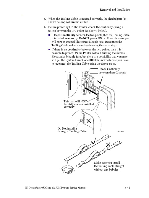
shown below) will not be visible.4.Before powering ON the Printer, check the continuity (using atester) between the two points (as shown below).n If there is continuity between the two points, then the Trailing Cable is installed incorrectly. Do NOT power ON the Printer because you will burn an internal Electronics Module fuse. Disconnect theTrailing Cable and reconnect again using the above steps.n If there is no continuity between the two points, then it is possible to power ON the Printer without burning the internalElectronics Module fuse, but there is a possibility that you maystill get the System Error Code 0B0006, in which case you haveto reconnect the Trailing Cable using the above steps.C607440shown below) will not be visible.4.Before powering ON the Printer, check the continuity (using atester) between the two points (as shown below).n If there is continuity between the two points, then the Trailing Cable is installed incorrectly. Do NOT power ON the Printer because you will burn an internal Electronics Module fuse. Disconnect theTrailing Cable and reconnect again using the above steps.n If there is no continuity between the two points, then it is possible to power ON the Printer without burning the internalElectronics Module fuse, but there is a possibility that you maystill get the System Error Code 0B0006, in which case you haveto reconnect the Trailing Cable using the above steps.C607440。
HP Engage One 10t 维护与服务指南说明书

1 Getting started
Read this chapter to learn about safety information and where to find additional HP resources.
Important safety information
Carefully read the cautions and notes within this document to minimize the risk of personal injury to service personnel. The cautions and notes are not exhaustive. Proper service methods are important to the safe, reliable operation of equipment. Improper service methods can damage equipment. The service procedures recommended and described in this service manual provide effective methods of performing service operations. Service engineers should have prior repair knowledge and experience as well as appropriate training for the product before performing service procedures.
Table of Contents
1 Getting started ..............................................................................................................................................................1 Important safety information..................................................................................................................................1 Important service information and precautions ......................................................................................................1 RoHS (2002/95/EC) requirements............................................................................................................................2 General descriptions ...............................................................................................................................................2 Firmware updates ...................................................................................................................................................2 Before returning the repaired product to the customer.........................................................................................2
- 1、下载文档前请自行甄别文档内容的完整性,平台不提供额外的编辑、内容补充、找答案等附加服务。
- 2、"仅部分预览"的文档,不可在线预览部分如存在完整性等问题,可反馈申请退款(可完整预览的文档不适用该条件!)。
- 3、如文档侵犯您的权益,请联系客服反馈,我们会尽快为您处理(人工客服工作时间:9:00-18:30)。
HP 维修技术手册
HP 维修技术手册
本手册提供了HP产品维修的详细指南和操作步骤。
请在进行维
修前仔细阅读本手册,并按照指示进行操作。
本手册包括以下章节:
1、安全须知
1.1 个人安全
1.2 电器安全
1.3 静电放电防护
1.4 使用正确的工具和设备
2、产品维修流程
2.1 故障诊断
2.2 维修策略
2.3 零件替换
2.4 维修记录
2.5 测试和验证
3、常见问题和解决方案
3.1 电源问题
3.2 显示问题
3.3 声音问题
3.4 硬件问题
3.5 软件问题
4、维修工具和设备
4.1 常用工具
4.2 测试设备
4.3 清洁工具
4.4 备件管理
5、产品维护和保养
5.1 清洁指南
5.2 维护计划
5.3 常见问题预防措施
6、故障代码和错误消息 6.1 故障代码表
6.2 错误消息解决方案
7、常见法律名词及注释
7.1 法律名词解释
7.2 法律名词应用场景
7.3 法律名词案例分析
本文档涉及附件:
附件一、产品维修流程图
附件二、常见问题解决方案手册
附件三、维修工具清单
附件四、法律名词解释词典
本文所涉及的法律名词及注释:
1、版权:指作者对其原创作品享有的法律保护权益。
2、商标:指用于区分商品或服务来源的标识,受商标法保护。
3、专利:指对新发明、新设计或新的实用技术的保护权,以阻
止他人在一定时间内制造、使用和销售该技术。
4、保密协议:指在信息交流过程中确保信息保密的合同或协议。
5、侵权:指未经授权使用他人知识产权的行为,侵害他人权益。