欧姆龙血压计9020血压计通信协议(中文)
欧姆龙PLC通信协议

欧姆龙PLC通信协议参考:W342--SYSMAC CS/CJ Series Communications Commands欧姆龙通信命令可分为两类:1:C-mode commands只可通过串口通讯2:FINS commands既可通过串口通讯也可通过各类网络通信(适应性较强)=============================================================================== 下面只讲FINS命令一、命令发送:FINS直连发送命令如下:FINS command code见下表命令后面紧跟着就是内存区域寻址,见下表Command Code 后面紧跟着需要访问的地址,地址可分为按字地址或按位地址,取决于你需要访的的是字还是某一位。
由紧跟着Command Code后面的那个字节(I/O memory area designation)区分是读取字还是读取位,还是写入字或写入位,具体定义见下表:按字地址:选取表中Data Type列中为Word的命令(命令在Memory area code内)按字地址的三个地址位中,只使用前两个,最后一个字节为Ascii码”00”,其后跟两个字节为需要传输的数据量,然后紧跟着就是传输的数据,数据高位在前低位在后。
例如从H12开始读取7个字的数据,命令为:0101 B2 001200 0007例如将W3、W4、W5分别置数据1234、ABCD、7890,命令为:0102 B1 000300 0003 1234ABCD7890按位地址:选取表中Data Type列中为Bit的命令(命令在Memory area code内)按位地址的三个地址位中,前两个指示位所在的字,最后一个字节指示位在字中的位置(0~15),其后跟两个字节为需要传输的数据量,然后紧跟着就是传输的数据,每一位的值用一个字节的数据代替,当寻址的位为0时用ascii码“0”代替,当寻址的位为1时用ascii 码“1”代替。
关于OMRON CIP通信的编程

关于OMRON CIP通信的编程CLASS通信编程总结注:1、本手册不适用于标准APP的开发,只能作为编程方法使用参考。
2、本手册面向有需求的编程爱好者。
3、本手册主要讲解C#的编程方法。
4、查看本手册时,默认使用者有一定的C#开发经验,基础不进行讲解。
Yanhobey制作老婆给的零花钱得存着…目录目录......................................................................................................................................................... - 1 -图表目录................................................................................................................................................ - 4 -前言......................................................................................................................................................... - 5 -编程注意事项....................................................................................................................................... - 6 -第一部分、SYSMAC Gateway介绍.............................................................................................. - 7 -1、SYSMAC Gateway五大功能:............................................................................. - 7 -1.1 Message通信(显式*)功能 ..................................................................................... - 7 -1.2 周期通信(隐式*)功能................................................................................................. - 7 -1.3标签............................................................................................................................... - 7 -1.4应用程序开发 ............................................................................................................ - 7 -1.5与FINS通信共存...................................................................................................... - 7 -2、SYSMAC Gateway相关信息................................................................................. - 8 -2.1Sysmac Gateway产品配置图............................................................................... - 8 -2.2Sysmac Gateway Console主面板介绍.............................................................. - 9 -3、Sysmac Gateway使用手册链接....................................................................................... - 9 -3.1、安装Sysmac Gateway后的路径................................................................................ - 9 -3.2、本手册路径........................................................................................................................ - 9 -3.3、CX-Compolet手册......................................................................................................... - 9 -第二部分、动态链接库介绍......................................................................................................... - 10 -1、Sysmac Gateway安装目录.............................................................................................. - 10 -2、CX-Compolet安装目录 ................................................................................................... - 10 -3、动态链接库目录...................................................................................................... - 10 -4、示例程序目录 .......................................................................................................... - 10 -4.1所有sample程序,用户可按照需求打开:........................................................... - 10 -4.2常用CIP通信目录,目录中包含所有CIP通信程序示例:.................... - 10 -4.3 Class3(CIPCompolet)通信示例路径.................................................................. - 10 -4.4 Class1(VariableCompolet)通信示例路径 ................................................. - 10 -4.5CIPCore服务打开示例路径................................................................................ - 10 -4.6EIP PORT口打开示例路径 .................................................................................. - 11 -第三部分、CIPCore服务启动编程............................................................................................. - 12 -1、SysmacGatewayCompolet.dll库文件 .............................................................. - 12 -2、SysmacGatewayCompolet完整使用方法Sample程序和手册............... - 12 -2.1Sample程序参考.................................................................................................... - 12 -2.2使用手册 ................................................................................................................... - 12 -3、编程方法讲解 .......................................................................................................... - 13 -3.1引用动态链接库...................................................................................................... - 13 -3.2命名空间 ................................................................................................................... - 13 -3.3实例化变量............................................................................................................... - 13 -3.4使用方法介绍 .......................................................................................................... - 13 -3.5代码解释 ................................................................................................................... - 14 -第四部分、Port口启动和停止编程........................................................................................... - 15 -1、CIPPortCompolet.dll库文件............................................................................... - 15 -2、CIPPortCompolet完整使用方法程序和手册................................................ - 15 -2.1Sample程序............................................................................................................. - 15 -2.2使用手册 ................................................................................................................... - 15 -3、编程方法讲解 .......................................................................................................... - 16 -3.1引用动态链接库...................................................................................................... - 16 -3.2命名空间 ................................................................................................................... - 16 -3.3实例化变量............................................................................................................... - 16 -3.4使用方法介绍 .......................................................................................................... - 16 -3.5代码解释 ................................................................................................................... - 16 -第五部分、CLASS3通信编程(CIPCompolet).................................................................... - 17 -1、CIPCompolet.DLL库文件..................................................................................... - 17 -2、CIPCompolet完整使用方法程序和手册 ........................................................ - 17 -2.1 Sample程序.................................................................................................................... - 17 -2.2 使用手册.......................................................................................................................... - 17 -3、编程方法讲解 .......................................................................................................... - 18 -3.1 引用动态链接库............................................................................................................... - 18 -3.2 命名空间 ............................................................................................................................ - 18 -3.3 实例化变量........................................................................................................................ - 18 -3.4 使用方法介绍................................................................................................................... - 18 -第六部分、CLASS1编程(VariableCompolet)................................................................... - 19 -1、网络架构 ................................................................................................................... - 19 -2、VariableCompolet.DLL库文件........................................................................... - 19 -2.1 Sample程序....................................................................................................................... - 19 -2.2 使用手册 ............................................................................................................................ - 19 -3、编程方法讲解 .......................................................................................................... - 20 -3.1 引用动态链接库............................................................................................................... - 20 -3.2 命名空间 ............................................................................................................................ - 20 -3.3 实例化变量........................................................................................................................ - 20 -3.4 使用方法介绍................................................................................................................... - 20 -结论....................................................................................................................................................... - 21 -图表目录图1 Class1和Class3架构图 .......................................................................................................... - 5 -错误线程编辑图.................................................................................................................................. - 6 -正确线程编辑图.................................................................................................................................. - 6 -图3 SGW操作面板图....................................................................................................................... - 9 -图4 Sysmac Gateway Service使用方法手册图...................................................................... - 12 -图5程序引用图............................................................................................................................... - 13 -图6 PortCompolet操作手册........................................................................................................ - 15 -图7 CIPCompolet操作手册......................................................................................................... - 17 -图8 VariableCompolet通信示意图........................................................................................... - 19 -图9 VariableCompolet操作手册................................................................................................ - 20 -前言此文档的所有内容都是基于PC上安装了OMRON SYSMAC Gateway的前提下进行的描述。
电子血压计校准方法欧姆龙

福禄克校验方法检测类型:全自动电子血压计:9020/9021血压计,曲线设定值-10%,203血压计,曲线设定值-4%。
半自动电子血压计:907/1300/7071血压计,曲线设定值-4%。
1.检测器材:9020/9021血压计、907/1300/7071血压计、袖套、电源线、福禄克检测仪、三通管(三根直流管、一个三通)、检测模块(5个拼装模块)。
2.检测目的:检测血压计的稳定性和准确度。
3.9020/9021/203血压计检测方法:动态测量法:1.将检测模块(一般为四个组合模块)放入袖筒里面;2.用三通管将9020/9021/203血压计(接口处于本体背面盖,扭开螺丝, 9020/9021连接300气孔)与福禄克检测仪连接;3.接通福禄克和血压计电源,福禄克按到NIBP检测模式,调整到常规检测血压值(180/120、120/80、90/60毫米汞柱,对应心率大概为80/分、70/分、60/分)进行测定,曲线设定值为-10%(203血压计曲线设定值为0%),然后血压计按开始键开始检测。
静态测量法:1.将检测模块放入袖筒里面;2. 用三通管将9020/9021/203血压计(接口处于本体背面盖,扭开螺丝,9020/9021连接300气孔)与福禄克检测仪连接;3. 9020/9021本体背面的模式开关设定在“2”的刻度位置(正常设定“4”的刻度);4.按住模式开关的同时打开电源开关ON(203血压计同时按住模式和停止键),此时HBP-9020/9021显示屏显示的代码为tES_1,203血压计显示屏显示的代码为t_0,此为检测模式;5.在检测模式下,HBP-9020选择[tES_13]、HBP-9021选择[tES_14],按上、下按钮加减数值(203血压计不用调整数值),再按下开始/停止按钮,自动卷紧模拟手臂,等待几秒后,舒张压和收缩压均为0,然后开始测量。
4.907/1300/7071血压计检测方法:动态测量法:1.用袖套绑住检测模块(一般为三个组合模块);2.用三通管连接907/1300/7071血压计、袖套和福禄克检测仪(此连接无特定要求);3.接通电源,福禄克调到NIBP模式,调整到常规检测血压值(180/120、120/80、90/60毫米汞柱,对应心率大概为80/分、70/分、60/分)进行测定,曲线设定值为-4%,然后血压计按开始键开始检测。
欧姆龙电子血压计压力精度检测方法
电源开关 ON
OFF
检定模式按钮 1234
P R I 打印选择N按钮
ON OFF
T O N
SD 卡插口
RS232C
测定压力精度的检定测试(自动卷紧)
【必要材料】 周长36cm的圆柱体、压力计(水银计)、Y 字管、橡皮球、空气插头
【规格】 器差 ±6mmHg 以内
【检测手续】 (1)将周长36cm的圆柱体放入臂筒部位。
(自动卷紧)]用▲・▼按钮选定、再按下开始/停止按钮。自动卷紧模拟手臂。
(5)关闭橡皮球的空气开放口、依次设定 280、140mmHg 等压力值、依次记录被检测机器的压
力值、确认是否满足规格的要求。
HBP-9020 测定压力显示
HBP-9021 测定压力显示
测定压力精度检定测试(自动卷紧)
(6)按下开始/停止按钮。 臂带放气、返回检测模式。
周长 36cm 圆柱体
(2)将“300空气插孔”与压力计(水银计)、橡皮球用Y字管、和空气插头如图连接。 请确认打开橡皮球的空气开放口。
300 空气插孔
空气插头
压力计(水银表)
(3)被检查机器请调整到检测模式。
*检测模式请参见上页准备。
(4)在检测模式下、HBP-9020 选择[tES_13]、HBP-9021 选择[14. 测定压力精度的检定测试
测定压力值
90
mmHg
90
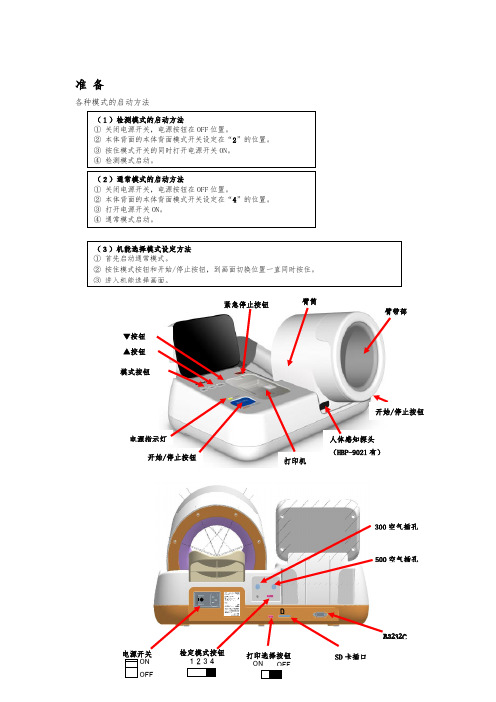
准备
各种模式的启动方法
(1)检测模式的启动方法 ① 关闭电源开关,电源按钮在 OFF 位置。 ② 本体背面的本体背面模式开关设定在“2”的位置。 ③ 按住模式开关的同时打开电源开关 ON。 ④ 检测模式启动。
(2)通常模式的启动方法 ① 关闭电源开关,电源按钮在 OFF 位置。 ② 本体背面的本体背面模式开关设定在“4”的位置。 ③ 打开电源机能选择模式设定方法 ① 首先启动通常模式。 ② 按住模式按钮和开始/停止按钮,到画面切换位置一直同时按住。
欧姆龙plc通讯协议
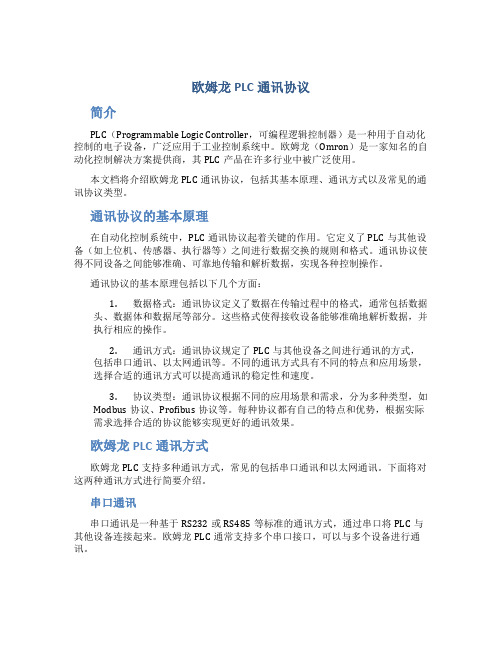
欧姆龙PLC通讯协议简介PLC(Programmable Logic Controller,可编程逻辑控制器)是一种用于自动化控制的电子设备,广泛应用于工业控制系统中。
欧姆龙(Omron)是一家知名的自动化控制解决方案提供商,其PLC产品在许多行业中被广泛使用。
本文档将介绍欧姆龙PLC通讯协议,包括其基本原理、通讯方式以及常见的通讯协议类型。
通讯协议的基本原理在自动化控制系统中,PLC通讯协议起着关键的作用。
它定义了PLC与其他设备(如上位机、传感器、执行器等)之间进行数据交换的规则和格式。
通讯协议使得不同设备之间能够准确、可靠地传输和解析数据,实现各种控制操作。
通讯协议的基本原理包括以下几个方面:1.数据格式:通讯协议定义了数据在传输过程中的格式,通常包括数据头、数据体和数据尾等部分。
这些格式使得接收设备能够准确地解析数据,并执行相应的操作。
2.通讯方式:通讯协议规定了PLC与其他设备之间进行通讯的方式,包括串口通讯、以太网通讯等。
不同的通讯方式具有不同的特点和应用场景,选择合适的通讯方式可以提高通讯的稳定性和速度。
3.协议类型:通讯协议根据不同的应用场景和需求,分为多种类型,如Modbus协议、Profibus协议等。
每种协议都有自己的特点和优势,根据实际需求选择合适的协议能够实现更好的通讯效果。
欧姆龙PLC通讯方式欧姆龙PLC支持多种通讯方式,常见的包括串口通讯和以太网通讯。
下面将对这两种通讯方式进行简要介绍。
串口通讯串口通讯是一种基于RS232或RS485等标准的通讯方式,通过串口将PLC与其他设备连接起来。
欧姆龙PLC通常支持多个串口接口,可以与多个设备进行通讯。
串口通讯的优点是成本较低,适用于小规模的控制系统。
然而,由于串口通讯的传输速率较低,其通讯距离有限,且易受干扰。
因此,在一些大规模、复杂的控制系统中,串口通讯的应用相对较少。
以太网通讯以太网通讯是一种基于以太网协议的通讯方式,通过以太网将PLC与其他设备连接起来。
欧姆龙通讯协议种类

欧姆龙通讯协议种类欧姆龙通讯协议是指用于欧姆龙公司产品之间进行数据通信的一种协议。
欧姆龙作为一家全球领先的工业自动化解决方案提供商,其产品广泛应用于工业控制、电子设备、医疗设备等领域。
为了实现这些产品之间的数据交互,欧姆龙推出了多种通讯协议,以下将介绍其中一些常见的种类。
1. 欧姆龙Host Link协议欧姆龙Host Link协议是一种用于欧姆龙PLC(可编程逻辑控制器)和上位机之间的数据通信协议。
通过该协议,用户可以在上位机上监控和控制PLC的运行状态,实现数据的读取和写入。
该协议具有简单、高效的特点,广泛应用于工业自动化领域。
2. 欧姆龙FINS协议欧姆龙FINS协议是一种用于欧姆龙各种设备之间进行数据通信的协议。
它支持多种通信方式,包括串口、以太网等。
通过该协议,用户可以实现不同设备之间的数据传输和控制命令的交互。
FINS协议具有高速、可靠的特点,被广泛应用于工业自动化控制系统。
3. 欧姆龙Ethernet/IP协议欧姆龙Ethernet/IP协议是一种基于以太网的工业自动化通信协议。
它可以实现不同设备之间的数据交互和控制命令的传输。
Ethernet/IP协议具有高速、可靠的特点,广泛应用于工业自动化网络中。
4. 欧姆龙Modbus协议欧姆龙Modbus协议是一种用于欧姆龙设备和其他设备之间进行数据通信的协议。
它是一种开放的通信协议,可以与其他厂家的设备进行兼容。
通过Modbus协议,用户可以实现设备之间的数据交互和控制命令的传输。
以上是一些常见的欧姆龙通讯协议种类,它们在工业自动化领域起到了重要的作用。
通过这些协议,不同设备之间可以实现数据的传输和控制命令的交互,提高了生产效率和自动化水平。
欧姆龙作为工业自动化领域的领先企业,不断推出新的通讯协议,以满足不同应用场景的需求。
欧姆龙 健太郎 医用电子血压计 说明书
医用电子血压计带自动臂套及发音功能的全自动血压计为了使您能够正确地使用本产品,使用前请务必阅读本使用说明书。
阅读后请放在该血压计的附近妥善保管。
使用说明书进口产品标准号:YZB/JAP 0674-2007国食药监械(进)字2007第2211424号计量器具形式批准证书号:2007-F244WPP纸注意事项原则•根据著作权法,未经允许禁止转载本说明书中的部分或全部内容。
•本说明书的内容若有变更,恕不另行通知。
•本说明书在编写时虽已极力完善,但万一有不完善的地方或错误之处,请与本公司联系。
•如有缺页或错页由本公司负责更换。
-1-使用前非常感谢购买使用欧姆龙健康医疗事业株式会社生产的医用电子血压计“ ADVANCE ”BP-203RVⅢ。
本产品的功能因机种的不同而不同。
本书中的照片、插图等采用的是C 型血压计。
■BP-203 RV Ⅲ Type C (带打印机)■ BP-203 RV Ⅲ Type D(不带打印机)希望您能够仔细地阅读本说明书,在充分了解本机的使用方法、注意事项、性能及使用范围的基础上安全使用本血压计。
另外,阅读后请妥善保管,以便他人能随时阅读。
重要为了使您能够正确地使用本产品,使用前请务必阅读本说明书。
阅读后,请放在该血压计的附近妥善保管。
关于安全标识为了能安全、正确地使用本产品,防止人身伤害和财产损失事故的发生,在本使用说明书及产品上用图形符号做出了标识。
标识及其含义如下,请充分理解标识的内容之后,再阅读说明书正文。
[危险]表示如果不按照要求进行操作,会直接导致死亡或重伤。
[警告]表示如果不按照要求进行操作,有可能导致死亡或重伤。
[注意]表示如果不按照要求进行操作,有可能导致轻伤或中等程度的人身伤害,或损坏设备。
△符号表示有提醒注意(含警告)的事项(左图表示注意触电)。
符号表示禁止该行为。
在图中或图的旁边写有具体的禁止内容(左图表示禁止拆卸)。
●符号表示必须强制执行的内容。
(在图中或图的旁边写有具体的指示内容(左图表示把电源插头从插座上拔下)。
HBP-9020欧姆龙电子血压计技术参数
测量范围:压力:0-299mmHg(0~39.9kPa),脉搏数:40次/分-180次/分
1.8
精确度:压力:+3mmHg(+0.4kPa)以内,脉搏数:+2%以内
1.9
高血压自动判定功能:可根据测量值自动判定高血压程度并在屏幕能显示提醒,给予用户及时的健康提示
1.10
慢病宣教播放功能:可插SD卡,根据各科室个性化需求下载宣教知识并播放
血压仪技术参数
序号
技术要求
1.1
测量内容:收缩压、舒张压、脉搏,数字式LCD显示
★1.2
测量原理:示波法
1.3
测量位置:左右手都可测量
1.4
语音提示功能:测量姿势正确提示功能、测量过程提示、测量结果播报
1.5
抗菌设计:机身及袖套全部采用抗菌材料并提供证明文件
★1.6
软件著作权:提供血压测量信息管理系统软件
1.28
安全分类:1组、B类设备
1.29
宁波本地三乙级以上医院用户≥5家,并提供证明文件
1.11
舒缓音乐播放功能:可选择音乐播放功能,按测量键后自动播放音乐,舒缓患者紧张心情
1.12ห้องสมุดไป่ตู้
人体感应功能:测量结束后一定时间可切换至待机模式,达到节能效果;当感应到人,自动转换测量模式
★1.13
肘部位置传感器:有,测量时当肘部放置传感器开关时,屏幕会及时显示手臂姿势错误或正确的提示
1.14
臂筒角度调节功能:具有上向臂筒角度调节,方便受测者手臂姿势与高度的调整,确保测量数据更加精准
1.22
打印装置:全中文热敏打印、自动裁纸、多种模式可选 ,用户信息可编辑打印
1.23
压力单位:mmHg 和 Kpa 两种模式互选
Omron PLC NX102-9020与V430代码阅读器的Sysmac设置及EIP通信说明书
PurposeThe purpose of this document is to describe the setup configurations required for addingV430 code reader to a PLC project using Sysmac and Omron PLC. This tutorial document uses Omron PLC model NX102-9020, but is useful also for NJ PLC. The intention is to target beginners with Sysmac and with V430. Therefore, extra details are explained with a walkthrough the steps to bring up a working setup. In this document there are practical examples of read / write data between the PLC and the reader over EIP.Table of contentPurpose (1)Table of content (2)Create new project (3)Adding the PLC controller to the project (4)Verify correct network settings (4)Reader configuration (5)Install EDS file (7)Create new EIP connection for the reader (8)Install Sysmac library with data definitions (10)Input / Output assembly (11)Using Big Input Assembly (11)Create global variables (13)Transfer the project to the PLC (15)Reading data from reader to PLC (18)Example 1 – read decoded text (19)Example 2 - Get status of reader’s digital outputs (20)Example 3 - Get status of external trigger input (20)Example 4 – Read the current value of the available counters (21)Sending data from PLC to reader (22)Example 1 - Trigger the reader from the PLC over EIP (23)Example 2 - Disable scanning (put reader to offline) over EIP (23)Sending match data to the reader - Explicit messages (24)Explicit messages – Overview (24)Example 3 – sending matchdata K command using explicit messages (26)Assembly info (26)Send message structure (26)Receive message structure (26)Ladder program implementation (27)Explicit commands – Common errors (31)Testing the implementation (32)Create new project1. Start-up Sysmac software and create a new project, providing a new name to the project.Adding the PLC controller to the projectAdd the PLC and the external modules like power supply and I/O extensions into the project, by finding them first in the toolbox search on the right side. Then drag and drop into the PLC rack on the left.Verify correct network settingsNext stage is to configure the network settings on PLC, PC and reader to be on the same network. For example, in our project the network settings are below:PLC: 192.168.188.5, 255.255.0.0PC: 192.168.188.20, 255.255.0.0V430 : 192.168.188.2, 255.255.0.0Reader configurationOn the reader side, we need to enable EIP communication, then reboot. Enable EIP from Weblink (verify that byte swapping is disabled).After enabling EIP, save settings to flash and reboot the device:To verify the EIP enable status parameter in the flash memory, it is possible to read out the settings via telnet using the following command: BP_DumpAll*If the parameter is still not changed in the flash memory, there is another way to change the EIP enable parameter, using the following telnet command: BP_UpdateEIPEnable(1)*A third way is sending the K-command <K129,1> over TCP or telnet connection (port 2001/2003). Don’t forget to reboot the device, so the new settings will take effect.Install EDS fileIn Sysmac menu, select Tools->EIP connection settings, In the toolbox right click->display EDS library. If V430 EDS is installed already, it will appear there. If not, press install button and browse to the EDS file saved locally on the PC. The EDS file can be downloaded from Omron GTKS website. EDS file used for this tutorial:V430(32-9000097-01).edsIn EIP Device list window, right click on the PLC, then Edit:Then in the toolbox on the right side, right click in the window, then ‘Display EDS Library’.Then click ‘Install’ button and browse to the EDS file on the PC.After a successful installation of the EDS file, the V430 appears in the installed library:Create new EIP connection for the readerAfter EDS file is installed, i n toolbox on the right side, Click ‘+’ button to add a device, give IP settings and select V430 from the list. Then V430 will be available for selection as a new EIP connection.Open window Built-in EIP port settings in connection view, and add new connection:Install Sysmac library with data definitionsImport the provided library by Omron which includes data structures for V430 memory mapping. To install the library file, In the menu select Project->Library->Show References, then add the library by clicking on the + button, browsing to the provided .slr file in the PC.Then we have the required data types and structures pre-defined for the V430 inside the library:Input / Output assemblyIn this stage, before we add connection variables, we need to select the desired input / output assemblies to work with. There are several options to choose from. Please refer to the documentation for full details. Here we will give example of using Big Input Assembly (#101) and Legacy output assembly (#198).Using Big Input AssemblyWhen more info is required to be read from the reader, like real time reader status for example, which is required for proper communication handshake between reader and PLC, we will need to use the Big input assembly (Assembly 101, which has 176 byte in total):For more info about the input assembly, please refer to the documentation of ID-40 reader. In the following pages we bring some examples of reading useful input data from the reader. Let’s look first at the documentation to see what info we can get from the device:CountersSeveral counters are available, which can be very useful in run time. Triggers counter, Read Cycle counter, No R eads counter and more…Decode dataJust like in the Small Input Assembly, here we also have the decode string with the length info of the string in the preceding 4 bytes.Required setup in SysmacTo use the Big Input structure to get data from the reader, we need to define the correct input variable in Sysmac (step by step instructions are described earlier in this document). After the setup, verify that the displayed structure size in bytes is correct, according to the documentation. Otherwise the project will not be downloaded to the PLC properly.Create global variablesIn the Sysmac explorer on the left side, under global variables create 2 new variables, one for input and one for output:Now make them published, so we can register them later successfully:Under task settings -> VAR tab, add the two variables we have just created, using ‘+’ button. Select them from the options:Go to built-in port settings and click the button register all, to register all tags:(To reach this window, first select Tools->EIP settings, then right mouse on the PLC and click Edit. Then click on the button 10)After a successful registration the IN / OUT tags should look like this:Then in connection tab add the target variable and originator to have the following final settings:*Note that the EIP refresh rate (RPI) can be max 10ms. It can be faster, but if slower it can cause issues with sensing status signals from the reader, resulting in missing decode results.The required settings and configurations for the PLC project are completed. Now the project is ready to compile and download to the PLC, then we can test operations like read / write data between the PLC and the reader.Transfer the project to the PLCBuild the project and verify no errors:Verify no errors in output window:Go to online mode with the PLC. If needed, use the connection wizard:When online connection with the PLC is OK, transfer the project to the PLC:Verify that PLC is in run mode and without errors (All Green LEDs):*Note that you need to enable the transfer of Network settings, as we changed those for creating the EIP connection properly. (It is disabled by default). See screenshot below.When PLC is set back to run mode, the EIP communication is started. Verify the connection status by monitoring the PLC status: right click on the PLC, then select ‘monitor’:See below example for a typical monitor window of a correct connection status and tag status:Reading data from reader to PLCTo see the incoming data from the reader to the PLC use watch window, adding the relevant data structures (ID_IN and ID_OUT).Note that in this tutorial we are using Big Input assembly which has extended amount of input data, which gives many options for reading useful status data from the reader.The incoming data from the reader to the PLC can be found under ID_IN structure:The outgoing data from PLC to reader, can be found under ID_OUT structure:Example 1 – read decoded textTo find the decoded text after a good read or no_read, we need to view the decode data string array as shown below. So verify that there is a symbol in front of the reader, trigger once and view the results.For better readability we change the display format column to show ASCII format:Just for a cross-check, view in parallel the good read symbol in Weblink:Example 2 - Get status of reader’s digital outputsWe trigger a Good Read to activate output 1, after configuring it to Latch on a good read in Weblink. After the next trigger, verify that the relevant output is activated:In the watch window, looking at bit 0 of external output status memory location, we will find that this bit is TRUE:Example 3 - Get status of external trigger inputEach time we trigger the reader from external source (for example Trigger sensor), we can monitor the status of that input signal in bit 0 of External Input Status register:Example 4 – Read the current value of the available countersA good monitoring method of the system’s performance is to monitor different counters and compare the values. Let’s look at the counter values in our setup. In the watch window we extend the view of structure ID_IN to view all counters listed. For better readability we configure the display format column to show number in decimal.In the screenshot below we can see the current values of the counters in our setup. From the numbers we can learn the following:1. The reader received 4 triggers in total2. The reader entered 4 read cycles (it means that there are no missed triggers / overruns)3. Decode counter shows 3 good reads4. No_Read counter shows 1 No_Read eventSending data from PLC to readerFor sending data from PLC to reader, in this example we use the Legacy output assembly:Commands:Using the Command BIT fields we c an control the reader’s status / operation. For example, to trigger the device from the PLC which will be described later in this document as example.The possible BIT Commands are listed below:=>Trigger (bit 0) – triggers the reader once=>Disable scanning (bit 8) – puts the reader to online / offline mode=>New Master (bit 1) – saves a new master on the next good read=>Clear (bit 16) – Clears the results data from the memoryFor detailed description about the functionality below, please refer to the documentation. See below several examples for sending control commands to the reader:Example 1 - Trigger the reader from the PLC over EIPWhen looking at the data structure of the command bit fields, we see that bit 0 is the trigger bit. To trigger the device we need to change this bit from FALSE to TRUE (then back to false):In the watch window, under EIP_OUT -> Commands change bit 0 to TRUE and watch the reader to verify that it was triggered:Example 2 - Disable scanning (put reader to offline) over EIPWe can put the reader to offline / online state using bit 8 of the of the Command BITs register. By default this bit is FALSE and reader online (scanning enabled -> reader reacts to triggers). When the bit is TRUE, it means that the reader is put to offline and scanning is disabled. Triggers are ignored.After forcing this bit to TRUE in watch window, try to trigger the reader and verify that it is not reacting to triggers.Sending match data to the reader - Explicit messagesThe Matchcode feature is commonly used. This feature enables the reader to compare the reading result to a known string (Matchdata) on every trigger and send out a Pass/Fail result. (Please refer to the manual for more details).The preferred way to send a new Match data to the reader is by K command over EIP. It is possible only by using explicit messages. We will give first a quick overview below, then describe a real example on how to implement this in the PLC program.Explicit messages are useful also for other purposes. It enables sending K-commands to the reader. By sending K commands we can change the reader settings on the fly, as well as read various status data from the reader.Explicit messages – OverviewExplicit messaging is sending / receiving data between PLC and reader over TCP/IP communication. Therefore, it is meant for data that is not time critical like the Implicit messaging I/O data. Implicit messaging (which is the cyclic data which goes back and forth between reader and PLC) is sent over UDP packets.Using Explicit messaging the user can send and receive data which is not pre-defined in size and timing like the implicit I/O messaging. For example, the user can send and receive any K commands to and from the reader and request any data from the reader, as well as change reader configuration in run time.To send and receive K Commands to the V430 reader, the assembly below can be used:Serial Command Assembly (Instance Decimal: 69 Hex: 0x45) IN/OUT = PLC ID-40 readerThis assembly is accessible only through explicit messaging, to allow the programmer to use the implicit Input/Output assemblies in parallel with this explicit assembly. In the same project it will be possible to use the Input/Output assemblies for read/write data to/from the reader, as well as use this explicit command assembly to send and receive K commands.See relevant info below, taken from the reader device documentation:(Service code and class are in HEX format).The following table shows which service type is supported by each input / output assembly:Example 3 – sending matchdata K command using explicit messagesThis example was created using PLC NX102-9020 and V430 reader. But the method described below is valid also for NJ PLCs.Assembly infoWe will use the following Assembly info, as taken from the documentation:Service Code = 0x45 (= 69d)Class = 0x68 (= 104d)Instance = 1Attribute = 1Send message structureStructure of the message to send out from the PLC to the reader:For example, the K command <K231?> (requesting matchcode info) has a length of 7 characters. Therefore, the first 4 bytes (command length) will be: 07 00 00 00 (LSB first). Then comes the 7 bytes of the K command itself. The total length of this message will be 11 bytes. 4 bytes of length info and 7 bytes of the command itself.Receive message structureIn case there is a response from the reader to PLC, the structure of the received message is below:For example, the K command <K231?> should receive the following reply from the reader:<K231, 1, 12345678>(matchcode info from the reader).The data length is 17 characters => 17 bytes. So, the first 4 bytes (message length) should be 17 and the next 17 bytes will be the data itself. In total the received message has 17 + 4 = 21 bytes.See below log data from Weblink terminal, where the Matchcode is inquired and the response arrives:Ladder program implementationThe implementation described below shows how to send a single explicit message from NX or NJ PLC, carrying any K command.The main function used here is CIPUCMMSend which is a standard Sysmac function:1. In the first 4 rangs, the data structure RqPath is assigned with correct values using MOVEfunctions:2. In the next rang we define the K command we want to send (send new matchcode data to thereader), then copy the data to the correct place inside ByteArrayToSend. In this example, we need to define a local Array with minimum 19 bytes for sending this message:(4 bytes of length + 17 bytes of the K command itself)So to be on the safe side, we define a bigger array of 51 bytes. The array should be big Enough to contain all the sent data. It can be bigger but not smaller.3. Now copy the K command string into the byte array, leaving the first 4 bytes empty.Note that we send at once two K commands. One to send the new match data and another one to inquire the match data. This way we can verify that the new match data is arrived OK to the reader.In the next rang we extract the command length, then complete our Byte Array with thecommand length info in the first 4 bytes (LSB first):4.5. In the next rang we use the CIPUCMMSend function to actually send the data to the reader:6. When there is a response data sent back from the reader as a reply, we receive it into thearray MyRespArray:After checking that the response data is not empty (MyRespSize > 4 bytes), the data is separated from the length info and provided in a String variable: RespStringSee below the complete list of internal variables used in this example:Explicit commands – Common errorsAfter launching the send function CIPUCMMSend, there are possible errors that can occur. The meaning of the error code can be found in the help (Press F1, then search for the error code).Here are some common errors and the possible root cause:1. Wrong input parameterWhen this error is occurred, it means that one of the input parameters for the send function is out of range or from the wrong type.2. Timeout on sendingWhen this error is occurred, it means that there was no response from the reader on this K command. Some commands produce a response and some commands not. For example, the command of sending new matchcode is not producing a response from the reader. Therefore, we should expect a timeout error on sending.Note that the timeout error happens also when the command is received properly on reader side. So this error should be ignored on PLC side.A good workaround is sending two K commands together. One to send a new match data and one to inquire the saved match data. This way we can also verify that the change is done.Testing the implementation1. In Weblink, verify good read, then enable Matchdata feature and trigger again to verify failure (should fail, as we didn’t send yet the Matchdata).2. Now on PLC side, launch the sending of the K command via explicit, as described above.3. To verify that the correct matchdata is sent OK, trigger again and view the results in Weblink to see if Pass or Fail. Since the inspection is passed, we can conclude that the matchdata is sent OK to the reader (on PLC side it is a good practice to verify the match data change by comparing the new matchcode we sent to the matchcode we receive in the response on our inquiry.。
欧姆龙plc通讯协议
欧姆龙plc通讯协议欧姆龙PLC(Programmable Logic Controller)通信协议是用于PLC与外部设备进行数据传输的规范。
在工业自动化领域中广泛应用的PLC通信协议有很多种,其中欧姆龙PLC通信协议是由日本欧姆龙公司开发的,适用于欧姆龙PLC与其他设备之间的通信。
欧姆龙PLC通信协议分为串行通信和以太网通信两种方式。
串行通信使用RS-232C或RS-485接口进行数据传输,而以太网通信使用乙太网进行数据传输。
两种通信方式各有优劣,可以根据实际需求选择合适的通信方式。
欧姆龙PLC通信协议主要包括通信参数设置、数据传输、数据读写及状态监测等功能。
通信参数设置包括通信端口号、波特率、数据位、校验位、停止位等参数的设置。
数据传输可以通过发送和接收数据帧来实现,数据帧包括起始符、目的地址、源地址、数据长度、校验位等信息。
数据读写可以通过读取和写入寄存器的方式来实现,可以实现对PLC中的输入信号和输出信号的读取和控制。
状态监测功能可以实时监测通信连接状态,包括通信故障、通信超时等状态。
欧姆龙PLC通信协议的优点在于稳定性高、可靠性强、数据传输速度快。
它可以实现PLC与其他设备之间的高效通信,例如与人机界面HMI进行数据交换、与上位机进行数据采集和控制等。
通过欧姆龙PLC通信协议,可以实现对生产过程的监控和控制,提高生产效率和品质。
虽然欧姆龙PLC通信协议在工业自动化领域中得到了广泛应用,但它也存在一些局限性。
例如,通信距离有限,一般不超过几千米;通信速度受限,无法满足高速数据传输的需求;另外,由于欧姆龙PLC通信协议是专有协议,与其他厂家的设备之间的通信可能存在一定的兼容性问题。
总的来说,欧姆龙PLC通信协议是工业自动化领域中非常重要的一种通信协议,它为PLC与外部设备之间的数据传输提供了可靠的规范。
通过合理的设置通信参数和灵活的数据读写方式,可以实现PLC与其他设备之间的高效通信,提高生产过程的自动化水平。
- 1、下载文档前请自行甄别文档内容的完整性,平台不提供额外的编辑、内容补充、找答案等附加服务。
- 2、"仅部分预览"的文档,不可在线预览部分如存在完整性等问题,可反馈申请退款(可完整预览的文档不适用该条件!)。
- 3、如文档侵犯您的权益,请联系客服反馈,我们会尽快为您处理(人工客服工作时间:9:00-18:30)。
[STX] 有效负荷部
[ETX]
有效负荷部内最后输入数据是 ASCII 码,数值数据的 16 进制的表示的各位用 ASCII 码,从复数位中完成的 是从上位开始按序输入数据包中。
THDK-A8F40081
資料 No.HDV-BP-092385 (5/9)
DATA
DIA CR PR CR
16 近制 ASCII 位数 3 位
3位
RVⅡ设定
BYTE
1~2 3~10
11 12~13 14 15~16 17 18~19 20 21~22 23 24~25
DATA
'ID' '99999999' 'B' 年(YY) '/' 月(MM) '/' 日(DD) '/' 时 ':' 分
THDK-A8F40081
資料 No.HDV-BP-092385 (8/9)
3.2 通信顺序 3.2.1 通常形式时:
血压计的正确操作时的通信顺序如下规定。 1) 血压测定(正常测定时) 根据 Start/Stop 的信号开始测定。测定结束时,主 CPU 向 PC 发送测定的结果,以 1 次的血压测定为结束的形式。
2位
BYTE
38~39 40 41~43 44 45~47 48 49~51 52 53~55 34
57
DATA
分 ',' SYS ',' MAP ',' DIA ',' PR ',' 体动回数
16 近制 ASCII 位数 2 位
3位
3位
3位
3位
1位
10 关键设定
BYTE
1~2 11
3~22
23 24~27 28 29~30 31 32~33 34 35~36 37
THDK-A8F40081
資料 No.HDV-BP-092385 (3/9)
1. 序言
1.1 目的 以 HBP-9021/ 9020 的开发使用说明书为基础、明确主 CPU-PC 间的通信使用说明为目的。
1.2 适用 适用于 HBP-9021/9020。
2. 连接构成
PC 和主 CPU 连接时、使用外部通信端子(RS232C)。 PC 和主 CPU 在 UART 的通信线(TxD,RxD)上连接。
DATA
分 ',' SYS ',' MAP ',' DIA ',' PR ',' 体动回数 CR SPSPSP
16 近制 ASCII 位数 2 位
3位
3位
3位
3位
1位
3位
BYTE
62 63~65
DATA
',' SPSPSP
16 近制 ASCII 位数
3位
※表中的 SP 是 SPACE 的意思,ASCII 码是 0x20。
資料 No.HDV-BP-092385 (1/9)
HBP-9020/9021 外部通信式样书
第 1.0 版
THDK-A8F40081
【目录】
資料 No.HDV-BP-092385 (2/9)
1. 序言 ........................................................................ 3 1.1 目的 .......................................................................... 3 1.2 适用 .......................................................................... 3
※无论何时,实施臂袋压力的定期送信
PC
开始/停止 按下 SW 测定开始要求
主 CPU
血压测定 CPU
开始/停止按下 SW 测定开始要求的命令成为某种触 发
Start/Stop 信号发出
血压测定
血压测定结果通知 ・ 测定时间 ・ SYS,DIA,PR値 ・ (平均值血压。体动回数)
测定结果通知 ・ SYS,DIA,PR值 ・ 平均血压值 ・ 体动回数
3.1.3 数据包受信判定 最低判定数:当 1 字节以上的受信时,进行数据包的内容解析。 若有符合的指令/回答,要有相对应的处理。若没有时,储存受信的内容。 最后从受信的时间到未受信的状态经过了 300ms 的情况,或是,储存数据量≧384byte 的情况,储存的内容会 清空。
3.1.4 有效指令 根据通信协议,因为可能实行的机能的不同,受理的指令也不同。
2. 连接构成 .................................................................... 3 3. 通信协议 .................................................................... 4
表中的 CR 是 SPACE 的意思,ASCII 码是 0x0d。
d.测定错误时:仅在 RVⅡ设定的情况下送信
BYTE
1~2 3~10
11 12~13 14 15~16 17 18~19 20 21~22 23 24~25
DATA
'ID' ID 番号 8 位 'B' 年 '/' 月 '/' 日 '/' 时 ':' 分
RVⅢ设定
BYTE
1~2 11
3~22
23 24~27 28 29~30 31 32~33 34 35~36 37
DATA
'bp' ',' '999...999' ',' 年(YYYY) '/' 月(MM) '/' 日(DD) ',' 时 ':'
16 近制 ASCII 位数
20 位'9'
4位
2位
2位
3.1 通信的构成 .................................................................... 4 3.2 通信顺序 ...................................................................... 8
BYTE 1 DATA 'B'
・ f.时针设定变更要求
时刻设定的命令
BYTE
1
2~3
4~5 6~7 8~9 10~11
DATA
'C' 年(西历下 2 位) 月 日 时
分
16 近制 ASCII 位数
2位
2位 2位 2位 2位
< 主 CPU → PC >
・ 血压测定结果通知 c.正常测定时:
RVⅠ设定
BYTE
1~8
9 10~13 14 15~16 17 18~19 20 21~28 29 30~32 33
DATA
'MMBP203' CR 年(YYYY) '.' 月(MM) '.' 日(DD) CR '99999999' CR SYS CR
16 近制 ASCII 位数
4位
2位
2位
3位
BYTE
34~36 37 38~40 41
PC 发出的命令
可能受理的时间
测定开始要求
待机状态
测定中断要求的处理 测定时
结果再发送要求的受理 装入电源后至少一次正常测定结束时的待机状态
时钟设定变更的受理 待机状态
非受理时间的受信,或者是未定义的命令的受信的情况下有以下的应答出现。 RVⅡ的通信设定:向 PC 送信「传送结束要求」 RVⅡ以外的通信设定:没有任何应答PC主T来自DCPURxD
THDK-A8F40081
3. 通信协议
3.1 通信的构成 3.1.1 通信规格 同 PC 的连接,可以使用 RS-232C。
有关通信协议的概要如下所示。 调步同期式连续通信,全二重 TTL 水平
外 部 输 入 输 出 每秒位数
数据位
力
转换设定
RV
2400bps
7bit
RV2
16 近制 ASCII 位数
8 位’9’
2位
2位
2位
2位
2位
BYTE
26 27~29 30 31~33 34 35~37 38
DATA
SP SYS SP DIA SP PR SP
16 近制 ASCII 位数 1 位 3 位 1 位 3 位 1 位 3 位 1 位
THDK-A8F40081
資料 No.HDV-BP-092385 (7/9)
※无论何时,实施臂袋压力的定期送信
主 CPU
血压测定 CPU
开始/停止按下 SW 测定开始要求的命令成为某种触 发
Start/Stop 信号发出
通信设定是[RV2],只在送信 错误的情况下送信
血压测定结果通知 ・ 测定时间
血压测定
测定结果通知 ・ SYS,DIA,PR值 ・ 平均血压值 ・ 体动回数
测定结果再送要求
THDK-A8F40081
資料 No.HDV-BP-092385 (9/9)
2) 血压测定(测定错误/中断时) 测定过程中有测定错误时,例如,由于使用者使用错误发生中断情况下,实行急速的排气。血压测定的结果通知 的 SYS, DIA,PR 值都是替代值。