Starter Getting Started For MM440
LG G2 Getting Started说明书

Getting StartedP/NO : MFL67006501(1.0)Green features of this manualGreen features of this manualENGLISH ESPAÑOLMicrophonell screen shots in this guide are simulated. Actual displays may vary.nstructions to perform tasks in this guide are based on the default phone settings and may change depending on the software version on your phone.Caps/Shift Key o enter capitalo lock the Caps/ Shift key, pressT o unlock it, press the key Vibrate Key • P ress the Alt key and then this key to switch to vibrate mode.Lock T ouch KeyDuring setup you will be asked to sign into your existing Google account. If you do not have a Google account you can create one.If you are an existing Gmail TM user, all of your Gmail, Google contacts and Google Calendar events will begin to automatically sync to your phone.Location IndicatorThe dots indicate which Home screen pane you are viewing.ouch and hold Home screen pane Location indicator to viewHome screen pane thumbnails. T ouch one to open it.Home Screen ThumbnailsNOTE: LG Home screen pane location is indicated by the dots at the top of the Launch icon. To return to the center Home paneouch the Launch icon ( or ).ouch an icon toopen an applicationyou’ve used recently.N OTE: T o turn this feature on and off, from the Home screen, press the Menu Key and touch Settings > Sound & display > then, select/deselect Orientation .Rotate the phone counter-clockwise for landscape orientation.Rotate the phone clockwise for portrait orientation.icon on the Home screen or inouch the number touch keys to enter the phone number.to look up another contact in the Contacts list. While using other applications, the phone icon will appear in the Status bar as long as theto adjust the callbutton to the right.If you were already on a call, the first call is placed onhold while you answer the new call.button to the left.The caller is sent directly to your voicemail box to leaveicon on the Home screen or in the Launch screen.or touch and holdso you can enter numbers.ollow the setup tutorial.elect a password.ecord a voice signature and greetings for your Voice Mailbox.icon on the Home screen or in the Launch screen.or touch and holdicon on the Home screen..and follow the on screenrom the Home screen, open the Launch screen by touching or .icon .If you need to enter email account settings the wizard can’t configure for you, touch nter a name for the account and the name you want to be displayed on outgoing messages, then touch Done. Yyour inbox will be displayed.elect the type of email account. (If the account type is unknown, check with your email provider. POP3 is the most common.)Incoming server settings, then touchOutgoing server settings, then touchHome screen, touch the Voice Search iconNOTE: In some applications, such as Gmail, Contacts, and Browser, the application’s own search box opens when you touch thefeature to the Quick Search Box, touch theyou’re working in, touching theF rom the Home screen, press the >>icon on the Home screen or in the Launch ou may not be able to zoom in/out on webpages designed for mobile devices.F rame your subject on screen and touch the Shutter icon to take the picture.T ouch the Gallery icon to view your image gallery.T ouch the picture to open it.T ouch Menu > Share.T ouch the application you want to use to share the selected picture. The application you selected opens with the picture (or a link) attached. Follow the instructions to complete sharing.icon . icon , then press the。
FCC规范第15部分类A数字设备说明书

O5MDP1Revision History1.Introduction (5)1.1. Overview (5)1.2. Specification (6)1.3. Applications of O5MDP1 (7)2.Product Description (8)2.1. Contents (8)2.2. Product Preview (8)2.3. Physical description (9)2.3.1. External View (9)2.3.2. Dimension (9)2.3.3. External Connector (10)2.3.4. Factory Default Switch (10)2.4. Functional Description (11)3.On Site Installation (13)4.Getting Started (14)4.1. PC Requirement (14)4.2. Quick Installation Guide (14)4.2.1. Connect PC and O5MDP1 to network. (14)4.2.2. Install Speco-NVR and set IP parameters on O5MDP1 (15)4.2.3. Remote video connection to O5MDP1 (17)4.2.4. Additional settings through connection to the Admin Page (19)4.2.5. Panoramic viewing through Speco-NVR (20)5.Trouble Shooting (21)5.1. No power is applied (21)5.2. Cannot connect to the Video (22)5.3. Windows Vista or Windows 7 (23)5.4. Technical Assistance (26)Appendix A – Important Notice in Exchanging SD Card (Micro SD) (27)1.1. OverviewThe O5MDP1 is panoramic IP camera offering panoramic view of 360︒ or 180︒ for covering entire surveillance area with a single IP camera. 5 Mega Pixel image from Panomorph camera module can replace up to 4 PTZ cameras and 5 fixed cameras. It enables real time transmission of synchronized video of up to 2,592x1,944(10fps) video and audio data. Remote clients can connect to O5MDP1 for the real time video/audio data through various client solutions running on PC or smart device. Real time 2-way communication is available through bidirectional audio communication feature.Designed to be a stand-alone streaming audio & video transmission device, O5MDP1 can be applied to various application area such as video security, remote video monitoring, distance education, video conference or internet broadcasting system.Vandal proof and weather proof housingwillextendtheapplication area to harsh environment of wide temperature range. Embedded PoE (Power over Ethernet, IEEE 802.3af) will enable the owner to reduce the total cost of ownership by reducing on-site wiring works for the installation.Original VideoPTZ modePan/Tilt/Zoom ControlQuad modeEach sub-screen with independent Pan/Tilt/Zoom replaces 4 independent PTZ cameras.Perimeter mode2 x180︒views with panning control for ceiling mount. One 180︒ views for wallmount. Replaces two 180︒ cameras..Up to 5 crop windows of 320 x 240. Replaces up to 5 fixed cameras.1.3. Applications of O5MDP1•Security surveillance (buildings, stores, manufacturing facilities, parking lots, banks, government facilities, military, etc.)•Remote monitoring (hospitals, kindergartens, traffic, public areas, etc.)•eleconference (Bi-directional audio conference). Remote Learning, Internet broadcasting•Weather and environmental observation2.1. ContentsThe product package contains followings :12V DC Adaptor(Optional item) 2.2. Product PreviewMain Unit PC software to allocate an IPaddress to the IP CameraPC software to view and record theA/V streaming data transmitted from2.3. Physical description2.3.1. External ViewFigure 2-1. External view of O5MDP12.3.2. DimensionUnit : mmFigure 2-2. Dimension2.3.3. External ConnectorFigure 2-3. Connector for external connection2.3.4. Factory Default SwitchFactory default switch is provided for returning the IP camera to factory default state. Unscrew the cover to access the switch. There are two functions assigned to factory default switch.1. Returning to Factory Default State : Press the switch about 5 seconds while power is applied toreturn to factory default state.2. Safe Removal of Micro-SD Card : Press the switch for 1 second to unmount Micro-SD Card for saferemoval.Figure 2-4. Factory Default switch and Micro-SD Card slotLine Output2.4. Functional Description•Power : Power input for supplying 12V DC, 1A power.Caution : If O5MDP1 is powered by PoE, do not plug in DC Jack with active DC power into DC power connector.• Network (LAN)100Mbps Ethernet connector (RJ-45) with PoE standard (802.3af). LED on the Ethernet connector shows the status of O5MDP1 as the followings:- Status LED (It will be lit in green or red depending on the status)① Green : Green color indicates that the camera is in normal operation mode. Continuous greenindicates that data transmission is possible. Blinking green means that someone is connected to O5MDP1.② Red : Continuous or blinking red indicates that hardware is in abnormal condition.• Micro SD Card slotPlease insert SD memory card when you want to use SD memory card. In case of pulling out SD memory card, please push the SD card.• MIC/Line InputConnect external audio source or microphone.• Line OutputConnect speakers with built in amplifier. Audio from remote site is output through Line out in bi-directional audio mode.LED will be lit with red momentarily and it will be lit with green after a while when power is applied into O5MDP1• Relay OutputRelay output is provided for connecting alarm devices or for remote on/off control of devices such as light. Relay is normal open and it will be closed upon alarm annunciation or remote on. The relay is capable of switching 30V AC/DC, 2A . For the application which needs power switching beyond this limit, use additional relay switch as shown in the right of Figure 2-5.* Left : switching requirement below 30V, 2A* Right : switching requirement higher than 30V, 2A. Apply this connection when either voltage orcurrent exceed the limit.Figure 2-5. RELAY Output connection• Sensor InputConnect external alarm sensor. Examples of sensing devices are infrared sensor, motion sensor, heat/smoke sensor, magnetic sensor, etc. Connect the two wires of the sensors to “S ensor Input ”. The sensor type(NC/NO) can be set in admin page. Multiple sensor devices can be connected in parallel.Figure 2-6. SENSOR input and connection of the sensorUse cables and conduits that are suitable for the installation. Particular attention should be paid in the installation so that no moisture is allowed to penetrate into the unit through the cables or conduits during the life time of the product. Products of which the internal parts are exposed to moisture because of improper installation are not covered by warranty1. Remove the top cover.2. Fix the base on the wall or ceiling.3. Adjust the rotational position of the camera for desired viewing of the site.4. Place top cover.Brief information for first time operation of O5MDP1 is provided in this chapter.4.1. PC RequirementAudio/Video streaming data received from O5MDP1 can be displayed or stored in a PC running client programs. Minimum requirement of the PC is described below:* Operating Systems supported: Windows 2000 Professional, Windows XP / Vista / 74.2. Quick Installation Guide4.2.1. Connect PC and O5MDP1 to network.1. Prepare a PC to run programs for the installation and video connection(PC is needed to assign IP address to O5MDP1)2. In the case of using PoE, connect the PC and O5MDP1 to the network using one of the following ways.If your LAN Switch does not support standard PoE, connect O5MDP1 as shown in dotted line in Figure 4-1. The DC power is applied through DC adapter.Figure 4-1. Power and network connection4.2.2. Install Speco-NVR and set IP parameters on O5MDP1Speco-NVR is a multi-channel VMS program for the IP camera. Install Speco-NVR on remote PC to connect to these products. It is needed to assign connection information to Speco-NVR program before connection. Insert the CD provided with product into the PC and install Speco-NVR.Figure 4-2. Speco-NVRFollow the sequence below for setting the IP parameter 1. Run ONSIP installer2.Click ① in ONSIP installer window.> Double click on ② > Fill in ④ > make a selection in ⑤ > Fill the parameters in ⑥ 3. Click on ⑨ to apply the settings.4.You can connect to admin page by clicking on ⑩.LAN switch with standard POE (802.3af)LAN switchONSIP InstallerClick on the field in ③for sorting and rearranging the list.Select network mode that best suits from the drop down list in ⑤. You can choose either Static or ADSL and Auto (DHCP),respectively. If ADSL and Auto are selected, the fieldsin ⑥ isdeactivated.In case of ADSL, fill the User Name and Password in ⑧ with the values provided by your ISP .If DDNS service is needed, Check at the box and fill the empty field with hostname you want in⑦.4.2.3. Remote video connection to O5MDP11. Connection through Web ViewerWeb Viewer offers simplest way of video connection to O5MDP1. For video connection, enter the IPaddress of O5MDP1 in the URL window of Internet Explorer as:Note : Active-X module should be installed on your PC before actual connection. If your PC is not connected to the internet, you cannot download Active-X module. Most convenient way ofinstalling the Active-X module is installing Speco-NVR which is available from the CD or our web site.Figure 4-3. Web ViewerDefault ID and password of Admin Page are “admin ”, “1234”.For more detailed information, please refer to the“Configuration_Guide ”Guide.[e.g.] Port 80 [e.g.] Port 8080Can be omitted the default port of 802. Connection through Speco-NVRClick the camera assignment button for setting the camera address. Input the description, address, Ch#, User ID, Password and port and then click the save button. After assignment procedure, you must click the SAVE button. You can see the live video when you click the live view button as below. When you exit Speco-NVR, you have to input the ID/PW, admin/1234. Details for Speco-NVR can be found in [Speco-NVR User’s Guide].Figure 4-4. Speco-NVRLive view Exit ProgramDefault ID/PW: admin/1234Camera AssignmentExampleSave4.2.4. Additional settings through connection to the Admin PageAll parameters of the camera are factory default out of the box. For a more sophisticated target application, parameters need to be changed through the admin page. The admin page can be connected through“http://IP_Address:Port_Number/admin.htm”ID and password of the administrator are required. Default ID and password are “admin”, “1234”.It is highly recommended to change the ID and password to prevent illegal access to the IP camera.For more detailed information,Please refer to the “Configuration_Guide”Guide.4.2.5. Panoramic viewing through Speco-NVRPanoramic viewing is supported by Speco-NVR. O5MDP1 can be installed on the ceiling or wall. In case of ceiling mount 360︒ panoramic view is offered, while 180︒ panoramic view is offered for wall mounting. To select the mounting position of the camera, "Panomorph View Type", "Panomorph Cam Position" from the pop-up menu when right mouse button is clicked on the display window of Speco-NVR.Figure 4-4. Speco-NVR Pop-up menu (Panomorph sub-menus)Panomorph View OptionWallGroundCeilingPerimeter QuadPTZPTZ5.1. No power is applied●In case of Standard PoE (Power over Ethernet)Power supply through standard PoE is possible only when the following conditions are met.1. Standard PoE is supported on the product.2. The LAN switch supports standard PoE.Make sure that both the IP camera and the LAN switch support standard PoE (IEEE 802.3af)●In case of DC adaptorIf PoE is not applied, the power and network connection should be made through separate cables.It is recommended to use DC adaptor supplied by provider for the feeding of the power. In case ofreplacing the DC power supply, make sure that the power supply meets with the powerrequirement of the IP camera to prevent damage or malfunction.5.2. Cannot connect to the VideoCheck the status of the network connection through PING test.Try the following on your PC :-Start > Run > Cmd > Ping IP address (Ex : Ping 172.16.42.51)-If “Reply from ~”message is returned (①in the figure below), the network connection is in normal state. Try connection to the video again. If the problem persists, or refer to other trouble shooting notes.-If “Request timed out” message is returned. (②in the figure below), the network connection or network setting is not in normal state. Check the network cable and settings.5.3. Windows Vista or Windows 7Windows Vista and Windows 7 users need to configure UAC (User Access Control) and Privilege Level for proper recording and still video capture in Speco-NVR and Web Viewer.<Windows Vista>1. UAC (User Access Control) configuration1) Double-click “User Accounts” in c ontrol panel2) Double-click “Turn User Account Control on or off”3) Uncheck “Use UAC to help protect your computer”2. Privilege Level Control1) Select “NVR” icon on the desktop2) Click right mouse button and select “Properties”3) Check “Privilege Level” in “Compatibility” tab<Windows 7>1. UAC (User Access Control) configuration1) Double-click “User Accounts” in control panel2) Double-click “Change User Account Control setting”3) Set to “Never notify”2. Privilege Level Control1) Sele ct “NVR” icon on the desktop2) Click right mouse button and select “properties”3) Check “Privilege Level” in “Compatibility” tab5.4. Technical AssistanceIf you need any technical assistance, please contact your dealer. For immediate service please provide thefollowing information.1. Model name2. MAC address and Registration number3. Purchase date4. Description of the problem5. Error messageSD Card is a non-volatile memory device for storing video and audio data on the product. Continued writing to the SD Card will cause wear-off of the memory cell.When you plug out the SD Card for replacement or other purpose, follow the steps below in order to prevent data loss or crash of the SD Card.1. Press factory default button for 1 sec to unmount the SD Card .●SD Card can also be unmounted by going to Admin Page -> Sensor&Capture Setup andclicking on CONFIRM button at the right of SD Card Unmount menu.2. Unplug the SD Card .●If no action is taken within 1 minute, SD Card will be mounted again.3. Plug in new SD Card4. If the SD Card is a new one for the IP camera, format the SD Card by following through the stepsbelow.●Go to Admin Page -> Sensor & Capture Setup●In the SD Card management menu, click on CONFIRM button at the right of SD Card Format.For more detailed information regarding connection to admin page,please refer to the “Configuration_Guide” Guide.。
西门子mm440简明调试及典型接线
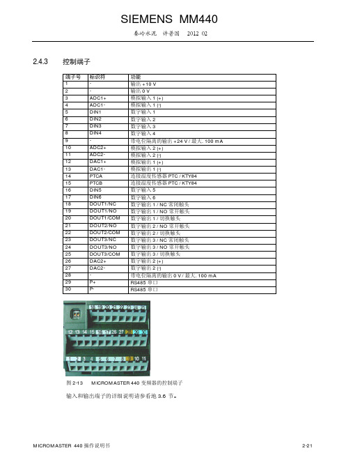
2.4.3 控制端子端子号标识符 功能1 - 输出 +10 V2 -输出 0 V3 ADC1+ 模拟输入 1 (+)4 ADC1- 模拟输入 1 (-)5 DIN1 数字输入 16 DIN2 数字输入 27 DIN3 数字输入 38 DIN4 数字输入 49 -带电位隔离的输出 +24 V / 最大. 100 mA 10 ADC2+ 模拟输入 2 (+) 11 ADC2- 模拟输入 2 (-) 12 DAC1+ 模拟输出 1 (+) 13 DAC1- 模拟输出 1 (-)14 PTCA 连接温度传感器 PTC / KTY84 15 PTCB 连接温度传感器 PTC / KTY84 16 DIN5 数字输入 5 17 DIN6数字输入 618 DOUT1/NC 数字输出 1 / NC 常闭触头 19 DOUT1/NO 数字输出 1 / NO 常开触头 20 DOUT1/COM 数字输出 1 / 切换触头 21 DOUT2/NO 数字输出 2 / NO 常开触头 22 DOUT2/COM 数字输出 2 / 切换触头 23 DOUT3/NC 数字输出 3 / NC 常闭触头 24 DOUT3/NO 数字输出 3 / NO 常开触头 25 DOUT3/COM 数字输出 3 / 切换触头 26 DAC2+ 数字输出 2 (+) 27 DAC2- 数字输出 2 (-)28 - 带电位隔离的输出 0 V / 最大. 100 mA 29 P+ RS485 串口 30P-RS485 串口图2-13 MICROMASTER 440 变频器的控制端子输入和输出端子的详细说明请参看地 3.6 节SIEMENS MM440秦岭水泥 许普国 2012.02功能(no filter function)allows direct access to the parameters.For BOP and AOP depending on the selected access levelconcerning the inverter unit Parameters level 1, 2, 3 and 4concerning the inverter unit Alarms, Warnings &Monitoring图3-3 参数的分类(组)/访问级无参数过滤功能可以直接访问参数 对于AOP 取决于选定的访向级 报警警告和监控12123功能3.1.2 互联连接的信号(BICO功能)具有现代先进技术水平的变频器必须能够实现内部和外部信号(设定值/实际值和控制信号/状态信号)的互联连接为了保证变频器能够与新的驱动对象相匹配这种互联连接功能必须具有高度的灵活性而且它还必须具有高度的可用性能够满足标准应用的要求因此MICROMASTER系列的变频器既引进了BICO功能(→灵活性)又具有参数P0700/P1000的快速参数化功能(→可用性)可以满足以上两种要求3.1.2.1 选择命令信号源(P0700)/选择设定值信号源(P1000)以下的参数可用于快速互联连接设定值和控制信号¾ P0700 选择命令信号源¾ P1000 选择设定值信号源这些参数用于定义变频器通过哪个接口接收设定值或上电/断电命令表3-2中列出的接口用于选择命令信号源( 参数P0700)表 3-2 参数 P0700参数的数值含义 / 命令源0 工厂缺省设置1 BOP (操作面板请参看 3.2.1 节)2 由端子板上的端子接入信号4 通过BOP 链路的 USS 设置5 通过COM 链路的USS 设置6 通过COM 链路的CB 设置频率设定值信号源P1000由下面的内部或外部信号源/接口来选择除了主设定值(第一位置)以外还可以选择一个辅助设定值(第二位置) (请参看表3-3)表3-3 参数 P1000含义参数的数值主设定值信号源辅助设定值信号源0 无主设定值-1 MOP 设定值 (电动电位计) -2 模拟设定值-3 固定频率设定值-4 通过BOP 链路的 USS 设置-5 通过COM 链路的USS 设置-6 通过COM 链路的CB 设置-7 模拟设定值 2 -10 无主设定值 MOP设定值11 MOP 设定值 MOP设定值12 模拟设定值 MOP设定值… .. ..… .. ..… .. ..77 模拟设定值2 模拟设定值2功能3.2.3 操作板 (BOP / AOP) 的按键及其功能显示/按钮功能功能的说明状态显示 LCD显示变频器当前所用的设定值起动电动机按此键起动变频器缺省值运行时此键是被封锁的为了使此键的操作有效应按照下面的数值修改P0700 或 P0719 的设定值BOP P0700 = 1 或 P0719 = 10 (16)AOP P0700 = 4 或 P0719 = 40 ….46 对 BOP 链路P0700 = 5 或 P0719 = 50 ….56 对 COM 链路停止电动机OFF1按此键变频器将按选定的斜坡下降速率减速停车缺省值运行时此键被封锁为了允许此键操作请参看起动电动机按钮的说明OFF2按此键两次(或一次但时间较长)电动机将在惯性作用下自由停车此功能总是使能的改变电动机的方向按此键可以改变电动机的转动方向电动机的反向用负号()表示或用闪烁的小数点表示缺省值运行时此键是被封锁的为了使此键的操作有效请参看起动电动机按钮的说明电动机点动在变频器准备运行的状态下按下此键将使电动机起动并按预设定的点动频率运行释放此键时变频器停车如果变频器 / 电动机正在运行按此键将不起作用功能此键用于浏览辅助信息变频器运行过程中在显示任何一个参数时按下此键并保持不动 2 秒钟将显示以下参数值1. 直流回路电压 (用d 表示– 单位V)2. 输出电流 (A)3. 输出频率 (Hz)4. 输出电压 (用 o 表示 – 单位V)5. 由P0005选定的数值(如果P0005选择显示上述参数中的任何一个 (1-4)这里将不再显示)连续多次按下此键将轮流显示以上参数跳转功能在显示任何一个参数rXXXX或PXXXX)时短时间按下此键将立即跳转到r0000如果需要的话您可以接着修改其它的参数跳转到 r0000后按此键将返回原来的显示点退出在出现故障或报警的情况下按键可以对它进行确认并将操作板上显示的故障或报警信号复位参数访问按此键即可访问参数增加数值按此键即可增加面板上显示的参数数值减少数值按此键即可减少面板上显示的参数数值+AOP 菜单直接调用 AOP 主菜单 (仅对 AOP 有效)图3-14 操作面板上的按键功能3.2.4 利用操作板更改参数下面的插图介绍更改参数P0004数值的步骤并以P0719为例说明如何修改下标参数的数值按照这个图表中说明的类似方法可以用BOP更改任何一个参数更改 P0004 – 参数过滤功能操作步骤显示的结果1 按访问参数2 按直到显示出 P00043 按进入参数访问级4 按或达到所需要的数值5 按确认并存储参数的数值6 使用者只能看到命令参数修改下标参数 P0719 – 选择命令/频率设定值源操作步骤显示的结果1 按访问参数2 按直到显示出 P07193 按进入参数数值访问级4 按显示当前的设定值5 按或选择运行所需要的数值6 按确认和存储这一数值7 按直到显示出 r00008 按返回操作显示 (由用户定义显示的参数)图3-15 利用 BOP 更改参数说明修改参数的数值时BOP有时会显示表明变频器正忙于处理优先级更高的任务功能3.3 方框图L/L1, N/L2L/L1, N/L2,L3ADC20 - 20 mA max. 500 ?~0 - 20 mA max. 500 ?Output 0 V max. 100 mA (isolated)30 V DC / 5 A (resistive)250 V AC / 2 A (inductive)DIP switch(on I/O Board)DIP switch (on Control Board)0V max.100mA 带隔离的500 500DIP 开关 在板上DIP 开关 在控制板上L/L1N/L2 L/L1N/L2L3 30VDC/5A 电阻负载250VAC/2A 感性负载功能3.4 工厂设置值MICROMASTER 变频器在出厂装船时带有状态显示板(SDP 参看图3-17) SDP 上有两个 LED 用于显示变频器的工作状态 (参看 第 4.1 节)在MICROMASTER 变频器按SDP功能出厂装船时不需 要任何参数化就可以投入运行在这种情况下变频器的缺省设置 (与变频器的型号和容量有关) 是 按4极电动机 的以下数据进行配置的¾ 电动机的额定功率 P0307 ¾ 电动机的额定电压 P0304 ¾ 电动机的额定电流 P0305 ¾ 电动机的额定频率 P0310(我们建议您采用西门子生产的标准电动机)而且必须满足以下条件¾ 由数字输入端控制 (ON/OFF 命令) (参看表3-5) ¾ 通过模拟输入1 输入设定值 P1000 = 2 ¾ 感应电动机P0300 = 1 ¾ 电动机冷却方式为自冷 P0335 = 0 ¾ 电动机的过载系数P0640 = 150 %¾ 最小频率P1080 = 0 Hz ¾ 最大频率P1082 = 50 Hz ¾ 斜坡上升时间P1120 = 10 s ¾ 斜坡下降时间P1121 = 10 s ¾ 线性的 V/f 特性 P1300= 0 表3-5数字输入的预先配置数字输入端子参数 功能激活 命令信号源 - P0700 = 2 端子板 是 数字输入 1 5 P0701 = 1 ON / OFF1 是 数字输入 2 6 P0702 = 12 反转 是 数字输入 3 7 P0703 = 9 故障确认是 数字输入 4 8 P0704 = 15 固定频率设定值(直接方式) 否 数字输入 5 16 P0705 = 15 固定频率设定值(直接方式) 否 数字输入 6 17 P0706 = 15 固定频率设定值(直接方式) 否 数字输入 7 经由 ADC1 P0707 = 0 禁止数字输入 否 数字输入 8经由 ADC2P0708 = 0禁止数字输入否图 3-17 状态显示板 (SDP)P0702=2,反转如果满足各个先决条件并且具备下面的条件那么在连接好电动机和电源以后出厂的设置参数就可以投运 ¾ 起动和停止电动机 (用外接开关经 DIN1 进行控制) ¾ 改变电动机的转动方向 (用外接开关经 DIN2 进行控制) ¾ 故障复位 (用外接开关经 DIN3 进行控制) ¾ 输入频率设定值 (用外接电位计经 ADC1 进行控制ADC 的缺省设置电压输入)¾ 可以输出频率实际值(经 D/A转换器D/A 转换器的输出为电流输出)Analog output 参看表3-5图3-18 按照工厂设置推荐的接线方法如果设置的参数不得不超过出厂设置的范围那么在进行传动系统的调试时根据工程应用的复杂程度必须对特定的功能说明以及参数表(包括功能框图) 进行仔细的研究模拟输出3.5.1 50/60 Hz 电源频率的设置出厂时变频器的电源电压频率是利用I/O 板下的DIP2(2) 开关 (参看图3-19) (如何拆卸 I/O 板请参R e m o v e I /O b o a r d DIP2(2)图3-19 设置电源频率 50/60 Hz 的DIP 开关DIP 开关(2)用于根据下面的框图确定参数 P0100 的数值(0 或1) 哪个有效 (参看图3-20)除了P0100 = 2 以外在电源电压接通以后 DIP2(2) 开关确定电源频率的设置值 是50 Hz 还是60 的参数数值0或1)P0100 = 2P0100 = 2?yes noyesnonoQuickcommissioning P0010 = 1Power cycle图 3-20 与P0100关联的DIP2(2)开关的操作方式上电 快速调试功能改变 DIP2(2) 开关的设置时在变频器断电接着再上电以后电动机额定频率 P0310最大频率 P1082 以及基准频率P2000 的参数单位都在这里自动预设定此外电动机的额定参数以及由电动机额定参数决定的所有其他参数都被复位功率的单位决定于参数 P0100用 kW 或 hp 表示 说明 I/O 板下控制板上的开关 DIP2(1) (参看图3-19)没有功能3.5.2 快速调试如果变频器还没有进行适当的参数设置那么在采用闭环矢量控制和 V/f 控制的情况下必须进行快速调试同时执行电动机技术数据的自动检测子程序以下的操作装置都可以用来进行快速调试 ¾ BOP ¾ AOP¾ PC 工具 (带有调试软件 STARTER DriveMonitor)进行快速调试以后可以使电动机 –变频器得到基本的调试在开始进行快速调试之前必须得到修改或键入以下的技术数据 ¾ 键入电源电压的频率 ¾ 键入电动机的额定铭牌数据 ¾ 命令 / 设定值信号源¾ 最小 / 最大频率或斜坡上升 / 斜坡下降时间 ¾ 闭环控制方式¾ 电动机技术数据的自动检测用 BOP 或 AOP 进行变频器的参数化带有*号标记的参数可以提供更多的设置(比下面表中实际列出的设置更多)关于其他设置的出厂时的缺省设置用黑体字标示用户访问级 *1标准级 (基本的应用) 2扩展级 (标准应用) 3专家级 (复杂的应用) 参数过滤器 * 0全部全部参数参数 2变频器 3电动机 4速度传感器调试参数过滤器 * 0准备 1快速调试30工厂的缺省设置值 (参看第3.5.7节) 说明参数P0010 应设定为 1以便进行电动机铭牌数据的参数化调试完P0010要回到0功能P0100 = 1 2欧洲/ 北美 (键入电源电压的频率) 0欧洲[kW]频率缺省值50 Hz 1北美 [hp]频率缺省值60 Hz 2北美 [kW]频率缺省值60 Hz说明 在参数P0100 = 0 或 1的情况下P0100 的数值哪个有效决定于开关 DIP2(2) 的设置 (参看参数表) OFF= kW 50 Hz ON= hp 60 Hz变频器的应用 (键入需要的转矩)0恒转矩(例如压缩机生产过程恒转矩机械) 1变转矩(例如水泵风机) 说明这一参数只对 ≥ 5.5 kW / 400 V 的变频器有效选择电动机的类型1异步电动机 (感应电动机) 2同步电动机 说明在 P0300 = 2 (同步电动机) 的情况下只允许V/f 控制方式 (P1300 < 20)电动机的额定电压(根据电动机的铭牌数据键入 (图3-21) 单位V)必须按照星形/三角形绕组接法核对电动机铭牌上的电动机额定电压 确保电压的数值与电动机端子板上实际配置的电路接线方式相对应电动机的额定电流(根据电动机的铭牌数据键入 (图3-21)单位A)电动机的额定功率(根据电动机的铭牌数据键入 (图3-21)单位kW / hp)如果 P0100 = 0 或 2那么应键入 kW 数如果 P0100 = 1应键入 hp 数电动机的额定功率因数(根据电动机的铭牌数据键入 (图3-21)cos ϕ) 如果设置为 0变频器将自动计算功率因数的数值 电动机的额定效率 (根据电动机的铭牌数据键入 (图3-21)以 %值输入) 如果设置为0变频器将自动计算电动机效率的数值 电动机的额定频率 (根据电动机的铭牌数据键入 (图3-21)单位Hz) 电动机的极对数是变频器自动计算的 电动机的额定速度 (根据电动机的铭牌数据键入 (图3-21)单位RPM) 如果设置为 0额定速度的数值是在变频器内部进行计算的 说明对于闭环矢量控制带FCC 功能的V/f 控制以及滑差补偿方式必须键入 这一参数电动机的冷却 (键入电动机的冷却系统) 0利用安装在电动机轴上的风机自冷 1强制冷却采用单独供电的冷却风机进行冷却 2 自冷和内置冷却风机 3强制冷却和内置冷却风机电动机的过载因子 (以 % 值输入参看P0305) 这一参数确定以电动机额定电流(P0305)的%值表示的最大输出电流限制值在恒转矩方式(由P0205确定)下这一参数设置为150 % 在变转矩方式 下 这一参数设置为 110 %功能选择命令信号源 * (键入命令信号源)0 将数字 I/O 复位为出厂的缺省设置值 1 BOP (变频机键盘) 2 由端子排输入 (出厂的缺省设置) 4 通过BOP 链路的 USS 设置5 通过 COM 链路的USS 设置(经由控制端子 29 和 30)6 通过 COM 链路的CB 设置(CB = 通讯模块) 选择频率设定值 *(键入频率设定值信号源)1 电动电位计设定 (MOP 设定)2 模拟输入 (工厂的缺省设置)3 固定频率设定值4 通过BOP 链路的 USS 设置5 通过COM 链路的 USS 设置 (控制端子 29 和 30)6 通过COM 链路的 CB 设置 (CB = 通讯模块)7 模拟输入 2最小频率(键入电动机的最低频率单位Hz)输入电动机的最低频率达到这一频率时电动机的运行速度将与频率的设定值无关这里设置的值对电动机的正转和反转都是适用的 最大频率(键入电动机的最高频率单位Hz)输入电动机的最高频率达到这一频率时 电动机的运行速度将与频率的设定值无关这里设置的值对电动机的正转和反转都是适用的 斜坡上升时间(键入斜坡上升时间单位s)电动机从静止停车加速到电动机最大频率P1082所需的时间如果参数化时 使斜坡上升时间太短那么可能出现报警信号 A0501 (电流达到限制值) 或变频器因故障 F0001 (过电流)而停车斜坡下降时间(键入降速时的斜坡下降时间单位s)电动机从最大频率P1082制动减速到静止停车所需的时间如果参数化时使斜坡下降时间太短那么可能出现报警信号A0501(电流达到限制值) A0502(达到过电压限制值)或变频器因故障 F0001 (过电流) 或F0002 (过电压)而断电OFF 3 斜坡下降时间 (键入快速停车的斜坡下降时间单位s)发出OFF3(快速停车)命令后电动机从最大频率P1082制动减速到静止停车所需的时间如果参数化时 使斜坡下降时间太短那么可能出现报警信号 A0501 (电流达到限制值) A0502(达到过电压限制值)或变频器因故障 F0001 (过电流) 或F0002 (过 电压)而断电 控制方式(键入实际需要的控制方式) 0 线性V/f 控制1 带FCC(磁通电流控制)功能的V/f 控制2 抛物线V/f 控制5 用于纺织工业的V/f 控制6 用于纺织工业的带FCC 功能的V/f 控制 19 带独立电压设定值的V/f 控制 20 无传感器矢量控制 21 带传感器的矢量控制 22 无传感器的矢量转矩控制 23 带传感器的矢量转矩控制功能选择转矩设定值 *(键入转矩设定值的信号源) 0 无主设定值 2 模拟设定值4 通过BOP 链路的 USS 设置5 通过COM 链路的 USS 设置 (控制端子 29 和 30)6 通过COM 链路的 CB 设置 (CB = 通讯模块)7 模拟设定值 2选择电动机技术数据自动检测 * (参看第3.5.4节) 0 禁止自动检测 1 自动检测全部参数并改写参数数值这些参数被控制器接收并用于控制器的控制 2 自动检测全部参数单不改写参数数值 显示这些参数但不供控制器使用 3 饱和曲线自动检测并改写参数数值生成报警信号A0541 (电动机机技术数据自动检测功能激活) 在得到后续的ON 命令时进行检测快速调试结束 (起动电动机数据的计算)0 不进行快速调试 (不进行电动机数据计算) 1 进行电动机数据计算不包括在快速调试中的其他全部参数(属性QC =no )都复位为出厂时的缺省设置值 2 进行电动机技术数据计算并将 I/O 设置复位为出厂时的缺省设置 3 只进行电动机技术数据计算其他参数不复位 说明在P3900 = 12 3 时 P0340 内部设定为 1 并计算相应的数据(参看参数表 P0340)显示表示正在计算控制数据 (闭环控制)然后与参数一起从 RAM 拷贝到 ROM 完成快速调试后重新显示P3900 说明此后不允许变频器断电因为 P1910 没有存储起动电动机技术数据的自动检测电动机技术数据自动检测程序由 ON 命令起动 (工厂设置DIN1)这时电流流过电动机并校准转子如果电动机技术数据自动检测程序运行完毕数据将由 RAM 拷贝到 ROM 同时显示 完成快速调试以后报警信号 A0541 (电动机技术数据自动检测程序激活) 自动撤消重新显示 P3900快速调试结束 / 变频器设置如果变频器运行时必须完成辅助功能请参看说明书变频器如何与工程应用相适配和工艺技术的相互联系我们建议您采用以上这些步骤使变频器具有良好 的动态响应特性Attion功能工厂的缺省设置电动机运行的环境温度是指进行电动机技术数据检测时20 °C)Motortemp. - P06255 癈Motor temp. − 5 癈电动机本身的温度与电动机运行环境温度如果大电动机技术数据自动检测程序只能在电动机的实际温度冷却下来以后才冷却电动机选择电动机技术数据自动检测功能0 禁止自动检测功能1 自动检测电动机的全部参数并修改参数数值2 这些修改后的参数被控制器接收并用于控制器的控制3 自动检测饱和(磁化)曲线并修改参数数值 说明在 P1910 = 1的情况下 P0340 在变频器内部设定为 3 并计算相应的 数据 (参看参数表中的参数 P0340)电动机上电接入ON 命令后 变频器开始进行电动机技术数据的检测与此同时电动机转子进行校准(移动到一个最佳位置)并导入电流通过 r0069 (CO 相电流) 来诊断检测中是 否有问题发生还输出报警信息 A0541 (电动机技术数据自动检测程序激活)电动机技术数据自动检测程序执行完毕以后 1. P1910 复位 (P1910 = 0) 2. 撤消A0541 的报警信号选择电动机技术数据自动检测功能0 禁止自动检测功能1 自动检测电动机的全部参数并修改参数数值2 这些修改后的参数被控制器接收并用于控制器的控制3 自动检测饱和(磁化)曲线并修改参数数值 说明在 P1910 = 1的情况下 P0340 在变频器内部设定为 3 并计算相应的 数据 (参看参数表中的参数 P0340)电动机上电电动机技术数据自动检测程序执行完毕以后1. P1910 复位 (P1910 = 0)2. 撤消A0541 的报警信号如果在检测电动机技术参数的过程中出现了问题例如电流控制器发生振荡那么应重新检查键入变频器的电动机铭牌数据是否正确相应地键入的磁化电流 P0320 也应正确无误然后调用 P0340 = 1 (参看第3.5.3节) 重新起动电动机技术数据自动 检测程序功能3.5.5 调试中必须的应用对象工艺数据在电动机 –变频器驱动系统进行快速调试或进行串行通讯调试完毕以后应根据生产工艺的要求匹配变频器的参数并设定参数的数值作为例子必须仔细研究以下各点 ¾ 对变频器功能的要求 (例如是否需要PID 控制器对过程参数进行闭环控制) ¾ 对参数数值的限制 ¾ 对动态性能的要求 ¾ 起动转矩¾ 对负载冲击的要求 ¾ 过载能力 ¾ 故障诊断如果快速调试和串行通讯调试中没有涵盖工程应用对象需要的功能那么就必须对以下各节的功能说明或参数表加以研究并得出对策按照应用对象的要求配置变频器标记的参数具有比下面表中列出的更多设置值其他设置值的情况请参看参数表工厂的缺省设置值用黑体字标识用户访问级 *1 标准级 (基本应用)2 扩展级 (标准应用)3 专家级 (供复杂应用时使用)电源电压 (键入以 V 为单位的电压值)这一参数应键入加到变频器上的实际电源电压值键入的电压值同时也确定了直流回路过电压 / 欠电压的动作电平和投入制动的阀值电压过载时变频器的应对措施这一参数确定变频器对内部过温采取的应对措施0 降低输出频率 1 跳闸 (F0004)2 降低脉冲频率和输出频率然后跳闸 (F0004)(键入电动机的冷却系统)motor parameter outside the quickcommissioning ?参看第3.5.3节电动机 / 控制数据的计算由电动机 / 控制数据的计算来的参数以外是否已经确定了其他电功能0 禁止选择功能1 单通道编码器双通道正交编码器 (双通道)编码器每转一圈发出的脉冲数 P0408 受到所(f max = 300 kHz)工艺应用对象确定工艺应用对象和控制方式 (P1300)0 恒转矩1 水泵和风机3 简单的定位控制sensor ?P0601 = 00 无传感器PTC 热敏电阻KTY84变频器跳闸或降低 Imax (参看 P0610) 的10 %I2t 过温的应对措施0 除报警外无应对措施报警和降低 I max(这将引起输出频率降低)2 报警和跳闸 (F0011)0 出厂时的缺省设置值BOP (键盘)设置2 由端子排输入4 通过 BOP 链路的 USS 设置通过 COM 链路的USS 设置通过 COM 链路的CB(通讯板)设置带有温度传感器吗功能1 的功能 5 1 ON / OFF1命令2 的功能 6 反转3 的功能 79 故障确认4 的功能 8固定频率设定值(直接选择)5 的功能 16固定频率设定值(直接选择)6 的功能 17 固定频率设定值(直接选择)0 禁止数字输入1 接通正转 / OFF1命令2 接通反转 / OFF1命令3 OFF2 – 按惯性自由停车4 OFF3 – 按快速下降斜坡曲线停车 9 故障确认10 正向点动 11 反向点动 12 反转 13 MOP (电动电位计) 升速 (增加频率) 14 MOP 降速 (减少频率) 15 固定频率设定值 (直接选择) 16 固定频率设定值(直接选择 + ON 命令)17 固定频率设定值(BCD 码+ ON 命令)25 使能直流注入制动29 由外部信号触发跳闸33 禁止附加频率设定值 99 使能 BICO 参数化7 的功能 3 禁止数字输入 8 的功能 10 禁止数字输入ON > 3.9 V, OFF < 1.7 V(滤波时间) 0 无防颤动时间防颤动时间为 2.5 ms 防颤动时间为 8.2 ms 防颤动时间为12.3 ms数字输入 (PNP) 和低电平有效 (NPN) 进行切换 NPN 方式 ==> 低电平有效 1 PNP 方式 ==> 高电平有效数字输出1 的功能 1 的信号源 18(常闭)19(常开)20(公共点)变频器故障数字输数字输出出2 的功能 2 的信号源 端子 21(常开)22(公共点) 52.7 变频器报警频率设置值 0.0 禁止数字输出 52.0 变频器准备 52.1 变频器运行准备就绪52.2 变频器正在运行52.3 变频器故障 52.4 OFF2 停车命令有效 52.5 OFF3 停车命令有效52.6 禁止合闸 52.7 变频器报警52.8 设定值/实际值偏差过大BI数字输出3 的功能确定数字输出3 的信号源端子 23(常闭)24(常开)25(公共点)0.0 禁止数字输出52.9 PZD (过程数据)控制52.A 已达到最大频率选择频率设定值0 无主设定值1 MOP 设定值2 模拟设定值3 固定频率4 通过 BOP 链路的 USS 设定5 通过 COM 链路的USS 设定6 通过 COM 链路的CB 设定7 模拟设定值 2ADC 的类型定义模拟输入的类型并使能模拟输入的监控功能0 单极性电压输入 ( 0 至 +10 V)1 带监控的单极性电压输入 (0 至 10 V)2 单极性电流输入 (0 至 20 mA)3 带监控的单极性电流输入 (0 至 20 mA)4 双极性电压输入 (-10 至 +10 V )说明下面的下标对 P0756 至 P0760 的参数都有效下标 0 模拟输入 1 (ADC1)端子 3 4下标 1 模拟输入 2 (ADC2)端子 1011标定ADC的 x1 值 [V/mA]标定ADC的y1 值本参数设定本参数设定以 P2000 (基准频率)的%值表示的y1值标定ADC的 x2 值 [V/mA]标定ADC的 y2 值本参数设定本参数设定以 P2000 (基准频率)的%值表示的y2值P0760P0758P0761 > 00 < P0758 < P0760 || 0 > P0758 > P0760MOP 的设定值存储这一参数确定在发出OFF命令或断开供电电源之前已经激活的电动电位计(MOP)设定值是否要存储0 MOP 设定值不存储1 MOP 设定值存入P1040禁止 MOP 反向0 允许反向1 禁止反向MOP 的设定值确定由电动电位计(MOP)控制时的设定值P0757=P0761=4mAP0003=3,P0004=8,OPEN THE "ADC" AND "DAC"以上次工作频率工作,除非修改,用在取料机。
Getting_Started

VTune(TM) 性能分析器 Linux 版入门指南“VTune™ 性能分析器”提供有关代码性能的信息。
VTune 分析器可以告诉您性能问题所在,使得您可以将精力集中到调整工作上,在最短的时间内获得最大幅度的性能提升。
本指南旨在向您介绍 VTune 分析器的基本功能。
读完本指南之后,您将能够使用 VTune 分析器来分析代码,了解应该将调整精力集中到什么地方,以便获得最大幅度的性能提升。
本文将引导您完成调整示例应用程序的重复性过程,并引导您完成性能调整的各个阶段:•确定性能问题的位置•修改代码以消除问题•比较新代码与初始代码的性能目录免责声明与法律信息 (2)1 构建应用程序 (3)2 分析应用程序 (3)3 分析算法 (10)4 分析代码中的事件 (15)5 下一步 (19)VTune(TM) 性能分析器 Linux 版2 文档编号:309564-003CN免责声明与法律信息本文所含信息专门针对英特尔® 产品提供。
本文并未授予任何知识产权的许可证,无论是明确、暗示、禁止翻供还是其它任何形式。
除这些产品的“英特尔销售条款和条件”之规定外,英特尔概不承担任何其它义务,对于英特尔产品的销售与/或使用(包括适合特定用途、适销性或不侵犯任何专利权、版权或其它知识产权),英特尔不作任何明确或暗示的担保,也不承担任何赔偿责任。
英特尔产品无意用于医疗、救生、维持生命、危机控制、安全系统或核设施等用途。
英特尔随时可能更改技术规格与产品说明,如确有更改,恕不另行通知。
标有“保留”或“未定义”字样的任何功能或指令,其存在性与特性均不确定,设计人员切勿对此有所依赖。
英特尔保留这些供将来定义之用,对于因将来对它们的更改而导致的任何冲突或不兼容现象,英特尔概不承担任何责任。
MPEG 是 ISO 推行的视频压缩/解压缩国际标准。
MPEG 编解码器的实现或是支持 MPEG 的平台可能需要从包括英特尔公司在内的多家实体获取许可证。
MM440变频器简易调试
P1000 = 2 选择频率设定值 * (键入频率设定值信号源)
1 电动电位计设定 (MOP 设定)
2 模拟输入 (工厂的缺省设置))
3 固定频率设定值
4 通过BOP 链路的 USS 设置
5 通过COM 链路的 USS 设置 (控制端子 29 和 30)
Text Box: P0100 = 1, 2
P0100 = 0
P0307 = ? 电动机的额定功率
(根据电动机的铭牌数据键入(图2.3),单位:kW / hp).
如果P0100 = 0或2,那么,应键入kW数,如果P0100 = 1,应键入hp
数。
P0308 = ? 电动机的额定功率因数
数化就可以投入运行。在这种情况下,变频器的缺省设置(与变频
器的型号和容量有关)是按4极电动机的以下数据进行配置的:
.. 电动机的额定功率 P0307
.. 电动机的额定电压 P0304
.. 电动机的额定电流 P0305
.. 电动机的额定频率 P0310
(建议您采用西门子生产的标准电动机。)
而且,必须满足以下条件:
.. 由数字输入端控制(ON/OFF命令) (参看表2-1)
.. 通过模拟输入1输入设定值 P1000 = 2
.. 感应电动机 P0300 = 1
.. 电动机冷却方式为自冷 P0335 = 0
.. 电动机的过载系数 P0640 = 150 %
.. 最小频率 P1080 = 0 Hz
3 电动机
4 速度传感器
P0010 = 1 调试参数过滤器 *
0 准备
如何通过UUS协议实现S7-1200与MM440通信

如何通过USS协议实现S7-1200 与MM440变频器的通信How to communication between S7-1200 and MM440 inverter by USS protocol摘要 本文介绍了通过USS 协议实现S7-1200 与MM440的通信。
关键词USS 协议,S7-1200,MM440,变频器Key Words USS protocol,S7-1200,MM440,Frequency converterIA&DT Service & Support Page 2-23目录如何通过USS协议实现S7-1200 与MM440变频器的通信 (1)1. USS通信介绍 (4)1.1. USS协议特点 (4)1.2. S7-1200 USS通信简介 (5)2. 硬件需求及接线 (6)2.1. 硬件需求 (6)2.2. 接线 (6)3. 组态 (9)3.1. PLC 硬件组态 (9)3.2. MM440参数设置 (10)4. USS通信原理与编程的实现 (12)4.1 S7 1200 PLC与MM440 通过USS通信的基本原理 (12)4.2. 功能块使用介绍 (14)4.3. S7 1200 PLC进行USS通信的编程 (14)4.3.1. USS_DRV功能块的编程 (14)4.3.2. USS通信接口参数功能块的编程 (16)4.3.3. USS_RPM功能块的编程 (18)4.3.4. USS_WPM功能块的编程 (18)4.3.5. 常见错误 (20)附录-推荐网址 (22)IA&DT Service & Support Page 3-23西门子S7-1200 PLC在当前的市场中有着广泛的应用,作为常与变频器共同使用的PLC,其与西门子MM440 变频器的USS通信一直在市场上有着非常广泛的应用。
本文将主要介绍如何使用USS通信协议来实现S7-1200与MM440变频器的通信。
DS2208数字扫描器产品参考指南说明书
-05 Rev. A
6/2018
Rev. B Software Updates Added: - New Feedback email address. - Grid Matrix parameters - Febraban parameter - USB HID POS (formerly known as Microsoft UWP USB) - Product ID (PID) Type - Product ID (PID) Value - ECLevel
-06 Rev. A
10/2018 - Added Grid Matrix sample bar code. - Moved 123Scan chapter.
-07 Rev. A
11/2019
Added: - SITA and ARINC parameters. - IBM-485 Specification Version.
No part of this publication may be reproduced or used in any form, or by any electrical or mechanical means, without permission in writing from Zebra. This includes electronic or mechanical means, such as photocopying, recording, or information storage and retrieval systems. The material in this manual is subject to change without notice.
ABB PSR软启动器产品说明书

DescriptionThe PSR range is the most compact of all ABB’s softstarter ranges. The compact PSR range makes it possible to fit many devices into the same enclosure. A PSR together with a MMS (manual motor starter) makes up a far more compact starting solution than a Star-Delta starter, for instance.Flexible mountingPSR softstarters from 3 to 45 A are possible to mount on a DIN-rail, ensuring quick and easy mounting. Naturally, all sizes can be screw mounted.Few settingsThe setup of the PSR is easily done and confirmed using the three clearly marked potentiometers on the front.Built-in by-pass for energy savingThe built-in by-pass on all sizes does not only save energy; it will also ensure the most compact ABB’s softstarter design and reduce the installation time. Thanks to the reduced heat generation, the softstarter can be mounted inside high IP class enclosures.Suitable for stopping pumpsEven without using torque control, the PSR range is designed to reduce water hammering. Compared to the direct stops of a Star-Delta starter or a DOL starter the PSR is superior. See the stop ramp with step-down voltage below.System concept with manual motor startersAll PSR softstarter sizes can easily be connected to the corresponding manual motor starters from ABB by using the special designed connection kits. This makes both the mounting and the connection easier and will provide a very compact starting solution containing short circuit and thermal protection, isolation function and soft starter - everything that you need.Start = 1 ... 20 secStop = 0 ... 20 sec - including the step down voltage.Step down = 2% reduction for each second increased stop ramp Stop ramp 10 sec -> step down 80% (20% reduction) U ini = 40 ... 70% results in end voltage = 30 ... 60%321Uend3OverviewPSR3 ... PSR16PSR25 ... PSR30PSR37... PSR45PSR60 ... PSR105Softstarter, typeNormal startIn-line connectedPSR3PSR6PSR9PSR12PSR16PSR25PSR30PSR37PSR45PSR60PSR72PSR85PSR105(400 V) kW 1.53 4 5.57.5111518.52230374555IEC, max. A 3.9 6.89121625303745607285105(440-480 V) hp 2357.5101520253040506075UL, max FLA 3.46.191115.224.2283446.259.46880104400 V , 40 ºCProduct description• Wide rated operational voltage 208–600 V• Rated control supply voltage 24 V AC/DC or 100–240 V AC • Rated operational current 3–105 A• Wide ambient temperature range, -25 to +60 ºC • Built-in by-pass on all sizes, saving energy and reducing installation time • Potentiometer settings • Run signal relay on all devices• TOR signal relay on PSR25 … PSR105• Optional fieldbus communication using Profibus, Modbus,Devicenet or CANopen• DIN rail mounting on PSR3 … PSR45• Screw mounting on all sizes• Connection kits for easy connection with ABB’s manual motor starters• Sophisticated algorithm eliminating the DC-component and thereby providing excellent starting performanceSettingsOrdering details PSR3 ... PSR105AccessoriesPSLW1S F C 132012F 02021S F C 132171F 00011S F C 132169F 0001PSR45-MS4501S F C 132170F 0001PSR105-MS4951S F C 132208F 0002PSR30-MS1321S F C 13224F 0001Connection kitPSR-FAN60-105AThermal motor overload protectionShort circuitprotectionSoftstarter providing excellent start and stopIsolating functionConnection device PSR-FAN3-45APSR3 ... PSR161S F C 132297F 0002PSR25 ... PSR301S F C 132298F 0002PSR37 ... PSR451S F C 132299F 0002PSR60 ... PSR1051S F C 132300F 0002PS-FBPAPSR16-MS1161S F C 132325F 00011S F C 132168F001Technical data UL ratingsSoftstarterMotor power P (hp) and full load current FLA (A)Max U eU eU eU eMax. fuse Type FLA A 200 V/208 V hp 220 V/240 V hp 440 V/480 V hp 550 V/600 V hp A, Type PSR33.40.50.752235 A J-Type PSR6 6.11 1.53535 A J-Type PSR992257.535 A J-Type PSR1211337.51035 A J-Type PSR1615.235101035 A J-Type PSR2524.27.57.5152060 A J-Type PSR30287.510202560 A J-Type PSR37341010253090 A J-Type PSR4546.21515304090 A J-Type PSR6059.420204050110 A J-Type PSR726820255060125 A J-Type PSR858025306075150 A J-Type PSR105104304075100200 A J-TypeRated insulation voltage U i 600 VRated operational voltage U e208...600 V +10%/-15%, 50/60 Hz ±5%Rated control supply voltage U s 100...240 V AC, 50/60Hz ±5% or 24 V AC/DC, +10%/-15%, Power consumption PSR3PSR6PSR9PSR12PSR16PSR25PSR30PSR37PSR45PSR60PSR72PSR85PSR105Supply circuitat 100-240 V AC 12 VA10 VAat 24 V AC/DC5 W Max. Power loss at rated I e PSR3PSR6PSR9PSR12PSR16PSR25PSR30PSR37PSR45PSR60PSR72PSR85PSR1050.7 W 2.9 W 6.5 W 11.5 W20.5 W25 W36 W5.5 W8.1 W3.6 W5.2 W7.2 W6.6 WStarting capacity at I e4 x Ie for 6 sec.Number of starts per hourSee table below for details standard 101)with aux. fan201)Service factor100%Ambient temperatureduring operation -25 ºC to +60 ºC 2)during storage-40 ºC to +70 ºC Maximum altitude 4000 m 3)Degree of protectionPSR3PSR6PSR9PSR12PSR16PSR25PSR30PSR37PSR45PSR60PSR72PSR85PSR105main circuit IP20IP10control circuitIP20Connectable cable areaPSR3-PSR16PSR25-PSR30PSR37-PSR45PSR60-PSR105main circuit1 x 0.75-2.5mm2 1 x 2.5-10mm 2 1 x 6-35mm 2 1 x 10-95mm 22 x 0.75-2.5mm 2 2 x 2.5-10mm 22 x 6-16mm 22 x 6-35mm 2PSR3-PSR16PSR25-PSR105control circuit1 x 0.75-2.5mm2 1 x 0.75-2.5mm 22 x 0.75-2.5mm 2 2 x 0.75-1.5mm 2Signal relaysPSR3-PSR16PSR25-PSR105for run signalresistive load240 V AC, 3 A/24 V DC, 3 A 240 V AC, 3 A/24 V DC, 3 A AC-15 (contactor)240 V AC, 0.5 A/24 V DC, 0.5 A240 V AC, 0.5 A/24 V DC, 0.5 A for top ramp signalresistive load-240 V AC, 3 A/24 V DC, 3 A AC-15 (contactor)-240 V AC, 0.5 A/24 V DC, 0.5 ALED for On/Readygreen for Run/Top of ramp green Settings Ramp time during start 1-20 sec. Ramp time during stop 0-20 sec. Initial- and end voltage40-70%1) Valid for 50% on time and 50% off time. If other data is required, contact your sales office.2)Above 40 ºC up to max. 60 ºC reduce the rated current with 0.8% per ºC.3)When used at high alitudes above 1000 meters up to 4000 meters you need to derate the rated current using the following formula.[ % of I e = 100 - x-1000 ] x = actual altitude for the softstarter 150UL ratingsNumber of starts per hour using PSR softstartersMotor current Starts/hour without auxiliary fan Starts/hour with auxiliary fanI e10203040506080100102030405060801003 A PSR3PSR6PSR36 A PSR6PSR9PSR6PSR99 A PSR9PSR12PSR16PSR25PSR9PSR1212 A PSR12PSR16PSR25PSR30PSR12PSR16PSR2516 A PSR16PSR25PSR30PSR37PSR16PSR25PSR3025 A PSR25PSR30PSR37PSR45PSR60PSR25PSR30PSR37PSR4530 A PSR30PSR37PSR45PSR60PSR72PSR30PSR37PSR4537 A 45 A 60 A 72 A 85 A 105 AeFor more optimized selections, or to use PSR for heavy-duty starts, please use the softstarter selection tool.。
- 1、下载文档前请自行甄别文档内容的完整性,平台不提供额外的编辑、内容补充、找答案等附加服务。
- 2、"仅部分预览"的文档,不可在线预览部分如存在完整性等问题,可反馈申请退款(可完整预览的文档不适用该条件!)。
- 3、如文档侵犯您的权益,请联系客服反馈,我们会尽快为您处理(人工客服工作时间:9:00-18:30)。
西门子自动化驱动集团
客户支持部
Communication ConnectionsFieldbus Systems
Different Types
Profibus
Troubleshooting
STARTER 的简介
STARTER 的安装
STARTER 与传动装置建立连接
STARTER 快速调试
STARTER 基本功能
MM440调试软件
STARTER
STARTER的适用对象西门子自动化驱动集团
客户支持部
西门子自动化驱动集团
客户支持部
STARTER 安装后的设置
2. 2. 点击点击点击Starter Starter Starter,,进入欢迎界面进入欢迎界面,,在该界面上显示了在该界面上显示了Starter Starter Starter的版本号的版本号
STARTER与传动装置的连接西门子自动化驱动集团
客户支持部
西门子自动化驱动集团客户支持部STARTER 与传动装置的连接
与传动装置的连接--RS232 /RS485
1.RS232/RS485
1.RS232/RS485连接方式
连接方式
西门子自动化驱动集团
客户支持部
Communication ConnectionsFieldbus Systems
STARTER 与传动装置的连接与传动装置的连接--PROFIBUS 连接
驱动装置MM4可以配置PROFIBUS通讯模板,需要另外订货。
订货号为6SE6400-1PB00-0AA0
PC台式机侧需安装:
CP 5611卡支持PROFIBUS 通讯,订货号为:6GK1561-1AA00
笔记本则需要安装:
CP5512卡以及SIMATIC NET 适配器,订货号为:6GK1551-2AA00
系列
PROFIBUS 通讯模板
SIMATIC NET 适配器上PROFIBUS 接口
插入笔记本内的CP5512 2.PROFIBUS DP 2.PROFIBUS DP连接方式连接方式
西门子自动化驱动集团
客户支持部
Systems
STARTER 与传动装置的连接与传动装置的连接--PROFIBUS 连接
驱动装置侧的PROFIBUS通讯地址设置有两种方法:在拨码开关全部拨到OFF状态时可以利用参数P918设置地址
如果拨码开关没有全部拨到OFF状态,真实地址将以拨码开关的设置为准。
MM4的PROFIBUS 通讯波特率为自适应,不需要设置
拨码开关号
拨码开关代表的地址例如例如::1 地址= 3=1+2例如例如::2 地址= 88=8+16+64
新建工程组态
西门子自动化驱动集团
客户支持部打开STARTER软件》》》新建》》》New with wizard,出现下面对话框:
西门子自动化驱动集团客户支持部离线组态工程如下:
新建工程组态
新建工程组态
西门子自动化驱动集团
客户支持部点击“Change and test…”,出现下面对话框,根据实际通讯配置
通讯方式
确认退出,进入下面对话框;
西门子自动化驱动集团
客户支持部
Communication ConnectionsFieldbus Systems 新建工程组态
插入驱动装置
西门子自动化驱动集团
客户支持部
Systems
新建工程组态
Starter Starter工程界面工程界面
工具条
西门子自动化驱动集团客户支持部
新建工程组态在线
在线online/
online/
online/离线
离线
离线offline
offline
offline:
:
装置快速调试西门子自动化驱动集团
客户支持部
西门子自动化驱动集团
客户支持部
Communication ConnectionsFieldbus Systems 装置快速调试
快速基本参数设置
装置快速调试
应用标准
西门子自动化驱动集团
客户支持部
点击
西门子自动化驱动集团
客户支持部
Communication ConnectionsFieldbus Systems 装置快速调试
电机参数
同步/异步电机
电机冷却方式
西门子自动化驱动集团
客户支持部
Communication ConnectionsFieldbus Systems 装置快速调试
编码器参数
西门子自动化驱动集团
客户支持部
Communication ConnectionsFieldbus Systems 装置快速调试
编码器参数
西门子自动化驱动集团
客户支持部
Communication ConnectionsFieldbus Systems 装置快速调试
运行模式
西门子自动化驱动集团
客户支持部
Communication ConnectionsFieldbus Systems 装置快速调试
命令源
命令源//速度信号源
西门子自动化驱动集团
客户支持部
Communication ConnectionsFieldbus Systems 装置快速调试
主运行参数
西门子自动化驱动集团
客户支持部
Systems 装置快速调试
电机参数计算
西门子自动化驱动集团
客户支持部
Communication ConnectionsFieldbus Systems 装置快速调试
电机参数识别与优化
选择“Motor
identification”
西门子自动化驱动集团客户支持部
STARTER
STARTER基本功能
基本功能1.Control Panel
1.Control Panel功能
功能
装置快速调试西门子自动化驱动集团
客户支持部
Systems
装置快速调试西门子自动化驱动集团
客户支持部
Communication ConnectionsFieldbus Systems
西门子自动化驱动集团
客户支持部
Communication ConnectionsFieldbus Systems 装置快速调试
2.
2.上传备份变频器参数
上传备份变频器参数
点击
装置快速调试西门子自动化驱动集团
客户支持部
Communication ConnectionsFieldbus Systems
西门子自动化驱动集团
客户支持部
Communication ConnectionsFieldbus Systems
Different Types
Profibus
Troubleshooting
STARTER 的简介
STARTER 的安装
STARTER 与传动
装置建立连接
STARTER 快速调试
STARTER 基本功能
装置快速调试
3.3.把备份的参数下载到变频器把备份的参数下载到变频器
点击
点击“Yes”
装置快速调试西门子自动化驱动集团
客户支持部
Communication ConnectionsFieldbus Systems
西门子自动化驱动集团
客户支持部
Communication ConnectionsFieldbus Systems 装置快速调试
4.
4.专家参数列表
专家参数列表
专家参数模式下,可以修改在此状态下允许更改的参数,以及监控变频器运行状态!
西门子自动化驱动集团
客户支持部
Systems 装置快速调试
5.
5.工厂复位变频器参数
工厂复位变频器参数
在某些情况下需要对变频器参数进行工厂复位!
装置快速调试西门子自动化驱动集团
客户支持部
Communication ConnectionsFieldbus Systems
西门子自动化驱动集团
客户支持部
Communication ConnectionsFieldbus Systems
Different Types
Profibus
Troubleshooting
STARTER 的简介STARTER 的安装
STARTER 与传动装置建立连接
STARTER 快速调试
STARTER 基本功能
A&D CS
Siemens AG
E-Mail: ad.china@。