MasterCAM9.1的刀具清单功能
MasterCAM菜单功能列表

MasterCAM V9.0命令解说一览表主菜单说明Analyze分析分析并显示屏幕上图素的有关信息Create绘图绘制图素,建立2D,3D几何模型并完成工程作图File档案与文件有关的操作,包括文件的查询存取,编辑,浏览,打印,图形文件的转换,NC程序的传输等Modify修整修改几何图形,包括倒圆,修整,打断,连接,延伸,改变曲面法向,动态移位等Xform转换对图素或图素群组做图形变换,包括镜向,旋转,平移,单体补正,串连补正等Delete删除删除图形或恢复图形Screen屏幕改变屏幕上图素的显示属性Solids实体生成实体模型。
包括用挤出,旋转,扫掠,举升,倒圆角,倒角,薄壳,牵引,修整及布尔运算方法生成实体,以及实体管理Toolpaths 刀具路径生成2D,3D的刀具路径和NC程序,包括处理二维外形铣削,钻孔等点位加工,带岛的挖槽加工,单曲面加工,多重曲面加工,投影曲面铣削,线框模型处理3D加工以及操作管理,工作设定等NC Utils 公用管理包括实体验证,路径模拟,批处理加工,程式过滤,后处理,加工报表,定义操作,定义刀具,定义材料等辅助菜单说明Z Z值设置工作深度Z值Color作图颜色设定绘制图形的颜色Level作图层别设定绘制图形的图层Attribute 图素属性设置绘制图形的颜色、层别、线型、线宽、点的型式等属性及对各种类型图素的属性管理Groups群组设定将多个图素定义为一群组Mask限定层限定层,即设定系统认得出的图层。
例如限定某一层,则绘制在该层的图素才能被选择,完成诸如分析,删除等操作。
设置OFF,则系统可以认得出任何一个图层的图素WCS世界坐标系设置系统视角管理。
常用在图形文件转换肘,当有些构图面和视角与Mastercam软件不兼容时,可将其图素转正。
Plane刀具平面设定表示数控机床坐标系的二维平面C Plane构图平面建立工作坐标系。
包括建立空间绘图、俯视图、前视图、侧视图、视角号码、名称视角、图素定面、旋转定面、法线面等Gview视角设定图形观察视角构图平面说明3d3d空间绘图TOP俯视面Front前视面Side侧视面文档由风行播放器/暴风影音2014:/整理Number视角号码,1~8为系统默认,9号以上为用户新设定Named依系统视角管理中的WCS定面Entity图素定面,可以选一圆弧或二条线段或三个点或实体平面来定面Rotate旋转定面,当前平面绕着坐标轴旋转产生新的构图面Last前一次选择的面Normal法线面,选择一条线段作为构图面的法向矢量=Gview同视角Gview设定的面相同=Tplame同刀具平面Tplame设定的面相同+xz适于车床,以半径计X轴-xz适于车床,以半径计X轴,X轴反置+dZ适于车床,以直径计X轴-dZ适于车床,以直径计X轴,X轴反置图形视角说明TOP俯视图Front前视图Side侧视图Isometric等角视图Number根据视角号码来确定视角Named依系统视角管理确定视角Entity图素定面Rotate旋转定视角Dynamic动态视角,可以动态旋转、缩放、平移和任意改变视角Last前一次选择的视角Mouse鼠标定视角,可以旋转、缩放、平移和任意改变视角Normal法线定视角=Cplane以构图面设定的面作为视角=Tplane以刀具平面设定的面作为视角Create 绘图命令(一)Origin:原点(0,0)Center 一圆弧的圆心点Endpoint 一图素的端点Intersec 二图素的交点Midpoint 一图素的中点Point 已存在点Last 前一次操作点Relative 对某一已知点的相对点Rectang 直角坐标方式Polar极坐标方式Quadrant 圆四分之一处点Sketch 任意点P o i n t点Position 指定位置生成指定位置上的点Along ent 等分绘点沿着一个图素,生成一系列等距离的点Node pts 曲线节点生成参数样条曲线(parametric Spline)的节点Cpts NBS 控制点生成非均匀B 样条曲线(NURBS)的控制点Dynamic 动态绘点沿着一个图素,使用选点设备,动态生成一系列点Length 指定长度沿着一个图素,与端点一定距离,生成一个点Slice 剖切点生成一平面与不共面的线,弧,样条曲线间的交点Srf project 投影至面生成投影到曲面上的投影点(沿着曲面法向或垂直于构图平面投影)或生成通过投影点沿着曲面法向及给定长度的一矢量线Prep/Dist 法向/距离生成与一直线、圆弧或曲线法线上的相距给定距离的点Grid 网格点生成一系列网状点Boltcir 圆周点生成分布在一圆弧上的等分点Small arcs 小弧圆心生成小于给定半径的圆弧的圆心点L i n e 线段Horizontl 水平线生成与X 轴平行的线Vertical 垂直线生成与Y 轴平行的线Endpoint 两点画线生成通过二点的线Multi 连续线生成通过一组点的折线Polar 极坐标线给一任意点,角度及长度Tangent 切线Angle 给一个角度和长度,与一曲线相切的线2Arcs 与二圆弧相切的线point通过一点,与一曲线平行的线PeRpendcr 法线Point 通过一点,与一曲线垂直的线Arc 与一直线垂直,与一圆弧相切的线ParalleL平行线:与一直线平行,并且Slide/dist 给出方向和距离Point 给出一点,平行线通过给点Arc并且与一圆弧相切Bisect 分角线生成二线的角平分线Closest 连近距线在二曲线之间,生成一条最短距离的线A r c圆弧Polar 极坐标Ctr point 给出圆心点,半径值,起始角度值,终止角度值,绘制圆弧SKetch 给出圆心点,半径值,用鼠标选取起始角度和终止的位置生成圆或圆弧Strt point 给出起始点及半径值,起始角值,终止角值,生成圆或圆弧End point给出终止点及半径值,起始角值,终止角值,生成圆或圆弧Endpoint 两点画弧给出二端点及半径值,生成四个圆弧,选中其中一个3Points 叁点画弧通过给出的三点,生成圆弧Tangent 切弧1entity 与一图素相切,给出一点(近切点)和半径,生成四个半圆,选中其中一个2entities与二图素相切,给出半径,生成一整圆3entities 与三个图素相切,生成一切弧Ctr line 与二条相交直线中的一条直线相切,另一条直线通过圆心,给出半径,生成二整圆,选中其中一个point 通过一点,与一图素相切,给出半径,生成四个圆弧,选中其中一个Dynamic与一图素相切,动态给出其相切点,并动态生成一圆弧2pt cir 两点画圆给定二点为一直径,生成一个圆3pt cIr 叁点画圆通过给定三点,生成一个圆pt Rad cir给出圆心,半径,生成一个圆点半径圆pt Dia cir 点直径圆给出圆心,直径,生成一个圆pt edG cir 点边界圆给出圆心和圆上一点,生成一个圆F i l l e t 倒圆角对二个图素作倒圆角处理选择参数Radius 半径值Angle<180S 生成的圆弧小于180L 生成的圆弧小于180F生成一整圆Trim Y/N是否修整掉多余的Chain 对一封闭图形的每一个转角处倒圆角CW/CCW 连续倒圆的串连方式P 只倒出逆时针方向的圆N 只倒出顺时针方向的圆角A 所有方向都倒圆角S p l i n e 样条曲线选择参数Type P/N 曲线型式参数式样条曲线/非均匀有理B 样条曲线。
(一)Mastercam9.1学习
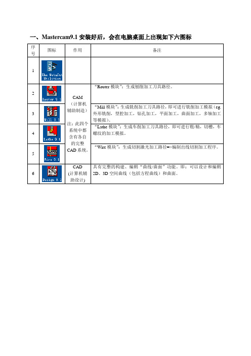
一、Mastercam9.1安装好后,会在电脑桌面上出现如下六图标序号图标作用备注12CAM(计算机辅助制造)注:此四个系统中都含有各自的完整CAD系统。
“Router模块”:生成刨削加工刀具路径。
3 “Mill模块”:生成铣削加工刀具路径,即可进行铣削加工模拟(eg.外形铣削,型腔加工,钻孔加工,平面加工,曲面加工,多轴加工等模拟)。
4 “Lathe模块”:生成车削加工刀具路径,即可进行粗/精,切槽,车螺纹的加工模拟。
5“Wire模块”:生成切割激光加工路径=>编制出线切割加工程序。
6CAD(计算机辅助设计)具有完整的构建、编辑“曲线/曲面”功能。
即:可以设计和编辑2D、3D空间曲线(包括方程曲线)和曲面。
二、点=>如下界面注:(一)标题栏:显示系统版本号+ 文件路径和名称。
(二)工具栏:集成“主菜单区”常用命令。
注:可用“/ ”来改变工具栏显示。
①Mastercam9.1所有功能都可通过主菜单中各项命令来实现;(三)主菜单区②单击主菜单中任一项,随后都会打开相应子菜单;③:返回上一级菜单;④:直接由多级子菜单直接返回主菜单。
①主菜单下的全为次菜单区;(四)次菜单区②主菜单区必须回到主功能表才能使用次菜单区;③提供了常用设置对象属性命令,包括层,颜色,样式/宽度,构图面选项等参数的设置。
三、M a s t e r c a m 9.1菜单 分类 序号图 标 作 用 主 菜 单 1显示绘图区所选图素的所有相关信息。
23对文档存储、取出、编辑、打印等操作。
4在绘图区修改图形(eg.倒角、修剪、打断、连接等)。
5转换图形用(eg.镜像、旋转、比例、平移、偏置等)。
67改变屏幕上显示的图形。
8绘制实体模型。
910编辑、管理、检查刀具路径。
1112次菜单13所绘图形的3D 深度。
14绘图时颜色设置。
15图层设置。
16对模型进行颜色、线型、图层、点的形式的设置。
17将某些属性相同的几何对象设置在一个群组中。
第一章 Mastercam 9.1基础知识
串连:定义一个或多个图素的边界 窗选 :使用光标画出的矩形窗口或 多边形窗口选取待串连的图素 面积 :用光标单个点取图素进行串 连形成多边界 单体 :只串连一条线,一个圆弧, 一条聚合线 分段串连 :串连一部分图素 单点 :只选择一个点 上一个:重新调用上一次的串连组 群操作 不选择:清除上次选取的串连
第一章 Mastercam 9.1基础知识 基础知识
1.2 Mastercam 9.1的启动与退出 的启动与退出 1、启动: A、开始→程序→Mastercam 9.1→Mill9.1 按钮 B B、双击桌面上的“Mill”图标 Mill” 2、退出: A、单击系统窗口右上角的关闭按钮 B、同时按下【Alt+F4】快捷键 C、依次选择菜单File→Next menu→Exit(文 件→下级菜单→返回)命令
第一章 Mastercam 9.1基础知识 基础知识
3、通用选择输入方法 依次选取MAIN MENU Xform Translate MAIN MENU→Xform→Translate(回主功能表 →转换→平移)命令,在主菜单区会打开Translate: Translate: select entities to translate (平移:选择要平移的图 素)菜单。
Page Up : 绘图视窗放大; Page Down: 绘图视窗缩小; ↑上箭头:绘图视窗上移(注:绘图区图形下移); ←左箭头:绘图视窗左移(注:绘图区图形右移); →右键头:绘图视窗右移(注:绘图区图形左移);; ↓下箭头:绘图视窗下移(注:绘图区图形上移); End:模型旋转; Esc:结束正在进行的操作,并返回上一级菜单; F1:视窗适度化; F2:视图缩小至原视图的0.5倍; F3:重画视图; F5:显示删除菜单; F9:显示当前坐标系; Alt + S:曲面渲染显示/关闭; :
MasterCAM9.1的刀具清单功能
breakarcs:0#Break arcs, 0 = no, 1 = quadrants, 2 = 180deg・max arcs
stagetool:0#0二Do not pre-stage tools, 1 = Stage tools
#
#Options/Usage:
#It is recommended to start and end cutter compensation oncjlinear move.
#Rotary axis assumes a”Z” plunge at feed into part, position of the
# 1二Output post to screen, 2二output leader to screen
#Append postline labels, norvzero is column position?
#Append whatline no. to each NC line?
#Append NCI line no. to each NC line?
#1thru 3 = Reference return is generated and G92 with the
#X, Y and Z home positions at each tool.
#4 thru 9 = The WCS of G54 thru G59 respectively at each tool.
# Axis output formats-Linear
fmt
X 1 x
# X axis position
Mastercam9

Mastercam9.1后处理指南简介本文档旨在为使用Mastercam9.1后处理功能的用户提供详细指南。
后处理是将Mastercam生成的刀具路径转化为机器能够理解并执行的代码的过程。
通过正确配置后处理器,您可以确保生成的代码与您的机床兼容,并实现高效准确的加工。
配置后处理器在使用Mastercam9.1后处理功能之前,您需要正确配置后处理器。
首先,打开Mastercam9.1软件,并导入您的设计文件。
然后,进入“后处理”选项,选择适合您机床的后处理器。
如果您找不到适合的后处理器,可以联系Mastercam官方支持获取帮助。
一旦选择了后处理器,您可以根据您的需要进行进一步的配置,例如设置刀具补偿、刀具半径补偿、切割速度等。
后处理输出在Mastercam9.1中,您可以生成多种类型的输出文件,包括NC程序文件、机器程序文件和刀具路径图。
生成这些文件是为了将您的加工数据传递给机床执行。
在生成这些文件之前,请确保您已正确配置后处理器并选择了正确的输出格式。
使用示例以下是一个简单的使用示例,展示了如何通过Mastercam9.1生成NC程序文件:1.在Mastercam9.1中,打开您的设计文件。
2.进入“后处理”选项,选择适合您机床的后处理器。
3.配置后处理器,例如设置好刀具补偿、刀具半径补偿、切割速度等。
4.点击“生成NC程序”按钮,选择输出文件的保存路径和文件名。
5.确认设置并点击“生成”按钮。
6.检查生成的NC程序文件,并将其传输给机床进行加工。
常见问题解答以下是一些常见问题的解答,以帮助您更好地使用Mastercam9.1后处理功能:1.Q: 如何选择合适的后处理器?A: 您可以从Mastercam提供的后处理器列表中选择适合您机床的后处理器。
如果找不到适合的后处理器,可以联系Mastercam官方支持。
2.Q: 如何配置后处理器的刀具补偿?A: 在配置后处理器时,您可以设置合适的刀具补偿数值,以确保加工效果符合预期。
MasterCAM 9.1 命令解说一览表
对图素或图素群组做图形变换,包括镜向,旋转,平移,单体补正,串
连补正等
Delete删除
删除图形或恢复图形
Screen屏幕
改变屏幕上图素的显示属性
Solids实体
生成实体模型。包括用挤出,旋转,扫掠,举升,倒圆角,倒角,薄壳,牵引,修整及布尔运算方法生成实体,以及实体管理
Toolpaths
Cpts NBS
控制点
生成非均匀B样条曲线(NURBS)的控制点
Dynamic
动态绘点
沿着一个图素,使用选点设备,动态生成一系列点
Length
指定长度
沿着一个图素,与端点一定距离,生成一个点
Slice
剖切点
生成一平面与不共面的线,弧,样条曲线间的交点
Srf project
投影至面
生成投影到曲面上的投影点(沿着曲面法向或垂直于构图平面投影)或生成通过投影点沿着曲面法向及给定长度的一矢量线
3 Surf blnd
叁曲面熔接
在三个曲面之间生成相切光滑的过渡曲面。
Fillet blnd
圆角熔接
对三个相交的曲面之间的公共角落作圆角熔接
Primitive
实体曲面
生成基本实体(圆柱、圆锥、立方体、圆球、圆环、挤出)表面的曲面
From solid
由实体产生
从现有的实体产生实体表面的曲面
Rectangle矩形
引导线
生成一个单箭头引线
Lable
标签抬头
键入文字,指定文字位置和箭头位置
Multi edit
多重编辑
对尺寸的多项属性进行编辑
Edit Text Y/N
编辑文字
Y时,可改变尺寸数值;N时,可改变尺寸位置
mastercam9.1教程
mastercam9.1教程Mastercam 9.1教程介绍:Mastercam是一款专业的CAD/CAM(计算机辅助设计与计算机辅助制造)软件,被广泛应用于各种机械加工行业中。
Mastercam 9.1是Mastercam软件系列的一部分,是一个功能强大的版本,提供了许多工具和功能来帮助用户进行精确的设计和制造。
本教程旨在向用户提供使用Mastercam 9.1的基本知识和技能,以便能够熟练地进行设计和制造任务。
无论您是刚刚开始使用Mastercam,或者需要进一步提高您的技能,本教程都将为您提供指导。
章节一:Mastercam 9.1的介绍在本章中,我们将介绍Mastercam 9.1软件及其主要功能。
我们将介绍软件界面、工具栏、菜单以及常用命令的用法。
您将了解到如何在Mastercam 9.1中创建、编辑和保存项目。
章节二:二维绘图本章将重点介绍在Mastercam 9.1中进行二维绘图的基本技巧。
我们将学习如何绘制直线、圆、多边形等常用图形,并掌握如何使用修剪、延伸、偏移等工具来修改图形。
您还将学习到如何添加文本、尺寸以及标记等注释。
章节三:三维建模在本章中,我们将学习使用Mastercam 9.1进行三维建模的方法。
我们将探索如何创建复杂的三维几何体,包括利用旋转、偏移、拉伸等功能。
此外,您将了解到如何应用不同的材质和纹理来增强模型的外观。
章节四:零件编程本章将重点介绍如何使用Mastercam 9.1进行零件编程。
我们将学习如何生成切削路径和刀具路径,以及选择合适的刀具、切削参数和加工策略。
您还将学习如何进行仿真和验证,以确保程序的准确性和安全性。
章节五:数控编程在本章中,我们将深入研究Mastercam 9.1中的数控编程功能。
您将学习使用G代码和M代码进行编程,并了解如何进行底片切削和多轴加工。
我们还将介绍如何进行自动化编程,以提高生产效率。
章节六:后处理和仿真本章将介绍如何进行后处理和仿真操作。
第1章 Mastercam 9.1的基础知识
Analyze(分析):显示绘图区已选择的图素所相关的信息。 Create(绘图):在屏幕上绘图区绘制图形至系统的数据 库。 File(档案):处理文档(储存、取出、编辑、打印等)。 Modify(修整):用指令修改屏幕上的图形,如倒圆角、修 剪、打断、连接等。 Xform(转换):用镜像、旋转、比例、平移、偏置等指令 转换屏幕上的图形。 Delete(删除):从屏幕上和系统数据库中删除图形。 Screen(屏幕):Screen:改变屏幕上显示的图形。 Solids(实体模型):用挤压、旋转、扫描、举升、倒圆 角、外壳、修剪等方法绘制实体模型。 Toolpaths(刀具路径):进入刀具路径菜单,给你刀具路径 选项。 NC utils(公共管理):进入公共管理菜单,编辑、管理和 检查刀具路径。
第1章 Mastercam 9.1基础知识
3、通用选择输入方法 依次选取MAIN MENU→Xform→Translate(回主功能表 →转换→平移)命令,在主菜单区会打开Translate: select entities to translate (平移:选择要平移的图 素)菜单。
回复选取 串连选取:一次选取首尾相接的图素 窗口选取:用拉窗口的方法一次选取多个图素
第1章 Mastercam 9.1基础知识
串连方法菜单 串连方法菜单的标题内容按照使用功能的不同而不同,显示在菜单 中的选项也是按照使用功能而不一样,但是串连方法的操作在每种情况 下是相同的。串连方法菜单如下图所示。
串连:定义一个或多个图素的边界 窗选 :使用光标画出的矩形窗口或域的边界图素
仅选取某一个指定了类型的图素 一次全部选取指定类型的图素 选取一个已组合在一起的所有图素 选取刚执行完某种操作后得到的“结果”图素 完成
MasterCAM9.1的刀具清单功能(可编辑修改word版)
MasterCAM9.1 后处理自动生成刀具清单,使用方法:将下面的内容复制到记事本内,并将其更名为Mpfan.pst,pst 为后缀,再将该文件拷贝至MasterCAM9.1 的安装目录C:\Mcam9\Mill\Posts,覆盖原文件,然后启动软件,可以在NC 程序开头生成刀具清单。
经典版本,绝对好用!# Post Name : MPFAN# Product : MILL# Machine Name : FANUC# Control Name : 6M# Description : GENERIC FANUC 6M STYLE POST# Associated Post :# Mill/Turn : NO# 4-axis/Axis subs. : NO# 5-axis : NO# Executable : MP 4.03## ************************************************************************ # *----------------------------------------------------------------------*# * POST PROCESSOR INTENDED FOR VERSION 6 BETA TESTING *# * * # * D O N O T D I S T R I B U T E ! ! ! *# * ------------------------------------------------------------------------ *# ************************************************************************ ###| REVISION LOG |## Programmers Note:# CNC 8/15/2005 - grt - Updated for Mill Version 6###| FEATURES: |## Users Note:## Following Misc_Reals & Misc_Integers are used:## mi1 - Work coordinate system# 0 = Reference return is generated and G92 with the# X, Y and Z home positions at file head.# 1 thru 3 = Reference return is generated and G92 with the# X, Y and Z home positions at each tool.# 4 thru 9 = The WCS of G54 thru G59 respectively at each tool.## Options / Usage:# It is recommended to start and end cutter compensation on a linear move.# Rotary axis assumes a "Z" plunge at feed into part, position of the# substituted axis at absolute zero position and the retraction from path# by the post call to the G28 machine Z home position.## DEBUG/PROGRAM SWITCHES, debugging and program switches#bug1 : 1 # 1 = Output post to screen, 2 = output leader to screenbug2 : 0 # Append postline labels, non-zero is column position?bug3 : 0 # Append whatline no. to each NC line?bug4 : 0 # Append NCI line no. to each NC line?whatno : yes # Do not perform whatline branches?strtool_v7 : 2 #Use Version 7 toolname, 1= path components, 2=string get_1004 : 1 #Find gcode 1004 with getnextop?rpd_typ_v7 : 1 #Use Version 7 style contour flags?arcoutput : 2 # 0 = IJK, 1 = R no sign, 2 = R signed neg. over 180 breakarcs : 0 #Break arcs, 0 = no, 1 = quadrants, 2 = 180deg. max arcsstagetool : 0 # 0 = Do not pre-stage tools, 1 = Stage toolsuse_gear : no # Set to yes to output gear range codes## FORMAT STATEMENTS - n=nonmodal, l=leading, t=trailing, i=inc, d=delta #fs 1 0.3 #Decimal, absolute, 4 placefs 2 0.4d #Decimal, deltafs 3 1 0 #Integer, not leadingfs 4 2 0l #Integer, two leadingfs 5 3 0l #Integer, three leadingfs 6 4 0l #Integer, four leadingfs 7 0.1 #Decimal, absolute, 1 placefs 8 0.2 #Decimal, absolute, 2 placefs 9 0.3 #Decimal, absolute, 3 placefs 10 0 4t #No decimal, absolute, four trailingfs 11 0.4t #Decimal, absolute, four trailing## FORMAT ASSIGNMENTS## Axis output formats - Linear#fmt X 1 x # X axis positionfmt Y 1 y # Y axis positionfmt Z 1 z # Z axis positionfmt X 1 xr # X rapid position from tool change fmt Y 1 yr # Y rapid position from tool change fmt Z 1 zr # Z rapid position from tool change fmt X 1 xh # X home positionfmt Y 1 yh # Y home positionfmt Z 1 zh # Z home position## Axis output formats - Circular#fmt I 2 i # Arc center description in Xfmt J 2 j # Arc center description in Yfmt K 2 k # Arc center description in Zfmt R 1 arcrad # Arc Radiusfmt R- 1 arcradm # Arc Radius over 180 degree sweep## Axis output formats - Rotary substitution#fmt A 9 xs # Linear to rotary calculation of X fmt B 9 ys # Linear to rotary calculation of Y## Program & Sequence number format#fmt O 6 progno # Program numberfmt N 3 n # Sequence nos.## Tool format#fmt T 3 t # Tool Nofmt T 3 first_tool# First Tool Used (bldnxtool: yes)fmt T 3 next_tool # Next Tool Used (bldnxtool: yes) fmt D 3 tloffno # Diameter Offset Nofmt H 3 tlngno # Length Offset Nofmt "T" 1 tnote # Note formatfmt "D-" 1 toffnote # Note formatfmt "H-" 1 tlngnote # Note formatfmt "Dia-" 2 tldia # Note format## Spindle Speeds & Feedrate output formats#fmt S 6 speed # Spindle Speedfmt F 8 fr # Feedratefmt F 7 frdeg # Feedrate for rotaryfmt M 3 gear # Gear range## Drill variable formats#fmt G 3 drillref # Initial / Reference Toggle (G98/G99)fmt P 10 dwell # Dwellfmt Z 1 initht # Initial Heightfmt R 1 refht # Reference Heightfmt Z 1 depth # Depthfmt Q 2 peck1 # First peck increment (positive)fmt 1 peck2 # Second or last peck (positive)fmt 1 peckclr # Safety distancefmt 1 retr # Retract heightfmt F 8 frplunge # Plunge feedrate in drill cycles## Miscellaneous output formats#fmt M 5 ssrange # Spindle Speed Rangefmt C 4 coolant # Coolant## INITIALIZE - initialize system variables and define user variables#qtoolpln : no # MP386 - Enable tool plane optionqtoolopt : no # MP386 - Enable tool optimizationarctype : 2 # Arc center 1=abs, 2=St-Ctr, 3=Ctr-St, 4=unsigned inc.do_full_arc : 0 #Allow full circle output? 0=no, 1=yeshelix_arc : 0 #Support helix arc output, 0=no, 1=all planes, 2=XY plane only bldnxtool : yes # Build next tool tableldrcode : 65 # Leader character dec. equiv. (fleader outputs code) ncldr : 20 # No. of leader characters (fleader outputs code) nobrk : no # Omit breakup of x/y & z rapid movesomitcrlf : no # Omit CR/LFomitrefht : no # Don't use reference height on first non-canned Z move omitseq : yes # Omit sequence no.omitz : no # Omit first Z movement for non-canned-cycles progname : 1 # Use uppercase for program namescalex : 1.0 # Scaling of .NCI at input - x,y,z,i,j,kscaley : 1.0 # Scaling of .NCI at input - x,y,z,i,j,kscalez : 1.0 # Scaling of .NCI at input - x,y,z,i,j,kseqmax : 9999 # Max. sequence no.skipmotest: no # Skip motion test in linearspaces : 1 # No. of spaces to add between fieldstooltable : 1 # Read for tool table and pwrttabsswp : 0 # Absolute sweepdrlgsel : -1 # Drill Select Initializemaxfrdeg : 9999 # Limit for feed in deg/minabsinc : 0 # Absolute/Incremental toggle for modalitytcnt : 0 # Count the number of tool changesadelta : 0 # Calculation for deg/minldelta : 0 # Calculation for deg/minzdelta : 0 # Calculation for deg/minalzdelta : 0 # Calculation for deg/minfrdelta : 0 # Calculation for deg/minfrdegcalc : 0 # Calculation for deg/mincircum : 0 # Calculation for deg/minrotstrt : 1 # Flag for first rotary positionnewglobal : 1 # Error Check (Leave this variable set to 1)## FORMULAS - global formulas#ssrange = mi3 # Gear Range Selectspeed = abs ( ss ) # Absolute spindle speedarcradm = arcrad # Negative arcradspdlsel = fsg3(ss) # Spindle on selector based on pos. or neg. ss## CANNED CYCLES - select long or short code#usecandrill : yes # Use canned cycle for drillusecanpeck : yes # Use canned cycle for Peckusecanchip : yes # Use canned cycle for Chip Breakusecantap : yes # Use canned cycle for Tapusecanbore1 : yes # Use canned cycle for Bore1usecanbore2 : yes # Use canned cycle for Bore2usecanmisc1 : yes # Use canned cycle for Misc1usecanmisc2 : yes # Use canned cycle for Misc2## Lookup table definitions - for math functions FLOOK and FRANGE #flktbl 1 3 # Lookup table definitions - table no. - no. entries40 1000 # Low gear range41 2500 # Med gear range42 5000 # Hi gear range## Strings - String labels must start with 's' - they are not pre-assigned ##Select operation notesop00 NULL # String definitionsop01 END-MIll # " "sop02 END-MIll # " "sop03 DRIll # " "sop04 END-MIll # " "sop05 S-MILL # " "sop06 2D-SWEPT.. # " "sop07 3D-SWEPT.. # " "sop08 REVOLVED.. # " "sop09 LOFT...... # " "sop10 COONS..... # " "sop11 TRIM ..... # " "sop12 FILLET.... # " "sop13 ROUGH..... # " "sop14 OP14...... # " "sop15 OP15...... # " "sopnote # Target stringfstrsel sop00 opcode sopnote## Select motion G codesg00 G0 # Linear movement at rapid feedratesg01 G1 # Linear movement at feedratesg02 G2 # Circular interpolation CWsg03 sgcode G3 # Circular interpolation CCW # Target stringfstrsel sg00 gcode sgcode## Select incremental or absolute G codesg90 G90 # Absolute G codesg91 G91 # Incremental G codesgabsinc # Target stringfstrsel sg90 absinc sgabsinc## Select spindle startsm04 M4 # Spindle reversesm05 M5 # Spindle offsm03 M3 # Spindle forwardspdlon # Target stringfstrsel sm04 spdlsel spdlon## Cutter compensation codescc0 "" # Cutter compensation state not changedsg40 G40 # Cancel cutter compensationsg41 G41 # Cutter compensation leftsg42 G42 # Cutter compensation rightsg140 G40 # Last linear move cancel cutter comp (see note)# Note: to cancel comp after last move, remove G40 stringsccomp # with sg140 and remove "#" at the postline call "pcancelcc" # Target stringfstrsel scc0 ccomp sccomp## Select work plane G codesg17 G17 # XY plane code sg19 G19 # XZ plane codesg18 G18 # YZ plane codesgplane # Target stringfstrsel sg17 plane sgplane## Work coordinate systemsg50 G92 # Work coordinate system G codesg51 G92 # " " " " "sg52 G92 # " " " " "sg53 G92 # " " " " "sg54 G54 # " " " " "sg55 G55 # " " " " "sg56 G56 # " " " " "sg57 G57 # " " " " "sg58 G58 # " " " " "sg59 G59 # " " " " "sgwcs # Target stringfstrsel sg50 mi1 sgwcs## Canned drill cycle string selectsg81 G81 # drill - no dwellsg81d G82 # drill - with dwellsg83 G83 # peck drill - no dwellsg83d G83 # peck drill - with dwellsg73 G73 # chip break - no dwellsg73d G73 # chip break - with dwellsg84 G84 # tap - no dwellsg84d G74 # tap - with dwell (selects left hand) sg85 G85 # bore #1 - no dwellsg85d G89 # bore #1 - with dwellsg86 G86 # bore #2 - no dwellsg86d G86 # bore #2 - with dwellsgm1 G81 # misc #1 - no dwellsgm1d G82 # misc #1 - with dwellsgm2 G81 # misc #2 - no dwellsgm2d G82 # misc #2 - with dwellsgdrill # Target stringdrlgsel = drillcyc * 2 + fsg2 ( dwell ) # 16 possible combinations:# drillcyc = 0..7# dwell = 0 or non-zero (2 states) fstrsel sg81 drlgsel sgdrill## Generate 'sgear' stringsgear0 M** # auto gear rangesgear1 M41 # Low gear rangesgear2 M42 # Med gear rangesgear3 M43 # High gear range - selected in parameters by mi3sgearfstrsel sgear0 gear sgear## POSTLINES, USER-DEFINED - Postline labels start with 'p'.# End a line with ',' to continue on the next line.# End a line with ', e' to generate carriage return and linefeed.## Program general output control, user defined#pinit # Initialize Varsprv_fr = 999.999prv_frdeg = 999.999prv_frplunge = 999.999linarc = 0rotstrt = 1pabs # Absolute G code outputabsinc = 0sgabsincpinc # Incremental G code outputabsinc = 1sgabsincpcooloff # Coolant off "M" code outputif prv_coolant > 0, "M09"pcoolon # Coolant off "M" code outputif coolant = 1, "M08" # Floodif coolant = 2, "M07" # Mistpcoolnl # Coolant off "M" code outputif coolant = 0, "M09" # Offif coolant = 1, "M08" # Floodif coolant = 2, "M07" # Mistpfr # Feedrate W/O Negative Feedratesif fr > 0, frpcan # Canned text - cantext = 0, 1, 2, 3if cantext = 1, "M01" #optional stopif cantext = 2, " " #user optionif cantext = 3, " " #user option## Work coordinate output, user defined#pg92_sof # G92 coordinate setting at start"/", n, pinc, "G28", "Z0.", e"/", n, "G28", "X0.", "Y0.", e"/", n, *sgwcs, *xh, *yh, *zh, epg92_out # G92 coordinate setting at tool change"/", n, "G28", "X0.", "Y0.", eif gcode <> 1003, "/", n, *sgwcs, *xh, *yh, *zh, epwcs # G54+ coordinate settingif mi1 >= 4, *sgwcs## Gear selection control, user defined#pgear # Find spindle rangegear = frange ( 1, speed )*gearprange # Find spindle rangeif use_gear = 1, pgear## Cutter comp. output control, user defined#pccdia2 # Cutter Compensation2if ccomp <> 4, tloffnopccdia # Cutter Compensationif ccomp <> 0, pccdia2## Axis substitution motion, user defined#pdrlxyrot # Substitute Axis X/Y with Rotary axis w/ drillingif rotaxis = 0, x, yif rotaxis = 1, y, xsif rotaxis = 2, x, yspfrd # Feedrate W/O Negative Feedrates (deg/min)if frdeg > maxfrdeg, frdeg = maxfrdegif frdelta > .5, *frdeg #Value to exceed to output frdegprotaxis1a # Substitute Axis X/Y with Rotary axisif rotstrt = 0, n, sgcode, y, z, *xs, pfrd, pcan, eif rotstrt = 1, n, xs, eif rotstrt = 1, n, sgcode, y, z, pfrd, pcan, eprotaxis1 # Substitute Axis X/Y with Rotary axisif gcode = 0, n, sgcode, y, z, *xs, pcan, eif gcode = 1, protaxis1aprotaxis2a # Substitute Axis X/Y with Rotary axisif rotstrt = 0, n, sgcode, x, z, *ys, pfrd, pcan, eif rotstrt = 1, n, ys, eif rotstrt = 1, n, sgcode, x, z, pfrd, pcan, eprotaxis2 # Substitute Axis X/Y with Rotary axisif gcode = 0, n, sgcode, x, z, *ys, pcan, eif gcode = 1, protaxis2aprotaxis # Substitute Axis X/Y with Rotary axisif rotstrt = 1, !frif fr < 0, fr = prv_fr!frif rotaxis = 1, ldelta = abs ( y - prv_y )if rotaxis = 2, ldelta = abs ( x - prv_x )zdelta = abs ( z - prv_z )if rotaxis = 1, adelta = ( ( abs ( xs - prv_xs ) ) / 360 ) * circumif rotaxis = 2, adelta = ( ( abs ( ys - prv_ys ) ) / 360 ) * circumalzdelta = sqrt ( adelta^2 + ldelta^2 + zdelta^2 )frdegcalc = fr * ( 360 / circum )if alzdelta <> 0, frdeg = ( adelta / alzdelta ) * frdegcalcif adelta = 0, frdeg = frfrdelta = abs ( frdeg - prv_frdeg )if rotaxis = 1, protaxis1if rotaxis = 2, protaxis2if gcode = 1, rotstrt = 0!x, !y, !zprotary # Rotary Moveif rotaxis = 1, xr = 0 #Force X to zeroif rotaxis = 2, yr = 0 #Force Y to zeroif rotaxis > 0, linarc = 1circum = rotdia * pi## Axis linear/circular motion, user defined#parctyp2 # Arc output for R w/ sign over 180 degree sweepabsswp = abs ( sweep )!absswpif absswp <= 180, *arcradif absswp > 180, *arcradmparctyp1 # Arc output for R w/ no sign*arcradparctyp0 # Arc output for IJKif plane = 0, *i, *j, kif plane = 1, i, *j, *kif plane = 2, *i, j, *kparctyp # Select the arc outputif arcoutput = 0, parctyp0if arcoutput = 1, parctyp1if arcoutput = 2, parctyp2prapidm # Linear line movement - at rapid feedraten, sgplane, sccomp, pccdia, sgcode, x, y, z, pcanplinm # Linear line movement - at feedraten, sccomp, pccdia, sgcode, x, y, z, pfr, pcanpcirm # Circular interpolationn, sgplane, sccomp, pccdia, sgcode, x, y, z, parctyp, pfr, pcan## Drilling, user defined#pdrillref # Determine G98 or G99if initht <> refht, drillref = 98if initht = refht, drillref = 99pdwell # Determine whether to output dwellif dwell <> 0, *dwellptlchg0dr2 # Null tool change for drillinggcode = 0if zr < prv_zr, n, sgcode, *xr, *yr, en, sgcode, *zr, eptlchg0drl # Null tool change for drillingif prv_opcode = 3 & zr <> prv_zr, ptlchg0dr2## POSTLINES, PRE-DEFINED - Postline names are pre-assigned.# Lines do not need to end with ', e' for carriage return and linefeed.#pcomment # Manual Entry - COMMENTS (on a block by itself) 1005,1006 "(", scomm, ")"pheader # File header"%""(", progname,".NC)""(20",year,"-",month,"-",day,",", time, ")"psof0 # Start of file for tool zeropsofpsof # Start of file for non-zero tool numberpinit!opcode, !coolantif tcnt = 1, stagetool = 2prognocommentn, "G40 G49 G80 G17 G21"n, "GO G91 G28 Z0."# if stagetool = 0, n, *t, "M6"protaryn, *t, "M6"if stagetool = 0, n, *next_tooln, *sg00,*sg90,*sg54,pabs, *xr, *yrn, *speed, *spdlon, prangen, "G43", tlngno, *zr, pcoolonptlchg0 # Null tool changeif opcode = 3, ptlchg0drlif prv_speed <> speed, n, speedif coolant <> prv_coolant, n, pcoolnl!opcode, !coolantptlchg # Tool changepinit!opcoden, pcooloffn,*sm05n, pinc, "G28", "Z0."if stagetool = 0, n, *t, "M6"if stagetool = 0, n, *next_tooln, "M01"commentprotaryn, *sg00,pabs,*sg54, *xr, *yrn, *speed, *spdlon, prangen, "G43", tlngno, *zr, pcoolon!coolantpeof0 # End of file for tool zeropeofpeof # End of file for non-zero tooln, pcooloffn, *sm05# n, pinc, "G30", "Z0."n, "G91 G28 Z0."n, "G91 G28 Y0."if stagetool = 0, n, *first_tool, "M6"n, "M30""%"## Axis motion#prot0 # Toolplane postline - Custom post requiredprot # Toolplane postline - Custom post requiredprapid # Linear line movement - at rapid feedrateif rotaxis <> 0, protaxiselse, prapidmpzrapid # Linear movement in Z axis only - at rapid feedraten, sgcode, zplin1 # First linear movement after SOF, whatno must be setplin2 # Second linear movement after SOF, whatno must be setplin # Linear line movement - at feedrateif rotaxis <> 0, protaxiselse, plinmpz # Linear movement in Z axis only - at feedraten, sgcode, z, pfrpcir1 # First circular movement after SOF, whatno must be set pcir2 # Second circular movement after SOF, whatno must be setpcir # Circular interpolationif rotaxis <> 0, protaxiselse, pcirm## Drilling#pdrill # Canned Drill Cyclepdrillrefn, *drillref, *sgdrill, pdrlxyrot, *depth, *refht, pdwell, *frplungeppeck # Canned Peck Drill Cyclepdrillrefn, *drillref, *sgdrill, pdrlxyrot, *depth, *refht, *peck1, *frplungepchpbrk # Canned Chip Break Cyclepdrillrefn, *drillref, *sgdrill, pdrlxyrot, *depth, *refht, *peck1, *frplungeptap # Canned Tap Cyclepdrillrefn, *drillref, *sgdrill, pdrlxyrot, *depth, *refht, *frplungepbore1 # Canned Bore #1 Cyclepdrillrefn, *drillref, *sgdrill, pdrlxyrot, *depth, *refht, pdwell, *frplungepbore2 # Canned Bore #2 Cyclepdrillrefn, *drillref, *sgdrill, pdrlxyrot, *depth, *refht, *frplungepmisc1 # Canned Misc #1 Cycle (User Option)pdrillpmisc2 # Canned Misc #2 Cycle (User Option)pdrillpdrill_2 # Canned Drill Cyclen, pdrlxyrot, refht, depthppeck_2 # Canned Peck Drill Cyclepdrill_2pchpbrk_2 # Canned Chip Break Cyclepdrill_2ptap_2 # Canned Tap Cyclepdrill_2pbore1_2 # Canned Bore #1 Cyclepdrill_2pbore2_2 # Canned Bore #2 Cyclepdrill_2pmisc1_2 # Canned Misc #1 Cyclepdrill_2pmisc2_2 # Canned Misc #2 Cyclepdrill_2pcanceldc # Cancel canned drill cycle!gcode n,"G80"prv_z = inithtpcancelcc # Cancel cutter comp.#n, "G40"pwrtt # Write tool table, scans entire file, null tools are negativetnote = ttoffnote = tloffnotlngnote = tlngnoif t >= 0, "(", *tnote, " ", *toffnote, " ", *tlngnote, " ", *tldia, " ",*sopnote, ")"if t >= 0, tcnt = tcnt + 1## Numbered questions for Mastercam -- Used by Mill 5#38. Rapid feedrate? 10000.76. Name of associated CFG file? T400. Name of associated CFG file? T1538. Rapid feedrate (metric)? 20000.080. Communications port number for receive and transmit (1 or 2) ? 281. Data rate (110,150,300,600,1200,2400,4800,9600,14400,19200,38400)? 960082.Parity (E/O/N)? E83.Data bits (7 or 8)? 784.Stop bits (1 or 2)? 285.Strip line feeds? N86.Delay after end of line (seconds)? 087.Ascii, Eia, or Binary (A/E/B)? A88.Echo keyboard to screen in terminal emulation? n89.Strip carriage returns? N90.Drive and subdirectory for NC files? of executable post processor? MP of reverse post processor? RP93.Reverse post PST file name? RPABS100.Number of places BEFORE the decimal point for sequence numbers? 3 101.Number of places AFTER the decimal point for sequence numbers? 0 103. Maximum spindle speed? 8000107. Average time for tool change (seconds)? 1#110. Default tool library? TOOLS-MM.TL9## Switches to Enable OR Disable toolpath parameter screen buttons#161.Enable Home Position button? Y162.Enable Reference Point button? y163.Enable Misc. Values button? y164.Enable Rotary Axis button? N165.Enable Tool Plane button? y166.Enable Construction Plane button? y167.Enable Tool Display button? y168.Check tplane during automatic work origin creation? y## Default Miscellaneous Real Values#201.Default miscellaneous real variable 1 (mr1)? 0.0202.Default miscellaneous real variable 2 (mr2)? 0.0203.Default miscellaneous real variable 3 (mr3)? 0.0204.Default miscellaneous real variable 4 (mr4)? 0.0205.Default miscellaneous real variable 5 (mr5)? 0.0206.Default miscellaneous real variable 6 (mr6)? 0.0207.Default miscellaneous real variable 7 (mr7)? 0.0208.Default miscellaneous real variable 8 (mr8)? 0.0209.Default miscellaneous real variable 9 (mr9)? 0.0210.Default miscellaneous real variable 10 (mr10)? 0.0## Default Miscellaneous Real Values (METRIC)#1601. Default miscellaneous real variable 1 (mr1) (metric)? 0.01602. Default miscellaneous real variable 2 (mr2) (metric)? 0.01603. Default miscellaneous real variable 3 (mr3) (metric)? 0.01604. Default miscellaneous real variable 4 (mr4) (metric)? 0.01605. Default miscellaneous real variable 5 (mr5) (metric)? 0.01606. Default miscellaneous real variable 6 (mr6) (metric)? 0.01607. Default miscellaneous real variable 7 (mr7) (metric)? 0.01608. Default miscellaneous real variable 8 (mr8) (metric)? 0.01609. Default miscellaneous real variable 9 (mr9) (metric)? 0.01610. Default miscellaneous real variable 10 (mr10) (metric)? 0.0## Enable/Disable Miscellaneous Real Variable switches#1611. Enable miscellaneous real variable 1? y1612. Enable miscellaneous real variable 2? y1613. Enable miscellaneous real variable 3? y1614. Enable miscellaneous real variable 4? y1615. Enable miscellaneous real variable 5? y1616. Enable miscellaneous real variable 6? y1617. Enable miscellaneous real variable 7? y1618. Enable miscellaneous real variable 8? y1619. Enable miscellaneous real variable 9? y1620. Enable miscellaneous real variable 10? y## Default Miscellaneous Integer Values#301.Default Work Coordinate System (0 thru 3=G92, 4 thru 9=G54-G59)? 4 302.Miscellaneous integer variable 2 (mi2)? 0303.Miscellaneous integer variable 3 (mi3)? 0304.Miscellaneous integer variable 4 (mi4)? 0305.Miscellaneous integer variable 5 (mi5)? 0306.Miscellaneous integer variable 6 (mi6)? 0307.Miscellaneous integer variable 7 (mi7)? 0308.Miscellaneous integer variable 8 (mi8)? 0309.Miscellaneous integer variable 9 (mi9)? 0310.Miscellaneous integer variable 10 (mi10)? 0## Enable/Disable Miscellaneous Integer Variable switches#1621. Enable miscellaneous integer variable 1? y1622. Enable miscellaneous integer variable 2? y1623. Enable miscellaneous integer variable 3? y1624. Enable miscellaneous integer variable 4? y1625. Enable miscellaneous integer variable 5? y1626. Enable miscellaneous integer variable 6? y1627. Enable miscellaneous integer variable 7? y1628. Enable miscellaneous integer variable 8? y1629. Enable miscellaneous integer variable 9? y1630. Enable miscellaneous integer variable 10? y## Configuration File association parameters (default is 'y')#1630. Enable miscellaneous integer variable 10? y401.Read SYSTEM COLORS section? y402.Read ALLOCATIONS section? y403.Read TOLERANCES section? y404.Read DATA PATHS section? y405.Read COMMUNICATIONS section? y406.Read DRAFT SETTINGS section? y407.Read MISCELLANEOUS section? y408.Read NC SETTINGS section? y409.Read DIALOG SCRIPTS section? y410.Read DESIGN SETTINGS section? y411.Read PLOTTER SETTINGS section? y412.Read ALT-KEY ASSIGNMENTS section? y413.Read CAD section? y414.Read START/EXIT section? y415.Read SCREEN section? y416.Read FILE NAMES section? y1500. Chook to execute from 'Misc. values' button? 1501.Insert parameter information in the ascii NCI? n 1502.Write operation information to binary file (.ops)? n1520. Display a warning when cutter compensation in control simulation finds an error? n# Do NOT manually change the answer for Q.1999 !1999. Product Product version number that post supports? 93001. Machine acceleration? 23002. timing size? .1。
mastercam9.1快捷键和功能讲解2(1)
mastercam快捷键详解点的编辑:输入坐标:当要输入点的X,Y,Z坐标与上一次对应相同时,该坐标可不输入,系统自动以上次点的对应坐标做为这次点的对应坐标。
绘图→点→指定位置→相对点→选已知点→极坐标→输入S(以两个已知点距离定义相对距离)L(选取图素长度)A(角度)→。
绘图→点→等分绘点(n等份,但输入点数为n+1)绘图→点→指定长度(创建点与选取时靠近鼠标的端点之间距离为指定长度,圆的端点为0°位置点)曲线:当TYPE为P时,创建的为参数型样条曲线;当为N时,创建为NURBS样条曲线。
生成曲线方法:1、选取通过点2、转换已有曲线串联3、熔接两条曲线。
1、选取通过点:1、手动(依次顺序指定通过的各点)2、自动(选取已有第一、第二和最后一个点,系统自动根据这3点和绘图区其他各点的位置自动选取曲线通过点并绘出曲线,为了避免扭曲,系统会自动删除或空掉一些无关的点)当选取第一点和最后一点相同时,可创建一条封闭曲线,但必须至少存在三个不同位置点。
端点状态:设置曲线端点处切线方向。
(Y时:选取完后将显示曲线首尾切向,并可编辑曲线→F为编辑第一点,L为编辑最后一点。
N时:则不显示)三点弧:将曲线端点切线方向设置为邻近3个点(F为前三点,L为选取的后三点)确定的圆弧切线方向。
自然状态:系统默认,自动计算出生成最小长度曲线的端点切线方向,端点状态为N时系统即是采用该切向生成曲线)值输入:输入点坐标来设置端点切向。
角度:通过指定切线方向与+X轴夹角来定义。
另一图素:通过另一曲线上的点的切线方向设置。
另一端点:选择曲线时,应该靠近所需端点那端。
换切向:切向反向。
(三点自然状态不能切换)2、转换已有曲线串联3、熔接两条曲线:创建一条与两条曲线在选取位置相切的样条曲线。
第一曲线:重新选取第一条曲线及切点。
第二曲线;重新选取第二条曲线及切点修整方式:1、修剪第一条2、修剪第二条B、两条均修剪N、不修剪熔接值1/2:指定与第1/2条曲线的熔接值。
- 1、下载文档前请自行甄别文档内容的完整性,平台不提供额外的编辑、内容补充、找答案等附加服务。
- 2、"仅部分预览"的文档,不可在线预览部分如存在完整性等问题,可反馈申请退款(可完整预览的文档不适用该条件!)。
- 3、如文档侵犯您的权益,请联系客服反馈,我们会尽快为您处理(人工客服工作时间:9:00-18:30)。
MasterCAM9.1后处理自动生成刀具清单,使用方法:将下面的容复制到记事本,并将其更名为Mpfan.pst,pst为后缀,再将该文件拷贝至MasterCAM9.1的安装目录C:\Mcam9\Mill\Posts,覆盖原文件,然后启动软件,可以在NC程序开头生成刀具清单。
经典版本,绝对好用!# Post Name : MPFAN# Product : MILL# Machine Name : FANUC# Control Name : 6M# Description : GENERIC FANUC 6M STYLE POST# Associated Post :# Mill/Turn : NO# 4-axis/Axis subs. : NO# 5-axis : NO# Executable : MP 4.03## ************************************************************************# *----------------------------------------------------------------------*# * POST PROCESSOR INTENDED FOR VERSION 6 BETA TESTING * # * *# * D O N O T D I S T R I B U T E ! ! ! *# *----------------------------------------------------------------------*# ************************************************************************## ---------------#| REVISION LOG |# ------------------------------------------------------------------------# Programmers Note:# CNC 8/15/2005 - grt - Updated for Mill Version 6## ---------------#| FEATURES: |# ------------------------------------------------------------------------# Users Note:## Following Misc_Reals & Misc_Integers are used:## mi1 - Work coordinate system# 0 = Reference return is generated and G92 with the# X, Y and Z home positions at file head.# 1 thru 3 = Reference return is generated and G92 with the# X, Y and Z home positions at each tool.# 4 thru 9 = The WCS of G54 thru G59 respectively at each tool.## Options / Usage:# It is recommended to start and end cutter compensation on a linear move.# Rotary axis assumes a "Z" plunge at feed into part, position of the# substituted axis at absolute zero position and the retraction from path# by the post call to the G28 machine Z home position.# -------------------------------------------------------------------------- # DEBUG/PROGRAM SWITCHES, debugging and program switches# -------------------------------------------------------------------------- bug1 : 1 # 1 = Output post to screen, 2 = output leader to screenbug2 : 0 # Append postline labels, non-zero is column position?bug3 : 0 # Append whatline no. to each NC line?bug4 : 0 # Append NCI line no. to each NC line?whatno : yes # Do not perform whatline branches?strtool_v7 : 2 #Use Version 7 toolname, 1= path components, 2=stringget_1004 : 1 #Find gcode 1004 with getnextop?rpd_typ_v7 : 1 #Use Version 7 style contour flags?arcoutput : 2 # 0 = IJK, 1 = R no sign, 2 = R signed neg. over 180breakarcs : 0 #Break arcs, 0 = no, 1 = quadrants, 2 = 180deg. max arcsstagetool : 0 # 0 = Do not pre-stage tools, 1 = Stage toolsuse_gear : no # Set to yes to output gear range codes# -------------------------------------------------------------------------- # FORMAT STATEMENTS - n=nonmodal, l=leading, t=trailing, i=inc, d=delta# -------------------------------------------------------------------------- fs 1 0.3 #Decimal, absolute, 4 placefs 2 0.4d #Decimal, deltafs 3 1 0 #Integer, not leadingfs 4 2 0l #Integer, two leadingfs 5 3 0l #Integer, three leadingfs 6 4 0l #Integer, four leadingfs 7 0.1 #Decimal, absolute, 1 placefs 8 0.2 #Decimal, absolute, 2 placefs 9 0.3 #Decimal, absolute, 3 placefs 10 0 4t #No decimal, absolute, four trailingfs 11 0.4t #Decimal, absolute, four trailing# -------------------------------------------------------------------------- # FORMAT ASSIGNMENTS# -------------------------------------------------------------------------- # Axis output formats - Linear# -------------------------------------------------------------------------- fmt X 1 x # X axis positionfmt Y 1 y # Y axis positionfmt Z 1 z # Z axis positionfmt X 1 xr # X rapid position from tool changefmt Y 1 yr # Y rapid position from tool changefmt Z 1 zr # Z rapid position from tool changefmt X 1 xh # X home positionfmt Y 1 yh # Y home positionfmt Z 1 zh # Z home position# -------------------------------------------------------------------------- # Axis output formats - Circular# -------------------------------------------------------------------------- fmt I 2 i # Arc center description in Xfmt J 2 j # Arc center description in Yfmt K 2 k # Arc center description in Zfmt R 1 arcrad # Arc Radiusfmt R- 1 arcradm # Arc Radius over 180 degree sweep# -------------------------------------------------------------------------- # Axis output formats - Rotary substitution# -------------------------------------------------------------------------- fmt A 9 xs # Linear to rotary calculation of Xfmt B 9 ys # Linear to rotary calculation of Y# -------------------------------------------------------------------------- # Program & Sequence number format# -------------------------------------------------------------------------- fmt O 6 progno # Program numberfmt N 3 n # Sequence nos.# -------------------------------------------------------------------------- # Tool format# -------------------------------------------------------------------------- fmt T 3 t # Tool Nofmt T 3 first_tool# First Tool Used (bldnxtool: yes)fmt T 3 next_tool # Next Tool Used (bldnxtool: yes)fmt D 3 tloffno # Diameter Offset Nofmt H 3 tlngno # Length Offset Nofmt "T" 1 tnote # Note formatfmt "D-" 1 toffnote # Note formatfmt "H-" 1 tlngnote # Note formatfmt "Dia-" 2 tldia # Note format# -------------------------------------------------------------------------- # Spindle Speeds & Feedrate output formats# -------------------------------------------------------------------------- fmt S 6 speed # Spindle Speedfmt F 8 fr # Feedratefmt F 7 frdeg # Feedrate for rotaryfmt M 3 gear # Gear range# -------------------------------------------------------------------------- # Drill variable formats# -------------------------------------------------------------------------- fmt G 3 drillref # Initial / Reference Toggle (G98/G99)fmt P 10 dwell # Dwellfmt Z 1 initht # Initial Heightfmt R 1 refht # Reference Heightfmt Z 1 depth # Depthfmt Q 2 peck1 # First peck increment (positive)fmt 1 peck2 # Second or last peck (positive)fmt 1 peckclr # Safety distancefmt 1 retr # Retract heightfmt F 8 frplunge # Plunge feedrate in drill cycles# -------------------------------------------------------------------------- # Miscellaneous output formats# -------------------------------------------------------------------------- fmt M 5 ssrange # Spindle Speed Rangefmt C 4 coolant # Coolant# -------------------------------------------------------------------------- # INITIALIZE - initialize system variables and define user variables# -------------------------------------------------------------------------- qtoolpln : no # MP386 - Enable tool plane optionqtoolopt : no # MP386 - Enable tool optimizationarctype : 2 # Arc center 1=abs, 2=St-Ctr, 3=Ctr-St, 4=unsigned inc.do_full_arc : 0 #Allow full circle output? 0=no, 1=yeshelix_arc : 0 #Support helix arc output, 0=no, 1=all planes, 2=XY plane only bldnxtool : yes # Build next tool tableldrcode : 65 # Leader character dec. equiv. (fleader outputs code)ncldr : 20 # No. of leader characters (fleader outputs code)nobrk : no # Omit breakup of x/y & z rapid movesomitcrlf : no # Omit CR/LFomitrefht : no # Don't use reference height on first non-canned Z moveomitseq : yes # Omit sequence no.omitz : no # Omit first Z movement for non-canned-cyclesprogname : 1 # Use uppercase for program namescalex : 1.0 # Scaling of .NCI at input - x,y,z,i,j,kscaley : 1.0 # Scaling of .NCI at input - x,y,z,i,j,kscalez : 1.0 # Scaling of .NCI at input - x,y,z,i,j,kseqmax : 9999 # Max. sequence no.skipmotest: no # Skip motion test in linearspaces : 1 # No. of spaces to add between fieldstooltable : 1 # Read for tool table and pwrttabsswp : 0 # Absolute sweepdrlgsel : -1 # Drill Select Initializemaxfrdeg : 9999 # Limit for feed in deg/minabsinc : 0 # Absolute/Incremental toggle for modalitytcnt : 0 # Count the number of tool changesadelta : 0 # Calculation for deg/minldelta : 0 # Calculation for deg/minzdelta : 0 # Calculation for deg/minalzdelta : 0 # Calculation for deg/minfrdelta : 0 # Calculation for deg/minfrdegcalc : 0 # Calculation for deg/mincircum : 0 # Calculation for deg/minrotstrt : 1 # Flag for first rotary positionnewglobal : 1 # Error Check (Leave this variable set to 1)# -------------------------------------------------------------------------- # FORMULAS - global formulas# -------------------------------------------------------------------------- ssrange = mi3 # Gear Range Selectspeed = abs ( ss ) # Absolute spindle speedarcradm = arcrad # Negative arcradspdlsel = fsg3(ss) # Spindle on selector based on pos. or neg. ss# -------------------------------------------------------------------------- # CANNED CYCLES - select long or short code# -------------------------------------------------------------------------- usecandrill : yes # Use canned cycle for drillusecanpeck : yes # Use canned cycle for Peckusecanchip : yes # Use canned cycle for Chip Breakusecantap : yes # Use canned cycle for Tapusecanbore1 : yes # Use canned cycle for Bore1usecanbore2 : yes # Use canned cycle for Bore2usecanmisc1 : yes # Use canned cycle for Misc1usecanmisc2 : yes # Use canned cycle for Misc2# -------------------------------------------------------------------------- # Lookup table definitions - for math functions FLOOK and FRANGE# -------------------------------------------------------------------------- flktbl 1 3 # Lookup table definitions - table no. - no. entries40 1000 # Low gear range41 2500 # Med gear range42 5000 # Hi gear range# -------------------------------------------------------------------------- # Strings - String labels must start with 's' - they are not pre-assigned# -------------------------------------------------------------------------- #Select operation notesop00 NULL # String definitionsop01 END-MIll # " "sop02 END-MIll # " "sop03 DRIll # " "sop04 END-MIll # " "sop05 S-MILL # " "sop06 2D-SWEPT.. # " "sop07 3D-SWEPT.. # " "sop08 REVOLVED.. # " "sop09 LOFT...... # " "sop10 COONS..... # " "sop11 TRIM ..... # " "sop12 FILLET.... # " "sop13 ROUGH..... # " "sop14 OP14...... # " "sop15 OP15...... # " "sopnote # Target stringfstrsel sop00 opcode sopnote# -------------------------------------------------------------------------- # Select motion G codesg00 G0 # Linear movement at rapid feedratesg01 G1 # Linear movement at feedratesg02 G2 # Circular interpolation CWsg03 G3 # Circular interpolation CCWsgcode # Target stringfstrsel sg00 gcode sgcode# -------------------------------------------------------------------------- # Select incremental or absolute G codesg90 G90 # Absolute G codesg91 G91 # Incremental G codesgabsinc # Target stringfstrsel sg90 absinc sgabsinc# -------------------------------------------------------------------------- # Select spindle startsm04 M4 # Spindle reversesm05 M5 # Spindle offsm03 M3 # Spindle forwardspdlon # Target stringfstrsel sm04 spdlsel spdlon# -------------------------------------------------------------------------- # Cutter compensation codescc0 "" # Cutter compensation state not changedsg40 G40 # Cancel cutter compensationsg41 G41 # Cutter compensation leftsg42 G42 # Cutter compensation rightsg140 G40 # Last linear move cancel cutter comp (see note)# Note: to cancel comp after last move, remove G40 string# with sg140 and remove "#" at the postline call "pcancelcc"sccomp # Target stringfstrsel scc0 ccomp sccomp# -------------------------------------------------------------------------- # Select work plane G codesg17 G17 # XY plane codesg19 G19 # XZ plane codesg18 G18 # YZ plane codesgplane # Target stringfstrsel sg17 plane sgplane# -------------------------------------------------------------------------- # Work coordinate systemsg50 G92 # Work coordinate system G codesg51 G92 # " " " " "sg52 G92 # " " " " "sg53 G92 # " " " " "sg54 G54 # " " " " "sg55 G55 # " " " " "sg56 G56 # " " " " "sg57 G57 # " " " " "sg58 G58 # " " " " "sg59 G59 # " " " " "sgwcs # Target stringfstrsel sg50 mi1 sgwcs# -------------------------------------------------------------------------- # Canned drill cycle string selectsg81 G81 # drill - no dwellsg81d G82 # drill - with dwellsg83 G83 # peck drill - no dwellsg83d G83 # peck drill - with dwellsg73 G73 # chip break - no dwellsg73d G73 # chip break - with dwellsg84 G84 # tap - no dwellsg84d G74 # tap - with dwell (selects left hand)sg85 G85 # bore #1 - no dwellsg85d G89 # bore #1 - with dwellsg86 G86 # bore #2 - no dwellsg86d G86 # bore #2 - with dwellsgm1 G81 # misc #1 - no dwellsgm1d G82 # misc #1 - with dwellsgm2 G81 # misc #2 - no dwellsgm2d G82 # misc #2 - with dwellsgdrill # Target stringdrlgsel = drillcyc * 2 + fsg2 ( dwell ) # 16 possible combinations:# drillcyc = 0..7# dwell = 0 or non-zero (2 states) fstrsel sg81 drlgsel sgdrill# -------------------------------------------------------------------------- # Generate 'sgear' stringsgear0 M** # auto gear rangesgear1 M41 # Low gear rangesgear2 M42 # Med gear rangesgear3 M43 # High gear range - selected in parameters by mi3sgearfstrsel sgear0 gear sgear# -------------------------------------------------------------------------- # POSTLINES, USER-DEFINED - Postline labels start with 'p'.# End a line with ',' to continue on the next line.# End a line with ', e' to generate carriage return and linefeed.# -------------------------------------------------------------------------- # Program general output control, user defined# -------------------------------------------------------------------------- pinit # Initialize Varsprv_fr = 999.999prv_frdeg = 999.999prv_frplunge = 999.999linarc = 0rotstrt = 1pabs # Absolute G code outputabsinc = 0sgabsincpinc # Incremental G code outputabsinc = 1sgabsincpcooloff # Coolant off "M" code outputif prv_coolant > 0, "M09"pcoolon # Coolant off "M" code outputif coolant = 1, "M08" # Floodif coolant = 2, "M07" # Mistpcoolnl # Coolant off "M" code outputif coolant = 0, "M09" # Offif coolant = 1, "M08" # Floodif coolant = 2, "M07" # Mistpfr # Feedrate W/O Negative Feedratesif fr > 0, frpcan # Canned text - cantext = 0, 1, 2, 3if cantext = 1, "M01" #optional stopif cantext = 2, " " #user optionif cantext = 3, " " #user option# -------------------------------------------------------------------------- # Work coordinate output, user defined# -------------------------------------------------------------------------- pg92_sof # G92 coordinate setting at start"/", n, pinc, "G28", "Z0.", e"/", n, "G28", "X0.", "Y0.", e"/", n, *sgwcs, *xh, *yh, *zh, epg92_out # G92 coordinate setting at tool change"/", n, "G28", "X0.", "Y0.", eif gcode <> 1003, "/", n, *sgwcs, *xh, *yh, *zh, epwcs # G54+ coordinate settingif mi1 >= 4, *sgwcs# -------------------------------------------------------------------------- # Gear selection control, user defined# -------------------------------------------------------------------------- pgear # Find spindle rangegear = frange ( 1, speed )*gearprange # Find spindle rangeif use_gear = 1, pgear# -------------------------------------------------------------------------- # Cutter comp. output control, user defined# -------------------------------------------------------------------------- pccdia2 # Cutter Compensation2if ccomp <> 4, tloffnopccdia # Cutter Compensationif ccomp <> 0, pccdia2# -------------------------------------------------------------------------- # Axis substitution motion, user defined# -------------------------------------------------------------------------- pdrlxyrot # Substitute Axis X/Y with Rotary axis w/ drillingif rotaxis = 0, x, yif rotaxis = 1, y, xsif rotaxis = 2, x, yspfrd # Feedrate W/O Negative Feedrates (deg/min)if frdeg > maxfrdeg, frdeg = maxfrdegif frdelta > .5, *frdeg #Value to exceed to output frdegprotaxis1a # Substitute Axis X/Y with Rotary axisif rotstrt = 0, n, sgcode, y, z, *xs, pfrd, pcan, eif rotstrt = 1, n, xs, eif rotstrt = 1, n, sgcode, y, z, pfrd, pcan, eprotaxis1 # Substitute Axis X/Y with Rotary axisif gcode = 0, n, sgcode, y, z, *xs, pcan, eif gcode = 1, protaxis1aprotaxis2a # Substitute Axis X/Y with Rotary axisif rotstrt = 0, n, sgcode, x, z, *ys, pfrd, pcan, eif rotstrt = 1, n, ys, eif rotstrt = 1, n, sgcode, x, z, pfrd, pcan, eprotaxis2 # Substitute Axis X/Y with Rotary axisif gcode = 0, n, sgcode, x, z, *ys, pcan, eif gcode = 1, protaxis2aprotaxis # Substitute Axis X/Y with Rotary axisif rotstrt = 1, !frif fr < 0, fr = prv_fr!frif rotaxis = 1, ldelta = abs ( y - prv_y )if rotaxis = 2, ldelta = abs ( x - prv_x )zdelta = abs ( z - prv_z )if rotaxis = 1, adelta = ( ( abs ( xs - prv_xs ) ) / 360 ) * circumif rotaxis = 2, adelta = ( ( abs ( ys - prv_ys ) ) / 360 ) * circumalzdelta = sqrt ( adelta^2 + ldelta^2 + zdelta^2 )frdegcalc = fr * ( 360 / circum )if alzdelta <> 0, frdeg = ( adelta / alzdelta ) * frdegcalcif adelta = 0, frdeg = frfrdelta = abs ( frdeg - prv_frdeg )if rotaxis = 1, protaxis1if rotaxis = 2, protaxis2if gcode = 1, rotstrt = 0!x, !y, !zprotary # Rotary Moveif rotaxis = 1, xr = 0 #Force X to zeroif rotaxis = 2, yr = 0 #Force Y to zeroif rotaxis > 0, linarc = 1circum = rotdia * pi# -------------------------------------------------------------------------- # Axis linear/circular motion, user defined# -------------------------------------------------------------------------- parctyp2 # Arc output for R w/ sign over 180 degree sweepabsswp = abs ( sweep )!absswpif absswp <= 180, *arcradif absswp > 180, *arcradmparctyp1 # Arc output for R w/ no sign*arcradparctyp0 # Arc output for IJKif plane = 0, *i, *j, kif plane = 1, i, *j, *kif plane = 2, *i, j, *kparctyp # Select the arc outputif arcoutput = 0, parctyp0if arcoutput = 1, parctyp1if arcoutput = 2, parctyp2prapidm # Linear line movement - at rapid feedraten, sgplane, sccomp, pccdia, sgcode, x, y, z, pcanplinm # Linear line movement - at feedraten, sccomp, pccdia, sgcode, x, y, z, pfr, pcanpcirm # Circular interpolationn, sgplane, sccomp, pccdia, sgcode, x, y, z, parctyp, pfr, pcan# -------------------------------------------------------------------------- # Drilling, user defined# --------------------------------------------------------------------------pdrillref # Determine G98 or G99if initht <> refht, drillref = 98if initht = refht, drillref = 99pdwell # Determine whether to output dwellif dwell <> 0, *dwellptlchg0dr2 # Null tool change for drillinggcode = 0if zr < prv_zr, n, sgcode, *xr, *yr, en, sgcode, *zr, eptlchg0drl # Null tool change for drillingif prv_opcode = 3 & zr <> prv_zr, ptlchg0dr2# -------------------------------------------------------------------------- # POSTLINES, PRE-DEFINED - Postline names are pre-assigned.# Lines do not need to end with ', e' for carriage return and linefeed.# -------------------------------------------------------------------------- pcomment # Manual Entry - COMMENTS (on a block by itself) 1005,1006"(", scomm, ")"pheader # File header"%""(", progname,".NC)""(20",year,"-",month,"-",day,",", time, ")"psof0 # Start of file for tool zeropsofpsof # Start of file for non-zero tool numberpinit!opcode, !coolantif tcnt = 1, stagetool = 2prognocommentn, "G40 G49 G80 G17 G21"n, "GO G91 G28 Z0."# if stagetool = 0, n, *t, "M6"protaryn, *t, "M6"if stagetool = 0, n, *next_tooln, *sg00,*sg90,*sg54,pabs, *xr, *yrn, *speed, *spdlon, prangen, "G43", tlngno, *zr, pcoolonptlchg0 # Null tool changeif opcode = 3, ptlchg0drlif prv_speed <> speed, n, speedif coolant <> prv_coolant, n, pcoolnl!opcode, !coolantptlchg # Tool changepinit!opcoden, pcooloffn,*sm05n, pinc, "G28", "Z0."if stagetool = 0, n, *t, "M6"if stagetool = 0, n, *next_tooln, "M01"commentprotaryn, *sg00,pabs,*sg54, *xr, *yrn, *speed, *spdlon, prangen, "G43", tlngno, *zr, pcoolon!coolantpeof0 # End of file for tool zeropeofpeof # End of file for non-zero tooln, pcooloffn, *sm05# n, pinc, "G30", "Z0."n, "G91 G28 Z0."n, "G91 G28 Y0."if stagetool = 0, n, *first_tool, "M6""%"# -------------------------------------------------------------------------- # Axis motion# -------------------------------------------------------------------------- prot0 # Toolplane postline - Custom post requiredprot # Toolplane postline - Custom post requiredprapid # Linear line movement - at rapid feedrateif rotaxis <> 0, protaxiselse, prapidmpzrapid # Linear movement in Z axis only - at rapid feedraten, sgcode, zplin1 # First linear movement after SOF, whatno must be setplin2 # Second linear movement after SOF, whatno must be setplin # Linear line movement - at feedrateif rotaxis <> 0, protaxiselse, plinmpz # Linear movement in Z axis only - at feedraten, sgcode, z, pfrpcir1 # First circular movement after SOF, whatno must be setpcir2 # Second circular movement after SOF, whatno must be setpcir # Circular interpolationif rotaxis <> 0, protaxiselse, pcirm# -------------------------------------------------------------------------- # Drilling# -------------------------------------------------------------------------- pdrill # Canned Drill Cyclepdrillrefn, *drillref, *sgdrill, pdrlxyrot, *depth, *refht, pdwell, *frplungeppeck # Canned Peck Drill Cyclen, *drillref, *sgdrill, pdrlxyrot, *depth, *refht, *peck1, *frplungepchpbrk # Canned Chip Break Cyclepdrillrefn, *drillref, *sgdrill, pdrlxyrot, *depth, *refht, *peck1, *frplungeptap # Canned Tap Cyclepdrillrefn, *drillref, *sgdrill, pdrlxyrot, *depth, *refht, *frplungepbore1 # Canned Bore #1 Cyclepdrillrefn, *drillref, *sgdrill, pdrlxyrot, *depth, *refht, pdwell, *frplungepbore2 # Canned Bore #2 Cyclepdrillrefn, *drillref, *sgdrill, pdrlxyrot, *depth, *refht, *frplungepmisc1 # Canned Misc #1 Cycle (User Option)pdrillpmisc2 # Canned Misc #2 Cycle (User Option)pdrillpdrill_2 # Canned Drill Cyclen, pdrlxyrot, refht, depthppeck_2 # Canned Peck Drill Cyclepdrill_2pchpbrk_2 # Canned Chip Break Cyclepdrill_2ptap_2 # Canned Tap Cyclepdrill_2pbore1_2 # Canned Bore #1 Cyclepdrill_2pbore2_2 # Canned Bore #2 Cyclepdrill_2pmisc1_2 # Canned Misc #1 Cyclepdrill_2pmisc2_2 # Canned Misc #2 Cyclepdrill_2pcanceldc # Cancel canned drill cycle!gcoden, "G80"prv_z = inithtpcancelcc # Cancel cutter comp.#n, "G40"pwrtt # Write tool table, scans entire file, null tools are negativetnote = ttoffnote = tloffnotlngnote = tlngnoif t >= 0, "(", *tnote, " ", *toffnote, " ", *tlngnote, " ", *tldia, " ",*sopnote, ")"if t >= 0, tcnt = tcnt + 1# -------------------------------------------------------------------------- # Numbered questions for Mastercam -- Used by Mill 5# -------------------------------------------------------------------------- 38. Rapid feedrate? 10000.76. Name of associated CFG file? T400. Name of associated CFG file? T1538. Rapid feedrate (metric)? 20000.080. Communications port number for receive and transmit (1 or 2) ? 281. Data rate (110,150,300,600,1200,2400,4800,9600,14400,19200,38400)? 960082. Parity (E/O/N)? E83. Data bits (7 or 8)? 784. Stop bits (1 or 2)? 285. Strip line feeds? N86. Delay after end of line (seconds)? 087. Ascii, Eia, or Binary (A/E/B)? A88. Echo keyboard to screen in terminal emulation? n89. Strip carriage returns? N90. Drive and subdirectory for NC files?91. Name of executable post processor? MP92. Name of reverse post processor? RP93. Reverse post PST file name? RPABS100. Number of places BEFORE the decimal point for sequence numbers? 3101. Number of places AFTER the decimal point for sequence numbers? 0103. Maximum spindle speed? 8000107. Average time for tool change (seconds)? 1#110. Default tool library? TOOLS-MM.TL9# -------------------------------------------------------------------------- # Switches to Enable OR Disable toolpath parameter screen buttons# -------------------------------------------------------------------------- 161. Enable Home Position button? Y162. Enable Reference Point button? y163. Enable Misc. Values button? y164. Enable Rotary Axis button? N165. Enable Tool Plane button? y166. Enable Construction Plane button? y167. Enable Tool Display button? y168. Check tplane during automatic work origin creation? y# -------------------------------------------------------------------------- # Default Miscellaneous Real Values# -------------------------------------------------------------------------- 201. Default miscellaneous real variable 1 (mr1)? 0.0202. Default miscellaneous real variable 2 (mr2)? 0.0203. Default miscellaneous real variable 3 (mr3)? 0.0204. Default miscellaneous real variable 4 (mr4)? 0.0205. Default miscellaneous real variable 5 (mr5)? 0.0206. Default miscellaneous real variable 6 (mr6)? 0.0207. Default miscellaneous real variable 7 (mr7)? 0.0208. Default miscellaneous real variable 8 (mr8)? 0.0209. Default miscellaneous real variable 9 (mr9)? 0.0210. Default miscellaneous real variable 10 (mr10)? 0.0# -------------------------------------------------------------------------- # Default Miscellaneous Real Values (METRIC)# -------------------------------------------------------------------------- 1601. Default miscellaneous real variable 1 (mr1) (metric)? 0.01602. Default miscellaneous real variable 2 (mr2) (metric)? 0.01603. Default miscellaneous real variable 3 (mr3) (metric)? 0.01604. Default miscellaneous real variable 4 (mr4) (metric)? 0.01605. Default miscellaneous real variable 5 (mr5) (metric)? 0.01606. Default miscellaneous real variable 6 (mr6) (metric)? 0.01607. Default miscellaneous real variable 7 (mr7) (metric)? 0.01608. Default miscellaneous real variable 8 (mr8) (metric)? 0.01609. Default miscellaneous real variable 9 (mr9) (metric)? 0.0。