文献翻译—有限元概述
英译汉-有限元方法的一般描述
General Description of the Finite Element Method In the finite element method, the actual continuum or body of matter like solid, liquid or gas is represented as an assemblage of subdivisions called finite elements.These elements are considered to be interconnected at specified joints which are called nodes or nodal points.The nodes usually lie on the element boundaries where adjacent elements are considered to be connected. Since the actual variation of the field variable (like displacement,stress,temperature,pressure or velocity) inside the continuum is not known, we assume that the variation of the field variable inside a finite element can be approximated by a simple function.These approximating functions (also called interpolation models) are defined in terms of the field variable. By solving the field variable will be known. Once these are known, the approximating functions define the field variable throughout the assemblage of elements.The solution of a general continuum problem by the finite element method always follows an orderly step-and-step process. With reference to static structural problems, the step-by-step procedure can be stated as follows:Step(i) : Discretization of the structureThe first step in the finite element method is to divide the structure or solution region into subdivisions or element. Hence the structure that is being analyzed has to be modeled with suitable finite elements. Thenumber, type, size and arrangement of the elements have to be decided.Step(ii) : Selection of a proper interpolation or displacement model Since the displacement solution of a complex structure under any specified load conditions cannot be predicted exactly, we assume some suitable solution within an element to approximate the unknown solution. The assumed solution must be simple from computational point of view, but it should satisfy certain convergence requirements. In general, the solution or the interpolation model is taken in the form of a polynomial.Step(iii) : Derivation of element stiffness matrices and load vectors From the assumed displacement model, the stiffness matrix [)(e K ]and the load vector (e)p , of element “e ” are to be derived by usingeither equilibrium conditions or a suitable variational principle.Step(iv) : Assemblage of element equations to obtain the overall equilibrium equationsSince the structure is composed of several finite elements, the individual elements, the individual element stiffness matrices and load vectors are to be assembled in a suitable manner and the overall equilibrium equations have to be formulated as[]P K =Φ For linear problems, the vector Φ can be solved very easily. But fornonlinear problems, the solution has to be obtained in a sequence of steps, each step involving the modification of the stiffness matrix [K] and/or theload vector P .From the known nodal displacements , if required, the element strainsand stresses can be computed by using the necessary equations of solid or structural mechanics.The terminology used in the above six steps has to be modified if we want to extend the concept to other fields. For example, we have to use the term continuum or domain in place of structure ,field variable in place of displacement, characteristic matrix in place of stiffness matrix, and element resultants in place of element strains.有限元方法的一般描述在有限元方法中,固体物质的实际连续体或主体如固体,液体或气体作为细分的组合称为有限元素。
有限元分析英文文献

The Basics of FEA Procedure有限元分析程序的基本知识2.1IntroductionThis chapter discusses the spring element,especially for the purpose of introducing various concepts involved in use of the FEA technique.本章讨论了弹簧元件,特别是用于引入使用的有限元分析技术的各种概念的目的A spring element is not very useful in the analysis of real engineering structures;however,it represents a structure in an ideal form for an FEA analysis.Spring element doesn’t require discretization(division into smaller elements)and follows the basic equation F=ku.在分析实际工程结构时弹簧元件不是很有用的;然而,它代表了一个有限元分析结构在一个理想的形式分析。
弹簧元件不需要离散化(分裂成更小的元素)只遵循的基本方程F=ku We will use it solely for the purpose of developing an understanding of FEA concepts and procedure.我们将使用它的目的仅仅是为了对开发有限元分析的概念和过程的理解。
2.2Overview概述Finite Element Analysis(FEA),also known as finite element method(FEM)is based on the concept that a structure can be simulated by the mechanical behavior of a spring in which the applied force is proportional to the displacement of the spring and the relationship F=ku is satisfied.有限元分析(FEA),也称为有限元法(FEM),是基于一个结构可以由一个弹簧的力学行为模拟的应用力弹簧的位移成正比,F=ku切合的关系。
有限元法概述

(2)MSC/NASTRAN。 MSC/NASTRAN是在原NAST RAN基础上进行大量改进后的系统软件,主要包括MS C.Patran并行框架式有限元前后处理及分析系统、 MS C.GS-Mesher快速有限元网格、 MSC.MARC非线性有 限元软件等。其中MSC.MARC具有较强的结构分析能
.
5.在产品制造或工程施工前预先发现潜在的问题; 6. 模拟各种试验方案,减少试验时间和经费; 7. 进行机械事故分析,查找事故原因。
轴承强度分析
.
汽车碰撞实验
.
刹车制动时地盘的应力分析
.
钢板精轧机热轧制分析
.
三维椭圆封头开孔补强
.
水轮机叶轮的受力分析模拟
.
人体股骨端受力分析
.
半导体芯片温度场的数值仿真
知量时称为混合法。 位移法易于实现计算自动化,所以,在有限单元法
中位移法应用范围最广。
.
2、有限元法的发展
有限单元法基本思想的提出,可以追溯到Courantl在1 943年的工作,他第一次尝试应用定义在三角形区域上的 分片连续函数和最小位能原理相结合,来求解St·Venant 扭转问题。相继一些应用数学家、物理学家和工程师由于 各种原因都涉足过有限单元的概念。
.
4、有限元的特点
(1) 概念清楚,容易理解。可以在不同的专业背景和水平 上建立起对该方法的理解。从使用的观点来讲,每个人的 理论基础不同,理解的深度也可以不同,既可以通过直观的 物理意义来学习,也可以从严格的力学概念和数学概念推 导。
有限元分析简介概述.

网 格 划 分
模 型 检 查
边 界 条 有限元模型 件 计算 定 义
结果比较
测试
模型修正
有限元分析过程
有限元模型
节 点 数 据
单 元 数 据
边界条件数据
节 坐 坐 位 节 单 点 标 标 移 点 元 参 参 编 考 考 总 编 值 系 系 数 号 号 代 代 码 码
单 元 节 点 编 号
单 元 材 料 特 性 码
载荷
有限元模型由一些简单形状的单元组成,单元之间通 过节点连接,并承受一定载荷。
网格划分方法
网格疏密 ( relative density)对结果影响
Elements: 132 Max.stress: 300.60MPa
Elements: 84 Max.stress: 296.36MPa
节点和单元
分析领域和目的
如果你要对一个物理系统进行有限元分析,就是这样 一个问题的答案:“利用FEA我想研究结构哪些方面的情 况?”
结构分析 热分析 磁分析 流体分析 …… 耦合分析
分析领域和目的
.实体运动,承受压力,或实体间存在接触 .施加热、高温或存在温度变化 .恒定的磁场或磁场 .电流(直流或交流) .气(液)体的运动,或受限制的气体/液体 .以上各种情况的耦合
单 元 物 理 特 性 值 码
单 元 截 ห้องสมุดไป่ตู้ 特 性
相 关 几 何 数 据
位 移 约 束 数 据
载 荷 条 件 数 据
热 边 界 条 件 数 据 码
其 它 边 界 条 件 数 据 码
Example of modeling
fixed
Calculation: stress, deformation,reaction
有限元分析文献综述

文献综述摘要介绍了有限元分析软件ANSYS和CFD模块进行有限元分析的工作流程,应用仿真分析的钢包,堰坝、导流隔墙、过滤器和湍流控制器以及它们的组合是现代中间包常用的控流装置,且不同的控流装置对中间包内钢液流动形态的影响各不相同。
S. C. Koria等人[16]研究结果表明,中间包内设有控流装置时,最短停留时间增加、活塞流区体积增大、能有效地消除钢液表明的湍流和扰动现象、促进夹杂物的上浮和去除。
因此国内外各个钢厂基本上都采用在中间包内设置控流装置的措施来强化和扩大中间包的冶金功能,进一步净化钢液。
关键词 ANSYS优化有限元分析随着计算机技术的发展和仿真技术、有限元分析技术的提高,各种计算机辅助设计分析软件为汽车设计提供了一个工具平台同时计•算机辅助设计•越来越广泛地应用于产品设计,任何产品的设计都是一个渐进的过程,产品的设汁过程一般先经过功能需求分析,然后根据需求分析结果提出概念模型,这样的概念模型往往有儿种,即多种设计方案.接下来对存在的设计方案进行综合评估,选择最优的设讣方案有限元分析是机械设计工程师不可缺的重要工具,广泛应用于机械产品的设计开发oANSYS就是一种即好用乂有效的有限元分析软件。
合理的应用能给我们的产品设计起到很好效果。
1 ANSYS简介ANSYS软件是融结构、流体、电场、磁场、声场分析于一体的大型通用有限元分析软件。
山世界上最大的有限元分析软件公司之一的美国ANSYS开发,它能与多数CAD软件接口,实现数据的共孕和交换,如Pro/Engineer, NASTRAN, Alogor, I-DEAS,AutoCAD等,是现代产品设计中的高级CAE工具之一。
2 ANSYS模块简介与其他专业的有限元分析软件一样,AXSYS模块可以完成有限元分析和模型的优化设计,它的设计研究种类主要有三种:标准分析(Standard)、灵敏度分析(Sensitivity)和优化设计分析(Optimization)'3^概括的说,ANSYS Structure 模块的分析任务为两类,笫一类为设讣验证或设计校核,例如进行设计模型的应力应变检验,和其他有限元分析软件一样,须通过创建儿何模型、简化模型、设定单位和材料属性、定义约束、定义载荷、定义分析任务、运行分析、显示评价计算结果这样的工作流程;第二类为模型的设讣优化,这是ANSYS区别其他有限2. 1标准分析最基本,最简单的设计研究类型,至少包含一个分析任务。
有限元概述
NASTRAN流-固耦合分析 流 ◆ 流-固耦合法 ◎ 声学和噪声控制 ◎ 直接法或模态法分析动力响应 ◆ 水弹性流体单元法 ◎ 可压缩,含重力,有结构界面的流体 ◎ 模态分析,瞬态分析,复特征值和频率响应分析 ◆ 虚质量法 ◎ 结构浸在液体中 ◎ 容器内液体晃动 NASTRAN多级超单元分析 多级超单元分析 ◆ 线性与非线性分离 ◆ 独立的超单元单独输出 ◆ 线性/非线性静力 ◆ 线性/非线性动力 ◆ 线性/非线性热传导 ◆ 模态综合分析(CMS) ◆ 设计灵敏度/优化 NASTRAN层状复合材料 层状复合材料 ◆ 多种板,壳单元 ◆ 重复, 镜相映射, 多层子结构 ◆ 失效准则:Hill, Hoffmann, Tsai-Wu, 最大应变准则 ◆ 适于所有分析类型
◎ 弹性材料
有限元发展的可能条件
离散的感念 计算机和软件的发展 ◎ 高级语言的出现 ◎ 数值计算方法的发展
有限元发展的情况和现状
发展历程
位移元(位移解法) 应力元(应力解法) 混合元(能量解法) 有 限元 无限元
通用软件的出现
ADINA SAP NASTRAN MARC ABAQUS ANSYS
有限元概述
三大科学研究方法
理论分析 科学实验 科学计算
有限元方法(finite element method)是
求解各种复杂数学物理问题的重要方法 处理各种复杂工程问题的重要分析手段 进行科学研究的重要工具
有限元方法的应用和实施包括
计算原理,计算机软件,计算机硬件
有限元方法的历史
20世纪40年代初,欧拉等人就提出了有限单元法的基本思想 1 94 1年,Hrenikoff使用"框架变形功方法"(frame work method)求解了一个弹性问题 1 9 43年,Courant发表了一篇使用三角形区域的多项式函数 来求解扭转问题的论文 1955年德国的Argyris出版了第一本关于结构分析中的能量原 理和矩阵方法的书,为后续的有限元研究奠定了重要的基础 1 9 60年Clough在处理平面弹性问题时,第一次提出并使用 "有限元方法''(finite element method)的名称 60年代,开始使用这一离散方法来处理结构分析,流体问题, 热传导等复杂问题 1 9 70年以后,有限元方法开始应用于处理非线性和大变形 问题 目前国内外已有许多大型通用的有限元分析程序可供使用
有限元概述

• 数学方程的求解方法
1)解析法(精确解) 利用严格的数学推导进行求解 2)数值法(近似解) 通过一定算法利用计算机进行求解 ┏ 差分法 • 常用的数值方法 ╋ 变分法 ┗ 有限元法
• 差分法
基本思路:用均匀的网格离散求解域,用离散点 的差分代替微分,从而将微分方程的求解转化为 线性代数方程组的求解。
• 变分法
基本思路:微分方程边值问题的解等价于相应的 泛函极值问题的解。 也就是使得未知函数泛函取得驻值的y(x)就是方程 的解。 *里兹(Ritz)法 是从一族假定解中寻求满足泛函变分的“最好解” 因此,解的精确度取决于“试探函数”的选取。
边值问题的泛函表达式
对于边值问题:
A( y) L( y) f 0 B( y ) g
在第1至第n-1个节点处将(1-2)及(1-3)代入(1-1)可 得n-1个线性代数方程:
yi 1 2 yi yi 1 yi 1 yi yi fi 2 h h (i 1, 2,3 n 1)
再利用边界条件有
y0 d1 ,
yn d2
这样就可以求得未知函数y(x)在n+1个节点上的 近似值,而位于节点间的函数值则可以利用节点 上的函数值线性插值求得。
(在求解域内) (在边界上)
其原问题的泛函可以表达为
1 T T I [ y ( x)] y L( y ) y f d b.t.( y, g ) 2 其中 : b.t.( y, g )与边界条件有关。
1-4
例2:求解以下边值问题
d y y 1 0, 0 x 1 2 dx y (0) 0, y(1) 0 解:将方程代可以表示为:
( x) a1 ( x x ) a2 ( x x )
研究生有限元综述
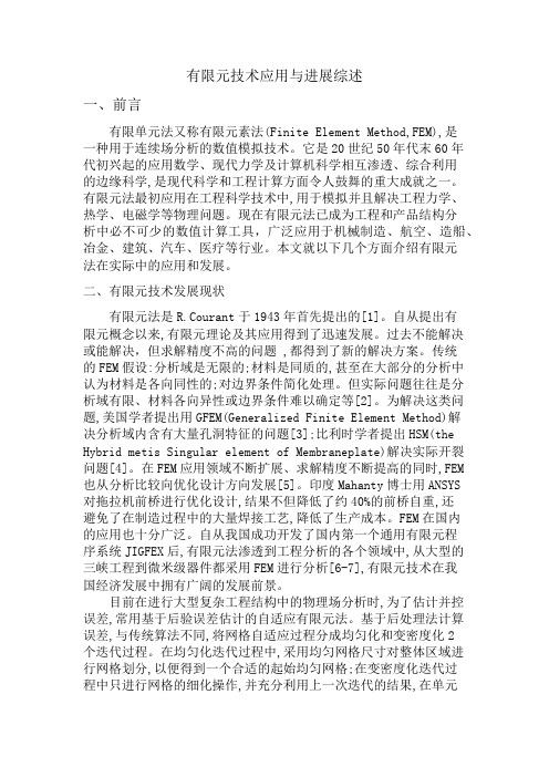
有限元技术应用与进展综述一、前言有限单元法又称有限元素法(Finite Element Method,FEM),是一种用于连续场分析的数值模拟技术。
它是20世纪50年代末60年代初兴起的应用数学、现代力学及计算机科学相互渗透、综合利用的边缘科学,是现代科学和工程计算方面令人鼓舞的重大成就之一。
有限元法最初应用在工程科学技术中,用于模拟并且解决工程力学、热学、电磁学等物理问题。
现在有限元法已成为工程和产品结构分析中必不可少的数值计算工具,广泛应用于机械制造、航空、造船、冶金、建筑、汽车、医疗等行业。
本文就以下几个方面介绍有限元法在实际中的应用和发展。
二、有限元技术发展现状有限元法是R.Courant于1943年首先提出的[1]。
自从提出有限元概念以来,有限元理论及其应用得到了迅速发展。
过去不能解决或能解决,但求解精度不高的问题 ,都得到了新的解决方案。
传统的FEM假设:分析域是无限的;材料是同质的,甚至在大部分的分析中认为材料是各向同性的;对边界条件简化处理。
但实际问题往往是分析域有限、材料各向异性或边界条件难以确定等[2]。
为解决这类问题,美国学者提出用GFEM(Generalized Finite Element Method)解决分析域内含有大量孔洞特征的问题[3];比利时学者提出HSM(the Hybrid metis Singular element of Membraneplate)解决实际开裂问题[4]。
在FEM应用领域不断扩展、求解精度不断提高的同时,FEM 也从分析比较向优化设计方向发展[5]。
印度Mahanty博士用ANSYS 对拖拉机前桥进行优化设计,结果不但降低了约40%的前桥自重,还避免了在制造过程中的大量焊接工艺,降低了生产成本。
FEM在国内的应用也十分广泛。
自从我国成功开发了国内第一个通用有限元程序系统JIGFEX后,有限元法渗透到工程分析的各个领域中,从大型的三峡工程到微米级器件都采用FEM进行分析[6-7],有限元技术在我国经济发展中拥有广阔的发展前景。
- 1、下载文档前请自行甄别文档内容的完整性,平台不提供额外的编辑、内容补充、找答案等附加服务。
- 2、"仅部分预览"的文档,不可在线预览部分如存在完整性等问题,可反馈申请退款(可完整预览的文档不适用该条件!)。
- 3、如文档侵犯您的权益,请联系客服反馈,我们会尽快为您处理(人工客服工作时间:9:00-18:30)。
附录B.英文文献There are many types of CAE technology, including the finite element method, boundary element method, finite difference method. Each method has its own application areas, of which the application of finite element method more and more areas, has been used in structural mechanics, structural dynamics, thermodynamics, fluid mechanics, circuit theory, electromagnetism and so on.ANSYS software is the financial structure, fluid, electric field, magnetic field, acoustic field analysis in one large-scale finite element analysis software. By the world's largest finite element analysis software ANSYS, one of the United States developed it with most CAD software interface for data sharing and exchange, such as Pro / Engineer, NASTRAN, Alogor, I-DEAS, AutoCAD, are modern Advanced CAE product design tools.ANSYS finite element package is a multi-purpose finite element method for computer design program, can be used to solve the structure, fluid, electricity, electromagnetic fields and collision issues. So it can be applied to the following industries: aerospace, automotive, biomedical, bridges, construction, electronics, heavy machinery, micro-electromechanical systems, sports equipment, etc..Finite Element Analysis (FEA,Finite Element Analysis) of the basic concept is tore-place the relatively simple problem to solve complex problems later. As it will solve the do-main is composed of many small-called finite element subdomain interconnection compone-nts,assuming that each unit of an appropriate (relatively simple) approximate solution,and then derived the general solution of the domain satisfy the conditions (such as balanced con-ditions),thus the solution of the problem. This solution is not exact solutions,but appro-ximate solution,since the actual problem is relatively simple to replace the problem. Since most practical problems it is difficult to be accurate solution,while finite element is not only high accuracy but also to adapt to a variety of complex shapes,thereby becoming an effective means of engineering analysis.FEM together those who are able to express the actual domain for the discrete element. The concept of the finite element as early as several centuries ago and have been applied,for example,polygon (a finite number of straight-line unit) to get close to circle thecir-cumference of a circle,but as a way to be made,it is the most recent matter. Finite ele-ment method was originally known as the matrix approximation method,the structural strength of aircraft used in the calculation,and because of its convenience,practicality and effectiveness arising from research scientists to engage in mechanical interest. Through the efforts of just a few decades,with the rapid development of computer technology and the popularity of the finite element method in structural engineering fromthe intensity of the rapid analysis extended to almost all areas of science and technology,become a rich and colorful,practical and efficient application of a wide range of numerical analysis.Finite element method with other methods of solving the boundary value problemsimil-ar to the fundamental difference is that the approximation of it is limited to relatively small sub-domain. 60 In the early 20th century structure was first proposed the concept of the finite element calculation of Clough (Clough),Professor vividly describes as: "The finite element method + = Rayleigh Ritz method piecewise function",that is,the finite element method is the Rayleigh Ritz method a localized situation. Different from the solution of (often difficult) to satisfy the boundary conditions of the definition of domain function to allow the Rayleigh Ritz method,finite element method will be defined in a simple function of geometry (such as two-dimensional problem of arbitrary quadrilateral or triangle) on the unit domain ( piecewise function),the definition does not consider the whole domain of the complex boundary conditions,this is the finite element method is superior to other similar methods of one of the reasons why.Different physical properties and mathematical models of the problem,finite element method to solve the basic steps are the same,only the specific formula to solve a different derivation and computation. Finite Element Analysis of the basic steps are as follows: The first step: the definition of the problem and solution domain: In accordance with the actual problem solving domain approximation to determine the physical properties and geometry of the region.The second step: Solving domain discretization: The approximate solution of the domain with different size and shape of a limited and linked to each other unit,composed of afin-ite number of discrete domains,the habit of division as the finite element network. Obvio-usly the smaller the unit (the finer t he network) is similar to the level of discrete domain,the better,the more accurate results,but the calculation of the volume and error will be larger,so to solve the discrete domain is the finite element method,one of the core tech-nology.The third step: to determine the state variables and control method: a specific physical problem can usually be handled by a group of state variables include the issue of boundary conditions that the differential equations for the finite element for solving differentialequa-tions are usually translated into the functional equivalent forms of .Step four: unit derived: on the unit to construct a suitable approximate solution,that is derived out of the finite element type,including a reasonable choice of coordinate system units,the establishment of unit test function,to one way or another unit of the stateva-riables given the discrete relations to form the unit matrix (the structure of said mechani-cal stiffness or flexibility matrix array).In order to ensure the convergence of problem solving,there are many principlesde-rived units to follow. In terms of engineering applications,it is important to payatten-tion to each unit of problem-solving performance and constraints. For example,the unit should be based on the rules for shape,and deformed not only low-precision,but also the risk of missing rank,will result in failure to solve.Step five: Solution assembly: assembly to form a discrete unit of the total domain matrix equation (Joint equations),reflecting the approximate solution of the discrete domain the request domain,that is,the continuity of function modules to meet the conditions for cer-tain. Assembly unit in the adjacent node,the state variables and their derivatives (if possib-le) to establish continuity in the junction point.Sixth step: solving simultaneous equations and the results of the interpretation: the finite element method eventually lead to simultaneous equations. Simultaneous equations can be used to solve the direct method,the election law and the random generation method. Solv-ing a result,the state Department unit node approximation variables. The results for the quality and design guidelines will be provided to allow values to evaluate and determine the need for double-counting.In short,the finite element analysis can be divided into three stages,pre-treatment,processing and post-processing. Pre-processing finite element model is built to complete the unit mesh; post-processing is the acquisition and processing the results of the analysis,a-lows users to extract information easy to understand results.In practice,the finite element method is usually composed of three main steps:1,pre-processing: the user object to be analyzed to establish part of the model,in this model,the geometry of the part being cut into several discrete sub-region - otherwise known as "modules." In some of the modules referred to as "nodes" of the discrete points connected with each other. Some of these nodes are fixed displacement,while the remaining loads are given. Prepare such a model could be extremely time-consuming process is why the commercial competition between the lies: how to use the most friendly graphical inter-face of the "pre-processing module",to help users complete the tedious work of boring. Some pre-processing module as a computerized drawing and an integral part of the de-ign process,can be pre-existing CAD file grid coverage,which can be easily completed by Finite Element Analysis.2,Analysis: the pre-processing module prepared data into finite element program,andthus constitutes a solution of linear or nonlinear system of algebraic equations thatKij * Uj = FiWhere u and f,respectively,for each node of the displacement and the role of external forces. Matrix form of K depend on the type of problem solving,the module will outline the truss with the linear elastic stress analysis. Business procedures may carry a very large library,the different types of unit s applicable to a wide range of various problems. Finite element method is one of the main advantages of: Many different types of problems are available to deal with the same procedure,the difference is only specified from the cell library for the problem in different cell types.3,post-processing: In the early finite element analysis,users need to carefully study the procedures for computing a large number of figures after,that is,the model set out in the discrete position of the displacement and stress. This method is easy to miss important trends and hot spots,and the latest graphics processing to be use to help the usercom-puting the results of direct observation. Typical post-processing module can display the model across the color line graph of stress for different stress levels,indicating the entire stress field is similar to the images or Photoelasticity moire results.附录C.中文翻译CAE的技术种类有很多,其中包括有限元法,边界元法,有限差法等。