西玛Z4系列直流电机
ZKZ-4S 说明书

ZKZ-4S 说明书
ZKZ-4型转速监控装置外接转速脉冲传感器、或残压实时监测水轮发电机组的转速,并在机组各转速点输出开关量信号和与机组转速对应的模拟量信号,为自动开、停机及电厂监控系统服务。
技术参数装置故障报警信号:1路,装置异常时接点闭合。
模拟量输出:420mA(对应于机组转速0Ne200Ne)modbus-RTU。
通讯:机组频率和各报警点输出。
输出接点容量:250VAC,30VDC。
工作环境:温度0-50℃湿度<85%。
外形尺寸:盘装484×320×134mm。
电源:DC220V或AC220V/50Hz,DC110V。
任选功耗:50W。
工作原理ZKZ-4转速监控装置由齿盘、传感器及PLC监控装置本体组成。
PLC系统采用S7-200系列,经内部分频后产生测量定时脉冲,周期为50us,其测量精度可达0.01Hz,稳定性高,不变。
显示电路采用高亮度LED动态显示方案。
信号输入回路有光电隔离。
将信号周期取入PLC内,再换算成对应的频率、转速百分比及zui大值等内容提供显示、记忆。
多路输出信号经过放大后驱动继电器输出,其中10个动作点与所设定的转速百分比对应,测转速达到设定值时,对应输出接点动作。
装置采用稳态开关电源,交、直流均可稳定工作,且电压变化不影响测控装置可靠工作。
高压电机使用维护说明书

IEC34--6 中规定了旋转电机的各种冷却回路及冷却方式。三相异步电动机通常采用以下的冷却 方式:IC01、IC11、IC21、IC31、IC37、IC81W、IC141、IC151、IC611。 常用冷却方式标志的含义:IC01--自冷开启式,风扇装在轴上
IC611--全封闭扇冷自通风,电机上面装有热交换器(空气对空气) IC81W--空冷自通风电机上面装有热交换器(空气对水) ,水循环由独立
的水泵或水系统供给动力 1.2.4 旋转方向
当电动机线端标志的字母顺序(U、V、W 或 U1、V1、W1)与电源相序的字母顺序(A、B、C)相 同时,由主轴伸端视之为顺时针方向;任意互换两相接线,电机便可改为逆时针旋转。
高压三相异步电动机
使用维护说明书
编制: 校核: 会签: 审定: 批准:
西安西玛电机(集团)股份有限公司
目
录
1. 引言…………………………………………………………………………(2) 1.1 概述…………………………………………………………………………(2) 1.2 一般说明……………………………………………………………………(2) 2. 安装与调整……………………………………………………………………(2) 2.1 收货与搬运…………………………………………………………………(2) 2.2 贮存…………………………………………………………………………(2) 2.3 拆箱…………………………………………………………………………(3) 2.4 安装前的准备………………………………………………………………(3) 2.5 定位…………………………………………………………………………(3) 2.6 基础…………………………………………………………………………(3) 2.7 安装程序……………………………………………………………………(3) 2.8 电气检测……………………………………………………………………(4) 3. 电气连接及起动………………………………………………………………(4) 3.1 连接和整定…………………………………………………………………(4) 3.2 初次起动—不对接…………………………………………………………(4) 3.3 初次起动—与负载对接……………………………………………………(5) 3.4 起动次数……………………………………………………………………(6) 3.5 停止使用时的维护…………………………………………………………(6) 4. 检查及维护……………………………………………………………………(6) 4.1 电动机运行时检查…………………………………………………………(6) 4.2 轴承维护……………………………………………………………………(6) 4.3 油的更换……………………………………………………………………(6) 4.4 轴承温度限值………………………………………………………………(7) 4.5 炭粉的清理…………………………………………………………………(7) 4.6 冷却器的清理………………………………………………………………(7) 5. 附件……………………………………………………………………………(7) 5.1 加热器………………………………………………………………………(7) 5.2 测温元件……………………………………………………………………(7) 5.3 冲击波保护装置……………………………………………………………(7) 6. 故障排除………………………………………………………………………(7) 6.1 电动机不能起动……………………………………………………………(7) 6.2 轴承发热……………………………………………………………………(8) 6.3 漏油…………………………………………………………………………(8) 6.4 振动、噪声…………………………………………………………………(8) 6.5 绝缘电阻低…………………………………………………………………(8) 6.6 电动机过热…………………………………………………………………(9) 7. 异步电动机的允许温升………………………………………………………(9) 附录:电机的干燥处理……………………………………………………………(10)
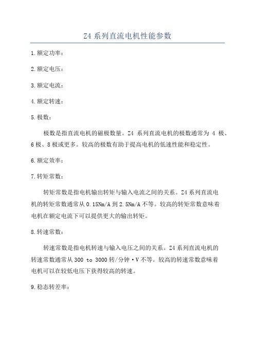
Z4系列直流电机性能参数
Z4系列直流电机性能参数
1.额定功率:
2.额定电压:
3.额定电流:
4.额定转速:
5.极数:
极数是指直流电机的磁极数量。
Z4系列直流电机的极数通常为4极、6极、8极或更多。
较高的极数有助于提高电机的低速性能和稳定性。
6.额定效率:
7.转矩常数:
转矩常数是指电机输出转矩与输入电流之间的关系。
Z4系列直流电
机的转矩常数通常从0.15Nm/A到2.5Nm/A不等。
较高的转矩常数意味着
电机在额定电流下可以提供更大的输出转矩。
8.转速常数:
转速常数是指电机转速与输入电压之间的关系。
Z4系列直流电机的
转速常数通常从300 to 3000转/分钟·V不等。
较高的转速常数意味着
电机可以在较低电压下获得较高的转速。
9.稳态转差率:
稳态转差率是指电机额定转速和无负载转速之间的差异。
Z4系列直流电机的稳态转差率通常为0.5%到1%,较低的转差率意味着电机在额定负载下具有更好的稳定性。
10.起动转矩:
起动转矩是指电机在启动过程中产生的最大输出转矩。
Z4系列直流电机的起动转矩通常为额定转矩的2到3倍,可以确保电机在起动时具有足够的力矩。
总之,Z4系列直流电机具有广泛的额定功率范围、额定电压、额定转速、转矩常数等性能参数,在工业领域中广泛应用,具有高性能和高可靠性的特点。
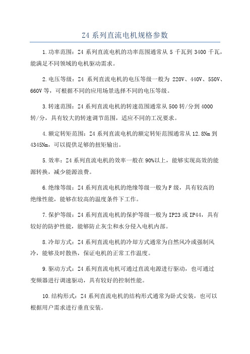
Z4系列直流电机规格参数
Z4系列直流电机规格参数
1.功率范围:Z4系列直流电机的功率范围通常从5千瓦到3400千瓦,能满足不同领域的电机驱动需求。
2.电压等级:Z4系列直流电机的电压等级一般为220V、440V、550V、660V等,可根据不同的应用场景选择不同的电压等级。
3.转速范围:Z4系列直流电机的转速范围通常从500转/分到4000
转/分,具有较大的转速调节范围,适应不同的工况要求。
4.额定转矩范围:Z4系列直流电机的额定转矩范围通常从12.8Nm到4345Nm,可以提供足够的扭矩输出。
5.效率:Z4系列直流电机的效率一般在90%以上,能够实现高效的能
源转换,减少能源浪费。
6.绝缘等级:Z4系列直流电机的绝缘等级一般为F级,具有较高的
绝缘性能,能够在较高的温度条件下工作。
7.保护等级:Z4系列直流电机的保护等级一般为IP23或IP44,具有
较好的防护性能,能够防止灰尘和水分侵入电机内部。
8.冷却方式:Z4系列直流电机的冷却方式通常为自然风冷或强制风冷,能够及时散热,保证电机的正常工作温度。
9.驱动方式:Z4系列直流电机可通过直流电源进行驱动,也可通过
变频器进行调速驱动,具有较好的控制性能。
10.结构形式:Z4系列直流电机的结构形式通常为卧式安装,也可以
根据用户需求进行垂直安装。
11.使用环境:Z4系列直流电机适用于室内环境,通常使用温度在0℃至40℃之间。
总体来说,Z4系列直流电机是一种性能可靠、功率较大的电动机,
具有较高的效率和转速调节范围,适用于各种工业领域的电机驱动需求。
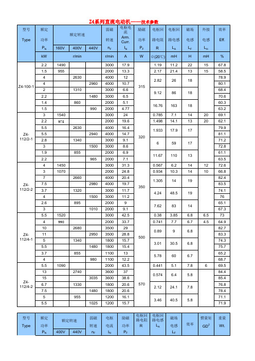
Z4系列直流电机规格参数

mH 5.3 18.9 37.5 3.65 13.5 26 3.4 9.8 19.4 3.15 10.4 2.7 17.7 2.07 8.3 15.2 5.8 17.6 25 1.16 4.65 9.3 15.7
% 85 85.9 79.4 80.9 71.9 74.5 87.8 88.3 81.2 83.4 75.6 77.7 88.2 88.6 83.6 84.7 79.4 80.5 87.4 88.5 80.4 82.6 88.2 89.1 77.9 79.4 89.1 90.2 84.7 85.7 79.1 81.7 84.7 86.5 75.5 78.1 73 74.1 89.5 90.7 85.8 87 82.2 83.7 77.3 79.7
1.72
350
型号 Z4-180Type 22/21
额定 功率 PN kW 16.5 18.5 33
额定转速 400V 440V
弱磁 转速 nF r/min 1600 2000 1250 3200 3000 2000 3000 2000 1600 1000 3000 1000 3200 2800 2000 1400 1200 750 3000 2000 1300 1200 1000
Z4-132-1
650
1.309 2.56 0.226
0.32
140
Z4-132-2
73C
0.811 1.565 0.1905
0.4
Байду номын сангаас160
Z4-132-3
800
0.531 0.976 0.1835
0.48
180
Z4-16011
37 19.5 22 40.5
820 58.8 113 920 50.5 137 77.8 59.1 95.4 51.4 42.4 185 115 79 61 1400 1200 1050 0.862 0.097 0.376 0.675 0.29 0.947 1.264 0.0555 0.2125 0.419 0.756 0.593 0.1426
YBX4样本

佳木斯电机股份有限公司技术文件0EE.138.295-2016YBX4系列高效率隔爆型三相异步电动机产品样本(机座号80~355)2016-07-30发布2016-07-30实施佳木斯电机股份有限公司发布YBX4系列高效率隔爆型三相异步电动机产品样本(机座号80~355)1概述YBX4系列高效率隔爆型三相异步电动机是我公司自主开发设计的全封闭式高效率隔爆型三相异步电动机。
效率指标符合GB 18613-2012《中小型三相异步电动机能效限定值及能效等级》中1级电动机节能评价值的规定。
是目前全球范围内最高效率的三相异步电动机,也是三相异步电动机中的高端产品。
本系列电动机符合国家标准GB 3836.1《爆炸性环境第1部分:通用要求》和GB 3836.2《爆炸性环境第2部分:由隔爆外壳“d”保护的设备》的规定。
本系列电动机制成隔爆型,适用于爆炸性气体环境中机械设备的电力驱动。
防爆标志为ExdⅠMb,ExdIIAT(1-4) Gb,ExdIIBT(1-4)Gb,ExdIICT(1-4)Gb ,温度组别为T1、T2、T3、T4。
本系列电动机机座号范围为80~355,功率等级和安装尺寸符合GB/T4772.1/IEC 60072-1和GB/T4772.2/ IEC 60072-2标准的规定。
2产品特点YBX4系列电动机整体外观(见图1)。
图1 整体外观图产品主要有以下特点:a) 电动机主接线盒位于机座的顶部,可以左右旋转满足用户不同出线方式的要求;b)机座号H160及以上电机,可以根据用户需要提供定子测温装置(可选PTC或PT100)、轴承测温装置(PT100)、加热器、不停机注排油装置;c) 机座号H225及以上电机,可根据用户需要提供底脚调整螺栓孔;d) 接线盒、机座、端盖和风罩的外形美观、样式新颖,并且有利于降噪和通风;e) 电动机采用热分级为155级(可选180级)绝缘系统,从而延长电机的使用寿命;f) 电动机工作制为S1,冷却方式为IC411,外壳防护等级为IP55;g) 适用于各种应用场合,如:“W”、“TH”、“WTH”、“F1”、“F2”、“WF1”及“WF2”,其中:W为户外防轻腐蚀型;TH为湿热带;WTH为户外湿热带;F1为户内防中等防腐型;F2为户内防强腐蚀型;WF1为户外防中等腐蚀型;WF2为户外防强腐蚀型;h)电动机机座底部安装有防爆呼吸排水阀(卧式安装方式时);i)机座号80~180的2P、4 P、6 P、8P电机采用铸铜转子或者铜条转子,其它机座号电机采用铸铝转子;j) 电动机的高质量保证了高的运行可靠性;k)为了方便连接负载,在电动机轴伸端面均预留有C型中心孔(见表1)。
西玛NR133XD型潜水电机使用说明书

NR133XD SAFETY PRECAUTIONSFor the best results with submersible motors, read this manualand all of the warning sign attached to the motor carefully beforeinstalling and operating it, or maintaining and testing it, andfollow the instructions exactly.In this manual, the rank of cautions is distinguished as WARNINGand CAUTION.Indicates a potentially hazardous situationmay happen, which, if not avoided, can resultin death or serious injury.Indicates a potentially hazardous situationmay happen, which, if not avoided, can resultin injury or damage of product.users for quick reference.This motor is intended for installation bytechnically qualified personnel.Verify motor is filled with clean water beforeinstalling. The warranty is void if this is not done.This motor and lead assembly are designedonly for use submerged in water.lead wires should be protected during storage, handling,moving and installation of the motor.2) I nspect the motor to determine that it is the correct HP, voltageand size for the job and that there is no shipping damage.3) T he factory-installed water in the motor is supplied withPropylene Glycol capable of temperatures to -30°C(-22°F).Do not install, transport or store below these temperatures. Ifstorage is necessary below these temperatures, drain the waterfrom the motor.4) A fter long periods of idleness and on all new installations, checkthe electrical resistance and megger the motor with lead wiresconnected: see table A. Prior to installation, the motor should havean insulation value of at least 50 megohms. After installation,motor and power cable should have a minimum insulation valueof 1 megohm. If minimum values are not obtained, contact factory.5) C heck the tightness of drain plugs, mounting bolts and cableconnections.6) D o not hammer the shaft, coupling or slinger since this maydamage the thrust bearing. Check the rotation of the shaft byhand to insure that it turns freely.7) D o not drop the bottom end of the motor in the dirt or mudsince this may plug up the diaphragm opening.8) I f motor is to be installed in a horizontal position, make surethat the lead wires are at the 12 o'clock position when facingthe motor shaft (in horizontal position).TROUBLE SHOOTING OF SUBMERSIBLE MOTORS1) Motor does not start.• No power supply.→ Check for loose or corroded connectionsand motor lead terminals.• Defective connections. → Correct connections.2) Fuses or relay blow when motor starts.• Incorrect voltage. → Apply correct voltage (Nameplate).• Incorrect fuses or relay.→ Replace with proper fuses and relay.• Defective capacitors. → Replace with proper capacitors.• Wrong connections. → Correct wrong connections or shortcircuit.• Locked rotor conditions. →Correct pump or well conditions.• Insulation resistance down. →Check the line and correct.3) Motor runs for a while and then blown fuses or relay.• Low voltage or high voltage. → Apply rated voltage.• Defective capacitors. → Replace with proper capacitors.• Different control box for the motor. → Replace with propercontrol box.• Defective starting voltage relay. → Replace with proper relay.• Pump is sand clogged. → Pull pump and clean well.• Overheated protector. → Shield the control box from heatsource.The following conditions are stated to provide the owner with a listof criteria for maximum motor life and to assure motor warranty.PRE-INSTALLATION1) Maximum water temperature:A) 35°C( 95°F): 6" (5 40HP) motors.B) 25°C( 77°F): 6" (50,60HP), 8", 10", 12" and 14" motors.2) PH content of the water between: 6.5 -83) Maximum chlorine content: 500 PPMMaximum Sulfuric acid iron content: 15 PPMMaximum Fluorine content: 0.8 PPMMaximum Electric conductivity: 118 μMHO/INCH4) Maximum sand content: 50 PPM5) Proper approved three-phase overload protection. See TABLE B.6) Proper fusing for motor circuit protection. See TABLE C.7) Proper line voltage variation during running conditions:60Hz: 460V, 230V ±10% , 50Hz: 380V ±10%at motor lead terminal.(voltage drop of cable should be considered by user.)Combination of voltage and frequency variation: ±10%(sum of absolute values of voltage and frequency)Current unbalance between legs should not exceed 5% of theaverage.8) Proper sizing of motor HP. (current, thrust, voltage, etc.)9) Motor must be set with minimum 10 feet clearance from thebottom of the well.H I TACH I SUBMERS I BLE MOTORSF1Date: 03/22/16Supersedes: 09/01/0710) In the case of horizontal installation, the motor is to be rigidlyaligned with the pump and firmly mounted to prevent any load on the shaft and bearings and to avoid any damaging vibrations to the motor.11) The motor must always be immersed in water so that a flowvelocity of cooling water at a rate of 0.5 feet per second flows past any and all parts of the motor. The motor will not operate in mud or sand.12) Hitachi motor leads are sized for operation while submergedin water at the maximum rated ambient water temperature.The factory motor leads must be fully submerged at all times during operation to avoid damage or failure.13) The power cables shall be sized large enough so that at ratedcurrent there will be less than a 5% voltage drop. See TABLEC. Cables must be waterproof submersible type.14) For three-phase motors a balanced and properly sizedtransformer bank shall be provided. Improper electrical supply (for example, phase converter, V-connection transformer, etc.) or connections will void the warranty.15) Single-phase protection is recommended for protection of theinstallation. Any failure due to single phasing of the incoming voltage causing the motor to fail will void the warranty.16) Surge suppressors are recommended in the interest ofprotecting the control panel, as well as the insulation system of the motor. Any motor failure due to lightning or other natural disasters will void the warranty.17) Provide waterproof insulation splices between all lead wiresand well cables.18) In the event that a reduced voltage starter is used to start themotor, the following should be verified:A. Correct quick trip, class 10 or better, ambient compensatedoverloads are incorporated.B. Proper short circuit protection is utilized.C. The torque required by the motor and pump package isattainable by this type starter.D. The lead arrangement of the motor is acceptable with theproposed starter load connections.E. Verify that if any time delay relays are used in switchingcontactors in and out, that the time settings do not exceed 2 seconds; this could damage the motor.F. If a manual auto-transformer starter is used, voltage shouldbe minimum 60% of rated voltage, and switched to "Run"condition within 2 seconds. Double check TABLE B and C for correct protection.19) Single-Phase Motors (5-15HP)Proper connections and correct capacitors and relays are necessary for single-phase motor starting and running.Connection diagram: See Fig. 1.Performance and recommendable capacitors: See TABLE D.20) VFD (Inverter)Please contact Hitachi for VFD(inverter) usage on Hitachi Submersible MotorsMAINTENANCEThere are no bearings that need oil or grease. The motor, being inaccessible, should be monitored through its electrical connections.1) Measure and record operating current and voltage.2) Measure and record the motor insulation resistance. Anyresistance of less than 50 megohm for a new motor should be evaluated or checked further by a qualified service shop.3) Lightning arrestors and/or surge capacitors will help preventdamage to the control box, cables, and motor.4) Single-phase protection will help in preventing motor failuredue to adverse incoming primary power.5) Based on the values obtained in A and B above and the outputflow rates and pressures of the pump, a complete picture of total performance can be obtained. This can be used to determine any pump and motor maintenance and overhauling which might be required.6) If the motor is to be stored, protect the unit from freezing bystoring in an area with a temperature higher that -30°C(-22° F). OPERATION1) After energizing the motor, check the flow and pressure of thepump to make sure that the motor is rotating in the correct direction. To correct a wrong rotation, switch any two of the three cable connections. (Three-phase motor only)2) When starting the pump for the first time, inspect the waterfor sand. If sand appears, then continue to pump till the water clears up; otherwise, sand will accumulate in the pump stages and will bind or freeze the moving parts if water is allowed to flow back down the well.3) During testing or checking rotation (such as "bumping" or "inching")the number of "starts" should be limited to 3, followed by a full15 minutes cooling-off period before any additional "starts" areattempted. Depending on the depth of the well and/or method of checking, these rotational checks or "starts" may actually be full-fledged starts. If this is the case, then a full cooling-off period of 15minutes is required between this type of start.4) For automatic (pilot device) operation, the motor should beallowed to cool for 15 minutes between starts.5) Input voltage, current and insulation resistance values shouldbe recorded throughout the life of the installation and should be used as a from of preventive maintenance.TABLE A. RESISTANCE DATASingle Phase 2 Pole 230V/60HzMOTORSIZE & TYPEHPRESISTANCE ( )R Y B Y R B6”, C5 2.1430.482 2.597”7.5 1.3720.371 1.715”10 1.0220.286 1.280”150.6480.2000.821Three Phase 2 Pole Three Phase 4 PoleMOTORSIZE & TYPEHP VOLTRESISTANCE( )MOTORSIZE & TYPEHP VOLTRESISTANCE( ) 6”, C52300.7768”, W7.52300.564”5460 3.021”7.5460 2.178”7.52300.621”102300.564”7.5460 2.400”10460 2.178”102300.418”152300.399”10460 1.590”15460 1.519”152300.282”202300.399”15460 1.044”20460 1.519”202300.229”252300.242”204600.832”254600.888”252300.180”302300.242”254600.636”304600.888”302300.14710”, W404600.408”304600.530”50”0.408”404600.358”60”0.288”50”0.308”75”0.257”60”0.308”100”0.1718" , C40”0.278”125”0.171”50”0.20212”, W150”0.138”60”0.202”175”0.1198”, W40”0.372”200”0.0826”50”0.33114”, W250”0.0552”60”0.278”300”0.0517”75”0.218Values are for normal temp.68°F (20 ) andwith motor lead wires resistance.LEAD WIRE COLORR: Red , Y: Yellow, B: Black , G: Green (6"C , 8"C)MOTOR TYPEC : CANNED , W : WATER TIGHT”100”0.164”125”0.132”150”0.11510”, W175”0.121”200”0.0929”250”0.077612”, W300”0.0386TABLE B. SELECTION TABLE OF OVERLOAD PROTECTION TABLE C. FUSE AND COPPER CONDUCTIOR CABLEPhaseMOTORSize & TypePoleHP V olts HzAMPSOverloadProtection FUSECopper Cable Size from Control Box to MOTOR (FEET)Conductor Size AWG,MCM COND.TEMP 80 RatedAMPSS.F=1.15AMPSSTARTERSizeHEATER CODE(FurnasP.)STDSizeDual-ElementSize121086420000000000250300350400500600Three Phase6”, C2Pole52306015171K58453024038061097015002380460607.58.50K43251596015202420380509 0K493017.56701060167026907.52306022261K6470401602604106501010161024304606011131K5435206601050167026603805013 1K554025450710113018002790102306029331-3/4K689060200320500780124018804606014.516.51K584530490780125019903805017 1K58603034054085013602110152306042462K74150802103405308401270159020204606021231-3/4K637040340540860137021203805025 1-3/4K64804536058092014302260202306054602-1/2K771751002604006409701220155019404606027302K6790504106501040162025703805032 2K6910060280440710109017402620252306068763K832251253305207809801240156018004606034382K7211060530840130020603805041 2K731258035055086013702060302306082943K862501504306508101030130014901790 4606041472-1/2K74125804306901070170025703805048 2-1/2K7515090300480740117017702220404606053603K76175100520810129019403805062 3K76200125360560890135017002150504606070793K832251256501030156019603805083 3K852501504406901040131016602090604606082943-1/2K862501508501290161020508”, C2Pole404606054613K76175100520810128019303805064 3K77200125360550870132016602100504606067753K782251256701060160020103805078 3K852501504507101070135017102150604606079893-1/2K862501508601310164020803805094 3-1/2K8730017559088011101410177020408”, W2Pole404606056633K76175100520810128019303805065 3K77200125360550870132016602100504606065733K782001256701060160020103805078 3K852501504507101070135017102150604606080903-1/2K862501508601310164020803805095 3-1/2K873001755908801110141017702040 7546060961093-1/2K88300175710108013601720216038050115 4K893502254807309101160146016802010 100460601271454K92400225810102013001630188038050152 4-1/2K265003005506908701100127015101760 125460601611804-1/2K285003008201040131015101800 38050192 4-1/2K2860035070088010201220142016202030 150460601972204-1/2K316003501090125015001750 38050235 5K327004507408501010118013501690203010”, W2Pole175460602052305K317004009501090130015201740 38050261 6K23800500700840970111013901670 200460602352705K338004501130132015101889 38050295 6K24900600870100012501500 250460602953406K27900600121015101810 38050370 6K2812006509901190 12”, W2Pole300460603503966K29120065012701520 38050420 6K31130075010508”, W4Pole7.52306026291-3/4K6880502704206701050166025104606013141K564025670106016902700102306032361-3/4K7010060200310500770123018504606016181K60503049078012501990152306046522-1/2K75150903405208301250157019904606023261-3/4K64704533053084013402080202306058662-1/2K771751102503906109301160148018604606029332K699060390620100015402450252306076863K852501503205107709701230154017804606038432K7312570520830128020403023060881003K873001754206408001010127014701760 4606044502-1/2K751508043068010601680254010”, W4Pole404606062713K77200110830131019802490504606073833K832251506701060159020006046060911043-1/2K8730017589013501690215075460601061213-1/2K893502001090137017402190100460601451664-1/2K2645030010201300164018802250125460601752004-1/2K296003501030130014901790208012”, W4Pole150460601902184-1/2K2960035011001270151017602020175460602202505K3270040011001310153017502190 200460602552936K248004501150133015301910 14”, W4Pole250460603053506K271000600123015401850 300460603704256K2912006501550Single Phase 6”, C2Pole5230602427.5804519030047073011707.52306036411107019030047075011301023060505817590220340550830104015230607285225150240380570720920Recommended Adjustable Overload RelaysSiemens : Class/Type 3UA5,3UA6,3UA7Furnas : Class/Type US/15 48AG,UA/15 48BGTABLE D. PERFORMANCE DATA OF SINGLE-PHASE SUBMERSIBLE MOTOR2P FOR 6” DEEP WELLOutput(HP)57.51015V oltage-Frequency 230V60Hz230V60Hz230V60Hz230V60HzNo Load Current (A)8.88.312.016.1No Load Loss(W)1184142815442050L o a d C h a r a c t e r i s t i c sLoad(%) 25 50 75 100 125 25 50 75 100 125 25 50 75 100 125 25 50 75 100 125Current (A) 11.5 14.6 18.9 23.8 30.2 13.6 19.5 26.7 35.2 45.6 18.0 25.5 35.5 48.0 59.0 25.5 38.1 52.7 70.8 96.8Ef fi ciency (%) 47.8 66.2 72.2 74.8 72.8 51.1 67.6 72.5 72.9 70.8 54.0 67.8 73.1 73.6 71.5 57.5 70.8 74.7 73.7 69.2Power Factor (%) 73.5 84.0 89.0 91.2 92.3 87.8 92.5 94.5 94.9 94.2 81.8 88.9 91.8 93.2 93.7 82.9 90.2 92.7 93.2 90.8Slip(%) 0.8 1.5 2.2 3.0 4.2 0.8 1.8 2.9 4.2 5.8 0.7 1.7 2.8 4.1 5.6 1.0 2.1 3.3 4.9 7.3Full Load Torque (ft ∙lbs)7.5311.4215.2323Break Down Torque (ft ∙lbs)15.522.027.445Locked Rotor Torque (ft ∙lbs)12.518.321.334Locked Rotor Current (A)124167202275Locked Rotor Code GF E D Rated Input (W)498776751013515180Current of SF 1.15(A)27.5415885Input of SF 1.15(W)573589501183018050Spec. of Running Capacitor 440V AC 440V AC440V AC 440V AC 30μFD 40μFD 50μFD 70μFD Spec. of Starting Capacitor330V AC 330V AC 370V AC 370V AC 200μFD250μFD350μFD450μFDCatalog No. SM-E 186-03R SM-E 186-03R Printed in Japan HF-N(B)。
Z4系列直流电机规格参数
72.2
77.4
88.7
89.6
4.2
530
78.8
80.4
91.7
92.4
88.7
90
85.6
87.4
4.8
580
82.5
84.1
79.6
82
77.5
79.5
87.9
89.4
84.4
86.5
81.2
5
680
84
78.2
80.8
76.5
78.8
型号 Type
Z4-22521
Z4-22531
Z4-25012/11
600 1000 600 3000 1500 750 3000 1000 750 500 1500 600 3000 1500 1000 750 600 500 1500 1000 750 600 500
弱磁 转速
nF r/min 1600 2000 1250 3200 3000 2000 3000 2000 1600 1000 3000 1000 3200 2800 2000 1400 1200 750 3000 2000 1300 1200 1000
5.6
0.0555 1.16 6.9
0.2125 4.65 6.6
1400 0.419 9.3
7.3
0.756 15.7 7.1
效率
惯量矩 GD2
重量 Wt.
%
kg.m2
kg
85
85.9
79.4 0.32 140
80.9
71.9
74.5
87.8
88.3
81.2
0.4
160
83.4
- 1、下载文档前请自行甄别文档内容的完整性,平台不提供额外的编辑、内容补充、找答案等附加服务。
- 2、"仅部分预览"的文档,不可在线预览部分如存在完整性等问题,可反馈申请退款(可完整预览的文档不适用该条件!)。
- 3、如文档侵犯您的权益,请联系客服反馈,我们会尽快为您处理(人工客服工作时间:9:00-18:30)。
摘要:Z4系列直流电机比Z2、Z3系列具有更大的优越性,它不仅可用直流机组电源供电,更适用于静止整流电源供电。
而且转动惯量小,具有较好的动态性能,并能承受较高的负载变化率,特别适用于需要平滑调速、效率高、自动稳速、反应灵敏的控制系统,具有当今国际先进水平。
一、Z4系列直流电机概述:
该机中心高100~355mm是中华人民共和国机械行业标准JB/T6316-92《Z4系列直流电动机技术条件》所规定的标准系列小型直流电动机;中心高400~450mm
为标准系列之外的扩充Z4直流电动机;中心高500~710mm是我厂新开发的中型直流电动机。
本系列电动机可广泛应用于冶金工业轧机、金属切削机床、造纸、染织、印刷、水泥、塑料挤出机械等各类工业部门。
额定电压为160V的电动机,在单相桥式整流器供电的情况下,一般需带电抗器工作,外接电抗器的电感数值在电动机铭牌上注明。
额定电压440V的电动机,均不需外接电抗器。
本系列直流电机性能不仅符合国标GB/T755《旋转电机基本技术要求》,也基本符合德国VDE0530标准。
型号含义:Z4-280-11B,Z表示直流电机,4表示4系列,280表示电机中心高(mm),第一个1表示铁心长度序号,第二个1表示前端盖序号,1为短端盖,2为长端盖,B表示有补偿绕组。
二、Z4系列直流电机结构:
(1)基本结构
Z4系列直流电机采用八角形全叠片结构,不仅空间利用率高,而且当采用静止整流器供电时,能承受脉动电流和快速的负载电流变化。
Z4系列直流电机一般不带串励绕组,适用于需要正、反转的自动控制技术中。
根据用户需要也可以制成带串励绕组。
中心高100~280mm的电动机无补偿绕组,但中心高250mm、280mm的电动机根据具体情况和需要可以制成带补偿绕组,中心高315~450mm的电动机带有补偿绕组。
中心高500~710mm的电动机外形安装尺寸及技术要求均符合IEC国际标准,电机的机械尺寸公差符合ISO国际标准。
(2)冷却方式和结构、安装形式
IC06:自带鼓风机的外通风;
ICl7:冷却空气进口为管道,出口为百叶窗排风;
IC37:即冷却空气进出口均为管道;
IC611:全封闭带空气/空气冷却器;
ICW37A86:全封闭带空气/水冷却器。
并有多种派生形式,如自通风型、带轴向风机型、封闭型、空/空冷却器型等。
各机座号电动机所需冷却风量、风压、及风机电动机功率等数据见表1。
整个系列直流电机的外壳基本防护等级为IP21S
本系列直流电机的安装形式符合GB/T997《电机结构安装型式及代号》的规定,电动机的安装尺寸除底脚孔轴向距离(B尺寸)外,其余尺寸均符合IEC标准。
电机出线盒位置从传动端(非换向器端)视之在机座的右侧(即正盒),如果用户要求出线盒置于机座的另一侧,订货时注明反盒。
电动机基本出轴为单轴伸,面对出线盒(正盒)出轴方向为左出轴。
如用户需要也可以制成双轴伸。
转轴的基本旋转方向从换向器端视之为逆时针旋转。
电动机的传动方式为弹性联轴器联接,也可以用于一定径向力的传动方式(皮带或齿轮传动)。
(3). 电机的附件
根据用户的需要电动机可以设计成能附装测速发电机、脉冲发生器、离心开关以及制动器等的结构形式,具体要求可以与本厂协商。
注:技术数据表中的规格、功率和弱磁调速范围等仅供参考,为了不断地采用新技术、新材料,表中的数据会有变动。
三、Z4系列直流电机常见额定电压和转速
1.直流电机标准额定电压为160V、440V。
也可根据具体情况派生出220V、400V和660V或其他电压。
2.直流电机额定转速有3000、1500、1000、750、600、500、400、300、200 r/min共九档。
减小电枢电压为恒转矩调速,减小励磁电压为恒功率调速。
在额定电压以下用调压调速时为恒转矩。
其最低转速均规定为不低于20 r/min,此时仍能维持额定转矩,转速平稳。
四、Z4系列直流电机使用条件
a.海拔不超过1000m;
b.周围空气温度不大于40℃;
c.工作环境不应有酸性、碱性或其他对绝缘有腐蚀作用的气体;
d.电机z4直流电机为连续工作制(SI);
e. 本系列直流电机采用F级绝缘。
本文来自西玛电机维修员编辑!更多精彩内容尽在。