1-s2.0-S004316481000116X-main[1]
西门子S的基本数据类型
西门⼦S的基本数据类型STEP7中的基本数据类型⑴位(BOOL)位数据的数据类型为BOOL(布尔)型,在软件编程中BOOL变量的值1和0常⽤英语单词TURE(真)和FALSE(假)来表⽰,对应⼆进制数中的“1”和“0”,常⽤于开关量的逻辑运算,存储空间为1位。
⑵字节(BYTE)字节数据长度为8位,数据格式为B#16#,B代表BYTE,表⽰数据长度为⼀个字节(8位),#16#表⽰⼗六进制,取值范围为B#16#0~B#16#FF。
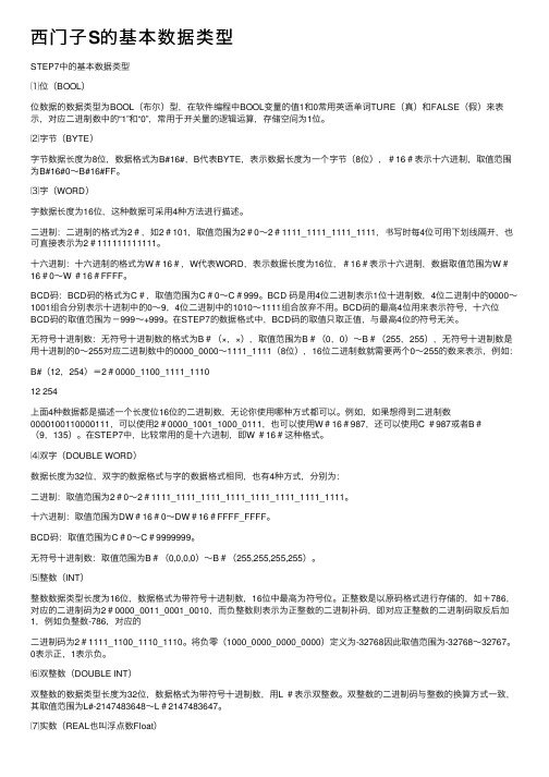
⑶字(WORD)字数据长度为16位,这种数据可采⽤4种⽅法进⾏描述。
⼆进制:⼆进制的格式为2#,如2#101,取值范围为2#0~2#1111_1111_1111_1111,书写时每4位可⽤下划线隔开,也可直接表⽰为2#111111111111。
⼗六进制:⼗六进制的格式为W#16#,W代表WORD,表⽰数据长度为16位,#16#表⽰⼗六进制,数据取值范围为W#16#0~W #16#FFFF。
BCD码:BCD码的格式为C#,取值范围为C#0~C#999。
BCD 码是⽤4位⼆进制表⽰1位⼗进制数,4位⼆进制中的0000~1001组合分别表⽰⼗进制中的0~9,4位⼆进制中的1010~1111组合放弃不⽤。
BCD码的最⾼4位⽤来表⽰符号,⼗六位BCD码的取值范围为-999~+999。
在STEP7的数据格式中,BCD码的取值只取正值,与最⾼4位的符号⽆关。
⽆符号⼗进制数:⽆符号⼗进制数的格式为B#(×,×),取值范围为B#(0,0)~B#(255,255),⽆符号⼗进制数是⽤⼗进制的0~255对应⼆进制数中的0000_0000~1111_1111(8位),16位⼆进制数就需要两个0~255的数来表⽰,例如:B#(12,254)=2#0000_1100_1111_111012 254上⾯4种数据都是描述⼀个长度位16位的⼆进制数,⽆论你使⽤哪种⽅式都可以。
例如,如果想得到⼆进制数0000100110000111,可以使⽤2#0000_1001_1000_0111,也可以使⽤W#16#987,还可以使⽤C #987或者B#(9,135)。
计算机组成原理(第二版)课后题答案
计算机组成原理(第二版)课后题答案第1章计算机系统概论1. 什么是计算机系统、计算机硬件和计算机软件?硬件和软件哪个更重要?解:P3计算机系统:计算机硬件系统和软件系统组成的综合体。
计算机硬件:指计算机中的电子线路和物理装置。
计算机软件:计算机运行所需的程序及相关资料。
硬件和软件在计算机系统中相互依存,缺一不可,因此同样重要。
2. 如何理解计算机的层次结构?答:计算机硬件、系统软件和应用软件构成了计算机系统的三个层次结构。
硬件系统是最内层的,它是整个计算机系统的基础和核心。
系统软件在硬件之外,为用户提供一个基本操作界面。
应用软件在最外层,为用户提供解决具体问题的应用系统界面。
通常将硬件系统之外的其余层称为虚拟机。
各层次之间关系密切,上层是下层的扩展,下层是上层的基础,各层次的划分不是绝对的。
3. 说明高级语言、汇编语言和机器语言的差别及其联系。
答:机器语言是计算机硬件能够直接识别的语言,汇编语言是机器语言的符号表示,高级语言是面向算法的语言。
高级语言编写的程序处于最高层,必须翻译成汇编语言,再汇编程序汇编成机器语言之后才能被执行。
4. 如何理解计算机组成和计算机体系结构?答:计算机体系结构是指那些能够被程序员所见到的计算机系统的属性,如指令系统、数据类型、寻址技术组成及I/O机理等。
计算机组成是指如何实现计算机体系结构所体现的属性,包含对程序员透明的硬件细节,如组成计算机系统的各个功能部件的结构和功能,及相互连接方法等。
5. 冯?诺依曼计算机的特点是什么?解:冯?诺依曼计算机的特点是:P86. 画出计算机硬件组成框图,说明各部件的作用及计算机系统的主要技术指标。
答:计算机硬件组成框图如下:计算机运算器、控制器、存储器、输入设备、输出设备五大部件组成;指令和数据以同同等地位存放于存储器内,并可以按地址访问;指令和数据均用二进制表示;指令操作码、地址码两大部分组成,操作码用来表示操作的性质,地址码用来表示操作数在存储器中的位置;指令在存储器中顺序存放,通常自动顺序取出执行;机器以运算器为中心。
微机原理1-11章答案精简版
第一章习题答案一、单选题1.1946年2月,在美国诞生了世界上第一台计算机,它的名字叫 C 。
A.EDV AC B.EDSAC C.ENIAC D.UNIV AC-I2.在下列描述中属于冯·诺依曼体系结构特点的是 C 。
Ⅰ.采用16进制计数。
Ⅱ.集中而顺序的控制。
Ⅲ.存储程序并且存储时不区别数据和指令。
A.Ⅰ和ⅡB.Ⅰ和ⅢC.Ⅱ和ⅢD.Ⅰ,Ⅱ和Ⅲ3. C 是以CPU为核心,加上存储器、I/O接口和系统总线构成。
A.微处理器B.微型计算机C.微型计算机系统D.单板机4.计算机的字长越长,一个字所能表示的数据精度就越高,在完成同样精度的运算时,则数据处理速度 A 。
A.越高B.越低C.不变D.不一定5.计算机存储数据的最小单位是二进制的 B 。
A.位B.字节C.字长D.千字长6.通常所说的32位机,是指这种计算机的CPU B 。
A.由32个运算器组成的B.能够同时处理32位二进制数C.包含32个寄存器D.一共有32个运算器和控制器二、判断题1.第五代计算机的体积进一步缩小,性能进一步提高,发展了并行技术和多机系统,出现了精简指令集计算机RISC。
( F )2.单片机是把CPU、一定数量的存储器芯片和I/O接口芯片装在一块印刷电路板上,在该板上再配以具有一定功能的输入、输出设备。
(F )3.总线是多个部件间的公共连线,信号可以从多个源部件中的任何一个通过总线传送到多个目的部件。
(T )4.冯·诺伊曼计算机在硬件上是由运算器、控制器、存储器、输入和输出设备5大部分组成。
(T )5.在计算机内部可直接运行二进制数、十进制数、十六进制数。
(F )三、简答题1.简述微处理器的发展概况,从集成度、性能等方面比较各代处理器的特点。
2.简述冯·诺伊曼型计算机的基本组成。
3.名词(概念)简释:微处理器、微型计算机、微型计算机系统、单总线结构、双总线结构、双重总线结构、总线。
4.简述计算机硬件与软件的关系。
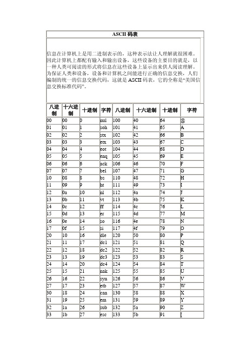
ASCII码对照表
字符
34 35 36 37 40 41 42 43 44 45 46 47 50 51 52 53 54 55 56 57 60 61 62 63 64 65 66 67 70 71 72 73 74 75 76 77
1c 1d 1e 1f 20 21 22 23 24 25 26 27 28 29 2a 2b 2c 2d 2e 2f 30 31 32 33 34 35 36 37 38 39 3a 3b 3c 3d 3e 3f
十六进制 40 41 42 43 44 45 46 47 48 49 4a 4b 4c 4d 4e 4f 50 51 52 53 54 55 56 57 58 59 5a 5b
十进制 64 65 66 67 68 69 70 71 72 73 74 75 76 77 78 79 80 81 82 83 84 85 86 87 88 89 90 91 @ A B C D E F G H I J K L M N O P Q R S T U V W X Y Z [
92 93 94 95 96 97 98 99 100 101 102 103 104 105 106 107 108 109 110 111 112 113 114 115 116 117 118 119 120 121 122 123 124 125 126 127
\ ] ^ _ ' a b c d e f g h i j k l m n o p q r s t u v w x y z { | } ~ del
八进 制 00 01 02 03 04 05 06 07 10 11 12 13 14 15 16 17 20 21 22 23 24 25 26 27 30 31 32 33
十六进 十进制 制 00 0 01 1 02 2 03 3 04 4 05 5 06 6 07 7 08 8 09 9 0a 10 0b 11 0c 12 0d 13 0e 14 0f 15 10 16 11 17 12 18 13 19 14 20 15 21 16 22 17 23 18 24 19 25 1a 26 1b 27
ASCII码值对照表

最全ASCII码对照表ASCII码值对照表ASCII码值ASCII码中英文对照表0010 0000 32 20 空格0010 0001 33 21 !0010 0010 34 22 "0010 0011 35 23 #0010 0100 36 24 $0010 0101 37 25 %0010 0110 38 26 &0010 0111 39 27 '0010 1000 40 28 (0010 1001 41 29 )0010 1010 42 2A *0010 1011 43 2B +0010 1100 44 2C ,0010 1101 45 2D -0010 1110 46 2E .0010 1111 47 2F /0011 0000 48 30 00011 0001 49 31 10011 0010 50 32 20011 0011 51 33 30011 0100 52 34 40011 0101 53 35 50011 0110 54 36 60011 0111 55 37 70011 1000 56 38 80011 1001 57 39 90011 1010 58 3A :0011 1011 59 3B ;0011 1100 60 3C <0011 1101 61 3D =0011 1110 62 3E >0011 1111 63 3F ?0100 0000 64 40 @0100 0001 65 41 A0100 0010 66 42 B0100 0011 67 43 C0100 0100 68 44 D0100 0101 69 45 E0100 0110 70 46 F0100 0111 71 47 G0100 1000 72 48 H0100 1001 73 49 I0100 1010 74 4A J0100 1011 75 4B K0100 1100 76 4C L0100 1101 77 4D M0100 1110 78 4E N0100 1111 79 4F O0101 0000 80 50 P0101 0001 81 51 Q0101 0010 82 52 R0101 0011 83 53 S0101 0100 84 54 T0101 0101 85 55 U0101 0110 86 56 V0101 0111 87 57 W0101 1000 88 58 X0101 1001 89 59 Y0101 1010 90 5A Z 0101 1011 91 5B [ 0101 1100 92 5C \ 0101 1101 93 5D ] 0101 1110 94 5E ^ 0101 1111 95 5F _ 0110 0000 96 60 ` 0110 0001 97 61 a 0110 0010 98 62 b 0110 0011 99 63 c 0110 0100 100 64 d 0110 0101 101 65 e 0110 0110 102 66 f 0110 0111 103 67 g 0110 1000 104 68 h 0110 1001 105 69 i 0110 1010 106 6A j 0110 1011 107 6B k 0110 1100 108 6C l 0110 1101 109 6D m 0110 1110 110 6E n 0110 1111 111 6F o 0111 0000 112 70 p 0111 0001 113 71 q 0111 0010 114 72 r 0111 0011 115 73 s 0111 0100 116 74 t 0111 0101 117 75 u 0111 0110 118 76 v 0111 0111 119 77 w 0111 1000 120 78 x 0111 1001 121 79 y 0111 1010 122 7A z 0111 1011 123 7B { 0111 1100 124 7C | 0111 1101 125 7D } 0111 1110 126 7E ~ 0111 1111 127 7F DEL (delete)删除ESC键 VK_ESCA PE (27)回车键: VK_RETU RN (13) TAB键: VK_TAB(9)Caps Lock键: VK_CAPI TAL (20) Shift键: VK_SHIF T ()Ctrl键: VK_CONT ROL (17) Alt键:VK_MENU (18)空格键: VK_SPAC E (/32)退格键: VK_BACK (8)左徽标键: VK_LWIN (91)右徽标键: VK_LWIN (92)鼠标右键快捷键:VK_APPS (93) Insert键: VK_INSE RT (45) Home键: VK_HOME (36) Page Up: VK_PRIO R (33) PageDow n: VK_NEXT (34)End键: VK_END(35) Delete键: VK_DELE TE (46)方向键(←): VK_LEFT (37)方向键(↑):VK_UP (38)方向键(→): VK_RIGH T (39)方向键(↓): VK_DOWN (40)F1键:VK_F1 (112)F2键:VK_F2 (113)F3键:VK_F3 (114)F4键:VK_F4 (115)F5键:VK_F5 (116)F6键:VK_F6 (117)F7键:VK_F7 (118)F8键:VK_F8 (119)F9键:VK_F9 (120)F10键: VK_F10(121)F11键: VK_F11(122)F12键: VK_F12(123)Num Lock键:VK_NUML OCK (144)小键盘0: VK_NUMP AD0 (96)小键盘1: VK_NUMP AD0 (97)小键盘2: VK_NUMP AD0 (98)小键盘3: VK_NUMP AD0 (99)小键盘4: VK_NUMP AD0 (100)小键盘5: VK_NUMP AD0 (101)小键盘6: VK_NUMP AD0 (102)小键盘7: VK_NUMP AD0 (103)小键盘8: VK_NUMP AD0 (104)小键盘9: VK_NUMP AD0 (105)小键盘.: VK_DECI MAL (110)小键盘*: VK_MULT IPLY (106)小键盘+: VK_MULT IPLY (107)小键盘-: VK_SUBT RACT (109)小键盘/: VK_DIVI DE (111)Pause Break键: VK_PAUS E (19)ScrollLock键: VK_SCRO LL (145)注意:1.在ASCII码中,有4组字符:一组是控制字符,如LF,CR等,其对应ASCI I码值最小;第2组是数字0~9,第3组是大写字母A~Z,第4组是小写字母a~z。
计算机组成原理world版复习题

计算机组成原理期末复习题总结一.数的真值变成机器码时有四种表示方法,即原码表示法,反码表示法,补码表示法,移码表示法。
*例1 x=+1011111*原码为01011111*反码为01011111*补码为01011111*移码为11011111*例2 x=-1011111*原码为11011111*反码为10100000*补码为10100001*移码为00100001*IEEE 754标准IEEE 754标准下二进制到十进制的转换【例】若浮点数x的IEEE 754标准存储格式为(41340000)16,求其浮点数的十进制数值。
*将16进制数(41480000)16展开后,可得二进制数格式为*0100 0001 0100 1000 0000 0000 0000 0000*S=0 E=(10000010)2=(130)10* 1.M=(1.1001)2*x =(-1)S×2(E-127) ×1.M*=+1100.1=(12.5)10一、机器码已知某机器的字长为16位,则该机器所能表示的定点整数的范围是多少?*解:16位二进制数的最高位即MSB作为符号位,1表示负数,0表示正数;*假设该机器使用补码表示定点整数,则其范围为:*-2^15~2^15-1*若使用原码表示定点整数,则其范围为:*-(2^15-1)~2^15-1二、求补已知x1= -1110,x2= +1101求:[x1]补,[-x1]补,[x2]补,[-x2]补*解:*[x1]原= 11110,[x2]原= 01101*[x1]补= 10010*[-x1]补= 01101+00001=01110*[x2]补= 01101*[-x2]补= 10010+00001=10011三、补码运算(1)[x]变= 00.11011[y]变= 00.00011[-y]变= 11.11101[x]变+ [y]变= 00.11110[x]变+ [-y]变= 00.11000x + y = 0.11110x - y = 0.11000*(2) [x]变= 00.11011*[y]变= 11.01011*[-y]变= 00.10101*[x]变+ [y]变= 00.00110*[x]变+ [-y]变= 01.10000*x + y = 0.00110*x – y变形补码运算结果符号位为01,产生了正向溢出五、存储器基础知识* 1.存储位元、存储单元、存储器*【例】某SRAM存储器规格为8K×8 bit,则其存储位元是什么?一个存储单元包含几个存储位元?整个存储器包含多少存储单元?* 2.存储器的分类*依据存储介质的不同,可以将存储器分为半导体存储器和磁表面存储器;*按存取方式可分为随机和顺序;*按存储内容的可变性可分为只读和随机读写;* 3.存储器的分级*【例】目前的计算机系统中通常可以把存储器分为三个等级,这三个等级由上到下依次是高速缓冲存储器、主存储器和外存储器。
任务1.3 认识计算机中数据的表示与存储
STX
DC2
“
2
B
R
b
r
0011
ETX
DC3
#
3
C
S
c
s
0100
EOT
DC4
$
4
D
T
d
t
0101
ENQ
NAK
%
5
E
U
e
u
0110
ACK
SYN
&
6
F
V
f
v
0111
BEL
ETB
‘
7
G
W
g
w
1000
BS
CAN
(
8
H
X
h
x
1001
HT
EM
)
9
I
Y
i
y
1010
LF
SUB
*
:
J
Z
j
z
1011
VT
ESC
+
;
K
[
k
任务实现/PROCESS
(四)其他编码 除了上面提到的编码外,其他常用的编码还有GBK编码、UCS编码、 Unicode编码等,这些编码方式都旨在解决字符集之间的兼容性和扩展性问题, 以确保不同语言和符号的字符能够正确地存储、传输和显示。
感谢观看
信息技术课程组
《信息技术基础》
任务1.3 认识计算机中数 据的表示与存储
任务描述/DESCRIPTION
当我们创建文档、电子表格或演示文稿时,计算机将以特定的格式将这些文件存 储在硬盘驱动器或云存储中;当物联网设备生成大量数据时,计算机将传感器数据存 储在数据库或其他存储系统中,以供用户分析、监测和自动化控制使用。在此过程中 ,无论是个人使用还是企业应用,数据的有效表示和存储都是确保数据安全、高效访 问和可靠性的关键。本任务将认识计算机中数据的表示与存储,包括数据的表示与存 储、西文字符编码、汉字编码,以及其他编码。
1-s2.0-S0306261907001742-main
Application of the Miller cycle to reduce NO x emissionsfrom petrol enginesYaodong Wang a,b,*,Lin Lin c ,Shengchuo Zeng b ,Jincheng Huang b ,Anthony P.Roskilly a ,Yunxin He b ,Xiaodong Huang b ,Shanping Li daThe Sir Joseph Swan Institute for Energy Research,Newcastle University,Newcastle upon Tyne,NE17RU,United KingdombMechanical Engineering College,Guangxi University,Nanning,Guangxi 530004,China cNanning College for Vocational Technology,Nanning,Guangxi 530003,ChinadGuangxi University of Technology,Liuzhou,545006,ChinaAccepted 26October 2007Available online 7February 2008AbstractA conceptual analysis of the mechanism of the Miller cycle for reducing NO x emissions is presented.Two versions of selected Miller cycle (1and 2)were designed and realized on a Rover ‘‘K ”series 16-valve twin-camshaft petrol engine.The test results showed that the application of the Miller cycle could reduce the NO x emissions from the petrol engine.For Miller cycle 1,the least reduction rate of NO x emission was 8%with an engine-power-loss of 1%at the engine’s full-load,compared with that of standard Otto cycle.For Miller cycle 2,the least reduction rate of NO x emission was 46%with an engine-power-loss of 13%at the engine’s full-load,compared with that of standard Otto cycle.Ó2007Elsevier Ltd.All rights reserved.Keywords:Petrol engine;Miller cycle;NO x emission1.IntroductionIt has been more than a century since petrol engines were first and widely used as primary movers for human activities,such as transportation and stand-by power generation.The technologies to design and to make petrol engines are well developed.But environmental concerns since the 1970s have made the control of engine emissions a challenge for the engine industry.Engineers and researchers have taken numerous mea-sures to reduce engine emissions and to comply with restrictions on the quality and quantity of emissions allowed in different applications.The need to meet the emissions legislation means that it is appropriate con-tinuously to investigate the ways of reducing emissions without compromising engine-efficiency or increasing the cost of manufacturing engines.0306-2619/$-see front matter Ó2007Elsevier Ltd.All rights reserved.doi:10.1016/j.apenergy.2007.10.009*Corresponding author.Address:Newcastle University,The Sir Joseph Swan Institute,Newcastle upon Tyne NE17RU,United Kingdom.Tel.:+4401912464934;fax:+4401912464961.E-mail address:y.d.wang@ (Y.Wang).Available online at Applied Energy 85(2008)463–474/locate/apenergyAPPLIED ENERGYThe main gaseous emissions from petrol engines are hydrocarbon (HC),carbon monoxide (CO),carbon dioxide (CO 2)and nitrogen oxides (NO x ,i.e.NO and NO 2).Among them,NO x is the most harmful gas that needs to be minimized.Currently there are two ways to reduce NO x emissions:one way is reducing NO x at source,such as exhaust-gas recirculation or homogenous combustion.This method is preferred from the view point of cost.Another way is after-treatment.This is an effective but expensive way to reduce NO x emissions.In order to reduce the NO x emissions at source,it is necessary to know the mechanism of NO x formation in the engine cylinder.The factors that influence the formation of NO x in engines are:(a)the peak flame-tem-perature during the combustion process,(b)the duration of the heat-release process,and (c)the air–fuel ratio.Among these factors,the peak flame-temperature in the cylinder is the key factor.If the highest temperature of the flame is reduced,the amount of NO x formed in the cylinder will be less.Consequently,the NO x emissions will be reduced.Thus,searching for a way to lower or to control the peak flame-temperature in the engine’s cylinder is one of the main aim for engine engineers and scientists.The Miller cycle was first proposed by ler in 1947.The proposal was for the use of early intake valve closing (EIVC)to provide internal cooling before compression so as to reduce the compression work [1].Miller further proposed increasing the boost of the inlet charge to compensate for the reduced inlet duration [2].The cycle that Miller proposed is a cold cycle which has allowed an increase in engine performance with an upraise of the knocking threshold.At that time,the Miller cycle was focused on improving the thermal efficiency of engine [3–10].This is still the aim [11–15].Since the Miller cycle is a cold cycle,there is the possibility to apply it to reduce the combustion temperatures in engines thus reducing the NO x formation and emissions.The objective of this study is to investigate experimentally the feasibility of the application of the Miller cycle in order to reduce NO x emissions from petrol engines.2.The concept of Miller cycle 2.1.Description of Miller cycleFor the Miller cycle,the expansion-ratio exceeds its compression-ratio [15],that is,the effective expansion stroke of the engine is longer than the compression stroke.A comparison of the standard Otto cycle with the Miller cycle is shown in Fig.1.Assuming the cylinder pressure at the starting point 0is P 0,the volume is V 0,the swept volume of cylinder for Otto cycle is V c and for Miller cycle is V 0c .As shown in Fig.1a,the work processes of Otto cycle are:intake process 0?1,compression process 1?2,combustion and expansion process 2?3?4,and exhaust process 4?1?0.For the cycle,theNotation M 1Miller cycle 1M 2Miller cycle 2n engine speed (r/min)P pressure in the cylinder (kPa)P 0ambient pressure (kPa)V volume of cylinder (m 3)V 0clearance volume (m 3)V c swept volume of Otto cycle (m 3)V 0c swept volume of Miller cycle (m 3)D Pe power difference between the Otto cycle and the Miller cycle (kW)D Tr exhaust-temperature difference between the Otto cycle and the Miller cycle (°C)e D NO x relative NO x emission difference between the Otto cycle and the Miller cycle e D Pe relative power difference of Otto cycle from that of the Miller cyclee D Trrelative exhaust-temperature difference between the Otto cycle and the Miller cycle464Y.Wang et al./Applied Energy 85(2008)463–474Y.Wang et al./Applied Energy85(2008)463–474465compression-ratio is identical to the expansion-ratio;a higher expansion-ratio causes a higher compression-ratio.However,the Miller cycle allows the compression-and expansion-ratios to be preset independently,as shown in Fig.1b.The work processes are:intake process0?1a?1;then an additional‘‘intake blow-back”process1?1a,which is the main difference between the Miller cycle and the Otto cycle;compression process 1a?2;combustion and expansion process2?3?4?4a;and exhaust process4a?1?1a?0.From the P–V diagram of the Miller cycle,it can be seen that a higher engine-efficiency is expected with an increased expansion-ratio because more heat is changed to mechanical power.This was the original idea behind the Miller cycle.466Y.Wang et al./Applied Energy85(2008)463–4742.2.Basic idea of the Miller cycle to reduce NO x emissionsAs mentioned above,NO x is one of the most harmful gases emitted from engines and the main cause of NO x formation is the peakflame-temperature in the engine cylinder during the combustion.The Miller cycle is a‘‘cold cycle”.The application of this‘‘cold”characteristic may reduce the temperature at the end of the compression process(at point2in the P–V diagram).Thus it reduces the temperature at the end of the com-bustion process(point3in the P–V diagram).Therefore,it reduces the NO x emissions.This is the basic idea of the application of the Miller cycle to reduce the NO x emission from petrol engines.Fig.2presents the P–V diagram for this concept.Cycle0?1?2?3?4?1?0is the standard Otto cycle.Cycle0?1?1a?2a?3a?4a?1?0is the Miller cycle.The intake valve is kept open during a portion of the compression stroke.Some of intake air into the cylinder is rejected.Thus the amount of intake air into the cylinder is relatively less than for the Otto cycle and this reduces the effective compression-ratio.At the end of the compression stroke,the pressure and temperature in the cylinder are lower than those of stan-dard Otto cycle.The combustion temperature is then lower;this may result in less NO x formation in the cyl-inder of engine.2.3.Main methods to realize the Miller cycleThere are three main methods to realize a Miller cycle in practice[5–8]:(a)installing a rotating valve between intake manifold and intake valve(on the cylinder head)to control the intake air quantity–early rotary-valve closing(ERVC);(b)closing the intake valve before the termination of the intake stroke–early intake valve closing(EIVC);and(c)keeping the intake valve open during a portion of the compression stroke, thus rejecting part of the charge and reducing the net compression-ratio–late intake valve closing(LIVC–as shown in Fig.2).For this experimental study,the LIVC version of the Miller cycle was selected.A schematic valve timing diagram of the LIVC is shown in Fig.3.Two versions of the LIVC Miller cycle were designed and tested; the detail parameters are presented in Section3.6.3.Experimental rig,instrumentation and test plan3.1.The engineA Rover‘‘K”series16-valve twin-camshaft petrol engine,type K-161400TBI,made by the Rover Group Ltd.in1991,shown Fig.4,was used for the experimental investigation.It has a1397cm3displacement,max-imum power70.8kW/6250r/min(torque106.7Nm),maximum torque124Nm/4000r/min,equipped for Rover200&400series cars.Y.Wang et al./Applied Energy85(2008)463–4744673.2.The dynamometer(see Fig.5)A Heenan Dynamatic Dynamometer MK1,made by Froude Consine Ltd.,was used to measure the engine performance:i.e.its torque,power and fuel consumption.3.3.Emission analyzersFour exhaust-gas analyzers,as shown in Fig.6,made by Analytical Development Company Ltd.(Hoddes-don,Hertfordshire,EN110DB,England),were used to analyze the exhaust emissions(carbon monoxide,car-bon dioxide,hydrocarbon and nitrogen oxides)from the engine.Prior to testing,the analyzers were calibrated separately by using the special sample gases supplied by BOC Ltd.3.4.Pressure and temperature measurementPressures were measured at the air-inlet manifold,for the engine oil at the outlet of the oilfilter,and the ambient-air pressure was measured by a barometer.Thermocouples type K (which have a temperature range from À200°C to 1200°C)were used to measure the temperature at the following positions on the engine:air-inlet,exhaust-gas,engine oil,and the engine’s cooling-water inlet andoutlet.Fig.5.Dynamometer.Fig.6.Emission analyzers.468Y.Wang et al./Applied Energy 85(2008)463–474Y.Wang et al./Applied Energy85(2008)463–474469 3.5.The test rigFig.7presents the schematic design of the test rig for the experimental study.Fig.8shows the completed test rig in the laboratory.470Y.Wang et al./Applied Energy85(2008)463–4743.6.Experimental planA test plan was designed to carry out the engine tests on the original Otto cycle and two Miller cycles.For comparison,the intake throttle wasfixed at the maximum open position for all the tests.There were no changes for the other engine systems,except for the intake valve timing.The running range of the engine was from2000r/min to6250r/min.Two versions of the Miller cycle were designed and tested as follows:ler1:the intake valve closed15°later than that of original Otto cycle;ler2:the intake valve closed30°later than that of original Otto cycle.The whole experimental plan was realized in two stages:(i)running engine on standard Otto cycle;and(ii) running engine on the two Miller cycles.Each test was repeated3times to make sure the data were reliable. The detailed test plan is listed in Table1.4.Test results and discussionThe test results of the engine-power output,brake specific fuel-consumption(BSFC),exhaust-gas temper-ature and the NO x emissions for the original Otto cycle and the two Miller cycles are shown in Figs.9–16.The engine’s brake engine-power outputs at different engine speeds from the three cycles are presented in Fig.9.The engine’s power outputs of Miller cycle1were almost the same as those of the Otto cycle;the Table1The experimental planEngine speed(r/min)Cycle testedOtto cycle Miller cycle1Miller cycle2Time tested2000Three Three Three3000Three Three Three3500Three Three Three4000Three Three Three4500Three Three Three5000Three Three Three5500Three Three Three6250Three Three ThreeY.Wang et al./Applied Energy85(2008)463–474471472Y.Wang et al./Applied Energy85(2008)463–474Y.Wang et al./Applied Energy85(2008)463–474473differences were from0.0to1.2kW.The differences between Miller cycle1and Otto cycle were from0%to 2%,as shown in Fig.10.For Miller cycle2,the engine-power outputs at different engine speeds were much less than those of original Otto cycle.The differences of power outputs were between4.7and10.8kW,as shown in Fig.9.The relative differences were from13%to22%for the Miller cycle2compared with those of Otto cycle.The results are also presented in Fig.10.The engine’s brake specific fuel-consumption related to the power outputs at different engine speeds for the three cycles are shown in Fig.11.For the Miller cycle1,the BSFCs were from2.5to28.2g/kWh,higher than those of the Otto cycle.The relative differences were under8%in all the cases.The results are shown in Fig.12.For the Miller cycle2,the BSFCs were also higher than those of the Otto cycle,i.e.from57.5to146.6g/ kWh,which are also presented in Fig.11.The relative differences were from17%to44%,as shown in Fig.12.The exhaust-gas temperatures at the outlet of the engine’s exhaust-manifold related to the power outputs at different engine speeds for the Otto cycle and the two Miller cycles are shown in Fig.13.The exhaust-gas tem-peratures for the Miller cycles at different engine speeds were all lower than those of Otto cycle.For the Miller cycle1,as shown in Fig.13,the differences of exhaust-gas temperatures were from20°C to 62°C,compared with those of Otto cycle.The relative differences were from2%to11%–see Fig.14.For the Miller cycle2,compared with that of the Otto cycle,the differences of exhaust-gas temperatures were between45°C and112°C.The relative differences were from6%to19%–see Fig.14.The results of NO x emissions from the three cycles at different engine speeds are presented in Fig.15.For the cycles tested,the NO x emissions from the Otto cycle were the highest;those from the Miller cycle1came second;and those from the Miller cycle2were the lowest.For the Miller cycle1,compared with the Otto cycle,the difference of NO x emissions ranged from130to 665ppm.The relative differences were from8%to51%.The results are shown in Figs.15and16.For the Miller cycle2,compared with the Otto cycle,the differences of NO x emissions were from360to 850ppm.The relative differences were from44%to69%.The results are also shown in Figs.15and16.From these results,it can be seen that the engine-power outputs of the Miller cycle1(M1)were nearly the same as those of the original Otto cycle;the exhaust-gas temperatures of M1were lower than those of the Otto cycle;and the NO x emissions were also lower than those of the Otto cycle.For the Miller cycle2(M2),the exhaust-gas temperatures were lower than those of M1and the Otto cycle; and the NO x emissions were much lower than those of the Otto cycle.The effect of the Miller cycle in reducing the NO x emission is obvious,although the engine power outputs were much lower than those of the Otto cycle.The reason for the power-loss is because the late intake valve closure during the compression stroke led to some of the mixture of air and fuel being pushed out of the cylinder;this resulted in the charge being less than that of original Otto cycle.As a result,the engine-power outputs were reduced.474Y.Wang et al./Applied Energy85(2008)463–4745.Conclusions and recommendationThe investigation of the feasibility of applying the Miller cycle to petrol engines to reduce NO x emissions was completed.The results showed that it was feasible to apply the Miller cycle to petrol engines in order to reduce NO x emissions.For the two versions of the Miller cycles tested,the NO x emissions were less than those of the original Otto cycle.Of the two versions of the Miller cycle tested,Miller2is the better,in terms of the reductions of NO x emis-sion only.Of the two versions of the Miller cycle tested,Miller1is the better,in terms of both the reductions of NO x emissions and the engine-power outputs.For the two Miller cycles tested,the engine-power outputs were all less than those of the Otto cycle.This is due to there being less charge in the engine cylinder,which is a characteristic of Miller cycle.In order to make up for the charge losses as well as to make up for the power-losses,it is necessary to carry out an investigation on the application of a supercharger with an inter-cooler added to the above Miller cycles.A better engine performance with NO x reduction may then be able to be achieved. AcknowledgementsThe authors wish to thank Mr.Ian Pinks who helped set up the test rig for the experiments.The support of the Faculty of Computing,Engineering and Technology of Staffordshire University,UK is greatly appreciated.References[1]Miller RH.Supercharging and internal cooling cycle for high output.Trans ASME1947;69:453–7.[2]Miller RH,Lieberherr HU.The Miller supercharging system for diesel and gas engines operating characteristics,CIMAC,1957.In:Proceedings of the4th international congress on combustion engines,Zurich.June15–22;1957.p.787–803.[3]Okamoto K,Zhang FR,Shimogata S,Shoji F,Kanesaka H,Sakai H.Study of a Miller-cycle gas-engine for co-generation systems–effect of a Miller cycle on the performance of a gas engine,vol.1171.1996:SAE Special Publications;1996,p.125–36.[4]Thring RH.Theflexible diesel engine.In:Proceedings of the international congress and exposition,Detroit,USA,1990.SAE PaperNo.900175.SAE Special Publications;1990,p.484–92.[5]Clarke D,Smith WJ.Simulation,implementation and analysis of the miller cycle using an inlet control rotary-valve,variable valveactuation and power boost,vol.1258(SAE,No.970336).SAE Special Publications;1997.p.61–70.[6]Shimogata S,Homma R,Zhang FR,Okamoto K,Shoji F.Study on Miller cycle gas engine for co-generation systems-numericalanalysis for improvement of efficiency and power.SAE Paper No.971709.SAE Special Publications;1997.p.61–67.[7]Franca ler cycle–outline and general considerations,Diesel Ricerche S.P.A.Technical report;1996.[8]Okamoto K,Zhang FR,Morimoto S,Shoji F.Development of a high-performance gas engine operating at a stoichiometric condition–effect of Miller cycle and EGR.In:Proceedings of CIMAC congress1998Copenhagen.1998.p.1345–60.[9]Stebler H,Weisser G,Horler H,Boulouchos K.Reduction of NO x emissions of D.I.diesel engines by application of the Millersystem:an experimental and numerical investigation.SAE Paper No.960844.SAE Special Publications;1996.p.1238–48.[10]Ueda N,Sakai H,Iso N,Sasaki J.A naturally aspirated Miller cycle gasoline engine–its capability of emission,power and fueleconomy.SAE Paper No.960589.SAE Special Publications;1996.p.696–703.[11]Hatamura Koichi,Hayakawa Motoo,Goto Tsuyoshi,Hitomi Mitsuo.A study of the improvement effect of the Miller-cycle on meaneffective pressure limit for high-pressure supercharged gasoline engines.JSAE Rev1997;18:101–6.[12]Hiroyuki Endo,Kengo Tanaka,Yoshitaka Kakuhama,Yasunori Goda,Takao Fujiwaka,Masashi Nishigaki.Development of thelean-burn Miller cycle gas engine(3-04).In:Proceedings of thefifth international symposium on diagnostics and modeling of combustion in internal combustion engines(COMODIA2001).Nagoya,Japan:July1–4;2001.p.374–81.[13]Fukuzawa Yorihiro,Shimoda Hiromi,Kakuhama Yoshitaka,Endo Hiroyuki,Tanaka Kengo.Development of a high efficiencyMiller cycle gas engine,Mitsubishi Heavy Industries Ltd..Tech Rev2001;38(3):146–50.[14]Wu Chih,Puzinauskas Paul V,Tsai Jung S.Performance analysis and optimization of a supercharged Miller cycle otto engine.ApplTherm Eng2003;23:511–21.[15]Al-Sarkhi A,Jaber JO,Probert SD.Efficiency of a Miller engine.Appl Energy2006;83:343–51.。
JCL错误代码
錯誤代碼
可能的出錯原因
錯誤代碼
可能的出錯原因
S001
- DCB
-程序要讀取文件時,它被關閉
-程序要讀取數據從一個空文件
- S0001-4:將新皮帶故障,
S002
BLKSIZE可以大於磁盤的紀錄-
- CA-SORT太小的空間
-程序要讀取數據從一個空文件
S007
-錯誤排序(排序-合併或錯誤的地圖)
S714
-錯誤標籤處理
S722
OUTLIM太小列表輸出-
S7FF
- DD語句是反向的(輸入輸出程序
解決)-內部排序輸出=輸入庫存庫存
S804
-分區/地區的小
S806
找不到程序-
- STEPLIB失蹤
S80A
-分區容量太小(通過使用系統集團)
S813
- DSN的名字是不相同的磁盤標籤
S822
-地區約在B系統最多6000K或7000K:減免運行
-故意程序終止(ABEND宏或ISUP004的)
-正式結構在DLI呼錯
-數據庫在作業卡丟失
忘記報名IMS -
-計劃= YES遺忘
忘記SQL = YES -
等等
U3057
在一個子程序使用DB2,程序已經轉換,但沒有MAP = YES已推出DLIBATCH,所以:
轉換的主要程序與計劃= YES改程序DLIDB2 -
U0844
-數據庫溢出
U0850
- DB DD卡在錯誤的
- DB ASCP適度停止
-同時在線更新(DB必須停止)
-而不是DLITEST DLIBATCH使用
U0878
-取出REGION參數
ASCII码表 0-127
Bin Dec Hex缩写/字符解释000NUL(null)空字符111SOH(start of headling)标题开始1022STX (start of text)正文开始1133ETX (end of text)正文结束10044EOT (end of transmission)传输结束10155ENQ (enquiry)请求11066ACK (acknowledge)收到通知11177BEL (bell)响铃100088BS (backspace)退格100199HT (horizontal tab)水平制表符1010100A LF (NL line feed, new line)换行键1011110B VT (vertical tab)垂直制表符1100120C FF (NP form feed, new page)换页键1101130D CR (carriage return)回车键1110140E SO (shift out)不用切换1111150F SI (shift in)启用切换100001610DLE (data link escape)数据链路转义100011711DC1 (device control 1)设备控制1 100101812DC2 (device control 2)设备控制2 100111913DC3 (device control 3)设备控制3 101002014DC4 (device control 4)设备控制4 101012115NAK (negative acknowledge)拒绝接收101102216SYN (synchronous idle)同步空闲101112317ETB (end of trans. block)传输块结束110002418CAN (cancel)取消110012519EM (end of medium)介质中断11010261A SUB (substitute)替补11011271B ESC (escape)溢出11100281C FS (file separator)文件分割符11101291D GS (group separator)分组符11110301E RS (record separator)记录分离符11111311F US (unit separator)单元分隔符1000003220(space)空格1000013321!1000103422"1000113523#1001003624$1001013725%1001103826&1001113927'1010004028(1010014129)101010422A*101011432B+101100442C,101101452D-101110462E.101111472F/110000483001100014931111001050322110011513331101005234411010153355 11011054366 11011155377 11100056388 11100157399 111010583A: 111011593B; 111100603C< 111101613D= 111110623E> 111111633F? 10000006440@ 10000016541A 10000106642B 10000116743C 10001006844D 10001016945E 10001107046F 10001117147G 10010007248H 10010017349I 1001010744A J 1001011754B K 1001100764C L 1001101774D M 1001110784E N 1001111794F O 10100008050P 10100018151Q 10100108252R 10100118353S 10101008454T 10101018555U 10101108656V 10101118757W 10110008858X 10110018959Y 1011010905A Z 1011011915B[ 1011100925C\ 1011101935D] 1011110945E^ 1011111955F_ 11000009660` 11000019761a 11000109862b 11000119963c 110010010064d 110010110165e 110011010266f 110011110367g 110100010468h 110100110569i 11010101066A j11010111076B k11011001086C l11011011096D m11011101106E n11011111116F o111000011270p111000111371q111001011472r111001111573s111010011674t111010111775u111011011876v111011111977w111100012078x111100112179y11110101227A z11110111237B{11111001247C|11111011257D}11111101267E~11111111277F DEL (delete)删除。
- 1、下载文档前请自行甄别文档内容的完整性,平台不提供额外的编辑、内容补充、找答案等附加服务。
- 2、"仅部分预览"的文档,不可在线预览部分如存在完整性等问题,可反馈申请退款(可完整预览的文档不适用该条件!)。
- 3、如文档侵犯您的权益,请联系客服反馈,我们会尽快为您处理(人工客服工作时间:9:00-18:30)。
Wear269 (2010) 118–124Contents lists available at ScienceDirectWearj o u r n a l h o m e p a g e:w w w.e l s e v i e r.c o m/l o c a t e/w e arFriction and wear characteristics of hydrogenated diamond-like carbonfilms formed on the roughened stainless steel surfaceAkihito Suzuki∗,Yusuke Aiyama,Maiko Tokoro,Hidetoshi Sekiguchi,Masabumi MasukoDepartment of Chemical Engineering,Graduate School of Science and Engineering,Tokyo Institute of Technology,12-1-S1-27,Ookayama2-chome,Meguro-ku,Tokyo152-8552, Japana r t i c l e i n f oArticle history:Received15October2009Received in revised form10March2010 Accepted15March2010Available online 20 March 2010Keywords:Diamond-like carbonSurface roughnessSliding friction and wearPlasma-enhanced chemical vapor depositionWater lubrication a b s t r a c tThe effects of the surface roughness of hydrogenated diamond-like carbon(DLC)films on friction and wear properties have been studied using a ball-on-disk type tribometer in air and water environments.Rough DLCfilms were formed by depositing DLC with the plasma-enhanced chemical vapor deposition method on roughened stainless steel substrate prepared by argon plasma sputter etching.DLCfilms deposited on a smooth stainless steel substrate showed unstable friction behavior in both air and water environments. Thefinal friction coefficient values ranged from0.10to0.15in air and0.15to0.20in water.Line-shaped large-scale delamination of DLCfilm from stainless steel substrate was observed for smooth DLCfilms rubbed in water.In an air environment,large-scale delamination was not observed,but wear of the DLC film could be seen.The wear scar formed on the stainless steel ball under water lubrication was larger than that formed in air environment.In contrast to smooth DLCfilm,DLCfilms having a rough surface showed stable frictional behavior.The friction coefficients in water and air environments were approximately0.1 and0.2,respectively.No large-scale delamination of DLCfilm was observed for rough DLCfilms.Although friction characteristics were improved by roughing the surface of the DLCfilms,the wear scars forming on the ball surface became larger with increases in the surface roughness of the DLCfilm.From the results of the tribotest in n-decane,which has almost the same viscosity as water,it was suggested that not only the hydrodynamic effect but also the interaction between DLCfilms and water affect the friction and wear behavior.DLCfilms changed from hydrophobic to hydrophilic by tribochemical reaction in water environment.The low friction and wear of DLCfilms under water lubrication is considered to be caused by hydrophilication of the DLCfilms.© 2010 Elsevier B.V. All rights reserved.1.IntroductionDiamond-like carbon(DLC)is an amorphous and meta-stable material with some properties similar to those of diamond.DLC has many superior properties such as high mechanical hardness, high wear resistance,a low friction coefficient,chemical inertness,a high gas barrier property,high electrical resistivity,and high optical transparency in the IR spectral region.Since DLCfilms have many excellent features,their application to variousfields is expected. Now DLCfilms are used practically for electromagnetic clutches, fuel injection pumps for diesel engines,piston rings,the frictional parts of hydraulic equipment,molds,combination faucets,cutting tools,and coatings for the inner walls of polyethylene terephthalate (PET)bottles.DLCfilms can be formed on substrates by various methods such as sputtering,ion beam assisted deposition,arc ion plat-∗Corresponding author.Tel.:+81357342628;fax:+81357342628.E-mail address:asuzuki@chemeng.titech.ac.jp(A.Suzuki).ing,pulsed laser deposition,plasma-based ion-implantation,and plasma-enhanced chemical vapor deposition(PECVD).Physical vapor deposition(PVD)is the method to deposit thinfilms by the condensation of a vaporized material onto surfaces.In the PVD methods such as ion beam assisted deposition,arc ion plating,sput-tering and pulsed laser deposition,graphite is used as a starting material so that the resultingfilms contain almost no hydrogen.The property of hydrogen-free carbonfilm depends on the sp3carbon content.Carbonfilms deposited by PVD method sometimes con-tain a significant amount of sp2-hybridized carbon,and are quite soft.However this sp2amorphous carbon(a-C)is not DLC.On the other hand,an a-C that contains some measure of sp3content is a DLC and is obtained by sputtering.The carbonfilm that contains a larger amount of sp3content can be made by ion beam assisted deposition,arc ion plating or pulsed laser deposition.Thisfilm is designated as tetrahedral amorphous carbon(ta-C)and shows very high hardness.In the case of chemical vapor deposition(CVD),hydrogenated amorphous carbon(a-C:H)DLCfilm is obtained because hydrocar-bons such as methane,acetylene,benzene,and toluene are used as0043-1648/$–see front matter© 2010 Elsevier B.V. All rights reserved. doi:10.1016/j.wear.2010.03.013A.Suzuki et al./Wear269 (2010) 118–124119starting materials.The hardness of the a-C:H is lower than that of ta-C.It is well known that the tribological characteristics of DLCfilms are strongly dependent on sp2,sp3,hydrogen content and friction environment.ta-Cfilm exhibited a high friction coefficient above 0.6and severe wear under high vacuum(10−6Pa)at room tempera-ture.However,the friction coefficient of ta-Cfilms decreased to0.07 in a humid environment[1].In addition,the steel pin/hydrogen-free DLC disk pair lubricated with glycerol mono-oleate containing poly-alpha olefin(PAO)showed a very low friction coefficient of 0.006[2].In contrast,highly hydrogenated DLCfilm shows excellent wear resistance and a very low friction coefficient below0.01under high vacuum or a dry nitrogen environment[3–7].Furthermore,it has been reported that a self-mated hydrogenated DLC pair lubricated with PAO showed a very low friction coefficient of0.018[8].The hardness and hydrogen content of DLCfilms depend on the methods and conditions offilm deposition,and these properties influence the tribological characteristics of the DLCfilms.In our previous work,the tribological characteristics of two types of DLC films having different hardness have been investigated in additive-free distilled water[9].As a result,it became obvious that transfer of some material from DLCfilms to the mating surfaces affects the friction coefficient.Furthermore,the authors have investigated the influence of the surface polishing of DLCfilms on the tribological properties in both air and water environments[10].The results showed that the friction coefficient became lower and more stable by polishing.Moreover,the friction coefficient was lower in water than in air.It is considered that these results were brought about by the change in surface properties and the hydrodynamic effect of water.In addition to thefilm and surface properties such as hard-ness,hydrogen content,and wettability,tribological characteristics are likely influenced by the surface roughness of DLCfilms.Most of the research regarding the tribological properties of DLCfilms has been conducted for smooth surfaces,and research regarding DLCfilms with rough surfaces is limited.Jiang and Arnell[11] have investigated the effects of surface roughness on the wear of DLCfilms in a dry air environment.They reported that the wear rate of the DLCfilms sliding against tungsten carbide balls increased significantly with increases in the surface roughness, whereas the frictional behavior did not appear to be affected.Ohana et al.[12]have investigated the influence of the surface rough-ness of DLCfilms on their tribological properties against AISI440C, AISI304stainless steel,and brass balls in a water environment. They prepared rough stainless steel substrates by grinding with an abrasive paper and by the treatment of shot-peening with ceram-ics and a steel ball,and deposited DLCfilms on these substrates by the electron-excited DC plasma CVD method.They showed that thefilm having a smooth surface had severe damage,but that with a rough surface had no damage at the same load con-dition.They also reported that the specific wear rate of mating material increased with increases in the surface roughness,but the friction coefficient was not as affected by the surface rough-ness.However,since very little research has been reported,the effects of the surface roughness of DLCfilms on tribological performance remain unclear.In particular,because there has been no report comparing the tribological performance of rough DLCfilms both in air and water environments,it is unknown whether there is a difference between air and water.When applying the DLCfilms to practical friction materials,deposition onto substrate having some measure of roughness cannot be avoided.It is therefore important to understand the tribological characteristics of rough DLCfilms under various environments.In order to investigate the effects of surface roughness on the friction and wear behavior of DLCfilms, stainless steel substrates having different surface roughnesses were Table1Gas compositions and deposition times in DLC coating on substrates.Gas composition[vol.%]Deposition time[min]Ar HMDS CH4Intermediate layer50500380200395503Graded layer70201057010205DLC layer70030120prepared and the hydrogenated DLCfilms were deposited onto substrates by the PECVD method.2.Experimental details2.1.DLC coatingsDLCfilms were deposited on the disk substrates using a stan-dard capacitively coupled parallel plate electrode reaction chamber powered by a13.56MHz RF power source.The diameter of powered electrode was80mm and the distance between the powered and ground electrode was60mm.The substrate material used in this study was martensitic precipitation hardening stainless steel with a hardness of400HV(JIS SUS630).The original substrates were polished to a surface roughness of Ra=0.03±0.01m.The sub-strates were cleaned with ethanol in an ultrasonic bath for10min before deposition.The substrates were then placed directly on the powered cathode.Prior to deposition,the substrates were sputter-cleaned in an argon atmosphere(flow rate of argon:10.0sccm)at a self-bias voltage of−700V(RF power120W)and a pressure of 2Pa.Roughened surface substrates were prepared by changing the argon sputtering time.In order to improve the adhesion of DLCfilms to the substrate, argon gas and hexamethyldisiloxane(HMDS)vapor were intro-duced into the chamber and the Si-containing intermediate layer was deposited on the substrate at a self-bias voltage of−500V(RF power60W)and a total pressure of2Pa.The fraction of argon gas and HMDS vapor was changed in steps during deposition of the interlayer,and total three intermediate layers were deposited.Gas compositions of Ar/HMDS were50/50vol.%(flow rate:Ar5.0sccm, HMDS5.0sccm)for thefirst intermediate layer,80/20vol.%(flow rate:Ar8.0sccm,HMDS2.0sccm)for the second intermediate layer,and95/5vol.%(flow rate:Ar9.5sccm,HMDS0.5sccm)for the third intermediate layer.Each intermediate layer was deposited for 3min.After deposition of the interlayer,argon,HMDS,and methane were introduced into the chamber and the stepwise-graded inter-layer was deposited at a self-bias voltage of−500V(RF power 60W)and a total pressure of2Pa.Total two graded layers were deposited.Gas compositions of thefirst and the second graded layer were Ar/HMDS/CH4=70/20/10vol.%(flow rate:Ar7.0sccm,HMDS 2.0sccm,CH41.0sccm)and Ar/HMDS/CH4=70/10/20vol.%(flow rate:Ar7.0sccm,HMDS1.0sccm,CH42.0sccm),respectively.Each intermediate layer was deposited for3min.Finally,argon and methane were introduced,and the hydro-genated DLC top layer was deposited at a self-bias voltage of−500V (RF power60W)and a total pressure of2Pa for120min.Gas composition of Ar/CH4=70/30vol.%(flow rate:Ar7.0sccm,CH4 3.0sccm).The details of the deposition conditions are given in Table1.The changes in chemical composition of stainless steel surface before and after argon plasma sputtering were investigated by elec-120 A.Suzuki et al./Wear269 (2010) 118–124Fig.1.Relationship between the surface roughness of argon plasma sputtered sub-strates and sputtering time.tron probe X-ray microanalysis(EPMA:JEOL Ltd.,JXA-8200)under an acceleration voltage of15kV and beam current of170nA.The DLCfilm thickness was determined using a variable angle spectroscopic ellipsometer(J.A.Woollam Co.Inc.,M-2000UI).The surface roughness of the substrate and the DLC coatings was mea-sured using a contact stylus surface roughness tester(ULVAC Inc., Dektak3).The hardness of the DLC coatings was measured using a nano-indentation instrument(Elionix Co.Ltd.,ENT-1100)with a Berkovich-type diamond indenter.2.2.Ball-on-disk testsFriction and wear tests were conducted using a ball-on-disk tri-bometer consisting of a stationary stainless steel ball(JIS SUS630, 9.525mm in diameter)sliding on a rotating DLC-coated disk in an air environment and distilled water at room temperature (23–25◦C).Some of the tribotests were also conducted under lubri-cation by n-decane at room temperature.Water and n-decane have almost the same viscosity at room temperature.The dynamic vis-cosity of water is0.890mPa s at a temperature of25◦C,which is almost the same as the0.861mPa s of n-decane.The surface rough-ness(Ra)of the balls was0.03m.The normal force applied in the tests was4.7N.The normal force created initial maximum Herzian contact pressures of784MPa and a Hertzian contact diameter of 0.107mm.The sliding speed was0.1m s−1,and the total sliding distance was1000m.During testing,the coefficient of friction was monitored continuously.The wear surfaces of the steel balls and the DLC-coated disks were observed using a laser scanning microscope (VK-8510,Keyence Corporation).3.Results and discussion3.1.Change in the substrate surface roughness and temperatureby argon plasma sputteringThe relationships between the surface roughness of argon plasma sputtered substrates and sputtering time are shown in Fig.1.The surface roughness of substrates increases with sputter-ing time.Fig.2(a)and(b)shows the scanning electron microscope (SEM)images before and after the argon plasma sputtering of the substrate,respectively.Table2shows the results of EPMA for the same substrates.Before argon plasma sputtering,polish marks were observed across the whole surface.On the other hand,after argon plasma sputtering,polish marks on the substrate surface disappeared and the metal structure was observed.Since the sput-ter rates vary with regard to crystal structures,the surface shown in Fig.2(b)was obtained by argon plasma sputtering.Except for carbon,there was a slight difference in the surface element com-position of the substrate before and after sputtering.Thecarbon Fig.2.Scanning electron microscope(SEM)images of substrate:(a)before argon plasma sputtering and(b)after argon plasma sputtering.ratio of the substrate surface before sputtering was approximately 10times higher than that of the base material.Mirror polishing and/or precipitation hardening treatment might influence the high carbon content of the substrate surface.The amount of surface car-bon on the substrate after argon sputtering was clearly decreased compared with that before argon plasma sputtering.The carbon existing on the surface was more easily sputtered than other ele-ments.The change in the substrate temperature against sputtering time is shown in Fig.3.The substrate temperature was measured using a temperature sensor label pasted on the substrate surface in the chamber.The substrate temperature rose sharply at the beginning of argon plasma sputtering,but it did not exceed150◦C.It is thought that no change in the quality of the substrate occurred at such a low temperature.In the present study,several substrates having different surface roughnesses were prepared by changing the argon sputtering time.3.2.Surface roughness of DLCfilmsDLCfilms were deposited on the roughened stainless steel sub-strates.Thefilm thickness of the Si-containing intermediate layer ranged from211to296nm,and that of the DLC top layer ranged from720to854nm.The totalfilm thickness deposited on the sub-strate was approximately1m.Fig.4shows the relation betweenA.Suzuki et al./Wear 269 (2010) 118–124121Table 2Chemical composition of substrate surface before and after argon plasma sputtering determined by EPMA.[unit:mass%].SubstrateC Si Mn P S Cu Ni CrNb and Ta FeBefore sputtering 0.650.300.420.020.00 2.85 3.9815.900.08Balance After sputtering0.190.330.400.020.00 3.103.9115.690.10Balance SUS630stainless steel<0.07<1.00<1.00<0.04<0.033.00–5.003.00–5.0015.50–17.500.15–0.45Balancethe substrate roughness before DLC deposition and the DLC film roughness.The dotted line shows the line with a slope of 1.If a plotted point exists on this line,it means that surface roughness does not change before and after the deposition of DLC film.All plotted data are near this line.The surface roughness of DLC films is almost the same as that of substrates.3.3.Tribological characteristics of rough DLC filmsFour DLC-coated specimens having a surface roughness Ra of 0.07,0.15,0.19,and 0.48m were prepared.A smooth DLC film sample,which was deposited on the smooth original substrate,was also prepared.The surface roughness Ra of this smooth DLC film was 0.03m.The hardness of the DLC film measured with a nano-indentation instrument was approximately 15.5GPa.Fig.5shows the change in the friction coefficient against the sliding distance in an air environment and in distilled water at room temperature.Optical microscopic photographs of wear scars formed on the balls after the tribotest are also shown in Fig.5.The initial friction coefficient of the smooth DLC films lubricated in water was approximately 0.1.On the other hand,the initial fric-tion coefficient of the smooth DLC films in air was high and its value exceeded 0.2.Friction coefficients of the smooth DLC films fluctu-ated both in air and water environments,and the reproducibility was not good.The final friction coefficient ranged from 0.10to 0.15in an air environment,and from 0.15to 0.20under water lubri-cation.The wear scar formed on the stainless ball under water lubrication was larger than that formed in an air environment.Unlike the smooth DLC films,the friction behavior of rough DLC films was stable and showed good reproducibility.The final fric-tion coefficient was approximately 0.2in an air environment,and approximately 0.1under water lubrication.The wear scar formed on the ball under water lubrication was larger than that formed in an air environment.The wear scar became larger with increases in the surface roughness.Because ofhigh hardness and low adhe-sive properties of DLC films,abrasive wear of the stainless steel ball is unavoidable.DLC film with rougher surface has larger abrasive effect and larger wear scar was formed on the stainless steel ball.Transfer material was observed on the wear scar,but there was lit-Fig.3.Change in the substrate temperature against sputtering time.tle accumulated material in the entrainment zone.The amount of transfer material generated in air was larger than that generated in water.It is supposed that water inhibited adhesion of transfer material to the stainless steel surface.The difference in adhesion strength causes the difference in the amount of transfer material between two friction environments.Formation of transfer mate-rial is often observed in tribotest of DLC films.In general,formation of transfer layer on the sliding surface reduces the friction coeffi-cient.It is suggested that the low friction of DLC films arise from the graphitization of the hydrogenated DLC film structure.Sliding-induced heat accumulation causes a destabilization of C–H bonds in hydrogenated DLC films and formation of graphitic structure.The difference in the amount of transfer material between two environ-ments may be brought by the cooling effect of water.It is considered that transfer material protects the wear of the ball because wear scar formed on the ball in an air environment was small.However DLC film with rough surface showed lower friction coefficient in water and transfer material did not reduce the friction coefficient effectively.Microscopic photographs and surface profiles of wear tracks on the disk specimens are shown in Fig.6.In the case of a smooth sur-face (Ra 0.03m),line-shaped large-scale delamination of DLC film occurred under water lubrication.It is thought that the delamina-tion occurred at the interface between the stainless steel substrate and the interlayer,as the difference in elevation between the DLC surface and the delaminated part was approximately 1m.How-ever,wear of the DLC film hardly progressed in the part where the DLC film did not flake off.In an air environment,delamination of DLC film could not observed,but the wear of the DLC film was severe and the depth of wear reached approximately 0.1–0.2m.In contrast to smooth DLC film,only a small amount of delamination occurred in rough DLC films (Ra 0.15m)in both air and water envi-ronments.Thereason why the delamination occurred only in the smooth DLC film under water lubrication is considered that water penetrates to the interface between substrate and DLC film.Adhe-sion of DLC film to the stainless steel substrate is weakened by the penetration of water,and delamination occurs at the interface.InFig.4.Relationship between the substrate roughness before DLC deposition and the DLC film roughness.122 A.Suzuki et al./Wear269 (2010) 118–124the case of the DLCfilm deposited on the smooth substrate surface, once small delamination occurs,water penetrates into the inter-face further from there,and then delamination crack grows up at a dash and causes a large-scale delamination.On the other hand,in the case of the rough DLCfilm,roughness of the substrate prevents the growth of delamination crack,and no large-scale delamination is developed.It is thought that the cause of poor reproducibility of frictional properties shown in Fig.5is in a large-scale delamination of DLCfilm.Except for the large-scale delamination of smooth DLC film in water lubrication,wear of DLCfilm is higher in air than in water.Because the transfer material formed on the ball in air envi-ronment is hard enough,wear amount of DLCfilm becomes higher in air.In rough DLCfilms,the frictional behavior was different in the test environment.The friction coefficient of rough DLC is lower in water than in air.The hydrodynamic effect of water and/or the interaction between DLCfilms and water can be considered to be the reason for this difference.In order to investigate the effects of water on frictional behavior,a non-polar hydrocarbon,n-decane, was used as a lubricant.The viscosity of n-decane is almost the same as that of water,and if the friction characteristics under n-decane lubrication are similar to those under water lubrication,the differ-ence in frictional behaviors between air and water is caused by the hydrodynamic effect of liquid lubricant.Tribotests under n-decane lubrication were conducted at room temperature for the smooth DLCfilm with a surface roughness of0.03m and the rough DLCfilm with a surface roughness of 0.15m.Fig.7shows the change in friction coefficient against the sliding distance,the wear scar formed on the ball,and the wear track of the DLC-coated disk.The results of friction coefficient mea-surements obtained in air and in water are also plotted together for comparison.In the case of smooth DLCfilm,the frictionalbehav-Fig.5.Change in the friction coefficient against the sliding distance and optical microscopic photographs of wear scars formed on the balls after the tribotest:(a)Ra0.03m, (b)Ra0.07m,(c)Ra0.15m,(d)Ra0.19m,and(e)Ra0.48m.A.Suzuki et al./Wear269 (2010) 118–124123Fig.6.Microscopic photographs and surface profiles of wear tracks on the disk specimens:(a)smooth surface in water,(b)smooth surface in air,(c)rough surface in water, and(d)rough surface in air.ior under n-decane lubrication was similar to that under water lubrication rather than that in an air environment.Thefinal fric-tion coefficient with n-decane lubrication was approximately0.15, which was midway between the values in water and in air,respec-tively.The appearance of transfer materials on the ball specimen was similar to that observed under water lubrication.However, accumulated material was not observed in the entrainment zone. Wear scar diameter formed on the ball in n-decane environment was352m,and this was larger than that in air of307m,and was smaller than that in water of433m.As in water,line-shaped delamination of DLCfilm was observed.On the other hand,in the case of rough DLCfilm,the initial fric-tion coefficient under n-decane lubrication was close to that under water lubrication,but it gradually increased and thefinal value was the same as that in air.Transfer materials were observed over the entire wear scar of the ball specimen.Wear scar diameter was 450m,and this was larger than the that in air of310m,and was about the same as that in water of458m.Wear could not be detected on the friction track of the DLCfilm.There was no consis-tent similarity in the friction characteristics of DLCfilms lubricated in n-decane and those in water.These results indicate that not only the hydrodynamic effect of water,but also the interaction between DLCfilms and water affects the tribological behavior of DLCfilms.The contact angle of water on DLCfilms deposited in this work was between70◦and80◦,which shows hydrophobic.However it was observed that the friction track on the DLCfilms after tribotest turned into hydrophilic and did not show water repellency.From this obvious change in the property of124 A.Suzuki et al./Wear269 (2010) 118–124Fig.7.Change in friction coefficient against the sliding distance,the wear scar formed on the ball and the wear track on the DLC-coated disk under n -decane lubrication:(a)smooth surface (Ra 0.03m),and (b)rough surface (Ra 0.15m).DLC film,tribochemical reaction of DLC films in water environment is expected.Recent researches that used a stable isotopic tracer D 2O and H 218O reported that DLC films tribochemically reacted with water to form hydrophilic hydroxyl and carboxyl groups on surface [13,14].As the mechanism of this tribochemical reaction it is suggested that carbon radicals generate from the C–C bond by mechanical stimulation reacts with water [13,15].The formation of hydrophilic hydroxyl and carboxyl groups by the tribological action in water environment promotes the hydrophilicity of the DLC films,and water molecules adsorb easily on the DLC films.Adsorbed water molecules probably contribute to the low friction coefficient of DLC films under water lubrication.In addition,the low wear of DLC films in water environment is also possibly caused by the friction reduction of the hydrophilic DLC films.4.ConclusionsFriction and wear characteristics between hydrogenated DLC film having a rough surface and stainless steel pairs were investigated in air,water,and n -decane environments at room temperature.The rough-surface DLC film showed quite different tribological characteristics from smooth-surface DLC film.The fric-tion coefficient of rough-surface DLC films was independent of the surface roughness.The friction coefficient of rough-surface DLC was an almost constant value in each lubrication environment.That value was approximately 0.1in water,0.15in n -decane,and 0.2in an air environment.In the case of tribotest in water environ-ment,friction track on DLC films changed from hydrophobic to hydrophilic by tribochemical reaction with water.The low fric-tion coefficient of DLC films under water lubrication is considered to be caused by hydrophilication of the DLC films.The large-scale delamination that occurred on smooth-surface DLC films was not observed on rough surface DLC films.The wear of DLC films was remarkable in an air environment,but was not observed in water environments.This low wear characteristic of DLC films in water environment is considered to be related to the hydrophilication of the DLC films.However,wear of the counter material is consider-able,and the wear scar formed on the ball increased with increases in the surface roughness of DLC film.AcknowledgmentsThe authors thank Center for Advanced Materials Analysis,Tech-nical Department,Tokyo Institute of Technology,for the support of electron probe X-ray microanalysis.References[1]J.Andersson,R.A.Erck,A.Erdemir,Frictional behavior of diamondlike carbonfilms in vacuum and under varying water vapor pressure,Surf.Coat.Technol.163–164(2003)535–540.[2]M.Kano,Super low friction of DLC applied to engine cam follower lubricatedwith ester-containing oil,Tribol.Int.39(2006)1682–1685.[3]A.Erdemir,G.R.Fenske,J.Terry,P.Wilbur,Effect of source gas and depositionmethod on friction and wear performance of diamondlike carbon films,Surf.Coat.Technol.94–95(1997)525–530.[4]C.Donnet,J.Fontaine,T.Le Mogne,M.Belin,C.Héau,J.P.Terrat,F.Vaux,G.Pont,Diamond-like carbon-based functionally gradient coatings for space tribology,Surf.Coat.Technol.120–121(1999)548–554.[5]A.Erdemir,O.L.Eryilmaz,G.Fenske,Synthesis of diamondlike carbon filmswith superlow friction and wear properties,J.Vac.Sci.Technol.A 18(2000)1987–1992.[6]A.Erdemir,The role of hydrogen in tribological properties of diamond-likecarbon films,Surf.Coat.Technol.146–147(2001)292–297.[7]A.Erdemir,Genesis of superlow friction and wear in diamondlike carbon films,Tribol.Int.37(2004)1005–1012.[8]S.Equey,S.Roos,U.Mueller,R.Hauert,N.D.Spencer,R.Crockett,Tribofilmformation from ZnDTP on diamond-like carbon,Wear 264(2008)316–321.[9]M.Masuko,A.Suzuki,Y.Sagae,M.Tokoro,K.Yamamoto,Friction characteristicsof inorganic or organic thin coatings on solid surfaces under water lubrication,Tribol.Int.39(2006)1601–1608.[10]M.Tokoro,T.Aiyama,M.Masuko,A.Suzuki,H.Ito,K.Yamamoto,Improve-ment of tribological characteristics under water lubrication of DLC-coatings by surface polishing,Wear 267(2009)2167–2172.[11]J.Jiang,R.D.Arnell,The effect of substrate surface roughness on the wear ofDLC coatings,Wear 239(2000)1–9.[12]T.Ohana,M.Suzuki,T.Nakamura,A.Tanaka,Y.Koga,Tribological proper-ties of DLC films deposited on steel substrate with various surface roughness,Diamond Relat.Mater.13(2004)2211–2215.[13]X.Wu,T.Ohana,A.Tanaka,T.Kubo,H.Nanao,I.Minami,S.Mori,Tribochemicalinvestigation of DLC coating tested against steel in water using a stable isotopic tracer,Diamond Relat.Mater.16(2007)1760–1764.[14]X.Wu,T.Ohana,A.Tanaka,T.Kubo,H.Nanao,I.Minami,S.Mori,Tribochemicalinvestigation of DLC coating in water using a stable isotopic tracers,Appl.Surf.Sci.254(2008)3397–3402.[15]J.E.Olsen,T.E.Fischer,B.Gallois,In situ analysis of the tribochemical reactionsof diamond-like carbon by internal reflection spectroscopy,Wear 200(1996)233–237.。