HiPath3800配置的注意事项
摩克斯 MC-1100系列Intel Atom E3800型号DIN導軌電腦说明书
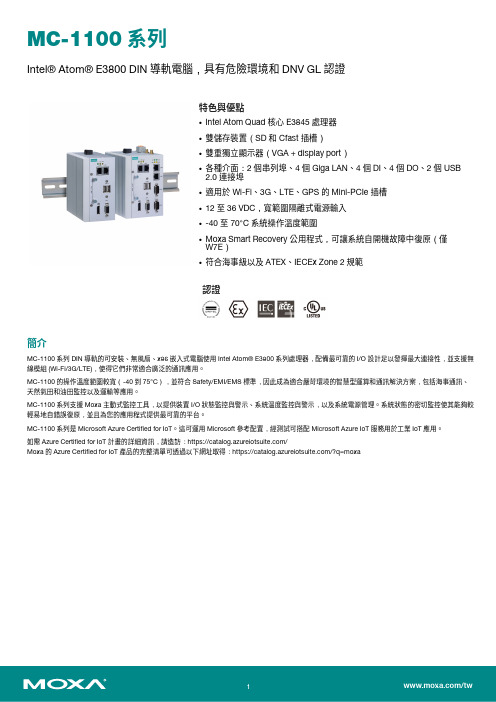
MC-1100系列Intel®Atom®E3800DIN導軌電腦,具有危險環境和DNV GL認證特色與優點•Intel Atom Quad核心E3845處理器•雙儲存裝置(SD和Cfast插槽)•雙重獨立顯示器(VGA+display port)•各種介面:2個串列埠、4個Giga LAN、4個DI、4個DO、2個USB2.0連接埠•適用於Wi-Fi、3G、LTE、GPS的Mini-PCIe插槽•12至36VDC,寬範圍隔離式電源輸入•-40至70°C系統操作溫度範圍•Moxa Smart Recovery公用程式,可讓系統自開機故障中復原(僅W7E)•符合海事級以及ATEX、IECEx Zone2規範認證簡介MC-1100系列DIN導軌的可安裝、無風扇、x86嵌入式電腦使用Intel Atom®E3800系列處理器,配備最可靠的I/O設計足以發揮最大連接性,並支援無線模組(Wi-Fi/3G/LTE),使得它們非常適合廣泛的通訊應用。
MC-1100的操作溫度範圍較寬(-40到75°C),並符合Safety/EMI/EMS標準,因此成為適合嚴苛環境的智慧型運算和通訊解決方案,包括海事通訊、天然氣田和油田監控以及運輸等應用。
MC-1100系列支援Moxa主動式監控工具,以提供裝置I/O狀態監控與警示、系統溫度監控與警示,以及系統電源管理。
系統狀態的密切監控使其能夠較輕易地自錯誤復原,並且為您的應用程式提供最可靠的平台。
MC-1100系列是Microsoft Azure Certified for IoT。
這可運用Microsoft參考配置,經測試可搭配Microsoft Azure IoT服務用於工業IoT應用。
如需Azure Certified for IoT計畫的詳細資訊,請造訪:https:///Moxa的Azure Certified for IoT產品的完整清單可透過以下網址取得:https:///?q=moxa外觀MC-1111MC-1121MC-1112MC-1122規格ComputerCPU MC-1100-E2-T Series:Intel Atom®Processor E3826(1M Cache,1.46GHz)MC-1100-E4-T Series:Intel Atom®Processor E3845(2M Cache,1.91GHz) Graphics Controller Intel®HD GraphicsSystem Memory Pre-installed4GB DDR3LSystem Memory Slot SODIMM DDR3/DDR3L slot x1Supported OS Linux Debian8(Linux kernel v4.1)Windows Embedded Standard7(WS7E)64-bitWindows10Embedded IOT Ent2016LTSBStorage Slot All models:CFast x1MC-1111/1121Series:SD x1Computer InterfaceEthernet Ports MC-1111/1112Series:Auto-sensing10/100/1000Mbps ports(RJ45connector)x2MC-1121/1122Series:Auto-sensing10/100/1000Mbps ports(RJ45connector)x4 Serial Ports MC-1121/1112Series:RS-232/422/485ports x2,software-selectable(DB9male)MC-1122Series:RS-232/422/485ports x4,software-selectable(DB9male)USB2.0USB2.0hosts x2,type-A connectorsDigital Input MC-1121/1122Series:DIs x4Digital Output MC-1121/1122:DOs x4Expansion Slots mPCIe slot x1TPM TPM v1.2(MC-1122-E4-TPM-T only)Video Output MC-1111/1121Series:VGA x1,DisplayPort x1All models:VGA x1,15-pin D-sub connector(female)Number of SIMs MC-1121/1122Series:1SIM Format MC-1121/1122Series:MiniLED IndicatorsSystem Power x1Storage x1LAN2per port(10/100/1000Mbps)Serial2per port(Tx,Rx)Serial InterfaceBaudrate50bps to115.2kbpsConnector DB9maleData Bits5,6,7,8Flow Control ADDC®(automatic data direction control)for RS-485RTS/CTS,XON/XOFFIsolation N/AParity None,Even,Odd,Space,MarkPower ParametersInput Voltage11.4to36VDCPower Connector Terminal block(for DC models)Power Consumption30W(max.)ReliabilityAutomatic Reboot Trigger Built-in WDTPhysical CharacteristicsHousing MetalDimensions MC-1111/1112Series:132x122x68mm(5.2x4.81x2.68in)MC-1121/1122Series:132x122x87mm(5.2x4.81x3.43in)Weight MC-1111/1112Series:1,022g(2.25lb)MC-1121/1122Series:1,340g(2.95lb) Installation DIN-rail mountingWall mounting(with optional kit) Environmental LimitsOperating Temperature-40to70°C(-40to158°F)Storage Temperature(package included)-45to75°C(-49to167°F)Ambient Relative Humidity5to95%(non-condensing)Standards and CertificationsEMC EN55032/24EMI CISPR32,FCC Part15B Class AEMS IEC61000-4-3RS:80MHz to1GHz:10V/mIEC61000-4-2ESD:Contact:6kV;Air:8kVIEC61000-4-8PFMFIEC61000-4-6CS:10VIEC61000-4-5Surge:Power:1kV;Signal:1kVIEC61000-4-4EFT:Power:2kV;Signal:1kV Hazardous Locations ATEX Zone2Class I Division2IECEx Zone2Maritime DNV-GLIEC60945Radio Frequency FCCSafety UL60950-1WarrantyWarranty Period3yearsDetails See /tw/warrantyPackage ContentsDevice1x MC-1100Series computerCable1x terminal block to power jack converter Installation Kit1x terminal block,2-pin1x DIN-rail kitDocumentation1x quick installation guide1x warranty card尺寸MC-1112MC-1122MC-1111MC-1121訂購資訊Model Name CPU RAM Storage SlotsOSPreinstalledLAN/Serial USB2.0Video OutputsInterfaceExpansionMC-1111-E2-T Intel Atom®E38264GB1x CFast1x SD–2/–21x VGA1x DP–MC-1111-E4-T Intel Atom®E38454GB1x CFast1x SD–2/–21x VGA1x DP–MC-1121-E2-T Intel Atom®E38264GB1x CFast1x SD–4/221x VGA1x DP1x mPCIeMC-1121-E4-T Intel Atom®E38454GB1x CFast1x SD–4/221x VGA1x DP1x mPCIeMC-1121-E4-T-W7E Intel Atom®E38454GB1x CFast(32GBpreinstalled)1x SDWS7E4/221x VGA1x DP1x mPCIeMC-1112-E2-T Intel Atom®E38264GB1x CFast–2/221x VGA–MC-1112-E4-T Intel Atom®E38454GB1x CFast–2/221x VGA–MC-1122-E2-T Intel Atom®E38264GB1x CFast–4/421x VGA1x mPCIeMC-1122-E4-T Intel Atom®E38454GB1x CFast–4/421x VGA1x mPCIeMC-1122-E4-TPM-T Intel Atom®E38454GB1x CFast–4/421x VGA1x mPCIe配件(選購)Cellular Wireless ModulesCELLULAR-LTE(L201)LTE cellular module,with2mounting screws,for LTE(FDD)bands B2,B4,B5,B13and B41in the NorthAmerican regionCELLULAR-LTE(L210)LTE cellular module,with2mounting screws,for LTE(FDD)bands B1,B3,B5,B7,B8and B20in Europeand APAC regionsWi-Fi Wireless ModulesWi-Fi-BGN(252NI)Wi-Fi module,2antennas with cable and connector,2black screws,2lock washers,2nuts,1thermalpadDIN-Rail Mounting KitsMC-1100DIN-Rail Kit DIN-rail mounting kit,4screwsWall-Mounting KitsMC-1100Wallmount Kit Wall-mounting kit,4screwsPower CordsPWC-C7AU-2B-183Power cord with Australian(AU)plug,2.5A/250V,1.83mPWC-C7CN-2B-183Power cord with two-prong China(CN)plug,1.83mPWC-C7EU-2B-183Power cord with Continental Europe(EU)plug,2.5A/250V,1.83mPWC-C7UK-2B-183Power cord with United Kingdom(UK)plug,2.5A/250V,1.83mPWC-C7US-2B-183Power cord with United States(US)plug,10A/125V,1.83mPower AdaptersPWR-24270-DT-S1Power adapter,input voltage90to264VAC,output voltage24V with2.5A DC load©Moxa Inc.版權所有.2020年1月31日更新。
SIEMENS Hipath 3800交换机

SIEMENS Hipath 3800交换机HiPath3800数字程控交换机是德国西门子公司最新一代推向市场的为中小企业提供通讯服务IP PBX功能的多媒体交换机,它可以提供最优的,多种多样的数字,模拟以及IP中继和用户线路接口。
Hipath3800程控交换机:最大384端口西门子HiPath 3800产品简介HiPath 3800 IP集成系统通过易用的高质量终端设备,为中型企业(可多达1000个用户)提供可靠的语音通信。
如果HiPath 3800作为独立系统使用,可支持达500个工作点。
64个HiPath 3800系统可进行透明联网。
HiPath 3800是新的一代具有改进性能的高端硬件平台。
可通过HiPath ComScendo为所有系统提供丰富的功能。
在HiPath3000/4000的组网当中,可做为HiPath4000可自愈的远端模块。
在无线移动语音应用中,可通过DECT及VoWLAN两种解决方案来实现,其中VoWLAN为真正意义上的IP层解决方案。
HiPath3800系统为用户在远距离工作,移动通信,多媒体应用,CTI方案等新的应用领域提供了解决方法。
HiPath3800采用统一的一个软件平台,可以适应不同规模公司的功能需求,其数字话机采用统一的optipoint 系列,其支持最佳经济路由选择,具有CornetN,Q-sig等多种组网信令,可为用户应用提供开发接口,具有综合无线通信方案,综合LAN解决方案。
HiPath3800交换机处理机采用IBM 专用通讯处理芯片,每端口话务量为0.54Erl,BHCA值为25000。
由于采用了现代通信,微电子和计算机技术,具有大规模集成度,因此该设备具有以下特点:体积小,处理能力强,接口品种多。
具有ISDN功能,可提供DSS1,CORNET,2B+D等多种信令。
操作方便,易于维护。
故障处理能力强,无风扇,功耗低HiPath 3800系统功能:(1)应答前语音提示。
思科Aironet系列2800 3800无线接入点部署指南说明书

思科 Aironet 系列 2800/3800 无线接入点部署指南首次发布日期: 2016年05月11日Americas HeadquartersCisco Systems, Inc.170 West Tasman DriveSan Jose, CA 95134-1706USATel: 408 526-4000800 553-NETS (6387)Fax: 408 527-0883本手册中有关产品的规格和信息如有更改,恕不另行通知。
本手册中的所有声明、信息和建议均准确可靠,但我们不为其提供任何明示或暗示的担保。
用户必须承担使用产品的全部责任。
随附产品的软件许可和有限担保在随产品一起提供的信息包中提供,且构成本文的一部分。
如果您无法找到软件许可或有限担保,请与思科代表联系以获取副本。
思科所采用的TCP报头压缩是加州大学伯克利分校(UCB)开发的一个程序的改版,是UCB的UNIX操作系统公共域版本的一部分。
保留所有权利。
版权所有©1981,加州大学董事会。
无论本手册中是否有任何其他保证,这些供应商的所有文档文件和软件均按“原样”提供,并可能包含缺陷。
思科和上面所提及的提供商拒绝所有明示或暗示担保,包括(但不限于)适销性、特定用途适用性和无侵权担保,或者因买卖或使用以及商业惯例所引发的担保。
在任何情况下,对于任何间接、特殊、连带发生或偶发的损坏,包括(但不限于)因使用或无法使用本手册而导致的任何利润损失或数据损失或损坏,思科及其供应商概不负责,即使思科及其供应商已获知此类损坏的可能性也不例外。
本文档中使用的任何互联网协议(IP)地址和电话号码并非实际地址和电话号码。
本文档中所含的任何示例、命令显示输出、网络拓扑图和其他图形仅供说明之用。
说明性内容中用到的任何实际IP地址或电话号码纯属巧合,并非有意使用。
思科和思科徽标是思科和/或其附属公司在美国和其他国家/地区的商标或注册商标。
要查看思科商标列表,请访问此网址:/go/trademarks。
Eaton xSpider 3.3 产品概述说明书

xSpider 3.3 –overviewxSpider -General features•All calculations are based on IEC standards•Suitable for TN/ IT/ TT network systems up to 1000V•Designed for networks supplied from single or multiple power supplies •Option of simulating various operating states of network by disconnecting individual power sources and loads•Operation state manager -complex simulation of various operating states,e.g graphically shows circuit breaker ON/OFF status•Selectivity-tripping characteristics and selectivity tables (tested values)•Back-up protection (tested values)•Arc RISK module-evaluation of risks caused by Arc-Flash•How to obtain xSpider ? /xspider•Simple registration of user -use of correct e-mail address•License number-delivered by server to e-mail address •How to start with xSpider 1.Demo drawings -ready for immediate use2.Self-learning videos -available on xSpider web pages3.Solved exaple-see …User manual“ Part IIIHow to start with xSpiderAvailable support materials significantlyhelp with quick use of xSpider functionalities.1. Demo drawings•Typical applications with short description of essential topics •Easy learning with readymade drawings•Quick access via Tool boxHow to opendemo exampleSelf-learning videos and presentations•How to open demo example •How to check voltage drop •How to change the paper size •How to draw wiring diagram•How to select a symbol and how to edit a symbol's properties •How to select a device from the database •How to activate graphic window for zooming•Automatic dimensioning of cables and protective devices •How to run a calculation•How to display a tripping characteristics from the database •How to display a tripping characteristics from the project •Selection modes explanation•xSpider -Generator Load Sharing functionality.•Export list of devices and import it to other softwareArcRISK (Arc Flash Risk Assessment)•ArcRISK Part 1 –Introduction•ArcRISK Part 2 -xSpider ArcRISK module possibilities/xspider2. Self-learning videosAvailable on xSpider web pages3. Solved examples in User manual•Available on xSpider web page (pdf format) •Quick access via icon …Help Topics“ (F1)•Step by step guide -how to create drawing …User manual“, Part III, Case studies (12 pages)Full modefull functionality of xSpiderCurve select modesimplified user interface, only functions for working with tripping characteristicsFull mode/ Curve select modeWorking with drawingsFlexible graphics areaTool BoxError ListRibbonMDI interfaceDocked panelsAll panels are sizableProperty GridTwo options:•Basic calculations•All calculationsHow to run a calculationCheck the network logic•Correct logic of wiring diagram is condition forany calculations•Typical troubles: detected wrong voltage of MVsource or not specifieed cable lengths of cablesCorrections ofwiring diagramOperation state manager•Simulation of various operation states of the network •Disconnecting power sources and loads•Each switching component has: On / Off•Each motor has two operating states: Start /RunThree-phase short circuit current •Maximum short-circuit current (I kmax)•Correct dimensioning of the circuit protection (breaking capacity I cu or I cs)and conductors(I cw)•Check of whole network or fault in selectednodeComponent with error(breaking capacity of circuit breaker is low) Correct interpretation of displayed results !I“k3pi p3pSingle-phase short circuit current•Minimum short-circuit current (I kmin) during earthfault;•Calculation of disconnection time (T tr);•Check of whole network or fault in one node;Component with error–tripping time ofselected circuit breaker FA2 is too longSelectivity•Comparison of circuit breakers in project •Selectivity assessment according to tested values(see Selectivity Guide)Comprehensive selectivity evaluation including tripping characteristics is available in the …Tripping characteristics“ module.Comprehensive check of the network•All available calculation results are displayed (voltage drop, circuit protection, short circuits);•Final calculatuin mode –suitable after all individual calculations were done well;Cable and protective devices dimensioningDesign mode (Automatic Dimensioning)•Parameterswill be automatically determined;•Suitable mode for simple projects•Final manual optimization can be donealways by use of …Control mode“ accordingly;Control mode (Manual Dimensioning)•Recommended way of work for bigger projects; •Parameters of all elements are set by the user Two options for parameter selectionHow to draw wiring diagramAutomatic dimensioning of cables and protective devicesCalculationsArcRISK moduleEvaluation of Arc Flash Hazard Analysis•Calculation of incident energy•Hazard analysis according to IEEE 1584™(see also EN 50110-1,-2)•Safety improvements with Eaton‘s solutions(Diagnose, ARMS™, ARCON)•Unique feature of xSpider!!•Access password on request•Application training on request•ArcRISK Part 1 –Introduction•ArcRISK Part 2 -xSpider ArcRISKmodule possibilitiesSelected icons for quick accessto mostly used functionalitiesRibbonsOne project may include multiplecollections of characteristics.Parameter settings of displayed deviceTripping characteristics featuresHow to display a tripping characteristics from the databaseHow to display a tripping characteristics from the projectTripping characteristicsfeaturesAdd tripping characteristicfrom DatabaseAdd Tripping characteristic from Project (Full mode only)User defined curvesRename tripping chars in collectionDelete tripping chars from collection Selectivity and back-upInformation about selectivity Current limiting characteristicsHelpCurrent limiting characteristicsCurrent limiting devices:-MCBs -RCBOs -Fuses-Motor starters (PKZ..)-Current limiter (CL-PKZ)-MCCBs up to 630 ALet-through energy characteristicsLet-through current(cut-off) characteristicsDynamic effect of short-circuit current Thermal effect of short-circuit currentEaton Industries (Austria) GmbHScheydgasse42, A-1215 Wien, Austria Phone: +43 0 28 53 7 02-0***************** /xspiderTechnical supportxSpider Installation Instructions。
David Clark 3800 Gateway用户手册说明书

USER MANUAL 3800 GatewayU9922-G38 U9922-G38(EU) (P/N: 40995G-01)(P/N: 40995G-02)C a u t i o n s a n d W a r n i n g sREAD AND SAVE THESE INSTRUCTIONS. Follow the instructions in this installationmanual. These instructions must be followed to avoid damage to this product andassociated equipment. Product operation and reliability depends on proper usage.DO NOT INSTALL ANY DAVID CLARK COMPANY PRODUCT THAT APPEARS DAMAGED. Upon unpacking your David Clark product, inspect the contents for shipping damage. If damage is apparent, immediately file a claim with the carrier and notify your David Clark product supplier.ELECTRICAL HAZARD - Disconnect electrical power when making any internal adjustments or repairs. All repairs should be performed by a representative or authorized agent of the David Clark Company.STATIC HAZARD - Static electricity can damage components. Therefore, be sure to ground yourself before opening or installing components.LI-POLYMER - This product is used with Li-Polymer batteries. Do not incinerate, disassemble, short circuit, or expose the battery to high temperatures. Battery must be disposed of properly in accordance with local regulations.The U9922-G38 (40995G-01) 3800 Gateway is a fixed-mounted wireless communication device that when used in conjunction with one or more U9910-BSW (40992G-01) or U9912-BSW (40992G-02) Wireless Belt Stations becomes part of a wireless intercom system. The U9922-G38 provides communication for up to four users as well as an interface to an existing David Clark Model 3800 wired intercom system. Additionally, the U9922-G38 can be used as a stand-alone wireless intercom gateway with two-way radio interface. Up to four belt stations can be connected to one gateway.InputFigure 1: Overview of GatewayIntercom InterfaceThe U9922-G38 can be configured in one of two ways: 3800 interface and stand-alone.3800 InterfaceThis configuration adds wireless capability to an existing 3800 wired intercom system and can replace a U3811 or U3815 radio interface module (see 3800 system documentationfor further details.) In this way, all wired and wireless users may communicate with each other as well as talk over and listen to a two-way radio. A C38-xx system cable andoptional C3821 radio interface cable are required for this configuration.Stand-aloneStand-alone configuration creates an ad-hoc wireless intercom and adds access to a two-way radio. This configuration does not connect to a 3800 wired intercom system. A C99-22PW (18748G-24) power cable and optional C3821 radio interface cable are required for this configuration.AntennaThe U9922-G38 has two external antenna connections and is supplied with one whip style antenna. In most applications a single whip antenna is sufficient. However the optional remote antenna kit (P/N: 40688G-93 for mag-mount, 40688G-96 for permanent install) is available should more range be desired. In this case, we recommend keeping one whip antenna connected directly to the U9922-G38 and routing the remote antenna somewhere else (such as on the roof of a vehicle).Choose an open, clear location for the remote antenna and route the coaxial cable away from any busy areas, preferably behind panels or in conduits.This device has been designed to operate with the antennas listed below, and having a maximum gain of 3 dB. Antennas not included in this list or having a gain greater than 3 dB are strictly prohibited for use with this device. The required antenna impedance is 50 ohms. Acceptable antennas for use with this product:•Whip Antenna (P/N: 40688G-92)•Remote Antenna Kit, Mag-Mount (P/N: 40688G-93)•Remote Antenna Kit, Permanent (P/N: 40688G-96)Before a belt station and a gateway can be connected, they must first be linked. As a securitymeasure, the close-link feature requires devices to be in proximity of about 1 to 3 ft (0.3 to 0.9m) in order to successfully link. This ensures that the units are not inadvertently linked with otherunits on the premises.Linking procedure:1.Ensure units are within 1 to 3 ft (0.3 to 0.9m) of each other.2.Simultaneously (within 1-2 sec) press and release the LINK button on the U9922-G38 andthe belt station to link with.3.Amber LED’s will flash quickly on both devices. A momentary red LED indicates asuccessful close-link.4.Upon successful link the U9922-G38 will attempt to establish a connection with the beltstation.5.Upon successfully establishing connection the LED on the gateway will flash a greenpattern corresponding to the number of belt stations connected.Tip:Once linked, the devices will not need to be linked again unless they are purged (seePurging).Each belt station is able to be linked to only one gateway at a time. A gateway can have up to six belt stations linked and be connected to four of those six at one time.S t a t u s I n d i c a t i o n sThe LINK button has a multi-color LED in the center which serves as a status indication for thegateway. Table 1 below lists these states.Table 1: LED Status IndicationsLED Color Blink Rate StatusRed Solid Initializing/power upRed Once Connection DroppedRed Once Connection EstablishedRed Any Low battery (approx. 1 hr remaining)Orange Slow Idle/DisconnectedOrange Fast Linking/Connection in ProgressOrange Solid PTT assertedGreen Slow Connected (pattern indicatesnumber of belt stations connected)CommunicationAll connected belt stations will be able to communicate with each other through the U9922-G38 while in range (and per the VOX settings on each VOX belt station.) Additionally, all belt station users will have communication over the intercom. If a two-way radio is installed to the U9922-G38, pressing the PTT button on a VOX belt station will allow the user to transmit over the system’s two-way radio. Pressing the PTT overrides the VOX setting on a VOX belt station. Multiple belt station users may PTT and thus speak over the two-way radio simultaneously. For more information consult the user manual for the belt station.Tip:Wireless users who are not pressing PTT while another wireless user is pressing PTT willnot be heard on the wired intercom while the PTT remains pressed.Intercom Level AdjustmentAudio levels can vary between intercoms, mainly due to the system level setting on the wired intercom. To compensate for this, the U9922-G38 has the ability to adjust its receive level from the intercom using the Volume knob (see Figure 1). Turning this knob will increase or decrease the audio level coming from the wired intercom into the gateway. Perform this adjustment to obtain optimum performance.Intercom Level Adjustment Procedure1.Connect at least one belt station to the U9922-G38 gateway and ensure sidetone ispresent (see belt station User Manual).2.Begin speaking and slowly turn the Volume knob on the U9922-G38 clockwise untilyou hear an echo of your own voice.3.Continue speaking and turn the Volume knob counter-clockwise until the echo stops.4.You may wish to verify communication with someone hard-wired to the intercom.Radio Level AdjustmentAudio levels to and from a two-way radio can also vary between radio models and manufacturers. To adjust the U9922-G38 for a particular radio, follow the procedures below.Radio Transmit Level Adjustment ProcedureNote: A radio service monitor is recommended for this adjustment.1.Connect at least one belt station to the U9922-G38 gateway and ensure sidetone ispresent (see belt station User Manual).2.Open the cover of the U9922-G38 and find the large silver knob.3.Press and hold the PTT and speak clearly and loudly into the microphone.4.Slowly turn the knob until the radio service monitor reads 4.0-4.5kHz deviation.a.Clockwise to increase level; counter-clockwise to decreaseRadio Receive Level Adjustment Procedure1.Connect at least one belt station to the U9922-G38 gateway and ensure side-tone ispresent (see belt station User Manual).2.Open the cover of the U9922-G38 and find the large silver knob.3.Tune the radio to a continuous transmission (such as NWS) or transmit a test signalfrom another radio.4.Adjust the volume control on the radio to a level slightly higher than typical.5.Slowly turn the knob until you hear a loud and clear signal on the wireless intercom.a.Clockwise to increase level; counter-clockwise to decreaseRangeThe range of a belt station and a gateway can be up to 300ft (100m). If you are in anenvironment with metal or concrete walls, this range could be reduced. When the belt stationtravels out of range of the gateway, a voice alert will indicate that the connection has been lost.To reconnect, simply move back into range and connection with the gateway will automatically be reestablished, also noted by a voice alert.P u r g i n gIn some circumstances it may be necessary to “purge” the U9922-G38 of some of its linked belt stations. Typically purging is not necessary unless there are multiple gateways in the samevicinity and you wish to remove a belt station from this gateway and link to a different gateway.A gateway can link up to six belt stations where a belt station can be linked to only one gatewayat a time.Smart PurgeA smart purge is the purge method employed for the U9922-G38, in which only unwanted linksare removed from the gateway. When this procedure is complete, only belt stations that areconnected to the gateway remain linked. All other belt station links will have been removed (see the belt station User Manual for the individual belt station purging procedure when remaininglink purging may be necessary.)Smart Purge procedure1.Ensure gateway is powered on and functioning.2.Disconnect all belt stations to be purged (power off the belt stations).3.Verify the number of green LED flashes on the gateway matches the number ofbelt stations to be kept linked.4.Press and hold LINK button on the gateway for 30 seconds until LED quicklyflashes red.5.Release LINK button.T r o u b l e s h o o t i n gTable 2: TroubleshootingProblem SolutionGateway will not turn on Review Installation procedureEnsure wiring is correct.Cannot link a belt station Review Linking procedureEnsure units are within 1 to 3ft (0.3 to 0.9m) ofeach otherTry a Smart PurgeCannot speak over two-way radio PTT not pressedNo radio connected to U9922-G38R e p l a c e m e n t P a r t s•System cable (C38-xx; number after dash indicates length in feet)•Power Cable (C99-22PW, P/N:18748G-24)•Radio Interface Cable (C3821, P/N: 18747G-06)•Whip Antenna (P/N: 40688G-92)•Remote Antenna Kit, Mag-Mount (P/N: 40688G-93)•Remote Antenna Kit, Permanent (P/N: 40688G-96)C a r e a n d M a i n t e n a n c eThe U9922-G38 is not user serviceable. Do not attempt to open the enclosure (unless adjusting the radio level per the procedures noted in this manual.) If this product requires service, please contact the David Clark Customer Service department:•Phone:800.298.6235•E-Mail:*************************•By Mail:Customer ServiceDavid Clark Company360 Franklin StreetWorcester, MA 01604If necessary, the U9922-G38 may be wiped down with a mild soap and water mixture. Although it is a sealed device designed to withstand submersion in water to 1 meter, do not unnecessarily submerse this product in water.Avoid storage of this product in direct sunlight or high temperature environments.S p e c i f i c a t i o n sFrequency Range 1920 MHz - 1930 MHz (U.S. and Canada)1880 MHz - 1900 MHz (EU)Average RF Power Output 4 mW (100mW peak) (U.S. and Canada)10 mW (250 mW peak) (EU)Range 300 ft (100m) line-of-sight (nominal)Operating Temperature -14°F to 113°F (-10°C to +45°C)Storage Temperature -4°F to 140°F (-20°C to +60°C)Power Requirements 8 to 32 VDCF C C P a r t15S t a t e m e n tRADIO AND TELEVISION INTERFERENCEThis equipment has been tested and found to comply with the limits for a Class B digital device, pursuant to Part 15 of the FCC rules. These limits are designed to provide reasonable protection against harmful interference in a residential installation. This equipment generates, uses and can radiate radio frequency energy and, if not installed and used in accordance with the instructions, may cause harmful interference to radio communications. However, there is no guarantee that interference will not occur in a particular installation. If this equipment does cause harmfulinterference to radio or television reception, which can be determined by turning the equipment off and on, the user is encouraged to try to correct the interference by one or more of thefollowing measures:- Reorient or relocate the receiving antenna.- Increase the separation between the equipment and the receiver.- Connect the equipment into an outlet on a circuit different from that to which the receiver isconnected.- Consult the dealer or an experienced radio/TV technician for help.You may also find helpful the following booklet, prepared by the FCC: "How to Identify and Resolve Radio-TV Interference Problems." This booklet is available from the U.S.Government Printing Office, Washington D.C. 20402.* In order to maintain compliance with FCC regulations shielded cables must be used withthis equipment. Operation with non-approved equipment or unshielded cables is likely to resultin interference to radio & television reception.I n d u s t r y C a n a d a S t a t e m e n tThis device complies with Industry Canada licence-exempt RSS standard(s). Operation is subjectto the following two conditions: (1) this device may not cause interference, and (2) this devicemust accept any interference, including interference that may cause undesired operation of thedevice.U n a u t h o r i z e d C h a n g e sChanges or modifications not expressly approved by David Clark Company, Inc. could void theusers’ authority to operate the equipment.F C C R a d i a t i o n E x p o s u r e S t a t e m e n tThis equipment complies with FCC radiation exposure limits set forth for an uncontrolledenvironment. This equipment should be installed and operated with a minimum distance of 20centimeters (8 inches) between the radiator (antenna) and your body. This transmitter must notbe co-located or operating in conjunction with any other antenna or transmitter.U s a g e R e s t r i c t i o n sUS ModelsDue to the UPCS frequencies used, this product is licensed for operation only in the United Statesof America and Canada.EU ModelsDue to the DECT frequencies used, this product is licensed for operation only in the EuropeanUnion countries.19541P-43 (02-11)9 of 9。
Hirschmann交换机配置手册

2
百通网赫思曼络系统国际贸易 (上海) 有限公司
1.准备
1.1 硬件准备 在对网络系统进行配置前,必须先对系统的硬件配置进行相应的检查。 必须保证所有的交换机均正常上电,并成功启动,所有交换机均可 以正常通信 在进行环网配置前,必须保证每个环网为线型链路 具有一台配置电脑以及至少一台的测试电脑
<操作界面>
<桌面图标>
PuTTY(在 Manual CD 中的 Freeware 文件夹) 支持 telnet、 rlogin 和 ssh 的客户端软件, 用于 CLI 命令配置, 操作简易。
5
百通网赫思曼络系统国际贸易 (上海) 有限公司
赫思曼交换机配置手册
百通网赫思曼络系统国际贸易 (上海) 有限公司
目录Biblioteka 1.准备 ..................................................................................................................................... 3 1.1 硬件准备 ............................................................................................................................ 3 1.2 软件准备 ............................................................................................................................ 3 2.配置 ..................................................................................................................................... 7 2.1 初始化设置 ....................................................................................................................... 7 2.2 Basic Settings基本配置 ............................................................................................. 10 2.3 Time对时功能 ................................................................................................................. 14 2.4 Switching交换功能 ....................................................................................................... 17 2.5 Redundancy 冗余设置 ................................................................................................... 21 2.6 Diagnostics 诊断 ......................................................................................................... 24 2.7 Help 帮助 ....................................................................................................................... 29 3 常见网络故障原因及应对方法 ....................................................................................... 30
赫斯曼交换机配置配置HIPER-Ring(更新)
23
Thank You End of Presentation
24
在MACH3000和MACH4000系列中,作为环端口的Port1必须在第一个基板上,即在交换 机最底层的那个基板上.
4
HIPER-Ring
通过硬件RM开关设置HIPER-Ring 通过硬件RM开关设置HIPERRM开关设置HIPER
5
HIPER-Ring
第一步: 第一步:
按照网络拓扑结构连接设备,其中RS20为冗余管理器,将硬件RM开关置于1.
保存交换机的当前配置到本机中
21
HIPER-Ring
第六步: 第六步:
以上步骤已经将Hiper-Ring配置完毕, 此时MS20(冗余管理器)的RM指示灯为 黄色,说明环网断开,冗余链路激活.
将MACH-3001和MS20(192.168.1.22) 连接起来,此时环网中无断点, MS20 (冗余管理器)的RM指示灯为绿色,说 明冗余链路在工作中,待被激活. 如图:
关闭RSTP
18
HIPER-Ring
在MACH3001中,点击左侧的Switching→Rapid Spanning Tree→Global, 选择OFF并单击Set,如图:
关闭RSTP
19
HIPER-ห้องสมุดไป่ตู้ing
第四步: 第四步:
由于已经将MS20(192.168.1.22)硬件Ring Ports开关置于0,所以环端口为模块1的Port1 和Port2,另外其硬件RM开关为0,所以需要通过软件开启RM.点击左侧的Redundancy→ HIPER-Ring,选择Redundancy Manager中的On.如图:
冗余链路为Active 冗余链路为Active 说明环网中某条链路失效 冗余链路开始工作
hipath 3000安装和概述
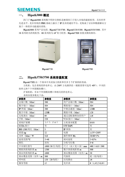
一、Hipath3000概述西门子Hipath3000系统数字程控交换机是德国西门子投入市场的最新机型,具有世界先进水平,是在传统的PBX基础上融合了IP技术的通信平台,是集成了话音和数据解决方案于一体的多功能通讯系统。
Hipath3000系列产品包括:Hipath3750/3700、Hipath3550/3500、Hipath3350/3300,其中50系列的为传统机型,00系列的为19”英寸机型,Hipath37XX容量及模块相同。
Hipath3750 Hipath3700二、Hipath3750/3700系统容量配置Hipath37XX由一个基本中央设备主机柜和至多2个扩展机柜组成。
主机柜:包含系统的供电单元,由230V主电源供给(根据需要可选用-48V),中央控制单元和7个外围模块槽口。
扩展机柜:有8个外围模块槽口和相关的供电单元。
系统容量参数见下表:三、 Hipath3750/3700系统接口四、 Hipath3750系统主要配件说明主控板(CBCPR ):包含了中央控制单元。
多媒体卡(MMC ):CBCPR 的插入式内存卡,容量为16MB ,带CDB 备份。
模拟分机/G3传真机 a/b a/b (环流直流信令)反极性语音信箱 Phonemail广播系统 Speaker ISDN S 0接口 2B+D 呼叫等待音乐 MOHISDN S 2M 接口 30B+DOptipoint500 2B+D/U POOptipoint 适配器Attendant P a/b (E&M 信令)2/4线制S 0数据终端 2B+D ISDN S 2M 接口 30B+DG4传真机ISDN 电话机带标准ISDN 卡的PCDECT 基站V.24 V .24ADSS L A TML8 STMD公 用 网TMS2M SL M O S T MD S L CCPU(MMC)IMODC HXGM TMS2M TIEL 专 用 网以太 网远程维护维护终端计算机系统远程维护卡(IMODC):用于从远端通过维护软件修改、设置系统参数。
- 1、下载文档前请自行甄别文档内容的完整性,平台不提供额外的编辑、内容补充、找答案等附加服务。
- 2、"仅部分预览"的文档,不可在线预览部分如存在完整性等问题,可反馈申请退款(可完整预览的文档不适用该条件!)。
- 3、如文档侵犯您的权益,请联系客服反馈,我们会尽快为您处理(人工客服工作时间:9:00-18:30)。
HiPath3800配置的注意事项
在电源方面有以下限制
1.主柜,在板卡少于5块,没有STMI2,SLMA,SLCN时,使用1个电源单元
2.主柜,在板卡少于5块,有STMI2,SLMA,SLCN使用,使用2个电源单元
3.主柜,板卡大于等于5块,没有STMI2,SLMA,SLCN时,使用2个电源单元
4.主柜,板卡大于等于5块,有STMI2,SLMA,SLCN时,使用2个电源单元
5.扩柜,在板卡少于5块,没有STMI2,SLMA,SLCN时,使用1个电源单元
6.扩柜,在板卡少于5块,有STMI2,SLMA,SLCN时,使用2个电源单元
7.扩柜,板卡大于等于5块,没有STMI2,SLMA,SLCN时,使用2个电源单元
8.扩柜,板卡大于等于5块,有STMI2,SLMA,SLCN时,使用3个电源单元
9.扩柜,板卡大于等于10块,没有STMI2,SLMA,SLCN时,使用3个电源单元
10.扩柜,板卡大于等于10块,有STMI2,SLMA,SLCN时,使用3个电源单元
在板卡方面有PCM段的限制
对于基本机柜,提供2种PCM通道,每种通道组为2个,每组4个PCM段,每个PCM 段的可用的通道大约为32个时隙
只使用基本机柜时,DIUN2,IVMNL,IVMN8和STMI2板卡使用A通道。
●PCM段分配,在板卡槽位1-5=128时隙(4组,每组32个时隙)
●PCM段分配,在板卡槽位7-10=128时隙(4组,每组32个时隙)
即为:
●1-5槽位有128个时隙的A总线,有128个时隙的F总线
●7-10槽位有128个时隙的A总线,有128个时隙的F总线
一个机柜的时候,DIUN2,IVMNL,IVMN8,STMI2如果用到F总线时,会在1-5和7-10槽位为这些板卡添加128时隙供其使用。
如果板卡要使用超过2x128个F总线的时候系统会自动使用空闲的A总线的时隙。
两个机柜的系统(基本柜+扩展柜)
所有的板卡都使用A总线的PCM段
●1-6槽位的板卡使用一个PCM段为128个时隙(四路通道,一路为32个时隙)●8-14槽位的板卡使用一个PCM段为128个时隙(四路通道,一路为32个时隙)扩展柜的F总线没有使用。
在扩展柜的A总线不够用的时候自动占用基本柜的空闲的F 总线。
基本柜的A总线不够用的时候也自动占用空闲的F总线,
板卡占用的通道数
HiPath3000升级到V5.0的注意事项
HiPath37系列、HiPath35系列、HiPath33系列升级方面
1.各种版本(V1.2/V
2.0/V
3.0/V
4.0)升级到V
5.0,哪些可以升级,哪些
不能升级
均可以升级, 参见启博价格表中的升级包
2.升级到V5.0后,哪些板卡可以使用、哪些不能使用
机框内的主板\MMC\HG1500 V2.0 均需要更换。
对于2M板卡参照下问
3.由老版本升级到V5.0,S2M板和HG1500板,什么情况下要重新购买
License
HG1500由V2.0更换为V3.0后license 不需要另外购买,由西门子提供转化后LICENSE CODE. (License激活码)
关于S2M,
只有新的S2M模块
HiPath3x00 系列使用的S2M卡TS2RN
S30810-K2913-Z300
HiPath3x50 系列使用的S2M卡TS2N
S30810-H2913-X300
HiPath3800 使用的S2M卡DIUN2
S30810-Q2196-X
必须要开通S2M板的License(L30250-U622-B328)才可以使用,包括V5.0的系统和从V4.0升级到V5.0的系统。
原有的HiPath37xx系列的TMS2的数字中继板卡
S30810-Q2915-X
不需要L30250-U622-B328
注意:老的HiPath37xx系列的板卡
TMS2M S30810-Q2537-X
SLA16 S30810-Q2702-x
TMOM S30810-Q2535-x
在V5.0版本上不可以使用
4.原有的基站,在升级到
5.0后还可不可以使用,或者是经过什么程序才
可以使用,是否需要费用
可以继续使用,关于LICENSE 需要进一步确认(注:西门子答复)
5.原有的数字话机和适配器及直选台等配件是否可以使用
可以使用
HG1500方面
●自带的2通道如何激活
现场如果不能开通,请申请LICENSE,自带2B为免费的
WLAN方面(无线LAN网)
●什么时候可以实施,相关的技术资料及介绍
WLAN 是处于西门子产品经理受控阶段,有项目需要可以直接报给西门子邓文欣先生。