沙特阿美工程规程SAEP-110 Saudi Aramco Standard Drawings
阿美公司规范
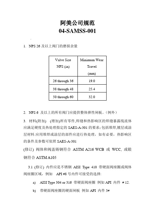
阿美公司规范04-SAMSS-001.1.NPS 26及以上阀门的磨损余量2.NPS 6 及以上的所有阀门应提供整体弹性闸板。
(例外)3.材料(附加) (增加)所有零件,焊缝和热影响区的焊缝暴露线流体应满足硬度及热处理指定的SAES-A-301的要求;包括堆焊,镀层或涂层材料.应用堆焊或涂层的部件应进行热处理,如有必要,热影响区的条件及参数可依照SAES-A-301(修订) 阀体和阀盖铸钢符合ASTM A216 WCB 或WCC, 或锻钢符合ASTM A1053.1(修订) 内件应是不锈钢AISI Type 410 带硬面阀座圈或阀体阀座圈区域,例如API #8号内件可接受的选择:a)AISI Type 304 or 316 带硬面阀座圈例如API 内件# 12.b)带硬面阀座圈的硬面闸板例如API 内件5#4.低温介质(-45 to -18°C)4.1内件须为不锈钢AISI Type 304 或316. 阀座圈须为硬面加司太立#6或等同(API STD 600 内件# 12).5.填料(附加)5.1 碳氢化合物介质下阀杆填料应是由含碳99% 的端环(John Crane - 1625G 或等同)和石墨中间环(John Crane - 237 或等同) 两种编织石墨丝组成的混合填料6.-101 to -45°C超低温介质(附加–仅指定时适用)6.1-101 to -45°C超低温介质阀门的附加a) 阀门应完全由不锈钢AISI Type 304 或316制造. 阀座圈须为硬面加司太立#6或等同(API STD 600 内件# 12).b) 体盖螺栓连接, 压盖螺栓, 压盖螺栓定位器及阀盖到支架的螺栓连接应为奥氏体不锈钢ASTM A320系列. 相应的螺母应为ASTM A194 8级系列c) (附加) 碳氢化合物介质下阀杆填料应是由含碳99% 的端环(John Crane - 1625G 或等同)和石墨中间环(John Crane - 237 或等同) 两种编织石墨丝组成的混合填料d) 泄压关闭零件的回流边上需钻3-5 mm的小孔. 阀体上应清晰标记流向.e) 泄压关闭零件的回流边上需钻3-5 mm的小孔. 阀体上应清晰标记流向.04-SAMSS-0351.水线要求1.1钢制光滑式密封面法兰垫片的接触面全,需要机械光面精整, 完成射程3.2到6.4微米2.排水管,通风口和阀体其他配件(钢阀)2.1 所有排泄阀门及相关管道零件抗耐腐蚀至少相当于内件材料,最低标准为AISI 316L SS3.材质3.1 当对焊连接阀门用碳钢和最低屈服强度289 MPa (42,000psi)或更高,最高碳含量不得超过0.26%.对于编织阀门,这种限制仅适用于端口。
沙特阿美工程规程SAEP-341 Equipment Life Cycle Cost Procedure

Previous Issue: 26 July 2009 Next Planned Update: 20 October 2017Page 1 of 14 Primary contact: Odan, Nabeel Mohammad on 966-3-8809506Engineering ProcedureSAEP-34120 October 2012 Equipment Life Cycle Cost Procedure Document Responsibility: Pumps, Seals & Mixers Standards CommitteeSaudi Aramco DeskTop StandardsTable of Contents1 Scope (2)2 Applicable Equipment Typesand Required LCC Data (2)3 Applicable Documents (3)4 Instructions (4)Appendix A – Calculation Methodsfor Life Cycle Cost Analysis (9)Next Planned Update: 20 October 2017 Equipment Life Cycle Cost Procedure1 ScopeThis procedure provides instructions for economically evaluating major equipmentpurchases with regards to their estimated total ownership cost (Life Cycle Cost) toSaudi Aramco over a twenty (20) years period. These costs include procurement andoperation cost (energy cost and quantifiable periodic maintenance) of the equipment.This procedure details the requirements for determining Life Cycle Costs (LCC) forpurchases of major equipment identified in Section 2. The applicable LCC analysisSpreadsheets provide a practical vehicle for performing the required calculations.2 Applicable Equipment Types and Required LCC DataNext Planned Update: 20 October 2017 Equipment Life Cycle Cost Procedure 3 Applicable Documents3.1 Saudi Aramco Materials System Specifications14-SAMSS-531Power Transformers17-SAMSS-502Induction Motors17-SAMSS-510Brushless Synchronous Generator17-SAMSS-520Synchronous Motors31-SAMSS-001Centrifugal Compressors31-SAMSS-004Centrifugal Pumps31-SAMSS-006Integrally Geared Centrifugal Compressor32-SAMSS-021Manufacture of Industrial Boilers32-SAMSS-029Manufacture of Fired Heaters3.2 Saudi Aramco Engineering StandardsSAES-F-001Design Criteria of Fired HeatersSAES-G-005Centrifugal PumpsSAES-K-402Centrifugal CompressorsSAES-P-113Large Electrical MotorsSAES-P-121Power Transformers3.3 Saudi Aramco Standards Data Sheet2741-ENG & Centrifugal Pump Data Sheet for2741-M-ENG Horizontal Pumps and Vertical In-line Pumps2748-ENG & Centrifugal Pump Data Sheet for2748-M-ENG Vertical Line Shaft Pumps8150-ENG & Packaged Integrally Geared Centrifugal8150-M-ENG Air Compressor Data SheetForm 9550-ENG Watertube Boiler Data Sheets (herein referred to asData Sheet)175-323700Manufacture of Fired Heaters3.4 Life Cycle Cost SpreadsheetsThe following spreadsheets are to be used in the analysis and are available in theForms section of the Engineering Standards website:LCC-001Centrifugal Pumps (31-SAMSS-004) *Next Planned Update: 20 October 2017 Equipment Life Cycle Cost ProcedureLCC-002Centrifugal Pump-Motor Trains (31-SAMSS-004)LCC-005Centrifugal Compressors (31-SAMSS-001) *LCC-006Centrifugal Compressor-Motor Trains(31-SAMSS-001)LCC-010Integrally Geared Centrifugal Compressor-MotorTrains (31-SAMSS-006)LCC-019Induction Motors (17-SAMSS-502) *LCC-020Synchronous Motors (17-SAMSS-520) *LCC-023Power Transformers (14-SAMSS-531)LCC-024Boilers (32-SAMSS-029)LCC-024A Dual Fuel Boilers (32-SAMSS-021)LCC-025Fired Heaters (32-SAMSS-029)LCC-025A Dual Fuel Fired Heaters (32-SAMSS-029)* These spreadsheets are to be used when buying stand-alone pumps,compressors, or motors. For equipment trains (i.e., motor driven pump train,etc.), the train work sheets are to be used.4 Instructions4.1 SAPMT Submittal of Project Equipment ListsSaudi Aramco Project Management Team (SAPMT) shall prepare and includethe following items in the project proposal documents:4.1.1 A list of the Project's equipment items that are covered by the aboveSAMSS.4.1.2 A list of equipment items subject to LCC analysis. This list is to beincluded in schedule G of the contract. A copy is to be sent toEstimating Services Division (ESD/PMOD) so that they includeadditional allowances in the ER estimate to cover the differential inequipment cost due to LCC analysis.4.1.3 A list of equipment items with long lead-time delivery that may requireexpedited SAPMT bid development.4.1.4 A list of the latest applicable energy costs obtained from FPD.Next Planned Update: 20 October 2017 Equipment Life Cycle Cost Procedure4.2 Equipment Requiring SAPMT Bid DevelopmentFor equipment requiring SAPMT bid development prior to contract award (longlead equipment), the following steps shall be implemented:4.2.1 Upon receipt of the equipment bids, SAPMT's technical evaluation shallensure that the bids contain the required data needed to perform LCCanalysis.4.2.2 SAPMT shall submit the bids technical data to CSD for review and shallhighlight the technical LCC data (i.e., power, efficiency, operatingfactor) that will be used in the LCC analysis.4.2.3 CSD shall review the technical bid data along with the LCC data elementsand provide comments, if any, to SAPMT within 10 working days.4.2.4 SAPMT shall perform the LCC analysis by utilizing the applicable LCCSpreadsheet (s) to determine the Life Cycle Cost for each acceptablevendor. Other quantifiable cost factors that may significantly impact theeconomic analysis (such as delivery dates) may be included in the LCCanalysis. Inclusions of supplementary cost factors require the priorapproval of the project manager and CSD's concurrence.4.2.5 SAPMT shall calculate the savings (S LCC) in life cycle cost according tothe following equation:S LCC = LCC LIB– LCC LV (1)where:LCC LV is the equipment life cycle cost of the vendor with the lowestoverall LCCLCC LIB is the life cycle cost of the vendor with the lowest initial bid4.2.6 Purchase Order (P/O) shall be placed with the vendor having the lowestLCC (LCC LV) if S LCC is equal to $25000 or 5% of the LIB whichever ishigher.4.2.7 After P/O placement, SAPMT shall submit a copy of the final LCCSpreadsheet(s) to Estimating Services Division (ESD/PMOD) forarchiving and to CSD for information.4.2.8 If Project Management awards to a vendor, a purchase order with apotential performance liability based on the provisions of the applicableSAMSS (penalty clause), and the purchase order is to be transferred(“novated”) to the successful LSTK contractor on the project, ProjectNext Planned Update: 20 October 2017 Equipment Life Cycle Cost Procedure Management and/or Purchasing must include provisions in the NovationAgreement that specifically describe the liability being assumed by thecontractor.4.2.9 The equipment shall be tested at the vendor facility for guaranteedefficiency if required by the applicable Saudi Aramco Materials SystemSpecification (SAMSS) and/or the Project Contract. If the equipmentdoes not meet the specified efficiency, and cannot be corrected withinthe test tolerance as specified in the SAMSS, a penalty shall be imposedon the supplier as defined in the SAMSS and the Purchase order.4.3 Equipment Not Requiring SAPMT Bid DevelopmentFor Contractor procured equipment (all non-long-lead time equipment) thefollowing steps shall be implemented:4.3.1 After evaluating the vendor submittals, the Contractor shall provide thebid technical data, required commercial data per schedule G, and theequipment site delivery date for each vendor to SAPMT for review.4.3.2 SAPMT shall review the information to determine if it contains all of therequired data needed to complete the LCC analysis and shall require theContractor to provide any missing or unacceptable data.4.3.3 SAPMT shall provide a copy of the bid technical data including the LCCdata elements (operating factor, efficiency at normal load point, etc.), toCSD for review.4.3.4 CSD shall review the technical bid data along with the LCC dataelements and provide comments to SAPMT within 10 working days.4.3.5 SAPMT shall perform the LCC analysis by utilizing the applicable LCCSpreadsheet(s) to determine the Life Cycle Cost for each acceptablevendor. Other quantifiable cost factors that may significantly impact theeconomic analysis (such as savings due to early delivery) may beconsidered for inclusion in the LCC analysis. Inclusions ofsupplementary cost factors require the prior approval of the projectmanager and CSD's concurrence.4.3.6 SAPMT shall calculate the savings (S LCC) in life cycle cost according tothe following equation:S LCC = LCC LIB– LCC LV(2)Next Planned Update: 20 October 2017 Equipment Life Cycle Cost Procedure where:LCC LV is the equipment life cycle cost of the vendor with the lowestoverall LCCLCC LIB is the life cycle cost of the vendor with the lowest initial bid4.3.7 SAPMT shall direct the contractor to place the Purchase Order (P/O)with the vendor having the lowest LCC (LCC LV) if S LCC is equal to105% or higher of the compensation to the LSTK Contractor (refer toparagraph 4.3.8).4.3.8 If the COMPANY directs the CONTRACTOR to purchase theequipment from any manufacturer technically qualified by theCONTRACTOR other than the CONTRACTOR's proposed source ofsupply, the COMPANY shall compensate the CONTRACTOR for anydifference between the total delivered equipment cost ofCONTRACTOR's proposed source of supply and that of the COMPANYdirected manufacturer.4.3.9 After P/O placement, SAPMT shall provide a copy of the final LCCSpreadsheet(s) to the Estimating Services Division (ESD/PMOD) forarchiving and to CSD for information.4.3.10 The equipment shall be tested at the vendor facility for guaranteedefficiency if required by the applicable Saudi Aramco Materials SystemSpecification (SAMSS) and/or the Project Contract. If the equipmentdoes not meet the specified efficiency, and cannot be corrected withinthe test tolerance as specified in the SAMSS, a penalty shall be imposedon the contractor as defined in the SAMSS and the Project Contract.4.4 All Direct Charge Purchases Requiring LCC AnalysisFor Direct Charge (D/C) procurement of equipment, the following steps shall beimplemented:4.4.1 The Proponent Requisition Originator shall develop the PurchaseRequisition (PR) or the Request for Quotation (RFQ) for the subjectequipment and forward it to Purchasing for bid development. If therequested equipment requires LCC analysis as specified in the applicableSAMSS, the Requisition shall clearly indicate the required LCC datawhich the bidders need to provide.4.4.2 Upon receipt of the PR or the RFQ, the Purchasing Buyer shall reviewthe indicated line items and specifications to determine if any of theNext Planned Update: 20 October 2017 Equipment Life Cycle Cost Procedure items require LCC analysis.4.4.3 Upon receipt of bids, the Buyer shall request the Proponent RequisitionOriginator to perform the technical evaluation.4.4.4 The Buyer shall obtain the latest applicable energy costs from FPD foruse in the LCC analysis.4.4.5 The Buyer shall perform the LCC analysis by utilizing the applicableLCC Spreadsheet(s) to determine the Life Cycle Cost for all technicallyand commercially acceptable vendors.4.4.6 The buyer shall calculate the savings (S LCC) in life cycle cost according tothe following equation:S LCC = LCC LIB– LCC LV(3)where:LCC LV is the equipment life cycle cost of the vendor with the lowestoverall LCC costLCC LIB is the life cycle cost of the vendor with the lowest initial bid4.4.7 Purchase Order (P/O) placement shall be with the vendor having thelowest LCC (LCC LV) if S LCC is equal to $25000 or 5% of the LIBwhichever is higher.4.4.8 If the equipment cost for the selected equipment is higher than the PR'sauthorized limit, the Requisition Originator (Proponent) shall initiate aChange Requisition to authorize these additional funds.4.4.9 After P/O placement, Buyer shall submit a copy of the final LCCSpreadsheet to Estimating Services Division (ESD/PMOD) for archivingand a copy to CSD for information.The equipment shall be tested at the vendor facility for guaranteedefficiency if required by the applicable Saudi Aramco MaterialsSpecification (SAMSS) and/or the Project Contract. If the equipmentdoes not meet the guaranteed efficiency, and cannot be corrected withinthe test tolerances allowed, a penalty shall be imposed upon the supplierin accordance with the terms and conditions specified in the applicablePurchase Order.Revision Summary13 October 2012 Major revision.Next Planned Update: 20 October 2017 Equipment Life Cycle Cost ProcedureAppendix A – Calculation Methods for Life Cycle Cost AnalysisThis section is included in this SAEP for clarification purpose only. The logic is already included in the Life Cycle Cost Spreadsheets.A.1 Centrifugal Pumps and Centrifugal CompressorsUnless otherwise approved by the Coordinator, Rotating Equipment Division,Consulting Services Department, the Life Cycle Cost (LCC) of the centrifugalpumps and centrifugal compressors is determined from the following formula:LCC = IC + OC (4)where:IC = Initial Cost, $ (Purchase order cost of all equipment being bought)OC = Present value of Operating power Cost, $, for operating period of20 years= P * EF * No. of units being boughtP = Equipment Power in kW, at normal flow rate for actual fluid.EF = Evaluation Factor ($/kW) will be shown on the data sheet and/or inthe quotation request= 11.56 * EC * AHEC = Energy Cost in $/kWhAH = Annual operating Hours= OF * 8760OF = Operating Factor= Number of Operating Units divided by the number of units beingbought.Next Planned Update: 20 October 2017 Equipment Life Cycle Cost ProcedureA.2 Electrical Motor Driven Centrifugal Pump, Electrical Motor Driven CentrifugalCompressor and Electrical Motor Driven Integrally Geared Compressor TrainsUnless otherwise approved by the Coordinator, Rotating Equipment Division,Consulting Services Department, the Life Cycle Cost (LCC) of the electricalmotor driven trains is determined from the following formula:LCC = IC + OC (5)where:IC = Initial Cost, $ (Purchase order cost of all trains being bought)OC = Present value of Operating power Cost, $, for operating period of20 years= P/(Em*EG) * EF * No. of trains being boughtP = Driven equipment Power in kW, at normal flow rate for actualfluid.Em = Motor Efficiency at normal operating load (decimal)EG = Gear Efficiency at normal operating load (decimal). If there is nogear, EG = 1EF = Evaluation Factor ($/kW) will be shown on the data sheet and/or inthe quotation request= 11.56 * EC * AHEC = Energy Cost in $/kWhAH = Annual operating Hours= OF * 8760OF = Operating Factor= Number of operating trains divided by the number of trains beingbought.Next Planned Update: 20 October 2017 Equipment Life Cycle Cost ProcedureA.3 Electrical MotorsUnless otherwise approved by the Coordinator, Electrical Systems MechanicalDivision, Consulting Services Department, the Life Cycle Cost (LCC) of theelectrical motors is determined from the following formula:LCC = IC + OC (6)where:IC = Initial Cost, $ (Purchase order cost of all motors being bought)OC = Present value of Operating power Cost, $, for operating period of20 years= RP * EF * No. of motors being boughtRP = Required Power in kW= P/EmP = Motor load in kW, at normal operating conditions.Em = Motor vendor's Guaranteed Efficiency at normal operating load(decimal)EF = Evaluation Factor ($/kW) will be shown on the data sheet and/or inthe quotation request= 11.56 * EC * AHEC = Energy Cost in $/kWhAH = Annual operating Hours= OF * 8760OF = Operating Factor= Number of operating motors divided by the number of motorsbeing bought.Next Planned Update: 20 October 2017 Equipment Life Cycle Cost ProcedureA.4 Life Cycle Cost Evaluation for Boilers and Fired HeatersUnless otherwise approved by the Coordinator, Mechanical & Civil EngineeringDivision, Consulting Services Department, the Life Cycle Cost (LCC) of theboilers and fired heaters is determined from the following formula:Single Fuel Services:LCC = IC + OC (7)where:IC = Initial Cost, $ (Purchase order cost of all units being bought)OC = Present value of Operating power Cost, $, for operating period of20 years= CF * EF * No. of units being boughtCF = Consumed Fuel (Heat Release) in MMBTU/hr= L/EFFL = Unit load (Duty) at normal condition (MMBTU/hr) provided in thedata sheet by the buyer.EFF = Unit Efficiency (decimal) at normal condition provided by vendor.EF = Evaluation Factor ($-hr / MMBTU) will be shown on the data sheetand/or in the quotation request= 11.56 * EC * AHEC = Energy Cost in $/MMBTUAH = Annual operating Hours= OF * 8760OF = Operating Factor= Number of operating units divided by the number of units beingbought. OF = 1 for process heaters since there is no standbyprocess heaters.Next Planned Update: 20 October 2017 Equipment Life Cycle Cost Procedure Dual Fuel Services:LCC = IC + OCx + OCy (8)where:IC = Initial Cost, $ (Purchase order cost of all units being bought)OCx = Present value of Operating power Cost, $, for operating period of20 years= CFx * EFx * No. of units being boughtOCy = Present value of Operating power Cost, $, for operating period of20 years= CFy * EFy * No. of units being boughtCFx = Consumed Fuel (Heat Release) in MMBTU/hr= Lx/EFFCFy = Consumed Fuel (Heat Release) in MMBTU/hr= Ly/EFFEFx = Evaluation Factor for fuel type x ($-hr / MMBTU) will be shownon the data sheet and/or in the quotation request= 11.56 * ECx * Tx / AHEFy = Evaluation Factor for fuel type y ($-hr / MMBTU) will be shownon the data sheet and/or in the quotation request= 11.56 * ECy * Ty / AHL = Unit load (Duty) at normal condition (MMBTU/hr) provided in thedata sheet by the buyer.EFF = Unit Efficiency (decimal) at normal condition provided by vendor.EC = Energy Cost in $/MMBTUAH = Annual operating Hours= OF * 8760Next Planned Update: 20 October 2017 Equipment Life Cycle Cost Procedure OF = Operating Factor= Number of Operating units divided by the number of units beingbought. OF = 1 for process heaters since there is no standbyprocess heatersNote:x & y are the types if fuel that will be provided in the data sheets by buyer.A.5 Power TransformersUnless otherwise approved by the Coordinator, Electrical Systems Division,Consulting Services Department, the Life Cycle Cost (LCC) of the powertransformers is determined from the following formula:LCC = IC + [No. of transformers being bought * (A*Li+B*Lc)] (9) where:IC = Initial Cost, $ (Purchase order cost of all transformers beingbought)A*Li = Present value of no-load loss cost in $, for operating period of20 yearsB*Lc =Present value of load loss cost in $, for operating period of 20 yearsA = No Load Loss Constant, $/kW= 11.56* E1*T1E1 = Energy Cost, $/kWhT1 = Annual operating Hours, 8760 hrLi = Manufacturer guaranteed no-load loss, kWB = Load Loss Constant, $/kW= 0.49 * ALc = Manufacturer guaranteed load loss, kWCommentary Note:The constant 11.56 is a present value factor based the formulaPV=[(1+i)n-1]/[i(1+i)n], where i is the discount rate (5.9%) expressed as adecimal number and n is the life of the motor (20 years).。
aramco标准
aramco标准沙特阿美(Saudi Aramco)是一家全球领先的能源公司,其aramco标准在全球范围内具有很高的声誉和影响力。
作为世界最大的石油生产和出口企业,沙特阿美始终致力于确保能源供应的稳定和安全,同时积极推动可持续发展。
本文将详细介绍沙特阿美的aramco 标准,包括其发展战略、业务领域、技术创新以及在全球能源市场的作用。
一、发展战略沙特阿美公司积极响应国家能源政策,持续调整产业结构,以实现业务多元化。
在石油勘探、开采、生产和销售方面,公司不断优化生产布局,提高产能利用率。
同时,公司还关注新能源领域的发展,积极布局太阳能、风能等可再生能源项目,以应对全球能源转型带来的挑战。
二、业务领域沙特阿美的业务范围涵盖石油勘探、开采、生产、炼制和销售等多个环节。
公司在石油勘探领域拥有丰富的经验和技术实力,不断发现新的油气田。
在开采和生产环节,公司采用先进的技术降低生产成本,提高产量。
此外,沙特阿美还拥有全球最大的石油储备和产量,对全球能源市场具有举足轻重的地位。
三、技术创新沙特阿美高度重视技术创新,投入大量资金进行科研活动。
公司在提高石油采收率、降低生产成本、减少环境污染等方面取得了一系列重要成果。
例如,通过采用先进的压裂技术,公司成功提高了非常规油气资源的开发效果。
此外,公司还致力于研究碳捕获和储存技术,以应对气候变化带来的挑战。
四、在全球能源市场的作用作为全球最大的石油生产和出口企业,沙特阿美对全球能源市场具有重大影响力。
公司的生产决策和价格变动都会对国际油价产生深远影响。
同时,沙特阿美还积极参与国际能源合作,与多家跨国公司建立战略伙伴关系,共同推动全球能源事业的发展。
此外,公司在应对气候变化和能源安全等方面发挥着重要作用,致力于实现可持续发展。
总之,沙特阿美的aramco标准代表了全球石油行业的较高水平,公司在发展战略、业务领域、技术创新和全球能源市场作用等方面具有显著优势。
随着全球能源转型的推进,沙特阿美将继续发挥重要作用,为全球能源安全和可持续发展贡献力量。
沙特阿美工程规程SAEP-1027 Pressure Relief Valve Conventional and Balanced Types
Previous Issue: 19 August 2008 Next Planned Update: 17 July 2017Revised paragraphs are indicated in the right marginPrimary contact: Awami, Luay Hussain on 966-3-880-1341Engineering ProcedureSAEP-102717 July 2012Pressure Relief Valve Conventional and Balanced Types Document Responsibility: Instrumentation Standards CommitteeSaudi Aramco DeskTop StandardsTable of Contents1 Scope (2)2 Applicable Documents (2)3 Detailed Instructions for Saudi AramcoForm 8020-611-ENG (3)4 Responsibilities (14)5 Definition of Terms (14)Next Planned Update: 17 July 2017 Pressure Relief Valve Conventional and Balanced Types1 ScopeSaudi Aramco Engineering Procedures (SAEPs) establish instructions andresponsibilities associated with various engineering activities. This document contains the instructions for entering data into Form 8020-611-ENG, InstrumentationSpecification Sheet, Pressure Relief Valve Conventional and Balanced Types.2 Applicable DocumentsThe requirements contained in the following documents apply to the extent specified in this procedure.2.1 Saudi Aramco DocumentsSaudi Aramco Engineering StandardsSAES-J-600Pressure Relief DevicesSAES-L-140Thermal Expansion Relief in PipingSaudi Aramco Engineering Form8020-611-ENG Instrument Specification Sheet, Pressure ReliefValves- Conventional & Balanced Types2.2 Industry Standards and CodesAmerican Petroleum InstituteAPI RP 520 Sizing, Selection and Installation of Pressure -Relieving Devices in RefineriesAPI RP 526 Flanged Steel Pressure Relief ValvesAmerican Society of Mechanical EngineersASME B31.3 Process PipingASME B31.4 Pipeline Transportation Systems for LiquidHydrocarbons and Other LiquidsASME B31.8 Gas Transmission and Distribution Piping SystemsASME SEC I Rules for Construction of Power BoilersASME SEC VIII Rules for Construction of Pressure ValvesAmerican Society for Testing and MaterialsASTM A216 Standard Specification for Steel Castings, Carbon,Next Planned Update: 17 July 2017 Pressure Relief Valve Conventional and Balanced TypesSuitable for Fusion Welding, for High-Temperature ServiceCrane Co.Technical Paper No. 410 Flow of Fluids through Valves, Fittings, and Pipe 3 Detailed Instructions for Saudi Aramco Form 8020-611-ENGLine 1 Instrument Tag Number for the PZV. This number is found on theP&ID. For new PZV's a new Instrument Tag Number must be assigned.Line 2 Service - Location: Enter the Equipment Number, Line or ProcessSystem the PZV is protecting. On line below specify the service asLiquid, Gas or Vapor.Line 3 Serial Number– The Serial Number of the PZV to be used as a futurereference by the manufacturer to trace all of the original specificationson the PZV.Line 4 P&ID NumberLine 5 Manufacturer - Enter the PZV Manufacturer Name if known.Line 6 Model Number - Enter the PZV Manufacturer's Complete ModelNumber (Vendor to Verify).Line 7 Material Source - Requisition Number (If known, Enter)Line 8 Material Source - SAMS Stock No. (If known, Enter)Line 9 Design Type - (e.g., - Conventional, Balanced Bellows, BalancedBellows w/ Aux. Piston)Line 10 Body Material - Refer to API RP 526 “Flange Safety Relief Valves”and SAES-J-600 materials. Generic Carbon Steel, Stainless Steel, etc., issufficient until the valve is bought, then more detail should be substitutedsuch as (ASTM A216 grade WCB).Line 11 Body Size - Refer to API RP 526 “Flange Safety Relief Valves” forstandard body sizes. (e.g., 4” inlet, 6” outlet, ¾” FNPT inlet, 1” MNPToutlet). F = female and M = male. NPT is National Pipe Thread.Line 12 Body Connection Rating - (e.g., - 300# ANSI Flanged, 3000#Threaded) Refer to API RP526 “Flange Safety Relief Valves” forstandard PZV connection sizes. Per SAES-J-600 minimum inlet flangerating is 300# ANSI.Next Planned Update: 17 July 2017 Pressure Relief Valve Conventional and Balanced Types Line 13 Flange Face Type - (e.g., - RF for Raised Face, RTJ, for Ring Joint, FF - for Flat Faced, N/A if threaded)Line 14 Seat Type - (e.g. - Metal, Soft (O-ring), or manufacturer specific, i.e.,Thermoflex®, Flex-disc®, etc.)Line 15 Bonnet Generally steam service valves are specified with an OPENbonnet to reduce the temperature effects on the spring. All others arenormally CLOSED.With Open Bonnets, the spring is completely visible.A Bellows Valves is normally specified as a Closed Bonnet even thoughit is vented.Line 18 Nozzle and Disc Material - Enter Nozzle and Disc Material.Line 19 Guide Material - Enter the Stem Guide MaterialLine 20 Spring Material - Enter the material of the spring (e.g., - carbon steel,316 S.S., Monel, Hastelloy C, Iconel, Tungsten).Line 21 Spring Coating - (If any - e.g., Nickel Plated, Painted, AluminumMetalized)Line 22 Bellows - Enter the bellows material (e.g., - 316 SS, Monel, 316L SS,Hastelloy Inconel).Line 24 Cap - (This is the cap that covers the setpoint adjustment). Indicatewhether it is Screwed or Bolted. Standard configuration is screwed.Line 25 Lifting Lever - The purpose of the lifting lever is to enable the user toopen the valve when the pressure under the valve disc is lower than theset pressure. The lifting lever is required for Air, Steam and Hot Water.ASME SEC VIII UG-136 (a) (3). The Plain or Open lever assembly isnot pressure-tight and may leak to the atmosphere. Typically used on airand steam applications. Packed levers ensure leakage does not occureither when the valve is open or when backpressure is present.Line 26 Test Gag - The test gag is used to prevent the safety valve from lifting.This is normally only specified for in-place testing of multiple steamvalve installations or where hydrotesting the system is required.Line 27 Vent with Bug Screen - Vents the Bonnet of the PZV. Yes, for Bellows Valves. No, for Conventional Valves.Next Planned Update: 17 July 2017 Pressure Relief Valve Conventional and Balanced Types Line 28 Auxiliary Piston - Auxiliary Balance Piston - Required for Bellowsvalves where a bellows failure may cause an unacceptable increase insetpressure or decrease in flowing capacity from built-up backpressure.Line 29 Liquid Trim - Yes, if the valve is in liquid service. Yes, if the valve isin two-phase flow and greater than 50% of the total MASS flowrate isliquid.Line 31 ASME Code - Choose whether the PZV will be installed as ASME SEC VIII (Pressure Vessels - Stamped UV) or ASME SEC I (Steam Boiler -Stamped V). ASME SEC VIII stamped valves are required for PZVsinstalled on ASME B31.3 “In-plant piping”, ASME B31.4 “LiquidTransport Pipelines”, or ASME B31.8 “ Gas Transmission Pipelines”.Enter “n/a” for relief valves used in service below 15 PSIG such as onAPI 2000 tanks.Line 32 Fire or Blocked Discharge - Choose whether the worst case relievingscenario is either Block Discharge or Fire. If other, then enter n/a and goto Line 33.Line 33 Other - (Basis of Selection), Other than Line 32 worst case relief (e.g., - Thermal Relief, Exchanger Tube Failure, Loss of Reflux, Loss ofCooling Fans, etc.)Line 35 Process Fluid - (e.g., Hydrocarbon, Water, Gasoline, Oil, etc.)Line 36 Corrosive Compounds - Name any significant corrosive compoundssuch as H2S, Sour water, etc.Line 37 Required Capacity - This capacity is given at standard conditions. It is the maximum (worst case) relieving scenario for the basis of selection.Line 38 MW or SG @ Relieving Temperature - The molecular weight of thegas or vapor or the Specific Gravity (referenced to water). The specificgravity is stated at the flowing (relieving) conditions.Line 39 Viscosity @ Relieving Temperature in Centipoise.Line 40 Weight % Flashing / Molecular Weight of the VaporApplicable to liquids only. Flashing liquids require specialconsideration. The correct relief valve size lies between that obtainedfrom the liquid formula and that obtained from the vapor formula,usually closer to the liquid. Flashing probably occurs at the throat,where velocity is sonic. The most reasonable approach is to determineNext Planned Update: 17 July 2017 Pressure Relief Valve Conventional and Balanced Types the liquid portion and the vapor portion separately, compute the arearequired for each quantity, and add them together.Assume an isenthalpic (adiabatic) process.% Flashing = H1-H2 /H LVwhere:H1 = Enthalpy in BTU/lb of saturated liquid at upstream temperature.H2 = Enthalpy in BTU/lb of saturated liquid at downstream pressure.H LV = Latent Heat of Vaporization BTU/lb at downstream pressure.An alternative to the above is to use a process simulation package toperform the flash calculation. Saudi Aramco approved simulationpackages are HYSYS and Pro2 by Simulation Sciences.Balanced Bellows valves may be necessary as a safety precaution whenthe increased downstream PZV body pressure, due to flashing flowconditions, is excessive or cannot be predicted with certainty.Line 41 Temperature at Normal Conditions and at Relief.For Blocked discharge of liquids, the relief temperature is typically thenormal temperature. For blocked discharge of gas on the outlet of acompressor, consider the increased temperature due to the increasedrelieving pressure. For the fire case, the relief temperature of the vaporis the boiling point of the liquid at the relieving pressure.Line 42 Pressure at Normal Conditions and Design Pressure.Design Pressure refers to (at least) the most severe conditions ofcoincident temperature and pressure expected during operation.Design pressure is always equal to or less than the MAWP. Used todetermine the minimum permissible thickness or physical characteristicsof different parts of the vessel. Typically, a corrosion allowance is thenadded to the calculated thickness. If the MAWP is greater than thedesign pressure then this usually means the thickness calculated for thedesign pressure was not commercially available and the next largerrolled plate or pipe was used.Line 43 Set PressureThe set pressure for a single relief valve installation on a vessel orprotected vessel system may not exceed 100% of the MAWP.Next Planned Update: 17 July 2017 Pressure Relief Valve Conventional and Balanced Types Set pressure staggering is allowed for Multiple PZV installations as follows:- First Valve - The maximum allowable set pressure shall not exceed100% of the MAWP- Additional Valve(s) - Set pressures may be staggered but shall notexceed 105% of the MAWP.- Supplemental Valves - (For additional hazard created by exposure tofire or heat). The set pressure shall not exceed 110% of the MAWP.Set pressure shall not exceed 110% for thermal relief valves on piping.(SAES-L-140).Line 44 Constant Superimposed Back-Pressure (See Definition).Line 45 Variable Superimposed Back-Pressure (See Definition).Line 46 Built-up Back-Pressure (See Definition).Line 47 Total Maximum Backpressure = Superimposed plus Built-upbackpressure.Line 48 Cold Differential Test Pressure (CDTP)The cold differential set or test pressure is the actual pressure at which thevalve will open on a test stand. As PZVs are usually set and tested atambient temperature with no backpressure, the CDTP includes anynecessary correction for the actual application, based upon backpressureand / or temperature. Backpressure correction is only needed forConventional PZVs and it addresses constant backpressure only.CDTP (Conventional PZV) = (Set Pressure – Constant SuperimposedBack Pressure) * Temperature Correction Factor.CDTP (Bellows or Pilot PZV) = Set Pressure * Temperature CorrectionFactor.The Pressure adjustment for temperature is specific to the Manufacturerand PZV Model. Consult the manufacturer for discharge temperaturesabove 150°F.Line 49 Net Spring Setting (for Spring Selection)The setting that is adjusted for constant backpressure for conventionalPZVs. This is used for spring range selection.Next Planned Update: 17 July 2017 Pressure Relief Valve Conventional and Balanced TypesLine 50 Accumulation in Percent = (Relieving Pressure - MAWP) / MAWP] *100 Overpressure in PSI = Relieving Pressure – Set PressureExample:Set Pressure = 95 PSIGMAWP = 100 PSIGRelieving Pressure in Vessel = 110 PSIGAccumulation = [(110 -100) / 100] *100 = 10%Overpressure = 110 PSIG - 95 PSIG = 15 PSIGLine 51 Blowdown in Percent = (Set Pressure - P closed) / Set Pressure ) * 100Where P closed = Pressure at which the relief valve closes after openingExample:Setpressure = 100 PSIGRelief Valve Closes at 96 PSIG after opening.Blowdown = [(100 PSIG - 96 PSIG) / 100 PSIG] * 100 = 4%Blowdown should be specified as 2-4% for PZV's in ASME SECI steam service. For other valves 7-9% is generally acceptable.Line 52 Discharges To:Examples:Atmosphere, Grade, Open Funnel, Closed Sewer, Relief Header, FlareHeader, Storage Tank, Pump Suction, etc.Line 53 Maximum Allowable Bellows Back PressureTo prevent damage to, or rupture of, the bellows. This information is tobe supplied by the selected Vendor.Check that the sum of the Superimposed and Built-up Backpressure isnot greater than Line 51.Page 2 – ISS 8020-611-ENGLine 55 Instrument Tag Number - Required on every ISS individual sheet.Line 56 Calculated Maximum Tail Pipe VelocityThis is derived by dividing the Maximum Required Flowrate by thecross-sectional area of the discharge flange. (Ft/Sec) “N/A” if Line 56 isNext Planned Update: 17 July 2017 Pressure Relief Valve Conventional and Balanced Types “N/A”.Line 57 Design Limit on Tail Pipe VelocityRelief System Evaluation for stress on the discharge flare header.For Line 56 choose either Yes or N/A to indicate whether detailed flareheader sound pressure level calculations are required.Input “No” for Line 57 if any of the following items 1-3 are True.1. The PZV does not discharge to a closed system.2. The PZV is for liquid relief.3. The Screening Process indicates obvious safe sound pressure levels.Screening ProcessPerform either Test I, II or III depending on the PZV downstream pipingconfiguration.If the test result is False, then N/A may be entered into Line 57. If thetest results is True, then a Yes is entered into Line 57 to indicate thatfurther downstream piping sound pressure levels are necessary.The calculation sound pressure levels are outside of the scope of the8020-611-ENG specification sheet. The Process Engineering Divisionmay be consulted for help with the detailed sound pressure levelcalculations.Test I - PZV Downstream line size 16 in. and greater:Screening Test: The Mass Flow Rate is greater than91,000 kg/hr (200,000 lb/hr) OR the pressure ratio is greaterthan 3? (True / False)Test II - PZV Downstream line sizes 8 in. to 14 in.Screening Test: The downstream line velocity is greater than50% sonic (0.5 Mach) AND the pressure ratio is greater than 3.(True / False)Test III - PZV Downstream line size less than 8 in. AND is swaged upOR“Teed” to an 8 in. or larger line size.Screening Test: The downstream line velocity is greater than50% sonic (0.5 Mach) AND the pressure ratio is greater than 3.(True / False)Next Planned Update: 17 July 2017 Pressure Relief Valve Conventional and Balanced TypesScreening Process Definitions:Line Velocity = (Maximum PZV Discharge Flowrate)(Cross-sectional area of downstream PZV piping)Sonic Velocity = SQRT (kqRT)(See Crane - “Flow of Fluids” Chapter 1 Equation 1 - 10.)Pressure Ratio = (Built-up Pressure + Normal Flare Header Pressure + 14.7)(Normal Flare Header Pressure + 14.7)Built-up Pressure = See Definitions of TermsLine 58 Calculated Line Piping Pressure LossCalculate the Inlet Pressure drop at the maximum rated relief capacity ofthe PZV. (The stamped rated capacity of the valve).The inlet pressure losses are the accumulative pressure drops due tofriction (as a function of pipe size and length and fluid velocity),entrance and exit losses where they exist, and losses due to valves andfittings. (See Crane “Flow of Fluids” Chapter 1 for more details.)Line 59 Inlet Pressure Loss Limit (3% Set Pressure)Verify that inlet piping pressure loss does not exceed 3% of the setpressure limit (the inlet piping should be as short as possible to minimizethe pressure drop).Inlet Pressure Loss Limit = (Set Pressure * .03)An engineering analysis of the valve performance at higher inlet lossesmay permit increasing the allowable pressure loss above 3%, however,this would require a waiver.Line 63 Spring Range in PSIG (e.g., 80-150 PSIG)This is supplied by the vendor. For existing springs, the range may befound by supplying the stamped part number to Supervisor, OperationsInspection Engineering Unit, Dhahran. Spring selection is based on theCDTP without considering any temperature correction factor.Some manufacturers consider spring Codes and Ranges confidential.Line 64 Manufacturers Spring Number (Manufacturers Part Number)Line 66 Calculated Orifice Area (Square Inches) - Obtained from the APINext Planned Update: 17 July 2017 Pressure Relief Valve Conventional and Balanced Types formulas used on 8020-611-ENG Sheet 3 Lines 98-101.Line 67 Selected API Orifice and Area - The standard effective orifice areasand the corresponding letter designations are listed below as defined byAPI RP 526 Section 3.1 Table 1.Line 68 Actual Orifice Area - This information is the actual orifice area and issupplied by the vendor or may be found in the vendor product literature.Lines 70-73 Multiple Relief ValvesCheck whether multiple valves better serve the application.(SAES-J-600 Paragraph 8.14).Check whether a spare valve is needed for maintenance(SAES-J-600 Paragraph 8.15).Line 70 Set Pressure of Low Valve - (No higher than the MAWP)Exception:Thermal reliefs may be set up to 110% of MAWP per SAES-L-140.Line 71 Set Pressure of Intermediate Valve - (No higher than the 1.05 * MAWP)Next Planned Update: 17 July 2017 Pressure Relief Valve Conventional and Balanced Types Line 72Set Pressure of High Valve - (No higher than the 1.05 * MAWP) Line 73 Set Pressure of Spare Valve - (The Spare Valve is normally set at theset pressure of the low valve.)Page 3 – ISS 8020-611-ENGSheet 3 Note: The Required Orifice Area is to be calculated. Select anappropriate equation. Equation 98 is used for all Gas and VaporCalculations except for a Fire Case on a Dry Gas Filled Vessel, in whichcase Equation 101 is used. Equation 99 is used for all steam PZVs andEquation 100 is used for Certified Liquid Service. Certified means thatthe valve is Code stamped and has liquid trim. See API RP 520 Part Ifor any further clarifications.Line 77Instrument Tag Number - Required on every ISS individual sheet. Line 78 Required Orifice Area (A) in Square Inches - This is the area requiredto flow the worst case relieving scenario. The value A is determined bythe appropriate equation chosen from line 98-101.Commentary Note:For lines 77-95, enter data only for the variables that are specific for thesizing equation selected. All other variable may be left blank.Line 79 Exposed Surface Area of Vessel (A') in Square Feet - For GasExpansion in dry vessels during a fire case only (Line 101). Calculatethe entire surface area of the vessel. (No credit given for insulation).Line 80Specific Heat Coefficient (C) - This factor is used required to calculatethe Valve Factor in Line 79. Table 9 in API RP 520 Part I shows thisvalue as a function of the ratio of specific heats Cp/Cv = k . The value ofC may be calculated directly from the Specific Heat Ratio (k). C k k + k+k -=⎛⎝ ⎫⎭⎪5202111 Example: For Air k = 1.40, C = 356Line 81 Valve Factor (F') ()F CK T T T D '...=-014061112506506ωNext Planned Update: 17 July 2017 Pressure Relief Valve Conventional and Balanced Types Where: Tω= vessel wall temperature, in (°R) andT1= gas temperature, absolute, in (°R), at the upstreampressure, determined from the following relationship:TPPT 11 =ηηWhere: Pη= Normal operating gas pressure, in PSIA andTη= Normal operating gas temperature, in (°R). Line 82 Specific Gravity (G) - The specific gravity of the liquid at the flowing temperature referred to water = 1.00 at 70 °F. Used for liquid sizing. Line 83 Coefficient of Discharge (K D)- This is the effective coefficient of discharge when using the API sizing equations. If the Manufacturer'sactual Coefficient of Discharge is unknown, then use .975 for gas/vaporsizing calculations or .650 for liquid sizing.Line 84 Back Pressure Correction Factor (K b ) - This is the capacitycorrection factor due to back pressure. The back pressure correctionfactor applies to balanced-bellows valves only. K b values can bedetermined from Figure 27 of API RP 520 Part I. (K b = 1 for backpressure less than 30% of the set pressure.)Line 86 Superheated Steam Correction Factor (K SH) - For saturated steam at any pressure, K SH = 1. For Superheated steam, K SH values can bedetermined from Table 10 of API RP 520 Part I.Line 87 Napier Correction Factor (K N) = 1 where P1 < 1515 PSIA.K N = (0.1906P1– 1000) / (0.2292P1– 1061), where P1 > 1515 PSIAand < 3215 PSIA.Line 88 Back Pressure Correction Factor (K W) - This is for balanced-bellows valves in liquid service with back pressure. For atmospheric backpressure, K W = 1. Conventional valves require no special correction.K W values can be determined from Figure 31 of API RP 520 Part I. Line 89 Viscosity Correction Factor (K V) - This is the correction factor due to viscosity. K V values can be determined from Figure 32 of API RP 520Part I.Line 90 Molecular Weight (M) - This is the molecular weight of the gas or vapor. This value should be obtained from the process data.Next Planned Update: 17 July 2017 Pressure Relief Valve Conventional and Balanced Types Line 91 Relieving Pressure (P1) - This is the upstream relieving pressure, inPSIA. It consists of the set pressure (P) plus the allowable overpressureplus atmospheric pressure.Line 92 Set Pressure (P) - See the definition of set pressure.Line 93 Back Pressure (P b) - See the definition of back pressure.Line 94 Relieving Temperature (T) - This is the relieving temperature of theinlet gas or vapor in °R. (Degrees Rankine = Degrees Fahrenheit +459.67).Line 95 Liquid Flow (Q) - This is the flow rate at the flowing temperature, inU.S. gallons per minute (GPM).Line 96 Gas/Vapor/Steam Flow (W) - This is the required flow through thevalve, in pounds per hour (LB/HR).Line 97 Compressibility Factor (Z) - This is the compressibility factor for thedeviation of the actual gas from a perfect gas, a ratio evaluated at inletconditions.Lines 98-101 Area EquationsSelect the appropriate equation. Write the equation vertically in thespace provided showing the value for each variable and the resultantcalculated area. For Electronically filled in sheets, it is permissible toshow the end calculation result.4 Responsibilities4.1 Instrumentation UnitThe Instrumentation Unit is responsible for keeping this document and theISS Form 8020-611-ENG current and accurate.4.2 Originating EngineerIt is the responsibility of the Originating Engineer to complete ISS Form8020-611-ENG for conventional and bellows operated relief valves before thePZV is entered into the Relief Valve Program for testing and inspection.5 Definition of TermsAccumulation: the pressure increase in the vessel over the maximum allowableworking pressure with the valve, or valves, open and at required relieving capacity; it isNext Planned Update: 17 July 2017 Pressure Relief Valve Conventional and Balanced Types expressed as a percentage of Maximum Allowable Working Pressure, or in kPa(ga) or(psig). The permissible accumulation for various conditions is specified in the ASMECodes.Commentary Note:Accumulation is the same as overpressure when the PZV is set at the MaximumAllowable Working Pressure of the vessel.Back Pressure: the pressure on the discharge side of a relief valve. Different types of back pressures are:a) Superimposed Back Pressure: the pressure on the discharge side of a reliefvalve, against which the valve must begin to open. It may be constant or variable.b) Built-up Back Pressure: the pressure on the discharge side of a relief valvedeveloped as a result of flow due to the valve in question relieving into thedischarge header system. Where multiple valves relieve under a singlecontingency, the back pressure increase in the discharge system as a result of allinvolved valves relieving, determines the built up back pressure.Built-up Back Pressure is calculated by adding all of the discharge header pressuredrops. The pressure losses are the accumulative pressure drops due to friction (asa function of pipe size and length and fluid velocity), entrance and exit losseswhere they exist, and losses due to valves and fittings. (See Crane “TechnicalPaper No. 410” Chapter 1 for more details.)Built-up back pressure may be taken as zero for PZV's that discharge toatmosphere through a full size elbow and short discharge pipe leg.Balanced Safety Relief Valve: a pressure relief valve which incorporates means ofminimizing the effect of back pressure on the operational characteristics (openingpressure, closing pressure, and relieving capacity).Blowdown: the difference between the set pressure and the resetting pressure of arelief valve, expressed as a percentage of the set pressure or in kPa (psig).“Cold” Differential Test Pressure: the pressure in kPa (psig) at which a relief valve is adjusted to open on the test stand. This pressure includes the correction for maximumsuperimposed back pressure (for conventional non-bellows valve only) and/ortemperature service conditions.Conventional Safety Relief Valve: a pressure relief valve which has its spring housing vented to the discharge side of the valve. The operational characteristics (openingpressure, closing pressure, and relieving capacity) are directly affected by changes ofthe back pressure on the valves.Next Planned Update: 17 July 2017 Pressure Relief Valve Conventional and Balanced Types Design Pressure: the pressure, exclusive of any static heads, used to determine theminimum permissible thickness or physical characteristics of the different parts of thevessel.Disc: the pressure containing movable element of a pressure relief valve which effects closure.Lift: the amount the disc rises above the seat in pressure relief valves.Maximum Allowable Working Pressure (MAWP): the maximum pressure in kPa(psig) permissible at the top of a completed vessel in its operating position for adesignated temperature. It is the highest pressure at which a relief valve may be set tobegin to open.Nozzle: a pressure containing element which constitutes the inlet flow passage andincludes the fixed portion of the seat closure.Operating Pressure: the pressure at the top of a pressure vessel at which the vesselsnormally operates.Overpressure: the pressure increase over the set pressure of the primary relief valve.It is the same as accumulation when the relief valve is set at the maximum allowableworking pressure of the vessel.Rated Capacity: the percentage of measured flow at an authorized percentoverpressure permitted by the applicable code. Rated capacity is generally expressed in pounds per hour (lbs/hr) for vapors; standard cubic feet per minute (SCFM) for gases;and in gallons per minute (GPM) for liquids.Relief Valve: an automatic pressure-relieving device actuated by the static pressureupstream of the valve, and which opens in proportion to the increase in pressure above set pressure. It is used primarily for liquid service.Commentary Note:For the sake of simplicity all pressure relief devices (valves) referred to in this procedureare called “PZV”.Relieving Pressure: the pressure in the protected vessel with the relieving devices full open. It is the set pressure plus the actual overpressure. Relief valves shall be sized to prevent the relieving pressure from exceeding the Maximum Allowable WorkingPressure plus the allowable accumulation.Safety Relief Valve: an automatic pressure-relieving device suitable for use as either a safety or relief valve. It is used in gas or vapor service or for liquid.。
沙特阿美工程规程SAEP
Previous Issue: 15 October 2008 Next Planned Update: 15 October 2013Revised paragraphs are indicated in the right marginPage 1 of 5 Primary contact: Ghulam, Ziad Mohammad Jamil on 966-3-8745670Engineering ProcedureSAEP-134 4 March 2009 Preparation of Saudi Aramco Engineering ProceduresDocument Responsibility: Standards CoordinatorSaudi Aramco DeskTop StandardsTable of Contents1 Scope (2)2 Applicable Documents (2)3 Instructions (2)4 Responsibilities (4)Next Planned Update: 15 October 2013 Preparation of Saudi Aramco Engineering Procedures1 ScopeSaudi Aramco Engineering Procedures (SAEPs) establish instructions andresponsibilities associated with various engineering activities. This document contains the instructions to initiate, format, prepare, revise, coordinate and obtain approvals forall SAEPs.SAEPs are procedures, approved by Saudi Aramco Management, that establishminimum requirements for dealing with their associated subject material. They aremandatory and apply on a Company-wide basis.2 Applicable DocumentsThe requirements contained in the following documents apply to the extent specified in this procedure:Saudi Aramco Engineering ProceduresSAEP-301 Instructions for Establishing and MaintainingMandatory Saudi Aramco EngineeringRequirementsSAEP-302 Instructions for Obtaining a Waiver of a MandatorySaudi Aramco Engineering Requirement3 Instructions3.1 PurposeThe purpose of a SAEP is to establish and approve a systematic method orprocess of accomplishing an engineering related activity.3.2 Organization and Contents3.2.1 The content of each SAEP is to be divided and the material organizedinto a minimum of four mandatory sections:∙Scope: This section of the procedure is normally used to describe thesubject matter of the document, including the extent of itsapplication. It can also make an overall general statementencompassing the content or functional intent of the SAEP.∙Applicable Documents: This section lists all documents that arereferenced within the procedure. Do not list documents that are notreferred to.Next Planned Update: 15 October 2013 Preparation of Saudi Aramco Engineering Procedures ∙Instructions: This section provides the procedure's instructions orguidelines to be followed.∙Responsibilities: This section establishes the responsibilities,authority and approvals associated with carrying out the procedure'sinstructions.3.2.2 Additional sections may be included as necessary, depending upon thesubject matter involved. Add more sections only when it is necessary toinclude material that does not logically fit within one of the mandatorysections.3.2.3 Appendices may be included to provide information in support of themain text of the SAEP. This may include tables, charts, graphs,examples, etc. Do not include Saudi Aramco forms in the procedure.Instead, make reference to them by their form number.Identify appendices as Appendix A, B, etc., on consecutively numberedpages. Locate appendices after the last page of the last SAEP sectionand list each appendix in the Table of Contents.3.3 Deviation from Procedure RequirementsApproval to deviate from the requirements given in a SAEP shall be obtained byfollowing the waiver instructions of SAEP-302.3.4 Cancellation of SAEPCancel existing SAEPs by obtaining the signature of the procedure's ApprovalAuthority.3.5 Document NumberingDocument numbers will be assigned to SAEPs based on the following:∙Two digit numbers: Approval by Senior Vice President∙Three digit numbers: Approval by Vice President or Chief Engineer∙Four digit numbers: Approval by Department ManagerThe mechanism of determining the document number of an engineeringprocedure will be based on the safety, cost, and maintenance and operationsimpact of the procedure. It will be supported and based on the followingfundamental nature:a) If the procedure will be utilized solely by the Saudi Aramco ResponsibleNext Planned Update: 15 October 2013 Preparation of Saudi Aramco Engineering ProceduresOrganization (who develops the procedure), a four digit number will beassigned and approval shall be by the Department Manager.b) If the procedure will be utilized by other department(s) within the sameadmin. area aside from the SARO, a three digit number will be assignedand the approval shall be by the Vice President or Chief Engineer.c) If the document will be utilized by other department(s) belonging to otherbusiness line(s), a two digit number will be assigned and the approval shallbe by the Sr. Vice President of the proponent organization.Commentary Note:The Saudi Aramco Responsible Organization (SARO) should evaluate the costimplication as a result of developing a two-digit procedure.4 Responsibilities4.1 Saudi Aramco Responsible Organization (SARO)The SARO is the department responsible for the procedure. All SAEPs musthave an assigned SARO. Specific responsibilities of the SARO include:∙Determine the need for new SAEPs, and review existing SAEPs, at least once every five (5) years per SAEP-301, to determine if they are still valid.Where required, revise procedures to achieve broadest company-wideapplication, maintain overall cost-effectiveness, ensure technical adequacy,and generally keep them up-to-date.∙Determine the approval authority for the procedure.∙Determine if company-wide input is needed for procedures containing major revisions or new SAEPs.∙Forward draft documents to the Standards Coordinator to either route for BOE review or for the completion of approval, publication, and distributionprocesses per SAEP-301 paragraph 4.7(g).∙Forward all original approval copies of procedures to the StandardsCoordinator for historical filing. Include other documents judged importantenough to be kept with the document file.4.2 Board of Engineers (BOE)∙Review SAEPs as required by paragraph 4.1, ensuring they are acceptable from the technical, safety, economic and implementation standpoint.Next Planned Update: 15 October 2013 Preparation of Saudi Aramco Engineering Procedures ∙Recommend to the Approval Authority, appropriate changes to achieve an optimum balance of technical, safety, economic and implementation factors.4.3 Approval AuthorityThe Approval Authority, determined by the SARO for each procedure, shallreview each procedure to ensure that the final procedure should be approved foruse. For documents reviewed by the BOE, ensure that all major comments havebeen resolved.4.4 Standards CoordinatorThe Standards Coordinator is responsible for the administration of all SAEPs.Specific responsibilities include:∙Maintain accurate records of all approved SAEPs, including issue dates and next planned revisions. Keep historical files and copies of all SAEPs,including original document approval signatures.∙Assign document numbers to new SAEPs.∙Establish document format and content requirements. Review all SAEPs prior to final approval for conformance to these requirements.∙Forward draft SAEPs to the BOE for review, and final revised SAEPs to the document's Approval Authority.∙Approve minor editorial changes to the procedure for such things astypographical errors, organization name and title changes approved byManagement, and reference document name changes.∙Disseminate the information of all approved SAEPs per SAEP-301paragraph 4.7(g).∙Notify SARO representatives of approaching planned revision dates insufficient time to allow an orderly review and rewrite of the procedure, ifrequired.Revision Summary15 October 2008 Revised the "Next Planned Update." Reaffirmed the contents of the document, andreissued with editorial changes.4 March 2009 Editorial revision to clarify Section 3.5 (Document Numbering).。
沙特阿美工程规程SAEP-1020 Capital Program Planning

Previous Issue: 30 June 2004 Next Planned Update: 1 May 2017 Revised paragraphs are indicated in the right margin Page 1 of 5Primary contact: Boyd, Brett Hunt on +966-3-8800801Engineering ProcedureSAEP-10201 May 2012Capital Program PlanningDocument Responsibility: Facilities Planning DepartmentSaudi Aramco DeskTop StandardsTable of Contents1 Scope............................................................ 2 2 Applicable Documents................................... 2 3 Instructions. (2)4 Responsibilities (2)Next Planned Update: 1 May 2017 Capital Program Planning1 ScopeThis Saudi Aramco Engineering Procedure describes the steps necessary to establishand coordinate Budget Item (BI) information to be utilized in generating schedules and budget estimates i n support of Saudi Aramco’s 5-year Capital Program.2 Applicable DocumentsThe Facilities Planning Department (FPD) Capital Program Processing Schedule(Planning Calendar) displays the various actions and events that are integral steps forCapital Program Planning. The Capital Program Processing Schedule is updated atvarious times each year and is located at FPD’s Sharek website in the “PlanningSchedule” drop-down menu. The FPD Sharek site may be accessed by clicking on this link.3 InstructionsThe major organizational interfaces and responsibilities to generate the five-year Capital Program are the Proponent Administrative Areas, Long Range Planning Department,Facilities Planning Department, Project Management Office Department, and theProject Management Administrative Areas.FPD is responsible for coordinating the Proponent/Business Line input. This includes a request, as well as definition and scope in a standard document entitled thePlanning/Budget Brief. In addition, FPD is responsible for meeting with the Proponent organizations to review the scopes of potential new Budget Items and to establish their priorities, as well as to determine their impact on existing facilities. FPD establishes a cut-off date for Business Lines to submit potential new Budget Items for the CapitalProgram. This date is set early in the year to accommodate the development of thescopes, justifications, cost estimates, and schedules to properly formulate the CapitalProgram.The Project Management Office Department (PMOD) is responsible for generating cost estimates, project schedules, construction agency assignments, cash flow, CapitalExpenditure (CAPEX) reports and consolidating all Project Management data.4 ResponsibilitiesAcronyms used in this section:∙All Capital Program Stakeholders (All)∙Appropriation Requests (ARs)Next Planned Update: 1 May 2017 Capital Program Planning∙Board of Directors (Board)∙Business Line (BL)∙Capital Programs and Budget Division of FPD (CP&BD)∙Corporate Staff (CS)∙Capital Program System (CPS)∙Executive Advisory Committee (EAC)∙Electronic Capital Automation Program (e-CAP)∙Facilities Planning Department (FPD)∙Long Range Planning Department (LRPD)∙Master Scheduling System (MSS)∙Management Committee (MC)∙Project Management (PM)∙Project Management Office Department (PMOD)∙Table Top Review (TTR)The following steps are listed in the sequence in which they need to be accomplished,along with the organization primarily responsible for the task:4.1 Open e-CAP system for proponents to submit newAppropriation Requests (ARs)CP&BD4.2 Submit ARs for current 5-year Capital Program BL4.3 AR evaluation including scope, cost, and alternative evaluationsFPD4.4 Provide study estimates and assign construction agenciesfor new ARsPMOD4.5 Review of evaluation summaries and submit positions onnew ARsFPD4.6 Issuance of Business Plan Guidelines and Instructions LRPD4.7 Open e-CAP system for proponents to submit add-on ARsdriven by new Business Plan GuidelinesCP&BDNext Planned Update: 1 May 2017 Capital Program Planning4.8 Coordinate meetings between proponents, Business Line Coordinators, and FPD to review add-on ARs and ARs withissuesCP&BD4.9 Provide PMOD with planning briefs, cost estimates and milestone dates for TTRFPD4.10 Review of 5-year Capital Program appropriations FPD/CS4.11 Items remaining for further evaluation, with or without FPD support, must be converted from AR to BI. FPD4.12 Publish FPD positions to Business Line Coordinators CP&BD 4.13 Withdraw unsupported ARs from 5-year Capital Progam BL4.14 Archive CPS database for EAC Review CP&BD 4.15 Archive MSS database for EAC Review PMOD 4.16 Conduct Table Top Review PMOD4.17 Develop organization charts that reflect BI assignments toProject Managers and Department Management Staff. This provides a proper baseline for manpower loading, if needed.All PM4.18 Submit Capital Program appropriations and exhibits toLRPDCP&BD4.19 Submit EAC archive appropriations to Business LineCoordinatorsCP&BD4.20 Submit scheduling comments to CP&BD based on TTR PMOD4.21 Distribute 5-year Capital Program EAC books to EACmembersCP&BD4.22 Presentation to EAC of 5-year Capital ProgramappropriationsCP&BD4.23 Archive CPS database for MC Review CP&BD 4.24 Archive MSS database for MC Review PMOD 4.25 Submit MC Capital appropriations and exhibits to LRPD CP&BDNext Planned Update: 1 May 2017 Capital Program Planning4.26 Submit MC archive appropriations to Business LineCoordinatorsCP&BD4.27 Distribute 5-year Capital Program MC books to MCmembersCP&BD4.28 Presentation to MC of the 5-year Capital ProgramappropriationsCP&BD4.29 Review of the 5-year Capital Program appropriations MC 4.30 Schedule and cost updates for Board Review PMOD 4.31 Archive CPS data for Board Review CP&BD 4.32 Archive MSS data for Board Review PMOD4.33 Submit Board archive appropriations to Business Line CoordinatorsCP&BD4.34 Submit Board Capital appropriations and exhibits to LRPD CP&BD 4.35 Meeting to review and approve the 5-year Capital Program. Board4.36 Upon approval of the 5-year Capital Program, all PM Departments, Proponent Administrative Areas, FPD andPMOD will proceed with support of the Capital Program.All Revision Summary1 May 2012 Revised the "Next Planned Update." Reissued with numerous revisions to reflect theincreasing role of FPD’s Budget Division (CP&BD) in the Capital Program Planning process.Also, a hyperlink has been added to direct users to FPD's Sharek website, providing quickaccess to the current Capital Program Processing Schedule.。
浅谈沙特阿美石油项目管理经验
员接触不到,通过 PMT来催促材料的批复; 1.3.2材料等级在 0及以上的,都需要 VID批
复之后才能采购,并批复流程繁琐、耗时较长;房建 项目 600多 种 材 料,约 400种 材 料 都 在 等 级 0及 以上。
1.4业主办公室 Proponent Proponent为 业 主 代 表,没 有 专 业 的 工 程 师,有 具体工作也会转给 CSG或其他部门处理,工作懒 散、流程繁 琐、耗 时 较 长,一 般 不 参 与 项 目 事 宜,涉 及项目重大 变 更、规 范 体 系 的 选 择、建 筑 外 观 会 参 与定夺。 2. 阿美项目遵循的规范 2.1阿美的规范管理体系是基于欧美规范采用 ISO管理体系的方法。 2.2可执行的两种标准体系: 1.SBC体系:主规范为 SaudiBuildingCode,In ternationalStandards支 撑 规 范 为 SEAP-148的 附 录,包括 IBC、IEC、ACI等 55项 规 范;此 体 系 的 优 点:本主规范 SaudiBuildingCode较为简单,缺项漏 项较多,验收标准相对低一些,有利于现场施工;比 如混凝土的控制温度,SBC标准为 35°,SAES标准 为 32°;打压测试的保压时间,SBC标准为 45分钟, SAES标准为 4个小时;此体系的缺点:(1)对 Saudi BuildingCode支撑的 InternationalStandards较多,达 到 55项,首先项目购买规范的成本较大;其次各种 规范相互参 考,相 互 有 冲 突 的 地 方;当 有 冲 突 的 地 方,需要向 SAPMT以及 SAPID确认遵循哪个标准, 比较耗时,对项目工期压力较大;(2)遵循阿美 2015 版的 SAEP-148,此流程复杂,为 2018年阿美新提 出的规范体系,SAPMT& SAPID都对此不熟悉,属 于新体系、新流程,其中隐藏的风险未知,对项目造 成的利害关系未知;并且图纸、材料等的报批、技术 澄清项等需要经过 Proponent业主部门,此部门没有 专业工程师,工作效率比较低,对材料、图纸等报批 的时间压力比较大,对项目工期压力较大。 2.SAES体系:主规范为 SaudiAramcoEngineer
沙特阿美工程规程SAEP-1107
Previous Issue: 29 October 2003 Next Planned Update: 27 April 2014 Revised paragraphs are indicated in the right marginPage 1 of 6Primary contact: Kakpovbia, Anthony E. on 966-3-8747226Engineering ProcedureSAEP-1107 27 April 2009 Welding Test Supplement S07 for GTAW, Carbon, Low Alloy and Stainless Steel PipeInspection Engineering Standards Committee MembersKakpovbia, Anthony Eyankwiere, Chairman Rajeh, Saleh Rashid, Vice Chairman Stockenberger, Hans J Mc Ghee, Patrick Timothy Khunaizi, Mohammad Redhi Suwaidan, Khalid AliSeyed Mohamed, Abdul Cader Boult, David Carrera, R LLangla, Edward Charles Ingram, James Young Keen, Peter David Ghamdi, Khalid Salem Albarillo, Rodolfo Celino Anazy, Khalid JumaShammary, Hamed Abdulwahab Mohsen, Hassan AbdallahSaudi Aramco DeskTop StandardsTable of Contents1 Scope............................................................ 2 2 Applicable Documents................................... 2 3 Instructions. (2)Next Planned Update: 27 April 2014 Carbon, Low Alloy and Stainless Steel Pipe 1 ScopeThis welder performance qualification Test Supplement shall govern the testing ofwelders with the Gas Tungsten Arc Welding (GTAW) process, welding progressionvertical up, for welding carbon, low alloy and stainless steel pipe.2 Applicable DocumentsThe requirements contained in the following documents apply to the extent specified in this procedure.2.1 Saudi Aramco ReferencesSaudi Aramco Engineering ProceduresSAEP-321 Performance Qualification Testing andCertification of Saudi Aramco WeldersSAEP-1101 Welding Test Supplement S01 for SMAW, Carbonand Low Alloy Steel PipeSAEP-1103 Welding Test Supplement S03 for SMAW,Stainless Steel, Single SidedSAEP-1104 Welding Test Supplement S04 for SMAW,Stainless Steel/Nickel, Backing2.2 Industry Code(s) and Standard(s)American Society of Mechanical EngineersASME SEC IX Qualification Standard for Welding and BrazingProcedures, Welders, Brazers, and Weldingand Brazing Operators3 InstructionsConduct the Performance qualification testing of welders following the requirements of SAEP-321 as supplemented by the subsequent instructions.3.1 ApplicationsPiping YesPipelines YesPressure Vessels NoTanks NoNext Planned Update: 27 April 2014 Carbon, Low Alloy and Stainless Steel PipeStructural NoDissimilar Metals Yes ** See restrictions in paragraph 3.93.7 Testing and Inspection RequirementsTime Limit of Test Two (2) hours maximumRadiography 100% (ASME QW-191)Visual Inspection See paragraph 6.1.3 of SAEP-3213.8 Qualification LimitsMaterial Form Plate or pipeJoint Type Groove welds with and without backing, and filletweldsBase Material Carbon steels (P1), low alloy steels (P3, P4, P5,P9, P11), stainless steels (P8) only to themselves,and carbon & low alloy steels to each other.Process GTAWFiller Metal (Root/Fill/Cap):Carbon Steel ERXXS-X (A5.18)Low Alloy Steel ERXX(X)S-X(X) (A5.28)Stainless Steel ERXXX (A5.9)Gas Backing Inert gas backing is required when welding P5materials (and materials with greater P-Numbers)to themselves or to each otherBase Metal Thickness 0.436" maximumDiameter Range 1" NPS and greater with no restrictions. For theoccasional job requiring welding of butt joints lessthan one inch (1") diameter, the welder shall welda 2G and 5G test coupon on the smallest job sizediameter tubing. The welding shall be witnessedby the OIU inspector and the weld radiographed.Both test coupons shall meet the acceptancecriteria of paragraph 3.7 of this Test Supplement.Next Planned Update: 27 April 2014 Carbon, Low Alloy and Stainless Steel PipeAcceptance shall qualify the welder to weld tubingdiameters between one inch (1") and the diametertested, and shall remain in effect as long as thewelder welds tubing in the diameter rangecontinuously and up until one month afterwards.Positions AllVertical Progression Uphill3.9 RestrictionsDissimilar Metal Welds (between ferritic steels and austenitic stainless steelsmade with ER309 GTAW filler metals only) are permitted for:1) Structural welding applications where welds are not in contact with servicefluid and the design temperature is less than 300°C, and2) The welding of stainless steel name plates to pressure vessel shells.Revision Summary27 April 2009 Revised the "Next Planned Update". Reaffirmed the contents of the document and reissiedwith editorial change.Next Planned Update: 27 April 2014 Carbon, Low Alloy and Stainless Steel PipeNext Planned Update: 27 April 2014 Carbon, Low Alloy and Stainless Steel PipeWELD LAYER PROCESSRoot GTAWHot GTAWFill GTAWCap GTAW。
- 1、下载文档前请自行甄别文档内容的完整性,平台不提供额外的编辑、内容补充、找答案等附加服务。
- 2、"仅部分预览"的文档,不可在线预览部分如存在完整性等问题,可反馈申请退款(可完整预览的文档不适用该条件!)。
- 3、如文档侵犯您的权益,请联系客服反馈,我们会尽快为您处理(人工客服工作时间:9:00-18:30)。
Previous Issue: 6 April 2009 Next Planned Update: 6 April 2014Revised paragraphs are indicated in the right marginPage 1 of 6 Primary contact: Khedher, Khalid Hasan on 966-3-8724480Engineering ProcedureSAEP-11017 February 2010 Saudi Aramco Standard DrawingsDocument Responsibility: Engineering Knowledge & Resources DivisionSaudi Aramco DeskTop StandardsTable of Contents1 Scope (2)2 Applicable Documents (2)3 Instructions (2)4 Responsibilities (4)Next Planned Update: 6 April 2014 Saudi Aramco Standard Drawings1 ScopeThis procedure defines a special type of Saudi Aramco engineering drawing andestablishes instructions for the preparation and use of these drawings, together with the responsibilities of those associated with them.2 Applicable DocumentsThe requirements contained in the following documents apply to the extent specified in this procedure:Saudi Aramco Engineering ProcedureSAEP-334Retrieval, Certification, and Submittal ofEngineering & Vendor DrawingsSaudi Aramco Engineering StandardSAES-A-202Saudi Aramco Engineering Drawing Preparation 3 Instructions3.1 Definition and PurposeSaudi Aramco Standard Drawings, referred herein as Standard Drawings, areprepared engineering drawings, approved by the concerned Saudi AramcoDepartment. They provide uniformity in design, procurement, fabrication andinstallation of materials and equipment in Company facilities.Standard Drawings are mandatory to the extent indicated by specific SaudiAramco Engineering Standards (SAESs) and Saudi Aramco Materials SystemSpecifications (SAMSSs). Nonetheless, in line with good drafting practice, thecontent and details of Standard Drawings shall be compatible with and reflectthe mandatory requirements of the SAESs and SAMSSs. References to SAESsor SAMSSs are not required, but may be included on Standard Drawings toassist drawing users.Engineers and design contractors shall incorporate appropriate StandardDrawings into project drawing packages for the construction of new facilities, orthe modification of existing facilities. Individuals specifying material andequipment shall attach appropriate Standard Drawings to requisitions andpurchase orders. Use of these drawings produce a number of cost-effectivebenefits, including reducing drafting time and effort, increasing the use ofcommonly available materials, and assisting construction contractors andinspectors that handle many similar installations.Next Planned Update: 6 April 2014 Saudi Aramco Standard Drawings3.2 Preparation and RevisionThe preparation and revision of Standard Drawings will follow the normalproduction requirements contained in the Saudi Aramco Engineering StandardSAES-A-202, and will be administered by the Drawing Management Unit,Engineering Knowledge & Resources Division (EK&RD).3.2.1 Titles and Title BlocksSelect a Standard Drawing title to clearly indicate the subject of thedrawing and how to interpret its contents (for example, "Installation ofJack Screws for Flanged Joints"). Do not abbreviate words in the title,unless there is a real shortage of space, and only then if the abbreviationwill not be misunderstood. Enter "Standard Drawing" on the left handside of the fourth line in the title block. If the Standard Drawing hasbeen metricated, enter "Metric" on the right hand side of the fourth line.Just above the title block, put the words "Drawing Responsibility:"followed by the name of the appropriate Standards Committee.3.2.2 Drawing NumberFor identification purposes, all Standard Drawings are assigned PlantNumber 990. The first three (3) digits of the six (6) digit StandardDrawing identification number will be "036", while the remainingnumbers will be unique.3.2.3 Drawing IndexAssign the index of every Standard Drawing following the informationcontained on Standard Drawing AE-036411 Sheet 001, "Drawing andEquipment Index Key".3.2.4 List of MaterialsInclude on all Standard Drawings that contain material, a list of thematerial showing SAMS numbers for stock items. If more space isneeded, add separate sheets to the Standard Drawing to accommodate thematerial list.3.3 DistributionThe distribution of Standard Drawings will follow the normal productionrequirements contained in the Saudi Aramco Engineering StandardSAES-A-202, and will also be administered by EK&RD / DMU.Next Planned Update: 6 April 2014 Saudi Aramco Standard Drawings3.3.1 Integrated Plant – IPlantStandard Drawings are maintained in electronic (CADD) format andlisted under Plant 990 and archived under the same plant file by DrawingManagement Unit, Engineering Knowledge & Resources Division inDhahran. Authorized users can browse the drawings from the DrawingManagement System (IPlant). This system provides on-line access toStandard Drawings, enabling users to query, view, and print them. Thesystem data is periodically updated to include all latest approveddrawings.3.3.2 DeskTop Standards SystemThe DeskTop Standards System is an approved source of information forStandard Drawings. Numerical and alphabetical lists of StandardDrawings are included, together with an Alert file identifying approvedrevisions. These files are updated periodically and can be accessedthrough the Intranet Site of ES Home Page under "EngineeringStandards".A review of the Alert file will enable users to know the latest revisionlevel and date of approved Standard Drawings.4 Responsibilities4.1 Standard Drawing ProponentsThe Managers of the Consulting Services, Loss Prevention, and Process &Control Systems Departments are the proponents for the Standard Drawingsassigned to their respective Standards Committees, and will exercise approvalauthority for their drawings. EK&RD / SCU is also responsible for Company-wide distribution of Standard Drawings through DeskTop Standards Program.4.2 Standards Committee ChairmenEach Standards Committee Chairman is responsible for periodically reviewing,updating or developing new Standard Drawings, and requesting the cancellationof obsolete Standard Drawings that are no longer needed. They shall ensurethat:- the details and contents of all Standard Drawings correctly communicate the mandatory requirements of SAESs and SAMSSs and clearly distinguishingthem from the non mandatory portions of the drawings;Next Planned Update: 6 April 2014 Saudi Aramco Standard Drawings - stock item numbers shown are still available from SAMS, and are the most cost-effective selection based on the service life and environment;- all proposed revisions or new issues are thoroughly reviewed with other organizations affected by the drawing contents;- all Standard Drawings are approved by their Manager, prior to issuing for use; and- all critical supporting documentation, data, and calculations are forwarded to the Standards Coordinator for retention in historical files.4.3 Standard Coordination Unit, EK&RDThe Standard Coordination Unit will:- ensure that accurate records are maintained on the status of all approved revisions to Standard Drawings, and correctly reported on the DeskTopStandards Alert files;- obtain electronic images (PDF) of approved Standard Drawings to include with distribution of the DeskTop Standards Program;- retain in historical files, all critical supporting documentation, data, andcalculations received from Standards Committee Chairmen, and- coordinate preparation, revision and cancellation of Standard Drawings.4.4 Drawing Management Unit, EK&RDThe Drawing Management Unit is responsible for:- the control, storage, and retrieval of Standard Drawings following therequirements of the Saudi Aramco Engineering Standard SAES-A-202;- securing approved electronic file of Standard Drawings and loading them into IPlant.- incorporate revisions to existing ones and generate new Standard Drawings.4.5 Users of Standard DrawingsProject Management, Engineering, and Maintenance organizations and otherusers are responsible for incorporating Standard Drawings into the design,procurement, and construction of new and modification of existing facilities.Include prints or (electronic PDF files) of Standard Drawings in project designpackages. To eliminate errors between different versions of a StandardNext Planned Update: 6 April 2014 Saudi Aramco Standard DrawingsDrawing, indicate both the drawing number and its revision number in the otherproject documents.Purchasing shall attach Standard Drawings to purchase requisitions and orders,when called for by those documents.Materials Standardization shall identify references to obsolete SAMS stocknumbers for correction, and recommend to the Standards Committee Chairman,use of more cost-effective SAMS stock material.Revision Summary6 April 2009 Revised the “Next Planned Update”. Reaffirmed the contents of the document and reissuedwith editorial changes.17 February 2010 Editorial revisions.。