16 13八音带(One-third Octave Band) 若将每个八音带再细
2005年诺贝尔物理奖得主---

2005年諾貝爾物理獎得主--- 漢希(T.W. Hänsch )與霍爾(J.L. Hall )文/鄭王曜、施宙聰2005年是愛因斯坦發表狹義相對論以及光電效應和布朗運動理論的100週年,為了推動物理教學與研究,聯合國特別將2005年定為世界物理年。
愛因斯坦假設光速在慣性座標中為恆定,透過此絕對的基本物理量建立了狹義相對論和質能關係,此外他提出光量子成功解釋光電效應。
非常恰巧的,2005年10月發佈的諾貝爾物理獎得主漢希(Theodor W. Hänsch )、霍爾(John L. Hall )與葛勞柏(Roy J. Glauber )的貢獻跟光速及光的量子性質有密切的關係。
漢希及霍爾兩人因在精密雷射光譜,包括光頻梳(optical frequency comb )技術的發展而獲此殊榮。
霍爾是美國JILA (Joint Institute of Laboratory of Astrophysics )的資深研究員,是雷射穩頻高手。
漢希是德國慕尼黑大學教授及普朗克量子光學研究所主任,是氫原子1S-2S 光譜高手。
他們兩人是好朋友,都熱愛實驗。
到JILA 拜訪霍爾,通常要在地下室的實驗室才能找到他。
漢希在慕尼黑大學物理系辦公室對面有一個人實驗室,他常在那裡做一些有趣的實驗,霍爾來訪時也會邀他一起做實驗。
在這篇文章我們將簡介漢希與霍爾的學術工作及光頻梳。
雷射穩頻雷射的本徵線寬(intrinsic linewidth )由Schawlow-Townes relation 所限制,除了半導體雷射因其微小共振腔內光子數目不多線寬大外,大部分雷射的本徵線寬小於1 Hz 。
如1 mW 的紅光633 nm HeNe 雷射,其Schawlow-Townes 線寬小於1 mHz 。
然而由於各種不同的技術性噪音(technical noise ),例如雷射結構的振動、折射率的擾動等,實際的雷射系統離Schawlow-Townes 線寬有一段不算小的距離。
Octave_Bands

Center Frequencies and High/LowFrequency Limits for Octave Bands, 1/2- and 1/3-Octave BandsOctave Bands:The audio spectrum from ~ 20 Hz to ~ 20 KHz can be divided up into ~ 11 octave bands. If we set/define the 7th octave band’s center frequency to be 71000 ctr f Hz ≡, then all lower centerfrequencies for octave bands can be defined from each other using the formula 1ctr ctrn nf f −=. Conversely, all higher center frequencies for octave bands can be defined from each other using theformula 12ctr ctrn n f f +=. Then for each center frequency, the half-octave low (high) frequency for each octave band are (respectively) given by the formulae 12low n n f f = and 122high n n f f =. The per-centfractional bandwidth per octave band is constant : ()10070.7%high low ctrnn n BW f f f ⎡⎤≡−⎣⎦ . Please see the octave band table on the next page.1/2-Octave Bands:The audio spectrum from ~ 20 Hz to ~ 20 KHz can be divided up into ~ 21 1/2-octave bands.If we set/define the 13th half-octave band’s center frequency to be 131000 ctrf Hz ≡, then all lower centerfrequencies for 1/2-octave bands can be defined from each other using the formula 1212ctr ctr n nf f −=.formula 1ctr n f +=1/2-octave band are (respectively) given by the formulae 12low n n f f = and 142high n n f f =. The per-centfractional bandwidth per 1/2-octave band is constant : ()10034.8%high low ctrn n n BW f f f ⎡⎤≡−⎣⎦. Please see the 1/2-octave band table on the next page.1/3-Octave Bands:The audio spectrum from ~ 20 Hz to ~ 20 KHz can be divided up into ~ 31 1/3-octave bands.If we set/define the 19th 1/3-octave band’s center frequency to be 191000 ctrf Hz ≡, then all lower center frequencies for 1/3-octave bands can be defined from each other using the formula 1312n n f f −=.formula 1n f +=1/3-octave band are (respectively) given by the formulae 12low n n f f = and 162high n n f f =. The per-centfractional bandwidth per 1/3-octave band is constant : ()10023.2%high low ctrn n n BW f f f ⎡⎤≡−⎣⎦. Please see the 1/3-octave band table on the next page.Each octave band may be separated into three ranges - referred to as one-third-octave bands.Octave Bands 1/3 Octave BandsLower Band Limit (Hz)CenterFrequency(Hz)Upper BandLimit (Hz)Lower BandLimit (Hz)CenterFrequency(Hz)Upper BandLimit(Hz)14.1 16 17.817.8 20 22.411 16 2222.4 25 28.228.2 31.5 35.535.5 40 44.7 22 31.5 4444.7 50 56.256.2 63 70.870.8 80 89.1 44 63 8889.1 100 112112 125 141141 160 178 88 125 177178 200 224224 250 282282 315 355 177 250 355355 400 447447 500 562562 630 708 355 500 710708 800 891891 1000 11221122 1250 1413 710 1000 14201413 1600 17781778 2000 22392239 2500 2818 1420 2000 28402818 3150 35483548 4000 44674467 5000 5623 2840 4000 56805623 6300 70797079 8000 89138913 10000 11220 5680 8000 1136011220 12500 1413014130 16000 17780 11360 16000 2272017780 20000 22390。
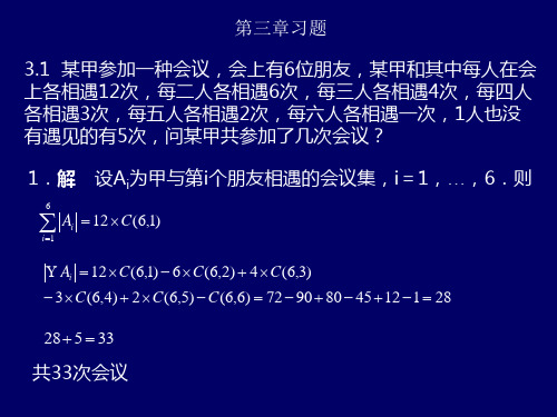
组合数学第三章习题解答
m
i 0 nm
(c )
C (m l 1, m 1) C (m l , m) C (m l , m 1) C (m l , m 2) ...
(1)l C (m l , m l )
(a)
C (n m, n k ) C (n m, k m)
设这66个元素为a1<a2<a3<...<a66
构造b1=a2-a1, b2=a3-a1,…, b65=a66-a1, 令B={b1,b2,…,b65} 这65个元素属于1到326,如果这65个元素有任何一个属于P1, 则定理得证。 否则: B p2 p3 p4 p5 (2)因为。 65 1 1 17 4 因此至少有一个集合含至少B中17个元素,设这个集合为p2。 设这6个元素为: bi1 bi2 ... bi1 7
证明(a)
(a) A B与A B关于B互为余集, 因此 A B B A B
(b) A BC C AC B C A B C A B C与(C B) (C A)互为余集. A B C C (C B) (C A) C C A C B A B C
否则: e1 , e2 p5 构造: e2 e1 同样可证明e2-e1既可表示成p1中数之差,也可表示成p2p3p4中 数之差。 e2-e1是1到326中的数,设f=d2-d1
e p1 p2 p3 p4
因此:1到326的326个整数任意分成5部分,其中必有一部分 其中有一个数是另两个数之差,设ai=aj-ah,那么反过来: aj=ai+ah
3.12,一年级有100名学生参加中文、英文和数学的考试,其中92 人通过中文考试,75人通过英语考试,65人通过数学考试;其中 65人通过中英文考试,54人通过中文和数学考试,45人通过英语 和数学考试,求通过三门学科考试的学生数?
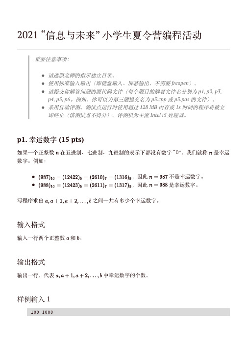
2021江苏省信息与未来小学生夏令营编程活动试题
样例输出 1203样例输⼊ 2900 4096样例输出 2389数据规模对于 40% 的数据,。
对于 100% 的数据,。
p2. 摩尔斯电码 (15 pts)早期的电报机只能表达两种状态:电路导通和电路断开。
电路导通时喇叭可以发声;断开时则不发声。
如何⽤这样的机器来传递⼈类能理解的信号呢?聪明的你⼀定想到了——时间的长短可以表达不同的含义(例如长代表 1、短代表 0),然后再把 “01” 的⼆进制序列对应到字符就可以啦。
摩尔斯电码就是这样⼀种早期的数字通信协议,它通过喇叭发声长短来表⽰不同的英⽂字母:1. 点(半⾓点号.),喇叭响 1 单位时间,读作 “滴” dit;2. 划(半⾓减号-),喇叭响 3 单位时间,读作 “嗒” dah;3. 字符/单词间的停顿,字符停顿 3 单位时间,单词停顿 7 单位时间。
下图列出了摩尔斯电码和英⽂字母之间的对应:例如,⼤家可以试试把 “... --- ...” 对照上⾯的表格翻译成英⽂(空格代表字符的分割)。
没错,这就是著名的 “SOS” 紧急求救信号。
现在,你需要写⼀个程序把收到的摩尔斯电码翻译回英⽂字符。
输⼊格式输⼊数据的第⼀⾏是⼀个整数 ,代表共有 个需要解码的英⽂字母。
输⼊数据的第⼆⾏包含 个摩尔斯电码点/划组成的字符串(字符串之间⽤⼀个空格隔开),每个字符串仅包含若⼲半⾓减号 “-” 和半⾓点号 “.”,且保证能翻译为 26 个英⽂字母中的⼀个。
输出格式输出⼀⾏,为摩尔斯电码解码后得到的字符串。
样例输⼊ 1样例输出 1样例输⼊ 23... --- ...SOS35- .... . --.- ..- .. -.-. -.- -... .-. --- .-- -. ..-. --- -..- .--- ..- -- .--. ... --- ...- . .-. - .... . .-.. .- --.. -.-- -.. --- --.样例输出 2THEQUICKBROWNFOXJUMPSOVERTHELAZYDOG解释:“The quick brown fox jumps over the lazy dog” 是⼀个经典的包含了所有 26 个字母的句⼦。
组合数学及其图论试题库

组合数学及其图论1、一个图G 是指一个有序三元组(V (G ),E (G ),G ϕ),其中G ϕ是:________________.关联函数2、是有40个点的简单图且 中任两个点之间有且只有1条路,则。
393、只有一个顶点所构成的图称为:________________平凡图4、如果H 是G 的子图,其中V (H )=V (G )和E (G )=E (H )至少有一个不成立,就称H 是G 的:_____________.真子图5、设G 是p 阶简单图,则__________________等号成立当且仅当G 是完全图。
q(G)≤p(p-1)/26、如果一条途径的_________与___________相同,就称这条途径为闭途径。
起点 终点7、如果对图G=(V ,E )的任何两个顶点u 与v ,G 中存在一条(u-v )路,则称G 是___________否则称为是______________连通图、 非连通图8、设G 是P 阶连通图,则__________________.q(G)≥p-1 9、若二分图有Hamilton 回路,则与满足 。
10、若G 是2-边连通图,则G 有强连通的________________. 定向图11、边数最少的连通图是 。
树12、没有回路的连通图称为_______________.树13、的图是图或图。
平凡图,不连通图14、树T的每一个非悬挂点都是T的 __________.割点15、二分图中若与满足,则必有完美对集。
16、给定一个图G,如果图G的一个生成子图T是一棵树,则称T是G的一个_______________.生成树17、设G是无环图,e是G的一条边,则τ(G)=___________________________.τ(G-e)+τ(G·e)18、是阶简单图,则,等号成立当且仅当是图。
,完全图 2、19、___________________________的生成树称为最优生成树。
VW_82469_Englisch

Accessory DevicesAcoustic RequirementsPrevious issuesVW 82469: 2005-10, 2006-03ChangesThe following changes have been made as compared to VW 82469: 2006-03:–Evaluation of brief noises expandedScopeThis Standard defines the acoustic requirements and testing conditions that must be fulfilled by the accessory device to be developed, e.g., window lift, control motor, relay, pump, valve.For the time being, the specifications apply to accessory devices that are used in motor vehicles with a conventional combustion engine. For motor vehicles with an electric drive or hybrid vehicles with the combustion engine switched off and the electric drive running, all specifications and limit curves specified below for conventional vehicles with the combustion engine switched off apply.Acoustic evaluation of the accessory device in the laboratory Measuring room The evaluation parameter for the airborne noise is the A-weighted sound level measured according to DIN EN 61672-1, Class 1, or the one-third octave spectrum determined under the same conditions.The measurement must be performed in a free field above a reflective plane. Apart from the reflective plane, all walls of the measuring room must be fitted with sound-absorbing material, such that this does not influence the sound field in the frequency range that is of interest. An example of this is shown in DIN 45635-1 (1984-04, Section 3.5).1 2 2.1 Group Standard VW 82469Issue 2010-03Class. No.:8BG00Descriptors:accessory devices, acoustics, noiseCheck standard for current issue prior to usage.This electronically generated standard is authentic and valid without signature.The English translation is believed to be accurate. In case of discrepancies the German version shall govern.Numerical notation acc. to ISO practice.Page 1 of 15Technical responsibilityStandards Department EGNA/3Dr. Friedrich Bielert Tel.: +49 5361 9 31580EKDV/4 Wolfgang Tiefenbach EKDV Tel.: +49 5361 9 75357Manfred Terlinden Confidential. All rights reserved. No part of this document may be transmitted or reproduced without prior permission of a Standards Department of the Volkswagen Group.Parties to a contract can only obtain this standard via the B2B supplier platform .© Volkswagen Aktiengesellschaft VWNORM-2008-12mThe quiescent noise level in the measuring room must be evaluated using a one-third octave spectrum in the frequency range 20 Hz to 16 000 Hz. The individual one-third octave bands of the quiescent noise level must be at least 10 dB below the corresponding one-third octave levels of the accessory device to be measured.Measuring setupThe measuring setup is based on DIN 45635-1. In accordance with this standard, measurements are performed at different points on a spherical surface at a distance of 1 m from the center of the noise source. The radius vector from the center of the noise source to the spherical surface is the normal of the face surface of the microphone.The number of microphones must first be chosen to be ≥ 9, in accordance with accuracy class 2. The number must be increased as long as the difference in dB between the highest and the lowest mea‐sured total level is numerically greater than the previous number of microphones (in accordance with DIN 45635-1, Section 5.4.4.2). The orientation of the device under test (DUT) with respect to the microphones must be selected in such a way that the maximum sound level is recorded and functional capability of the equipment is assured.If the radiated sound field changes by a sufficiently small amount during the entire period of operation,measurements may be made using fewer than 9 microphones, provided this has been approved by the purchaser.Operation of the accessory deviceOperation of the accessory device for three complete operation cycles (run-in procedure). From the fourth cycle onwards, measuring of every complete operation action (e.g., open, close) of the acces‐sory device five times.Load conditions for the accessory deviceCorresponding to the load conditions that occur during vehicle operation.Measurements under deviating load conditions must be approved by the purchaser.Operating voltage of the accessory deviceOperation of the accessory device at a voltage of 13,5 V, measured at the electrical connectors on the accessory device, except where other operating voltages have been specified.Settings for the measuring systemsThe sound pressure must be recorded over time and represented as A-weighted decibels. The inte‐gration constant (time over which each individual signal level is averaged during the measurement period) must be 125 ms. When a sound level meter is used, this value corresponds to the "fast"setting. The dynamic range must be adjusted to an optimized signal/noise ratio.One-third octave spectrum of the accessory device The maximum A-weighted total sound level that occurs at a spherical surface must be determined according to Section 2.2. If fluctuations occur in the amount of sound emitted over the running time of the accessory device, then the maximum value that occurs temporally and spatially must always be used as the evaluation criterion. The position of the maximum total sound level determined in this manner is used to determine the one-third octave spectrum.2.2 2.3 2.4 2.5 2.6 2.7 Page 2VW 82469: 2010-03A step diagram with the respective one-third octave limit curve is used to represent the A-weighted one-third octave spectrum against the one-third octave center frequencies, in the frequency range 20 Hz to 16 000 Hz (see Figure 1).The one-third octave bands must be determined using the arithmetic average method over the whole running time that is relevant to each application, with use of one-third octave filters in accordance with DIN EN 61260.If significant fluctuations in the one-third octave levels occur during the running time (deviations greater than 3 dB, as compared to the average one-third octave level over the running time), thenthese must be documented separately.The process described must be carried out for at least 3 identical devices. Serial numbers and the point of maximum noise emission must be documented.Figure 1 – One-third octave limit curves for airborne sound from accessory devices during a laboratorymeasurementLegend1Occupant-operated accessory device with combustion engine running 2Occupant-operated accessory device with combustion engine switched off and accessory device starting automatically with combustion engine running 3Accessory device starting automatically with combustion engine switched off Total sound pressure levelThe following total sound pressure level values must not be exceeded:2.8 Page 3VW 82469: 2010-03–65 dB(A)Occupant-operated accessory device with combustion engine running –60 dB(A)Occupant-operated accessory device with combustion engine switched off and accessory device starting automatically with combustion engine running –55 dB(A)Accessory device starting automatically with combustion engine switched offModulation levelTo ensure a high-quality sound impression, the noise emitted by the accessory device must vary only to a limited extent. For adjusting drives, for example, periodic variations of the rotational speed must be avoided (running out of true, "wobbling").Frequency variations over time can be evaluated by plotting the frequency spectrum over time (spec‐trogram) or by plotting the multiples of the rotational speed (orders) over time.The relative frequency change Δf/f of the operating noise must not exceed a value of 1% in one second.Amplitude variations over time can be evaluated, for example, by plotting the sound level over time.The integration constant of the sound level must be selected to be sufficiently small, and must be agreed upon with the purchaser.The relative level change ΔL/L must not exceed a value of 0,5 dB. Changes over time during starting operation or stopping operation (see Figure 2) are excluded from these requirements.Figure 2 shows the starting operation and stopping operation of an accessory device. The course of the operating frequency or the course of the sound level is schematically plotted in any unit as a function of time t.2.9 Page 4VW 82469: 2010-03Figure 2 – Starting and stopping operation of an accessory deviceLegend1Duration of the starting operation 2Duration of the stopping operation 3Mean value 4Instantaneous value TonalityWithin a one-third octave spectrum, an individual one-third octave band must not deviate from both neighboring one-third octave bands by more than 3 dB. A deviation of more than 3 dB from only one of the two neighboring one-third octave bands is permissible.Evaluation of the noise of briefly operating accessory devicesBriefly operating accessory devices are accessory devices for which the sound pressure exceeds 25% of the maximum value for the first time and/or falls below 25% of the maximum value for the last time within a time period T 1 of at most 1 s (Figure 3).The sound pressure used for this criterion must be measured with a minimum sampling rate of 22 kHz.The evaluation described here applies to noises occurring once (e.g., relay clicking) and successions of brief noises (see Figure 4) at a time interval T 2 greater than 0,05 s. For shorter times T 2, the noise is considered to be continuous.2.10 2.11 Page 5VW 82469: 2010-03Figure 3 – Pressure curve over time of a brief noise Figure 4 – Pressure curve over time of a succession of brief noises Section 2.1 through Section 2.5 also apply. The maximum A-weighted sound pressure level occurring in the observed time period applies as the evaluation criterion (time constant "fast", see for example DIN EN 61672-1). The A-weighted sound pressure level of the brief noise according to Figure 3 is given in Figure 5 as an example. The maximum sound pressure level used for the evaluation is marked by an arrow.A one-third octave band evaluation is not performed.Page 6VW 82469: 2010-03Figure 5 – A-weighted sound pressure level of the signal from Figure 3The limits specified in Section 2.8 apply to the maximum level. However, the measured A-weighted sound pressure level receives a pulse increase of 6 dB for the brief noises or successions of brief noises defined above.Subjective evaluationThe noise characteristic of the accessory device must not exhibit any unpleasant noise components,across the entire operating range.The development goal is to ensure that neither the interior nor exterior noise of the accessory device can be perceived as being disturbing. This evaluation represents a prerequisite for release approval.Where necessary, psychoacoustic measurement techniques must be used for objective substantia‐tion.Structure-borne sound from accessory devices Measuring roomThe accessory devices must be evaluated in a low-vibration room.Measuring setupAll connection points that are provided for attaching the accessory device to the vehicle must be fitted with triaxial force sensors. The accessory device must be attached via the force measurement sen‐sors to a rigid support structure (e.g., a solid mounting plate), orientated as it would be when installed (in the vehicle).Operating conditions of the accessory device According to Section 2.3.2.12 33.1 3.2 3.3 Page 7VW 82469: 2010-03Load conditions of the accessory device According to Section 2.4.Operating voltage of the accessory device According to Section 2.5.Determination of one-third octave spectra for forcesThe dynamic forces in the three spatial directions (X, Y, Z) must be recorded for all connection points on the accessory device. These must be interpreted in the form of averaged one-third octave bands,making use of one-third octave filters as described in DIN EN 61260 according to the arithmetic average method.It must be ensured that a sufficiently high sampling rate is used.If significant fluctuations in the one-third octave level occur during the running time (deviations greater than 3 dB, as compared to the average one-third octave level over the running time), then these must be documented separately.The one-third octave spectra for all forces measured at the connection points must be added ac‐cording to the formula:(1)(addition of the rated values).The one-third octave spectrum that results from this equation must be represented as a step diagram below the limit curve, using one-third octave center frequencies in the frequency range 16 Hz to 1000 Hz. The level axis must show a spreading of 40 dB.Limit curves for the one-third octave spectra for forcesThe sum of internal forces that are transmitted at all connection points to the subframe must not exceed the one-third octave limit curve shown below (Figure 6).3.4 3.5 3.6 3.7 Page 8VW 82469: 2010-03Figure 6 – Limit curves for the one-third octave spectra for forcesLegend1Occupant-operated accessory device with combustion engine running 2Occupant-operated accessory device with combustion engine switched off and accessory device starting automatically with combustion engine running 3Accessory device starting automatically with combustion engine switched offFigure 6 shows the limit curves for the total of the forces applied to the connection points by the accessory device in newtons (N) as a function of frequency (Hz).Acoustic evaluation of accessory devices installed in the vehicle Measuring roomExcept for the reflective plane, all walls of the measuring room must be fitted with sound-absorbing material, such that they do not influence the sound field in the frequency range of interest. An example of this is shown in DIN 45635-1, Issue 1984, Section 3.5.The quiescent noise level in the vehicle must be evaluated using a one-third octave spectrum in the frequency range 20 Hz to 16 000 Hz. The individual one-third octave bands of the quiescent noise level must be at least 10 dB below the corresponding one-third octave levels of the accessory device to be measured.All other sources of acoustic interference in the vehicle must be switched off during the measurement.The measurement takes place with the combustion engine switched off.Operation of the accessory deviceOperation of the accessory device for three complete operation cycles (run-in procedure). From the fourth cycle onwards, measuring of every complete operation action (e.g., open, close) of the acces‐sory device five times, using the load conditions specified in Section 4.3 and Section 4.4.44.1 4.2 Page 9VW 82469: 2010-03Load conditions for the accessory deviceCorresponding to the maximum load conditions that occur during vehicle operation.Measurements under deviating load conditions must be approved by the purchaser.Operating voltage of the accessory deviceOperation of the accessory device at a voltage of 13,5 V, measured at the electrical connectors on the accessory device, except where other operating voltages have been specified. If necessary, the vehicle battery must be buffered using an external power supply that can provide sufficient power.The voltage of the power supply must correspond to the voltage of the charge controller with the combustion engine running, i.e., usually ≥ 14,1 V.Interior noise Measuring setup for evaluation of interior noiseThe interior noise must be measured at the positions of the driver's ears and at the positions of the ears of a passenger on the right rear seat. The measurement can be performed with individual mi‐crophones, headband microphones, or an artificial head.Settings for the measuring systems According to Section 2.6.4.3 4.4 4.54.5.1 4.5.2 Page 10VW 82469: 2010-03One-third octave spectrum of the accessory deviceA step diagram with the respective one-third octave limit curve is used to represent the A-weighted one-third octave spectrum against the one-third octave center frequencies, in the frequency range 20 Hz to 16 000 Hz (see Figure 7 and Figure 8). The one-third octave bands must be determined using the arithmetic average method over the whole running time that is relevant to each application,with use of one-third octave filters in accordance with DIN EN 61260.If significant fluctuations in the one-third octave level occur during the running time (deviations greaterthan 3 dB, as compared to the average one-third octave level over the running time), then these must be documented separately.The process described must be carried out for at least 3 devices. The serial numbers must be doc‐umented.Figure 7 – One-third octave limit curves for airborne sound from occupant-operated accessory de‐vicesLegend1With combustion engine running 2With combustion engine switched off4.5.3Figure 8 – One-third octave limit curves for airborne sound from accessory devices starting auto‐maticallyLegend1Start with combustion engine running 2Start with combustion engine switched off Total sound pressure levelThe following total sound pressure level values must not be exceeded:–45 dB(A)Occupant-operated accessory device with combustion engine running –40 dB(A)Occupant-operated accessory device with combustion engine switched off –40 dB(A)Accessory device starting automatically with combustion engine running –35 dB(A)Accessory device starting automatically with combustion engine switched offModulation level According to Section 2.9.Tonality According to Section 2.10.Evaluation of the noise of briefly operating accessory devices According to Section 2.11.Subjective evaluation According to Section 2.12.4.5.4 4.5.5 4.5.6 4.5.7 4.5.8Exterior noise Measuring room The vehicle must be placed in a measuring room according to Section 2.1. A distance between the vehicle body and the walls of at least 2 m must be observed.Measuring setup for evaluation of exterior noiseRecord the exterior noise using a microphone. This microphone must be positioned at the same height as the accessory device, at a distance of 1 m from the vehicle body. The normal of the diaphragm surface of the microphone must be at right angles to the vehicle body.Operation of the accessory device According to Section 2.3.Load conditions for the accessory device According to Section 2.4.Operating voltage of the accessory device According to Section 2.5.Setting of the measuring system Set integration constant and dynamic range according to Section 2.6.One-third octave spectra of the accessory deviceA step diagram with the limit curve is used to represent the A-weighted one-third octave spectrum against the one-third octave center frequencies, in the frequency range 20 Hz to 16 000 Hz (see Figure 9). The one-third octave bands must be determined using the arithmetic average method over the whole running time that is relevant to each application, with use of one-third octave filters in accordance with DIN EN 61260.If significant fluctuations in the one-third octave level occur during the running time (deviations greater than 3 dB, as compared to the average one-third octave level over the running time), then these must be documented separately.The process described must be carried out for at least 3 devices. The serial numbers must be doc‐umented.4.64.6.1 4.6.2 4.6.3 4.6.4 4.6.5 4.6.6 4.6.7Figure 9 – One-third octave limit curves for exterior noise from accessory devicesLegend1With combustion engine running 2With combustion engine switched off Total sound pressure levelThe following total sound pressure level values must not be exceeded:–40 dB(A)With combustion engine running –35 dB(A)With combustion engine switched offModulation level According to Section 2.9.Tonality According to Section 2.10.Evaluation of the noise of briefly operating accessory devices According to Section 2.11.Subjective evaluation According to Section 2.12.4.6.8 4.6.9 4.6.10 4.6.11 4.6.12Referenced documents5The following documents cited in this standard are necessary for application.In this Section terminological inconsistencies may occur as the original titles are used.Standards with the titles given in German are either only available in German or may be procured in other languages from the institution issuing the standard.DIN 45635-1Measurement of noise emitted by machines; airborne noise emission; en‐veloping surface method; basic method, divided into 3 grades of accuracy DIN EN 61260Electroacoustics - Octave-band and fractional-octave-band filtersDIN EN 61672-1Electroacoustics - Sound level meters - Part 1: Specifications。
JEC-37 噪音规范

3 -3
4 -2
5
6
7 -1
8
9
兩差值小於3dB時,此測定沒有可信性。
測試方法
使用符合JIS C 1502要求的噪音計。 2. 使用A加權進行噪音量測。 測試位置:
1. 1.
測試位置為軸中心線在內的水平面,其軸向以及定子外框架的中心位置, 在軸的直角方向上測四個點。麥克風位置如下表: 馬達輸出功率 功率<1KW 功率>1KW 距離(m) 0.5 1
Lw LI1 20log r 11 (半自由空間) Lw LI 2 20log r 8 (自由空間)
又聲音強度水準等於聲音壓力等級
公式合併後為:
Lw Lp 20logr K (半自由空間時,K值為8。自由空間時,K值為11)
JEC-37 噪音規範
LDR3.2013.11.15
測定環境&條件
測試環境: 量測環境需選擇較不易反射噪音的場所。 待測物體最好放置在彈性體上。 最好的測試環境為,測試距離為2倍時,噪音會減少約4dB。 測定條件: 輸入電源需接近正弦波(表示速度迴路增益為最小值)。 測試前需先測量背景噪音(暗噪音)。 合成噪音與背景噪音相差10dB以上時,可以忽略背景噪音的影響。 兩者差值未超過10dB時,需以下表修正合成噪音。
2. 3.
距離是從每個測量點的端部開始計算。 麥克風需放在不受馬達風扇影響的地方。
測定水準
1.
測量儀器需為一般常用的八音度以及1/3八音度頻譜分析儀(Octave band filter),中心頻率為 63、125、250 、500、1000、2000、4000、8000Hz等 八個。 1/3八音度頻帶分析儀則是將八音度頻帶再細分成三份,中心頻率為上截斷頻 率與下截斷頻率乘積的根號值,有24個。 目前士林伺服馬達所使用之B&K頻譜分析儀,為1/3八音度頻譜分析儀。 噪音計的測量值有波動時,應測量多次後,選用其平均值。
音色一览表

Pick Bass
拨片贝司
Fretless Bass
无品贝司
Slap Bass
打弦贝司
Synth Bass
合成贝司
Hi-Q Bass
Hi—Q贝司
Dance Bass
舞曲贝司
STRINGS (弦乐)
String Ensemble
弦乐合奏
Chamber Strings
室内弦乐
Slow Strings
慢弦乐
次中音萨克斯
Alto Sax
中音萨克斯
Soprano Sax
高音萨克斯
Baritone Sax
上低音萨克斯
Breathy Tenor Sax
呼吸萨克斯
Clarinet
单簧管
Oboe
双簧管
English Horn
英国管
Bassoon
巴松管
TRUMPET (小号)
Trumpet
小号
Trombone
长号
Trombone Section
Standard Kit 1
标准打击乐1
Standard Kit 2
标准打击乐2
Room Kit
室内打击乐
Rock Kit
摇滚打击乐
Electronic Kit
电子打击乐
Analog Kit
模拟打击乐
Dance Kit
舞曲打击乐
Jazz Kit
爵士打击乐
Brush Kit
刷击打击乐
Symphony Kit
39 40 41 42 43 44 45 46
47 48 49 50 51 52 53 54 55 56 57 58
59 60