Rhino犀牛教程01—放样Loft
犀牛入门基础教程-让您在短时间内熟悉犀牛软件讲解

我后来又去查看了很多国外著名学院,去他们的course页面看他们在用什么软件。(教育网的唯一好处就是访问edu域名非常快,不管这个学校在北极还是在赤道。)整理出了如下一份表格:(这方面我能确定的信息很少,欢迎补充和更正)。
不同的软件是开发给不同的用途的,用CG标准的建模软件输出模型给制造业肯定是造不出来的。我们先给软件分个类:我们所熟悉的Photoshop、Ai、Coredraw等是属于2D(平面)软件。SKETCHUP、AUTOCAD是属于3D软件。
就3D软件而言,我比较认同的分类是将其分为:CG软件、CAD软件、CAID软件、CAM软件四种:
我选择了进行网络文字犀牛教学,将建模思维融入其中的方式,但最终毕竟还是做成了一个普通无奇的犀牛入门教程。承蒙院学生会学习部的宣传,很多学院的同学加入到了群里,从NCF网站群里也来了很多朋友。从教程的构思到完成前前后后大约付出一个月时间,我最后整理课件的时候发现自己竟然完成了接近四万字和四百多张图片,遂决定成册。
和大家一样接触3D软件也是在大学以后才开始,大二的幼儿园设计课程,某天一位在墨尔本大学留学的同学放假时跑来给我们看了他们在墨尔本大学建筑大学一年级的数字设计课程的成果。当然我也拷了一份:
图1.1A/B:墨尔本大学建筑学院一年级的数字设计课程作品,吴量提供图片。
设计竟然可以这样做,而且个人在审美上也有这样的喜好,但就计算机而言,大一一年我本来已经差不多完全放弃了我在高中的兴趣,现在又被这哥们提起来了,当时问了他这是什么软件做的,他说:“Rhino”,这是我第一次听说犀牛。
犀牛基础教程详细
苹果
三,还是曲线工具 画苹 果蒂, 四。选取圆管工具 《右 击立方体工具 在跳出的实 体工具栏中选取圆管工具 》按提示选取要建立圆管的 曲线。然后在提示窗口输入 起点圆管半径0.1右击,再 输入终点端圆管半径0.4右 击结束。
第4页/共133页
苹果
四。最后按不等距边缘 工具 修整。然后在 提示窗口中输入要导角 的大小0.1。然后选取 要导角的苹果蒂边缘就 成。《右击布尔运算并 集工具 在跳出的实 体工具栏中选倒角工具 。》。 五。文件。保存。完成 。
一:在TOP视图内用 圆形工具 画个圆 ,然后用曲线工具 画如图二所示钥匙前 部分轮廓线《随意像 样就成》。《选定曲 线状态下按F10可调整 。按F11取消调整。》
第19页/共133页
钥匙
二,用修剪工具 修 剪钥匙轮廓线,按提 示先选取剪切用物体 《图上》然后选修要 修剪的物体《图下》 注意:结束操作可以 右击也可以按Enter结 束,不结束可以一直 修剪下去。再按第二 个要删除的物体就是 。
八。按复制工具 再 复制二个立方长条。 注意在right视图内三 根立方条的上下位置 。
第26页/共133页
钥匙
九。按布尔运算差集 工具 《右击布尔 运算并集工具 在 跳 出 的实体工 具 栏 中 选差集工具。》根据 提示选取钥匙实体右 击结束选取,接着再 选取圆柱体和那三个 立方长条,然后右击 结束布尔运算。
第45页/共133页
双轨扫描出的椅子
三。在FRONT视图内 用直径椭圆工具 按 SHIFT键不松作椭圆 ,调整椭圆位置到如 图所示。
第46页/共133页
双轨扫描出的椅子
四。用双轨扫描工具 《右击 曲面工具在 跳出的曲面栏中选双 轨扫描工具》根据窗 口提示先选取二条轨 道。再选择随圆。右 击,再右击。
Rhino犀牛软件_基础教程
ii
目录
编辑 曲 线 与曲 面 ...................................................................................24 组 合.............................................................................................. 24 炸 开 .............................................................................................. 24 修剪与分割 ..................................................................................... 24 控 制 点 编辑 ..................................................................................... 24 曲 线 与曲 面的 阶 数 ............................................................................. 25 变 动 .................................................................................................26 移 动 .............................................................................................. 26 复制.............................................................................................. 26 旋 转.............................................................................................. 26 缩 放 .............................................................................................. 26 镜像 .............................................................................................. 26 定位.............................................................................................. 26 阵 列.............................................................................................. 26 曲 线 与曲 面分析 ...................................................................................27 测 量距离 、角度 及 半 径 ....................................................................... 27 曲 线 与曲 面的 方 向 ............................................................................. 27 曲率.............................................................................................. 27 以 视觉分析 曲 面 ................................................................................ 28 显 示 边缘 ........................................................................................ 29 检 测 .............................................................................................. 30 组 织 模 型 ............................................................................................31 图 层 .............................................................................................. 31 群 组 .............................................................................................. 31 图 块.............................................................................................. 32 分工 作 业 ........................................................................................ 32 批注 .................................................................................................33 尺 寸 标注 ........................................................................................ 33 文字.............................................................................................. 33 标注 引线 ........................................................................................ 34
Rhino全部命令简要说明

Rhino命令列表3Dface绘制三维空间多边形网格面。
3View三视图界面4View四视图界面AddNextU于AddNextV于AddPrevU于AddPrevV于AlignBackground-Bitmap排列对齐背景图的位置。
AllLayereOn打开所有层。
Along沿着一条垂直于一曲线的直线。
Angle测量两线段的角度。
ApplyCrv沿着曲线排列复制物件。
ApplyMesh将一曲面转化成多边形网格。
Arc圆心、半径、夹角绘制圆弧。
Arc3Pt三点绘制圆弧。
ArcDir两点与切线方向绘制圆弧。
ArcTTR依照两曲线之切线绘制圆弧。
Area计算曲面的区域。
AreaCentroid计算曲面的中心。
AreaMoments计算曲面的力矩。
Array排列复制五件。
ArrayCrv沿着曲线排列物件。
ArrayPolar沿着圆形排列复制物件。
ArraySrf沿着曲面排列复制物件。
Arrow绘制一完整标注箭头。
Arrowhead绘制一标注箭头。
Back后视图。
Baseball绘制棒球结构的球体。
BaseballEliipsoid绘制棒球结构的椭球体。
Bend弯曲物体Bisector绘制一条介于两线中间的线段。
Blend将两条曲线顺滑地连接。
BlenzdSrf将两曲面顺滑地连接。
BooleanDifference布尔运算——相减。
BooleanIntersection布尔运算——交集。
BooleanUnion布尔运算——并集。
Bottom下视图。
BoundingBox绘制框住曲线的方形。
Box绘制立方体。
Box3Pt三点建立立方体。
Cap为符合曲面加盖。
Cen捕捉中心点。
Chamfer将两曲线做导角处理。
ChamferSrf将两曲面做导角处理。
ChangeDegree更改曲线的ChangeDegreeSrf更改曲面的ChangeLayer更换物件的图层。
Check检查物件。
Circle画圆:圆心、半径。
犀牛教程

犀牛教程-手机1Rhino教程2010-03-10 23:01:19 阅读511 评论0 字号:大中小订阅Rhino3.0打造精细PDA 作者:王岩——转载自2003年6月《电脑商情报家用电脑》Rhino3.0正式版的推出给rhino爱好者们带来许多的惊喜,虽然它没有向大家预想的那样添加许多新功能,但是更换了系统核心后在执行效率方面得到了很大的改善,至少我们可以使用到更稳定,更快速的犀牛。
这里笔者使用Rhino3.0制作了一个PDA的模型,喜欢Rhino 的朋友可以从中体会Rhino3.0究竟发生了哪些变化,如果你还没有使用过Rhino,那么只要跟着下面的步骤一步步的动手,相信也可以制作出精细的PDA模型。
在制作完这个模型后只要稍加变化就可以制作出类似的手机或电脑的模型。
绘制轮廓:1.要想制作出准确的模型,最好能够找到模型的图片作为参考。
本例中使用了三张背景图片,首先要将参考图片输入到Rhino中并将图片对齐。
运行Rhino3.0后激活顶视图,执行View菜单中的Background Bitmap/ Place命令输入顶视图的参考图片。
先不必考虑图片的尺寸,单击鼠标右键重复输入背景图片命令,分别在侧视图和前视图中输入对应的参考图片。
创建一个长方体作为参照物,使用Background Bitmap/Scale命令调整背景图片的尺寸。
然后执行View菜单中的Background Bitmap/Move命令按照(图1)所示对齐背景图片,(注意轴心的位置)对齐参考图片后将长方体删除。
2.激活顶视图,执行Curve菜单中的Rectangle/Corner to Corner命令,键入“R”后按下回车确定,接着拖出一个矩形,键入“1”后按下回车创建一个圆角矩形。
选中圆角矩形后按下F10键显示出控制点,根据顶视图的参考图片对控制点进行调整,结果如(图2)所示。
3.激活右视图,执行Curve菜单中的Polyline/Polyline命令,根据参考图片创建PDA侧面的大致轮廓。
RHINO介绍性教程(工业系软件培训)

第1课 NURBS建模软件RHINO〔犀牛〕介绍 Rhino和Maya在NURBS建模方面都到达了极高水平。当然它们仍然是各有所长的。Maya结合强大的Artist雕刻工具,更为直观地再现设计人员的构思;而Rhino则以其强大的创建、修改、定位工具到达更高的精细程度。如你表现的是罗丹的浪漫风格的雕塑或者达利般的自由变形,建议你采用Maya;如果你要重现古希腊的写实风格或者后工业时代的精密冷静的产品曲线,那么Rhino是你的首选。 除了与Maya相差无几的建模力量外,Rhino对配置的要求更是显得平易近人,不象Maya、Softimage等贵族般最差也只住windows NT。Rhino可安装于windows95、98当中。最底配置P133上已经可以相当畅快地运行了。做布尔运算的速度让PII上的3dmax也难望其项背。
NURBS曲面概念 Rhino中面、实体、实体部分之间的区别 在Rhino中,面可以由任意的空间曲线围合而成,也可以通过放样、旋转、拉伸形成。这样的面可以通过打开控制点来对其进行编辑修改。Rhino中的实体和实体部分〔partial solids〕可以是单独的封闭曲面〔closed surface〕,也可以是多个曲面组成的〔polysurf〕。实体形成一个封闭的有体积的模型,而实体部分并不闭合,它只是实体的一个部分。在Rhino中,由多个曲面组成的实体和实体部分不能打开控制点进行编辑。你可以将实体炸开〔Explode〕再对各个部件进行修改,但会造成修改后相连接的曲线发生偏移,不能重新组合的情况。因此通常在各部分编辑完成后再将其组合起来。 组合几个面可以用修剪缝合或者布尔运算组合,为了各个部件的完整和可编辑,一般使用缝合工具。 面的创建 1由平面的封闭曲线生成平面(Surface/From Planar Curves) 2由3-4条曲线生成曲面——曲线的线头不一定重合,但要接近,不然生成怪异的曲面了。 3曲线旋转生成曲面 Surface/Revolve——先选中一条曲线,再点2个点确定旋转轴,旋转生成曲面。〔可输入旋转起始终止角度,不一定非360度〕 4曲线扩展成曲面 Extrude (1) 直接扩展Surface/Extrude from Curve/Straight——选定一条曲线,定基点及高度,扩展成曲面。 (2) 选另一条曲线为轴扩展Surface/Extrude from Curve/Alone a Curve——先选曲线,再选轴。 (3) 曲线向一点收缩成曲面Surface/Extrude from Curve/To a point——先选曲线,再选任一点位置。 5曲线Sweep成曲面 Surface/Sweep Alone Path——顺序选曲线,按空格键或回车结束;选一条路径曲线,再按空格键或回车。〔做窗帘最合适〕 6曲线Rule成曲面〔多条曲线顺续连成曲面〕选Surface/Rule——顺序点曲线,最后按空格或回车。 7曲线loft成曲面〔多条曲线顺续连成曲面〕选Surface/loft——顺序点曲线,最后按空格或回车,与Rule不同的是:loft加上了平滑处理。 8曲线双规Sweep成曲面——顺序选曲线,按空格键或回车结束;选2条路径曲线,再按空格键或回车。〔好象曲线与轨道要先接好,否则后果难料〕。曲线与轨道的连接:先选中曲线〔变黄〕,点屏幕下部的Osnap,选End;菜单Transform/Align;选曲线的2端点,再选轨道的2个端点,曲线经过缩放。放到轨道端点上。〔取消Osnap选择〕 9曲面的切割成形〔很重要的功能,许多NURBS软件无此功能〕——做好一个曲面A,用曲线、曲面及物体当切割工具,移到想切割曲面A的部位。选菜单Edit/Split,先点曲面A,再顺序点其他的切割工具。回车。 10两个曲面Blend连接 选Surface/Blend——选想连接的曲面的边,回车。〔Blend产生了另一个曲面,可用Edit/join连成一体,但连后就不能改了!!!这是Rhino的缺点〕
最新版犀牛入门教程建筑方向

最新版犀牛入门教程建筑方向NCF寒假Rhino入门教程系列by王大川/doc/746496823.html,/forumdisplay.php?f id=66&filter=type&typeid=20寒假RHINO入门教程系列 (5)第一课LESSON1 概述 (5)第二课LESSON2 (11)2.1R HINO界面 (11)2.1.1界面构成 (11)2.1.2如何使用工具面板 (13)2.1.3自定义工具集 (14)2.2R HINO视窗 (16)2.2.1视窗基本操作 (16)2.2.2在底部显示视图标签 (17)2.2.3视窗显示模式 (18)第三课LESSON3 绘制2D物体 (20)3.1R HINO中的对象介绍. (20)3.1.1点物体 (20)3.1.2线物体 (20)3.1.3面物体 (21)3.1.4网格 (22)3.2点物体的绘制 (23)3.3曲线绘制 (25)3.3.1 Rhino直线绘制 (25)3.3.2 Rhino曲线绘制 (28)3.3.3其他封闭几何形体 (31)作业 (33)第四课LESSON4 绘制2D物体(下) (34) 4.1曲线编辑 (34)4.1.1曲线的分割和修剪 (34)4.1.2编辑曲线上的点 (37)4.1.3曲线编辑工具 (39)4.2对NURBS曲线的深入理解 (42)第五课LESSON5 曲面命令(上) (55)5.1构建曲面 (55)5.1.1创建方形平面 (56)5.1.2绘制简单曲面 (57)5.1.3拉伸曲面 (60)5.1.4放样(LOFT) (63)5.1.5扫琼 (67)5.1.6旋转命令 (69)5.1.7边界曲面、闭合线曲面、镶面的区别 (70) 第六课LESSON6 曲面命令(下) (74)6.1点的编辑 (74)6.2分割和修剪 (80)6.2.1 曲线作为分割边界 (80)6.2.2 曲面作为分割边界 (82)6.2.3 还原分割和修剪 (83)6.3链接曲面 (84)6.4延伸曲面 (84)6.5曲面倒角 (85)6.6偏移工具 (86)6.7混接曲面 (88)6.8合并曲面 (90)6.9衔接曲面 (91)第七课LESSON7 (96)7.1基本几何体创建 (96)7.2实体工具 (100)7.2.1 布尔运算 (101)7.2.2 抽面工具 (103)7.2.3 实体倒角 (104)7.3 MESH对象 (106)第八课LESSON8 (109)8.1从物件建立曲线 (109)8.1.1 曲线投影到曲面 (109)8.1.2从曲面提取边界线 (111)8.1.3从曲面提取轮廓线 (111)8.1.4从曲面提取UV线 (111)8.1.5 生成相交线 (112)8.1.6 生成等分线 (112)8.1.7 生成剖面线 (113)8.2物件变动工具(上) (113)8.2.1 处理物件空间位置的工具 (114)第九课LESSON9 (122)9.1变动工具(下) (122)9.1.1 特殊位置工具 (122)9.1.2 特殊变形工具 (131)9.2NURBS曲面理解 (135)第十课LESSON 10 RHINO辅助工具 (139) 10.1图层控制 (139)10.2物件属性 (140)10.32D工具 (143)10.3.1 标注工具 (143)10.3.2 Make 2D (144)10.3.3 ArchCut工具 (147)第十一课LESSON11渲染 (150)10.1渲染相关知识 (150)10.1.1 渲染分类 (150)10.1.2 渲染特性 (150)10.1.3 我们需要的静帧渲染 (157)10.2R HINO 中的渲染 (158)10.2.1 渲染前的准备 (158)10.3R HINO 中的几种渲染器介绍 (162)附表一:犀牛中的插件介绍 (167)附表二:本次网络课程的课程表 (168)寒假Rhino入门教程系列第一课LESSON1 概述这是本次犀牛课程的第一节课,但本课不会涉及任何关于犀牛建模的知识,而且图片较少文字较多。
犀牛 rhino超详细实例教程
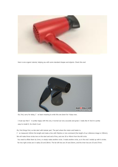
Here is one organic tutorial, helping you with some standard shapes and objects. Check this one!Ok, first, sorry for delay, I’ve been meaning to write this one down for 4 days now.I must say that I’m pretty happy with this one, it turned out very accurate and great. I really like it! And it is prettyeasy to model it. So check it out:Ok, first things first, so lets start with tubular part. The part where the motor and heater is.I’ve measured 120mm the length and make a line with Polyline or Line command (the length of our reference image is 190mm). We will make three circles two on the start and end of line, and one 30 or 40mm from the left circle.You need to offset them by 2mm, or simply make another circle. I made another circle, so in the end I ended up with 6 circles. Far two right circles are in radius 26 and 28mm. The far left two are 34 and 36mm, and the inner two are 35 and 37mm.Using InterpCrv command make a line connecting three outer circles. (use Quad option in Osnap for easier snapping). Next, do the same step for 3 inner circles.Using Sweep2 for first and second rail select outer two circles, and for cross section curve select Curve we made earlier. Make an ellipse and position it like on the image below:Next, from Front viewport use Project command to project that ellipse onto our tubular surface. You will get two curves on the surface, and we need only the front one. Using it, we will trim the surface and make a hole:Now, we’ll move onto handle. I like jumping from one part to another, I guess you already found that outFrom top viewport using reference image, outline outer edges with InterpCrv. Just to make sure, I made a straight horizontal linein Top viewport (using Ortho) and trimmed off the two curves. Now, we are sure those two curves has endings in the same cplane.Create another ellipse, this time one radius 15mm and other 13mm. Using End and Quad options in Osnap, position the ellipsebetween two curves, first move it to the end of one curve, and using PointsOn command, stretch the ellipse to fit the other curve’s end.Copy that ellipse, and position it like on the image below. You also need to stretch it with moving control points so it touches both curves.I have also made this ellipse 4 points higher. So, select upper three control points and move them 4 units up,and then move lower three control points and move them by 4 units (mm) down.Next, using that second bigger ellipsoid and two handle curves, we will make a sweep2.Using DupBorder we will duplicate border of newly created surface. We will get two closed curves, and we need the little one only, as we already have the bigger one. So, now, delete the surface, and again create sweep2 rail between two rail curves,and using now three closed curves:And now, we have a handle! Next, we will blend the two surfaces, so use BlendSrf command. Note that we need to check the Same height shapes option:Hopefully you got something like on the image below:Now, lets cap the tubular part.From the end of the first Line we created in this tutorial, create another line, and make it 10units (mm) long.Now, using Quad option in Osnap create InterpCrv (Curve: Interpolated Points) between two Quad points as start and end, and in the middle top of the 10mm long line:Trim one half of the newly created curve (arch) with 10mm long line, and that half arch needs to be revolved.I used Sweep1 and followed outer circle. But before that, we need to offset that half arch,and we need to move the inner circle by 2mm right from Top viewport(2mm will be the thickness of our shell - yeah, we still need to do that manually ).Now, we can use Sweep1 and make two surfaces:Ok, now, we will make little holes on the rear. From Right viewport make an ellipse 5×2.5mm. Rotate it for 45 degrees, and position like on the image:Using ArrayPolar make an array of 24 holes. Naturally the center would be the same center of circular surfaces.Next, using Copy and Paste duplicate those 24 ellipses, and using Scale shrink them,so you have 5 rows of 24 ellipses each row smaller than the previous.I have grouped each row of ellipses, and will extrude them one group at the time so I have more control, and less mess. So, extrude the ellipses and trim with two circular surfaces:Now, we will make just the same handle and tubular surface, but 2mm smaller.Using all those smaller circles, and smaller curves, we will make inner side of our dryer.You could use offset, but when using it curves are often made out of too much control points,and therefore your surfaces end up with much more isoparms, and we want our models cleaner.You could use Rebuild to make curves better, but then you might loose the original position of your curves. It is a bit tricky, and recreating all the curves, but 2mm smaller is a lot better way.Now, we need to blend the inner and outer surface where the air blows out.Next, on the part where the air is sucked in, using FilletEdge and 2mm as radius round that edge:Lets get back to our first 120mm long line. On the other end (the end there the air blows out from the dryer) create another circle with radius of 6.5mm. The second one from the same center but with 8mm as radius, and another one with radius of 10mm, then one with 16, and one with 18mm radius.Extrude those 5 circles by -15mm (minus is because we need it to go left when looking at it from Top viewport). Do not use Cap option.Next, you will blendsrf paired circles.The one in the middle, the smallest circle, using Arc command we will make an arc like on the image below:Using sweep1 command make a cap:Using Line or Polyline mimic the image below. I first created one line through the center,and then copied it and rotated by 90 degrees, next, I copied those two and rotated by 45 degrees. Next, each line I offset by 1mm up and down, and deleted the middle line.I have also offset the outer circle by 2mm, and aligned everything in the same cplane.And for the end of this part we will extrude those curves by 5mm with Cap option set to yesNow, lets make a little hole in the handle. For hanging the dryer on the wall or something. Create a closed curve like on the image below and trim what is inside:We will make three cross section curves, actually two lines, and one curve and using Sweep2 make a surface: (don’t forget to use Closed sweep option)Join that surface with handle surface, and fillet the two edges with 0.5mm radius:Next, lets create a curve for splitting the handle:Offset that curve by 0.3mm, and trim off what is between two curves:Now we need to blend the inner and outer shell surface (for both sides same settings):hair_dryer_41.jpg(67 KB, 下载次数: 21)STEP 4In this step we will be dealing with dryer cap that concentrates the hot air direction. We will use outer circle of right side of our tubular part:This circle needs to be offset by 4mm to the inside. From the center of this circle start a line 35mm long:Again, using InterpCrv make a curve starting from one Quad point on outer circle,middle of it is in the end of line, and the end of this curve is in the opposite Quad point.From the end and start make two lines. Having Ortho set to on helps!hair_dryer_45.jpg(22 KB, 下载次数: 16)Now, using Match, match the curve to both lines, and set the Continuity and Preserve other end to Tangency. hair_dryer_46.jpg(46 KB, 下载次数: 20)(Note: if you want to match the one end of a curve to the line, then you need to first click near the one end on the curve, then on the line) Using the line that is in the center (you might need to move it to the right a little - just so it crosses your curve (arch)) trim the curve.Use Sweep1 to rail revolve and make a cap.hair_dryer_48.jpg(21 KB, 下载次数: 13)Next, make an ellipse. First end of axis is at 77m, and second at 22mm.(select Diameter from command options selection). And then make another ellipse,again use Diameter, and set 48×14mm. Position both centres of these two ellipses in the same point.hair_dryer_49.jpg(36 KB, 下载次数: 15)I have positioned the both centres of two ellipses to the center of our cap, and then I moved it to the right a little:Now, move the inner ellipse for 42mm to the inside:hair_dryer_51.jpg(27 KB, 下载次数: 14)Using InterpCrv, create a curve between two coplanar Quad points on two ellipses. Now it seems like it is a line,but if you turn on the control points you will get two more cpoints in side this so called line, select two and move outside a little:Using Sweep2 use two ellipses as rail curves, and one connecting curve as cross section. hair_dryer_53.jpg(30 KB, 下载次数: 18)Trim the parts we don’t need:Now, we will make a fillet between these two surfaces… First I joined these two as I wanted to make a FilletEdge, but that didn’t turn out good, so I Exploded the mesh, and made a FilletSrf between these two surfaces.The radius was 10mm and everything went well. If you encounter problems with both FilletEdge and FilletSrf,try reducing od increasing the radius, and if that doesn’t work either, then try the pipe method.hair_dryer_55.jpg(28 KB, 下载次数: 15)Now, using the same exact method we did before for shelling, we will make a shell for this dryer part.Then, we will make one big circle from the center of our little part:hair_dryer_56.jpg(63 KB, 下载次数: 20)Still in the top viewport, we will Trim off the cap, so we get that round edge and BlendSrf the edges(you can either try JoinEdge command to join broken edges, or you can blend 4 time, and then join everything):Now, on the back of this part, make a cross section curve like on the image below: Use polyline hair_dryer_58.jpg(38 KB, 下载次数: 19)And using Sweep2, make a surface:Then, you can fillet the edges.hair_dryer_60.jpg(74 KB, 下载次数: 15)STEP 5Start with ellipse in Right viewport. (Click on diameter option) and input for end of first axis 32mm, and for end of second axis 16mm.Now, using Rectangle (select Rounded option) make a rectangle (first length 20mm, and second 13mm, and center it in the center of our ellipse: hair_dryer_62.jpg(42 KB, 下载次数: 16)Rotate the two curves from top viewport, and extrude with no other extrusion options: hair_dryer_63.jpg(87 KB, 下载次数: 17)Trim the inner part of outer shell of our dryer with extruded ellipse, and split the inner shell of dryer with extruded rounded rectangle:Loft the edges:hair_dryer_65.jpg(34 KB, 下载次数: 16)Fillet the Edge with 1mm radius.Now, create this little rounded rectangle, and position it like on the image:hair_dryer_67.jpg(21 KB, 下载次数: 15)Project it on the blue surface, and extrude that projected curve by 3mm (-3mm) and make a cap with Patch command. hair_dryer_68.jpg(26 KB, 下载次数: 16)STEP 6And for the end, we will make another button. The first one was for controlling the fan speed, and this one is On/Off button. So, create an Ellipsoidhair_dryer_69.jpg(73 KB, 下载次数: 19)Offset that ellipsoid with OffsetSrf command by 0.5mm towards outside. With the bigger ellipsoid trim the handle:Fillet the edges with 0.4mm, and you’re donehair_dryer_71.jpg(89 KB, 下载次数: 19)。